Embed Size (px)
Citation preview
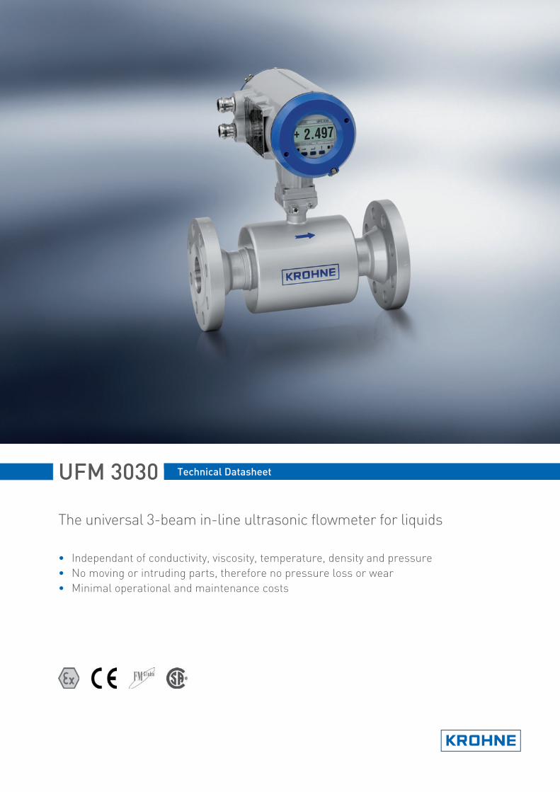
UFM 3030 Technical Datasheet
The universal 3-beam in-line ultrasonic flowmeter for liquids
• Independant of conductivity, viscosity, temperature, density and pressure
• No moving or intruding parts, therefore no pressure loss or wear
• Minimal operational and maintenance costs
UFM 3030 nnnnnnnnnnnnnnnnnnnnnnnnnnnnnnnnnnnnnnnnnnnnnnnn
www.krohne.com 2
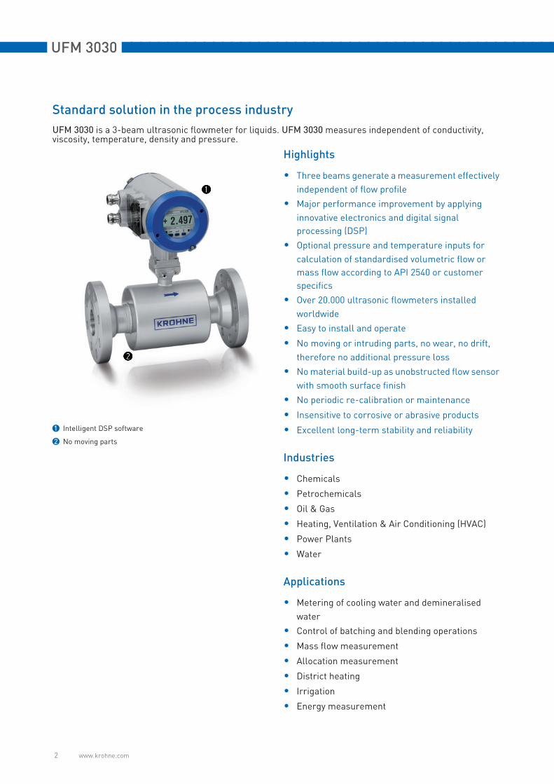
Standard solution in the process industry
UFM 3030 is a 3-beam ultrasonic flowmeter for liquids. UFM 3030 measures independent of conductivity, viscosity, temperature, density and pressure.
1 Intelligent DSP software
2 No moving parts
Highlights
• Three beams generate a measurement effectively
independent of flow profile
• Major performance improvement by applying
innovative electronics and digital signal
processing (DSP)
• Optional pressure and temperature inputs for
calculation of standardised volumetric flow or
mass flow according to API 2540 or customer
specifics
• Over 20.000 ultrasonic flowmeters installed
worldwide
• Easy to install and operate
• No moving or intruding parts, no wear, no drift,
therefore no additional pressure loss
• No material build-up as unobstructed flow sensor
with smooth surface finish
• No periodic re-calibration or maintenance
• Insensitive to corrosive or abrasive products
• Excellent long-term stability and reliability
Industries
• Chemicals
• Petrochemicals
• Oil & Gas
• Heating, Ventilation & Air Conditioning (HVAC)
• Power Plants
• Water
Applications
• Metering of cooling water and demineralised
water
• Control of batching and blending operations
• Mass flow measurement
• Allocation measurement
• District heating
• Irrigation
• Energy measurement

nnnnnnnnnnnnnnnnnnnnnnnnnnnnnnnnnnnnnnnnnnnnnnnn UFM 3030
www.krohne.com 3
In-line Ultrasonic process flowmeter family
The UFM 3030 liquid process flowmeter consists of a UFS 3000 flow sensor and a flow converter, UFC 030. A
UFS 3000 flow sensor can be build together with a UFC 030 flow converter as a compact flowmeter or can be
installed separate as a field version.
UFC 030 flow converter
1 The flowconverter is fully digital and fitted with a digital signal processor and advanced software for optimal performance
2 For in-depth analysis of application and evaluation of flowmeter performance, the soundcheck interface and software is available
Ultrasonic liquid flow sensor family
1 The UFS 3000, the universal ultrasonic flowsensor for liquids
2 For extreme high or low temperature applications from -170 up to 500 deg. C, the UFS 500 HT/LT flowsensor is available
3 For open channels or onsite welding in of sensors the UFS 800 C (for open channels) or OPTISONIC 800 W (weld in) are available. De-
pending on the pipe size the UFS 800 W can be fitted with 1, 2 or even 3 sensor pairs for optimal measurement performance
4 For piping that can not be drained, the UFM 800 HT (hot tap) is available. The UFM 800 HT can be fitted in 1, 2 or 3 path configuration
depending on the pipe size, while the pipe remains filled and pressurized
The OPTISONIC 7060 C is a process gasflowmeter with a wide application range that can be used under harsh
conditions.
The OPTISONIC 7060 C consists of a flow sensor, OPTISONIC 7000 and a flow converter UFC 060. Standard the
OPTISONIC 7000 is build together with a UFC 060 as a compact flowmeter
OPTISONIC 7060 C process gas flowmeter
1 The OPTISONIC 7060 C: a robust flow sensor combined with the UFC 060 flow converter, with a digital signal processor for optimal
performance
2 The converter provides a range of diagnostics parameters. A software package is available for configuration, visualisation and analysis
of diagnostics information
UFM 3030 nnnnnnnnnnnnnnnnnnnnnnnnnnnnnnnnnnnnnnnnnnnnnnnn
www.krohne.com 4
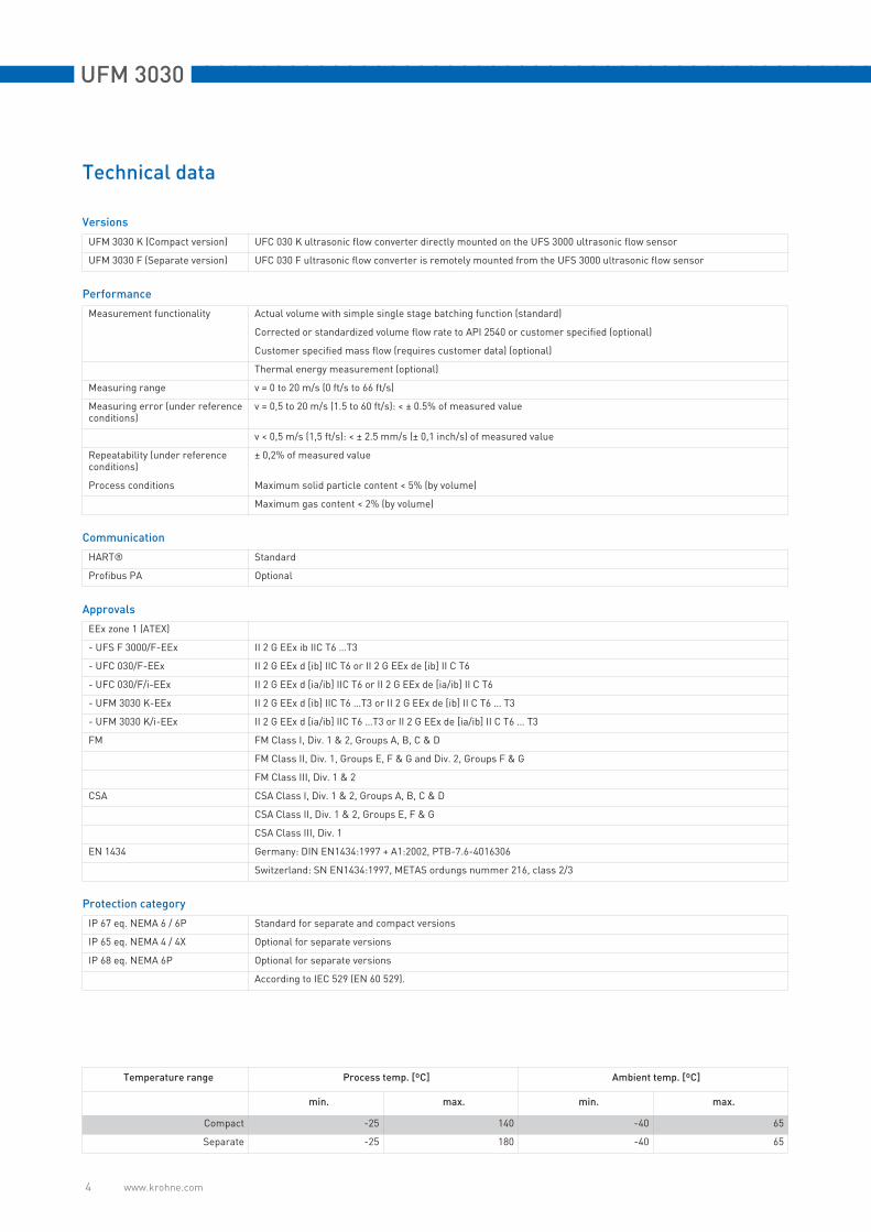
Technical data
Versions
UFM 3030 K (Compact version) UFC 030 K ultrasonic flow converter directly mounted on the UFS 3000 ultrasonic flow sensor
UFM 3030 F (Separate version) UFC 030 F ultrasonic flow converter is remotely mounted from the UFS 3000 ultrasonic flow sensor
Performance
Measurement functionality Actual volume with simple single stage batching function (standard)
Corrected or standardized volume flow rate to API 2540 or customer specified (optional)
Customer specified mass flow (requires customer data) (optional)
Thermal energy measurement (optional)
Measuring range v = 0 to 20 m/s (0 ft/s to 66 ft/s)
Measuring error (under reference conditions)
v = 0,5 to 20 m/s (1.5 to 60 ft/s): < ± 0.5% of measured value
v < 0,5 m/s (1,5 ft/s): < ± 2.5 mm/s (± 0,1 inch/s) of measured value
Repeatability (under reference conditions)
± 0,2% of measured value
Process conditions Maximum solid particle content < 5% (by volume)
Maximum gas content < 2% (by volume)
Communication
HART® Standard
Profibus PA Optional
Approvals
EEx zone 1 (ATEX)
- UFS F 3000/F-EEx II 2 G EEx ib IIC T6 …T3
- UFC 030/F-EEx II 2 G EEx d [ib] IIC T6 or II 2 G EEx de [ib] II C T6
- UFC 030/F/i-EEx II 2 G EEx d [ia/ib] IIC T6 or II 2 G EEx de [ia/ib] II C T6
- UFM 3030 K-EEx II 2 G EEx d [ib] IIC T6 …T3 or II 2 G EEx de [ib] II C T6 … T3
- UFM 3030 K/i-EEx II 2 G EEx d [ia/ib] IIC T6 …T3 or II 2 G EEx de [ia/ib] II C T6 … T3
FM FM Class I, Div. 1 & 2, Groups A, B, C & D
FM Class II, Div. 1, Groups E, F & G and Div. 2, Groups F & G
FM Class III, Div. 1 & 2
CSA CSA Class I, Div. 1 & 2, Groups A, B, C & D
CSA Class II, Div. 1 & 2, Groups E, F & G
CSA Class III, Div. 1
EN 1434 Germany: DIN EN1434:1997 + A1:2002, PTB-7.6-4016306
Switzerland: SN EN1434:1997, METAS ordungs nummer 216, class 2/3
Protection category
IP 67 eq. NEMA 6 / 6P Standard for separate and compact versions
IP 65 eq. NEMA 4 / 4X Optional for separate versions
IP 68 eq. NEMA 6P Optional for separate versions
According to IEC 529 (EN 60 529).
Temperature range Process temp. [ºC] Ambient temp. [ºC]
min. max. min. max.
Compact -25 140 -40 65
Separate -25 180 -40 65
nnnnnnnnnnnnnnnnnnnnnnnnnnnnnnnnnnnnnnnnnnnnnnnn UFM 3030
www.krohne.com 5
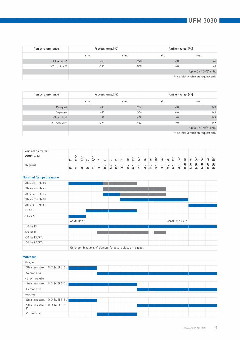
XT version* -25 220 -40 65
HT version ** -170 500 -40 65
* Up to DN 150/6" only.
** special version on request only
Temperature range Process temp. [ºF] Ambient temp. [ºF]
min. max. min. max.
Compact -13 284 -40 149
Separate -13 356 -40 149
XT version* -13 428 -40 149
HT version** -274 932 -40 149
* Up to DN 150/6" only.
** Special version on request only
Nominal diameter
ASME [inch]
1"
11/4"
1,5"
2"
2,5"
3"
4"
5"
6"
8"
10"
12"
14"
16"
18"
20"
24"
28"
32"
36"
40"
48"
56"
64"
72"
80"
DN [mm]
25
32
40
50
65
80
100
125
150
200
250
300
350
400
450
500
600
700
800
900
1000
1200
1400
1600
1800
2000
Nominal flange pressure
DIN 2635 - PN 40
DIN 2634 - PN 25
DIN 2633 - PN 16
DIN 2632 - PN 10
DIN 2631 - PN 6
JIS 10 K
JIS 20 K
ASME B16.5 ASME B16.47, A
150 lbs RF
300 lbs RF -
600 lbs RF/RTJ
900 lbs RF/RTJ
Other combinations of diameter/pressure class on request.
Materials
Flanges
- Stainless steel 1.4404 (AISI 316 L)
- Carbon steel
Measuring tube
- Stainless steel 1.4404 (AISI 316 L)
- Carbon steel
Housing
- Stainless steel 1.4404 (AISI 316 L)
- Stainless steel 1.4404 (AISI 316 L)*
- Carbon steel
Temperature range Process temp. [ºC] Ambient temp. [ºC]
min. max. min. max.

UFM 3030 nnnnnnnnnnnnnnnnnnnnnnnnnnnnnnnnnnnnnnnnnnnnnnnn
www.krohne.com 6
Connection box
- Aluminum, polyurethane coated
- Stainless steel
Transducer window
- Stainless steel 1.4408 (AISI 316 L)
* Individual external transducer housing.
Finish
Standard paint, silver
Offshore paint system, silver
Other paint systems on request.
Calibration
On 2 points, with water
According to RvA
Protection category
IP 67 eq. NEMA 6
IP 68 eq. NEMA 6P (UFS 3000 F)
According to IEC 529.
Sensor cable
Connection
- M20 x 1,5
- 1/2" NPT
- PF 1/2
Cable length
- 5 m / 15 ft
- 10 m / 30 ft
- 15 m / 45 ft
- 20 m / 60 ft
- 25 m / 75 ft
- 30 m / 90 ft
For separate versions only.
J standard J optional U on request
Nominal diameter
ASME [inch]
1"
11/4"
1,5"
2"
2,5"
3"
4"
5"
6"
8"
10"
12"
14"
16"
18"
20"
24"
28"
32"
36"
40"
48"
56"
64"
72"
80"
DN [mm]
25
32
40
50
65
80
100
125
150
200
250
300
350
400
450
500
600
700
800
900
1000
1200
1400
1600
1800
2000

nnnnnnnnnnnnnnnnnnnnnnnnnnnnnnnnnnnnnnnnnnnnnnnn UFM 3030
www.krohne.com 7
UFC 030 converter
General The converter has a backlit local display with three push buttons. All operation can be done by push button or using a hand-held bar magnet, without opening the converter housing.
Applied materials
Converter housing
- Die-cast aluminum Standard
- Stainless steel 316 L (1.4404) Option
Finish
Standard paint, silver Standard
Offshore paint system, silver Option
Other paints on request
Protection category
IP 67 eq. NEMA 6 Standard
to IEC 529
Functionality
Continuous measurement of actual volume flow rate and actual volume total
Standard
HART® communication Standard
Flow direction (forward or reverse) Standard
Velocity of Sound (VOS) Standard
Signal strength Standard
Self diagnostics Standard
Simple single stage batching Standard
Corrected or standardized volume flow rate to API 2540 or customer specified
Option
Customer specified mass flow (requires customer data)
Option
Profibus PA Option
Thermal energy measurement Option
Local display
Operation With cover removed, all display operations incl. changing settings and parameters can be done using the push buttons. With cover in place the measured values and (error) messages can be viewed. Error resetting is still possible; in this case only with the help of an hand-held bar magnet.
3-field LCD The converter has a backlit local display with 3 push buttons. 1st line 8 character 7 segment alphanumeric display and symbols for key acknowledgement 2nd line 10 character, 14 segment text display 3rd line 5 markers to identify display in measuring mode
Parameters Standard Actual volume flow rate in m3, barrels, liters, US gallons or user defined volume unit per hour, minute, second, or user defined time unit
Standard Actual volume total in m3, barrels, liters, US gallons or user defined volume unit (positive, negative, and sum totals), minimum 1 year overflow time
Option Velocity of sound in m/s or ft/s
Option Errors (flashing display and error code)
Option Signal strength (in dB)
Standard Corrected standard volume flow rate in m3, barrels, liters, US Gallons or user defined volume unit per hour, minute, second or user-defined time unit
Option Calculated mass flow rate in user defined mass unit

UFM 3030 nnnnnnnnnnnnnnnnnnnnnnnnnnnnnnnnnnnnnnnnnnnnnnnn
www.krohne.com 8
Option Corrected standard volume total in m3, barrels, liters, US Gallons or user defined corrected volume unit, minimum 1 year overflow time
Option Calculated mass total in user defined unit, minimum 1 year overflow time
Option Analog input in °C, °F, bar or psig
Option Thermal power
Option Thermal energy totalized
Languages
- English Standard
- German Standard
- French Standard
Galvanic isolation
Standard All inputs and outputs are galvanically isolated from the power supply, but not from each other
Optional Namur NE 43, pulse/status outputs and analog 4-20 mA output fully galvanicallty separated
Time-constant
0.025...99 seconds (programmable in increments of 0.01; 0.1 and 1.0 seconds)
Low-flow cut-off
cut-off active value 1...19%, programmable in increments of 1%
cut-off deactive value 2...20%
Power supply
Mains supply 100…240 V AC (48...63 Hz) +10% / -15%
Standard
Low voltage supply 24 V (AC or DC), AC: -10% / +15%, DC: 18...35 V
Option
Power consumption 10 VA / 10 W
Cable connection
M20 x 1,5 Standard
1/2" NPT Option
PF 1/2 Option
(for power supply and signal cables)
Current output
Function Standard Continuous measurement of actual volume flow rate
Standard Flow direction indication (forward or reverse)
Standard Velocity of Sound (VOS)
Standard Transducer signal gain (dB)
Option Corrected or standardized volume flow rate to API 2540 or customer specified
Option Corrected or standardized volume flow rate to API 2540 or customer specified
Settings for Q = 0% 0...16 mA programmable in increments of 1 mA (Limit 20...22 mA)
for Q=100% 4...20 mA
Connection Active mode using internal power supply 24 V DC, load ≤ 680 Ohm
Passive mode external voltage 18 ... 24 V DC, load ≤ 680 Ohm
Pulse output
Function Pulse output
Pulse per volumetric unit (m3, barrels, liters, US gallons or user defined volume unit per hour, minute, second or user defined time unit)

nnnnnnnnnnnnnnnnnnnnnnnnnnnnnnnnnnnnnnnnnnnnnnnn UFM 3030
www.krohne.com 9
Standard Actual volume
Option Corrected or standardized volume to API 2540 or customer specified
Option Customer specified mass (requires customer specific density input)
Option Thermal energy measurement
Frequency output
Pulse rate
Standard Continuous measurement of actual volume flow rate
Standard Velocity Of Sound (VOS)
Standard Transducer signal gain (dB)
Standard Pressure or temperature indication based on analog input (1) or (2)
Option Corrected or standardized volume flow rate to API 2540 or customer specified
Option Customer specified mass flow (requires customer specific density input)
Status output
Standard Diagnostics alarm path errors, totalizer overrun, all errors, analog input
Standard Flow direction indication (forward or reverse)
Standard Batch volume reached
Standard Alarm trip point (high and low) based on actual volume flow rate
Settings Pulse output Pulse/unit (max. 2000 Hz) (example 1000 pulses/barrel) pulse duty cycle 25, 50, 100, 200, or 500 ms for frequency < 10 Hz
Frequency output 0...2000 Hz (example Q0% - 0 Hz, Q100% - 1000 Hz) at 100% of scale value, max. frequency = 2 kHz
Status output On or Off
Connection Pulse, frequency and status output
Active Connection to electronic counters using internal power supply 24 V DC / I ≤ 50 mA
Passive Connection to electronic (EC) or electromechanical counters (EMC) external voltage 19...32 VDC / I ≤ 150 mA
Analog input
Function Option Corrected volume version: inputs to connect temperature and pressure signals for the corrected standard volume, acc. to API 2540, user defined volume or mass flow
Setting Standard Input A1 For volume correction, unit °Celsius or °Fahrenheit
Temperature for 4...20 mA, max. temperature range -50...150°C (-58...302°F)
Option Input A2 For volume correction (pressure), unit bar or psi
Pressure for 4...20 mA, max. pressure range 100 Bar (1450 psi)
Connection Input A1 4…20 mA for temperature sensor
Active (using UFC 030 24 V DC power) or passive, Load 58 Ohm
Input A2 4...20 mA for pressure
Active (using UFC 030 24 V DC power) or passive, Load 58 Ohm
Option Thermal energy measurement: inputs to connect two temperature sensors for measurement of temperature difference to calculate thermal energy
Setting Standard Input A1 For heat measurement (temperature), unit °C or °F
Temperature for 4...20 mA, max. temperature range -50...150°C (-58...302°F)
Standard Input A2 For heat measurement (temperature), unit °C or °F
Temperature for 4...20 mA, max. temperature range -50...150°C (-58...302°F)
Connection Input A1 4...20 mA for temperature sensor
Active (using UFC 030 24 V DC power) or passive, Load 58 Ohm
UFM 3030 nnnnnnnnnnnnnnnnnnnnnnnnnnnnnnnnnnnnnnnnnnnnnnnn
www.krohne.com 10
Input A2 4...20 mA for temperature
Active (using UFC 030 24 V DC power) or passive, Load 58 Ohm
Control input
Function Option Reset totalizer
Option Acknowledge errors
Option Force outputs to zero
Option Initiate batch (see operating instructions for description of this function)
Setting On or Off
Connection Input voltage (Uin) Low: Uin < 5 V (off)
High: Uin > 15 V (on)
Max.: Uin = 32 V
nnnnnnnnnnnnnnnnnnnnnnnnnnnnnnnnnnnnnnnnnnnnnnnn UFM 3030
www.krohne.com 11
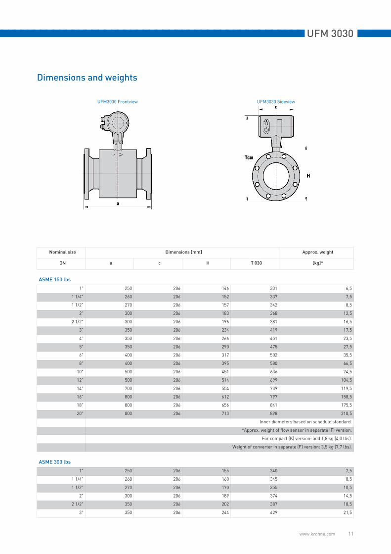
Dimensions and weights
UFM3030 Frontview UFM3030 Sideview
Nominal size Dimensions [mm] Approx. weight
DN a c H T 030 [kg]*
ASME 150 lbs
1" 250 206 146 331 6,5
1 1/4" 260 206 152 337 7,5
1 1/2" 270 206 157 342 8,5
2" 300 206 183 368 12,5
2 1/2" 300 206 196 381 16,5
3" 350 206 234 419 17,5
4" 350 206 266 451 23,5
5" 350 206 290 475 27,5
6" 400 206 317 502 35,5
8" 400 206 395 580 66,5
10" 500 206 451 636 74,5
12" 500 206 514 699 104,5
14" 700 206 554 739 119,5
16" 800 206 612 797 158,5
18" 800 206 656 841 175,5
20" 800 206 713 898 210,5
Inner diameters based on schedule standard.
*Approx. weight of flow sensor in separate (F) version.
For compact (K) version: add 1,8 kg (4,0 lbs).
Weight of converter in separate (F) version: 3,5 kg (7,7 lbs).
ASME 300 lbs
1" 250 206 155 340 7,5
1 1/4" 260 206 160 345 8,5
1 1/2" 270 206 170 355 10,5
2" 300 206 189 374 14,5
2 1/2" 350 206 202 387 18,5
3" 350 206 244 429 21,5

UFM 3030 nnnnnnnnnnnnnnnnnnnnnnnnnnnnnnnnnnnnnnnnnnnnnnnn
www.krohne.com 12
4" 400 206 279 464 32,5
5" 400 206 303 488 41,5
6" 450 206 336 521 53,5
Inner diameters based on schedule standard.
*Approx. weight of flow sensor in separate (F) version.
For compact (K) version: add 1,8 kg (4,0 lbs).
Weight of converter in separate (F) version: 3,5 kg (7,7 lbs).
DIN
25 250 206 150 335 6,5
32 260 206 162 347 8,5
40 270 206 167 352 9,5
50 300 206 190 375 12,5
65 300 206 200 385 15,5
80 300 206 239 424 16,5
100 350 206 262 447 18,5
125 350 206 288 473 22,5
150 350 206 320 505 27,5
200 400 206 394 579 50,5
250 400 206 445 630 60,5
300 500 206 495 680 75,5
350 500 206 540 725 68,5
400 600 206 595 780 89,5
500 600 206 697 882 117,5
Inner diameters based on schedule standard.
*Approx. weight of flow sensor in separate (F) version.
For compact (K) version: add 1,8 kg (4,0 lbs).
Weight of converter in separate (F) version: 3,5 kg (7,7 lbs).
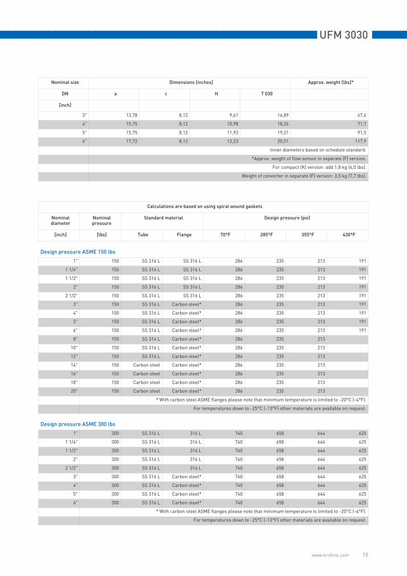
Calculations are based on using spiral wound gaskets
Nominaldiameter
Nominalpressure
Standard material Design pressure (bar)
[inch] [lbs] Tube Flange 20°C 140°C 180°C 220°C
Design pressure ASME 150 lbs
1" 150 SS 316 L SS 316 L 19,7 16,2 14,7 13,2
1 1/4" 150 SS 316 L SS 316 L 19,7 16,2 14,7 13,2
1 1/2" 150 SS 316 L SS 316 L 19,7 16,2 14,7 13,2
2" 150 SS 316 L SS 316 L 19,7 16,2 14,7 13,2
2 1/2" 150 SS 316 L SS 316 L 19,7 16,2 14,7 13,2
3" 150 SS 316 L Carbon steel* 19,7 16,2 14,7 13,2
4" 150 SS 316 L Carbon steel* 19,7 16,2 14,7 13,2
5" 150 SS 316 L Carbon steel* 19,7 16,2 14,7 13,2
6" 150 SS 316 L Carbon steel* 19,7 16,2 14,7 13,2
8" 150 SS 316 L Carbon steel* 19,7 16,2 14,7
10" 150 SS 316 L Carbon steel* 19,7 16,2 14,7
12" 150 SS 316 L Carbon steel* 19,7 16,2 14,7
14" 150 Carbon steel Carbon steel* 19,7 16,2 14,7
16" 150 Carbon steel Carbon steel* 19,7 16,2 14,7
Nominal size Dimensions [mm] Approx. weight
DN a c H T 030 [kg]*

nnnnnnnnnnnnnnnnnnnnnnnnnnnnnnnnnnnnnnnnnnnnnnnn UFM 3030
www.krohne.com 13
18" 150 Carbon steel Carbon steel* 19,7 16,2 14,7
20" 150 Carbon steel Carbon steel* 19,7 16,2 14,7
* With carbon steel ASME flanges please note that minimum temperature is limited to -20°C (-4°F).
For temperatures down to -25°C (-13°F) other materials are available on request.
Design pressure ASME 300 lbs
1" 300 SS 316 L 316 L 51 45,4 44,4 43,1
1 1/4" 300 SS 316 L 316 L 51 45,4 44,4 43,1
1 1/2" 300 SS 316 L 316 L 51 45,4 44,4 43,1
2" 300 SS 316 L 316 L 51 45,4 44,4 43,1
2 1/2" 300 SS 316 L 316 L 51 45,4 44,4 43,1
3" 300 SS 316 L Carbon steel* 51 45,4 44,4 43,1
4" 300 SS 316 L Carbon steel* 51 45,4 44,4 43,1
5" 300 SS 316 L Carbon steel* 51 45,4 44,4 43,1
6" 300 SS 316 L Carbon steel* 51 45,4 44,4 43,1
* With carbon steel ASME flanges please note that minimum temperature is limited to -20°C (-4°F).
For temperatures down to -25°C (-13°F) other materials are available on request.
Design pressure DIN
25 40 SS 316 L SS 316 40 33,7 31,6 29,5
32 40 SS 316 L SS 316 40 33,7 31,6 29,5
40 40 SS 316 L SS 316 40 33,7 31,6 29,5
50 40 SS 316 L SS 316 40 33,7 31,6 29,5
65 40 SS 316 L SS 316 40 33,7 31,6 29,5
80 40 SS 316 L Carbon steel* 40 33,7 31,6 29,5
100 16 SS 316 L Carbon steel* 16 12,7 11,6 10,5
125 16 SS 316 L Carbon steel* 16 12,7 11,6 10,5
150 16 SS 316 L Carbon steel* 16 12,7 11,6 10,5
200 10 SS 316 L Carbon steel* 10 7,8 7,1
250 10 SS 316 L Carbon steel* 10 7,8 7,1
300 10 SS 316 L Carbon steel* 10 7,8 7,1
350 10 Carbon Steel Carbon steel* 10 7,8 7,1
400 10 Carbon Steel Carbon steel* 10 7,8 7,1
500 10 Carbon Steel Carbon steel* 10 7,8 7,1
* With carbon steel DIN flanges please note that minimum temperature is limited to -10°C.
For temperatures down to -25°C other materials are available on request.
Calculations are based on using spiral wound gaskets
Nominaldiameter
Nominalpressure
Standard material Design pressure (bar)
[inch] [lbs] Tube Flange 20°C 140°C 180°C 220°C
UFM 3030 nnnnnnnnnnnnnnnnnnnnnnnnnnnnnnnnnnnnnnnnnnnnnnnn
www.krohne.com 14
UFM3030 Frontview UFM3030 Sideview
Nominal size Dimensions [inches] Approx. weight [lbs]*
DN a c H T 030
[inch]
ASME 150 lbs
1" 9,84 8,12 5,75 13,03 14,3
1 1/4" 10,24 8,12 5,98 13,26 16,5
1 1/2" 10,63 8,12 6,18 13,46 18,7
2" 11,81 8,12 7,2 14,48 27,6
2 1/2" 11,81 8,12 7,71 14,99 36,4
3" 13,78 8,12 9,21 16,49 38,6
4" 13,78 8,12 10,47 17,75 51,8
5" 13,78 8,12 11,42 18,7 60,6
6" 15,75 8,12 12,48 19,76 78,3
8" 15,75 8,12 15,55 22,83 146,6
10" 19,69 8,12 17,76 25,04 164,2
12" 19,69 8,12 20,24 27,52 230,4
14" 27,56 8,12 21,81 29,09 263,5
16" 31,5 8,12 24,09 31,37 349,4
18" 31,5 8,12 25,83 33,11 386,9
20" 31,5 8,12 28,07 35,35 464,1
Inner diameters based on schedule standard.
*Approx. weight of flow sensor in separate (F) version.
For compact (K) version: add 1,8 kg (4,0 lbs).
Weight of converter in separate (F) version: 3,5 kg (7,7 lbs).
ASME 300 lbs
1" 9,84 8,12 6,1 13,38 16,5
1 1/4" 10,24 8,12 6,3 13,58 18,7
1 1/2" 10,63 8,12 6,69 13,97 23,1
2" 11,81 8,12 7,44 14,72 32
2 1/2" 13,78 8,12 7,95 15,23 40,8
nnnnnnnnnnnnnnnnnnnnnnnnnnnnnnnnnnnnnnnnnnnnnnnn UFM 3030
www.krohne.com 15
3" 13,78 8,12 9,61 16,89 47,4
4" 15,75 8,12 10,98 18,26 71,7
5" 15,75 8,12 11,93 19,21 91,5
6" 17,72 8,12 13,23 20,51 117,9
Inner diameters based on schedule standard.
*Approx. weight of flow sensor in separate (F) version.
For compact (K) version: add 1,8 kg (4,0 lbs).
Weight of converter in separate (F) version: 3,5 kg (7,7 lbs).
Calculations are based on using spiral wound gaskets
Nominaldiameter
Nominalpressure
Standard material Design pressure (psi)
[inch] [lbs] Tube Flange 70°F 285°F 355°F 430°F
Design pressure ASME 150 lbs
1" 150 SS 316 L SS 316 L 286 235 213 191
1 1/4" 150 SS 316 L SS 316 L 286 235 213 191
1 1/2" 150 SS 316 L SS 316 L 286 235 213 191
2" 150 SS 316 L SS 316 L 286 235 213 191
2 1/2" 150 SS 316 L SS 316 L 286 235 213 191
3" 150 SS 316 L Carbon steel* 286 235 213 191
4" 150 SS 316 L Carbon steel* 286 235 213 191
5" 150 SS 316 L Carbon steel* 286 235 213 191
6" 150 SS 316 L Carbon steel* 286 235 213 191
8" 150 SS 316 L Carbon steel* 286 235 213
10" 150 SS 316 L Carbon steel* 286 235 213
12" 150 SS 316 L Carbon steel* 286 235 213
14" 150 Carbon steel Carbon steel* 286 235 213
16" 150 Carbon steel Carbon steel* 286 235 213
18" 150 Carbon steel Carbon steel* 286 235 213
20" 150 Carbon steel Carbon steel* 286 235 213
* With carbon steel ASME flanges please note that minimum temperature is limited to -20°C (-4°F).
For temperatures down to -25°C (-13°F) other materials are available on request.
Design pressure ASME 300 lbs
1" 300 SS 316 L 316 L 740 658 644 625
1 1/4" 300 SS 316 L 316 L 740 658 644 625
1 1/2" 300 SS 316 L 316 L 740 658 644 625
2" 300 SS 316 L 316 L 740 658 644 625
2 1/2" 300 SS 316 L 316 L 740 658 644 625
3" 300 SS 316 L Carbon steel* 740 658 644 625
4" 300 SS 316 L Carbon steel* 740 658 644 625
5" 300 SS 316 L Carbon steel* 740 658 644 625
6" 300 SS 316 L Carbon steel* 740 658 644 625
* With carbon steel ASME flanges please note that minimum temperature is limited to -20°C (-4°F).
For temperatures down to -25°C (-13°F) other materials are available on request.
Nominal size Dimensions [inches] Approx. weight [lbs]*
DN a c H T 030
[inch]
UFM 3030 nnnnnnnnnnnnnnnnnnnnnnnnnnnnnnnnnnnnnnnnnnnnnnnn
www.krohne.com 16
KROHNE Overview
Addresses:
Germany
Northern sales office
KROHNE Messtechnik GmbH & Co. KG Bremer Str. 133 D-21073 Hamburg Phone:+49 (0)40 767 3340 Fax:+49 (0)40 767 33412 [email protected] ZIP code: 10000 - 29999, 49000 - 49999
Western and middle sales office
KROHNE Messtechnik GmbH & Co. KG Ludwig-Krohne-Straße D-47058 Duisburg Phone:+49 (0)203 301 416 Fax:+49 (0)203 301 10416 [email protected] ZIP code: 30000 - 34999, 37000 - 48000, 50000 - 53999, 57000 - 59999, 98000 - 99999
Southern sales office
KROHNE Messtechnik GmbH & Co. KG Landsberger Str. 392 D-81241 Munich Phone:+49 (0)89 121 5620 Fax:+49 (0)89 129 6190 [email protected] code: 0 - 9999, 80000 - 89999, 90000 - 97999
Southwestern sales office
KROHNE Messtechnik GmbH & Co. KG Rüdesheimer Str. 40 D-65239 Hochheim/Main Phone: +49(0)6146) 827 30 Fax:+49 (0)6146 827 312 [email protected] ZIP code: 35000 - 36999, 54000 - 56999, 60000 - 79999
Instrumentation and control
equipment catalog
TABLAR Messtechnik GmbH Ludwig-Krohne-Straße 5D-47058 Duisburg Phone:+49 (0)2 03 305 880 Fax:+49 (0)2 03 305 8888 [email protected] www.tablar.de
KROHNE sales
companies
International
Australia
KROHNE Australia Pty Ltd Quantum Business Park 10/287 Victoria Rd Rydalmere NSW 2116 Phone: +61 2 8846 1700 Fax: +61 2 8846 1755 [email protected]
Austria
KROHNE Austria Ges.m.b.H.Modecenterstraße 14A-1030 ViennaPhone:+43 (0)1/203 45 32Fax:+43 (0)1/203 47 [email protected]
Belgium
KROHNE Belgium N.V.Brusselstraat 320 B-1702 Groot Bijgaarden Phone:+32 (0)2 4 66 00 10 Fax:+32 (0)2 4 66 08 00 [email protected]
Brazil
KROHNE Conaut Controles Automaticos Ltda. Estrada Das Águas Espraiadas, 230 C.P. 56 06835 - 080 EMBU - SP Phone:+55 (0)11-4785-2700 Fax:+55 (0)11 4785-2768 [email protected]
China
KROHNE Measurement Instruments (Shanghai) Co. Ltd., (KMIC)Room 15011033 Zhaojiabang RoadShanghai 200030Phone: +86 21 6487 9611Fax:+86 21 6438 [email protected]
Czech Republic
Sobíšická 15663800 BrnoPhone: +420 (0)545.242 627Fax: +420 (0)545 220 093 [email protected]
France
KROHNE S.A.S.Les Ors BP 98F-26103 ROMANS CedexPhone:+33 (0)4 75 05 44 00Fax:+33 (0)4 75 05 00 [email protected]
Great Britain
KROHNE Ltd.Rutherford Drive Park Farm Industrial Estate WellingboroughNorthants NN8 6AEPhone:+44 (0)19 33 408 500Fax:+44 (0)19 33 408 [email protected]
CIS
Kanex KROHNE Engineering AGBusiness-Centre PlanetaOffice 404 ul.Marxistskaja 3109147 Moscow/RussiaPhone:+7 (0)095 911 7165Fax:+7 (0)095 742 [email protected]
India
Krohne Marshall Ltd. A-34/35, M.I.D.C. Industrial Area,H-BlockPimpri Poona 411018Phone:+91 (0)202 744 2020Fax:+91 (0)202 744 [email protected]
Iran
KROHNE Liaison OfficeNorth Sohrevardi Ave. 26,Sarmad St., Apt. #9Tehran 15539Phone: +9821 8874 5973Fax: +9821 8850 [email protected]
Italy
KROHNE Italia Srl. Via V. Monti 75I-20145 MilanPhone:+39 (0)2 43 30 06 61Fax:+39 (0)2 43 00 66 [email protected]
Korea
KROHNE KoreaRoom 508 Miwon Bldg 43Yoido-Dong Youngdeungpo-KuSeoul, KoreaPhone: 00-82-2-780-1743Fax: [email protected]
Netherlands
KROHNE Nederland B.V.Kerkeplaat 14NL-3313 LC DordrechtPhone:+31 (0)78 630 6200Fax:+31 (0)78 630 6405Service Direct: +31 (0)78 630 [email protected]
Norway
KROHNE Norway A.S. Ekholtveien 114NO-1521 MossPhone:+47 (0)69 264 860Fax:+47 (0)69 267 [email protected]
Poland
KROHNE Endra Sp.z.o.o.ul. Stary Rynek Oliwsiki 8a80-324 GdanskPhone: +48 (0)58 520 9211Fax.:+48 (0)58 520 [email protected]
Switzerland
KROHNE AGUferstr. 90CH-4019 BaselPhone:+41 (0)61 638 30 30Fax:+41 (0)61 638 30 [email protected]
Singapore
Tokyo Keiso - KROHNE (Singapore) Pte. Ltd.14, International Business Park, Jurong EastChiyoda Building, #01-01/02Singapore 609922Phone: (65) 6567 4548Fax : (65) 6567 [email protected]
Republic of South Africa
KROHNE Pty. Ltd.163 New RoadHalfway House Ext 13MidrandPhone: +27 (0)11 315 2685Fax: +27 (0)11 805 [email protected]
Spain
I.I. KROHNE IBERIA, S.r.l.Poligono Industrial NiloCalle Brasil, nº. 528806 Alcalá de Henares MadridPhone: +34 (0)91 883 2152Fax: +34 (0)91 883 4854 [email protected]
USA
KROHNE, Inc.7 Dearborn RoadPeabody, MA 01960Phone: +1 (800) FLOWINGPhone: +1 (978) 535 6060 (in MA)[email protected]
Representatives
Algeria ArgentinaCameroonCanadaChileColumbiaCroatiaDenmarkEcuadorEgyptFinlandGabonGhanaGreeceHong KongHungaryIndonesiaIranIrelandIsraelIvory CoastJapanJordanKuwaitLibyaLithuaniaMalaysiaMauritiusMexicoMoroccoNew ZealandPeruPortugalRomaniaSaudi ArabiaSenegalSlovakiaSlovenia SwedenTaiwan ThailandTunisiaTurkeyVenezuelaYugoslavia
Other countries
KROHNE Messtechnik GmbH & Co. KG Ludwig-Krohne-Str. 5D-47058 Duisburg Phone:+49 (0)203 301 0Fax:+49 (0)203 301 389 [email protected]
• Electromagnetic flowmeters • Level measuring instruments
• Variable area flowmeters • Pressure gauges
• Mass flowmeters • Temperature measuring instruments
• Ultrasonic flowmeters • Water solutions & analysis
• Vortex flowmeters • Oil and gas turnkey solutions
• Flow controllers
© K
RO
HN
E0
4/2
00
67
.02
39
0.2
7.0
0ch
an
ge
s r
es
erv
ed


![UFM 3030 - corame.fr€¦ · UFM 3030 nnnnnnnnnnnnnnnnnnnnnnnnnnnnnnnnnnnnnnnnnnnnnnnn 6 Capteur à ultrasons UFS 3000 Diamètre nominal ASME [pouces] 1" 1 ¼" 1,5"](https://img.pdfslide.net/doc/110x75/5b5d2abb7f8b9ad21d8d9bba/ufm-3030-ufm-3030-nnnnnnnnnnnnnnnnnnnnnnnnnnnnnnnnnnnnnnnnnnnnnnnn-6-capteur.jpg)