Embed Size (px)
Citation preview

© A
BB P
ower
Tec
hnol
ogie
s.Po
wer
Sys
tem
s D
C -
1
abb.com/hvdc
UHVDC WorkshopDelhi
2005-02-25, 26
UHVDC EquipmentUrban Astrom

© A
BB P
ower
Tec
hnol
ogie
sPo
wer
Sys
tem
s D
C -
2 -
What has been done by ABB?
What has been done by ABB?! Itaipu ±600 kV HVDC transmission system in operation since 1985, forced energy
unavailability 0.05% year 2000, both bipoles! Cooperation with NIIPT on UHVDC since 1988! STRI test laboratory established in 1991 for UHVDC research! 800 kV HVDC project started in cooperation with Eletrobras/CEPEL/Furnas 1993
(system studies, design and tests of equipment)! New tools for calculation of stresses in oil/paper insulation systems developed,
based on ion conduction model
! 800 kV HVDC equipment successfully tested 1994! Wall bushing (oil porcelain)! Support and string insulators

© A
BB P
ower
Tec
hnol
ogie
sPo
wer
Sys
tem
s D
C -
3 -
Resistive voltage distribution
! When applicable, DC equipment is built up by modules with resistive voltage distribution between the modules, controlled by actual resistors
! With a proper voltage grading, each module will experience the same stress at 800 as at 500 kV pole voltage
! This is valid for:! Thyristor valves! Pole arresters! Voltage dividers! DC PLC capacitors! DC harmonic capacitors
! For outdoor equipment there must be a proper coordination between internal and external voltage distribution (PLC-capacitors, DC voltage divider)

© A
BB P
ower
Tec
hnol
ogie
sPo
wer
Sys
tem
s D
C -
4 -
Thyristor Valve Layout
TCU Derivative Feeding Resistor
Thyristor
Saturable ReactorModule
TCU
Thyristor Module
DC GradingResistor
Damping Resistors
Damping Capacitors
TCU DerivativeFeeding Capacitor
TCU
TCU
TCUThyristorControl Unit
© A
BB P
ower
Tec
hnol
ogie
sPo
wer
Sys
tem
s D
C -
5 -
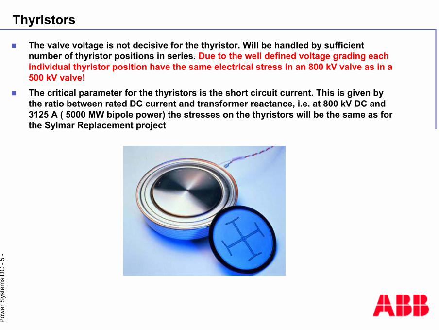
Thyristors
! The valve voltage is not decisive for the thyristor. Will be handled by sufficient number of thyristor positions in series. Due to the well defined voltage grading each individual thyristor position have the same electrical stress in an 800 kV valve as in a 500 kV valve!
! The critical parameter for the thyristors is the short circuit current. This is given by the ratio between rated DC current and transformer reactance, i.e. at 800 kV DC and 3125 A ( 5000 MW bipole power) the stresses on the thyristors will be the same as for the Sylmar Replacement project

© A
BB P
ower
Tec
hnol
ogie
sPo
wer
Sys
tem
s D
C -
6 -
Experience of 14000 5� thyristors
3650@20°C
3100200420163100Sylmar Replacement PprojectUSA
3555@20°C
3000200441763000Three Gorges-Guandong, China
-392020033362x100Rapid CityUSA
3555@20°C
3000200341763000Three Gorges-Changzhou, China
-4020200217281100Garabi 2Brazil
-4020200017281100Garabi 1Brazil
Overload Current, A
Nominal Current, A
Commis-sioned year
Number of thyristors
PowerTransmitted,
MW
Project
No thyristor failure during commercial operation reported

© A
BB P
ower
Tec
hnol
ogie
sPo
wer
Sys
tem
s D
C -
7 -
800 kV valve hall
Air clearance in the valve hall will be influenced. This can be calculated using 3-D field calculation programs. The clearances will be verified at the type test of the valve.

© A
BB P
ower
Tec
hnol
ogie
sPo
wer
Sys
tem
s D
C -
8 -
Valve hall clearance
U50 for Positive switching impulse for different electrode geometry

© A
BB P
ower
Tec
hnol
ogie
sPo
wer
Sys
tem
s D
C -
9 -
Resistive voltage distribution: DC filter capacitors
The stresses across the groups of parallel connected elements are controlled by the voltage distribution across the grading resistors.
The grading current is of mA order of magnitude.

© A
BB P
ower
Tec
hnol
ogie
sPo
wer
Sys
tem
s D
C -
10 -
DC harmonic filter capacitor 800 kV
3GC 500 kVDC capacitor

© A
BB P
ower
Tec
hnol
ogie
sPo
wer
Sys
tem
s D
C -
11 -
DC pole arrester for 800 kV

© A
BB P
ower
Tec
hnol
ogie
sPo
wer
Sys
tem
s D
C -
12 -
Transformer main insulation
! The volume is divided into sub volumes by insulation barriers to eliminate the effect of large volumes
! The local electric stress in each region will be kept at a safe level
! Since the resistivity of oil and paper depend on temperature and time, the worst possible combinations of parameters will be considered
! Both transient, AC and steady state conditions will be considered
! Both electron conduction and ion conduction must be considered
The main insulation for the transformer is split up in parts, in analogy with for example the thyristor valves:
The separate sub volumes do not know whether they are inside a 800 kV converter transformer or in a 500 kV transformer!

© A
BB P
ower
Tec
hnol
ogie
sPo
wer
Sys
tem
s D
C -
13 -
800 kV HVDC converter transformer and transformer bushings
© A
BB P
ower
Tec
hnol
ogie
sPo
wer
Sys
tem
s D
C -
14 -
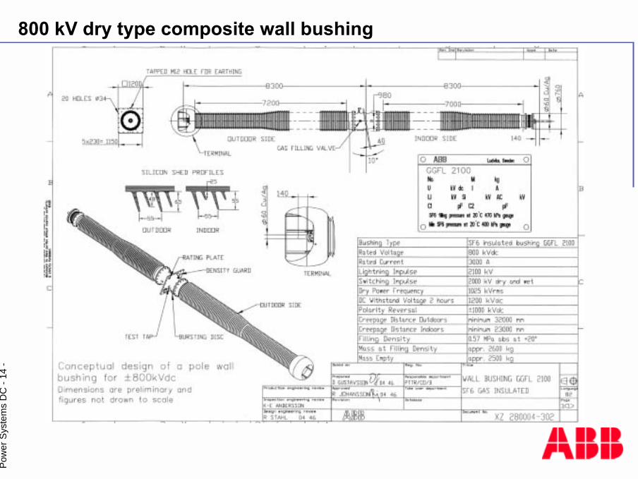
800 kV dry type composite wall bushing
© A
BB P
ower
Tec
hnol
ogie
sPo
wer
Sys
tem
s D
C -
15 -
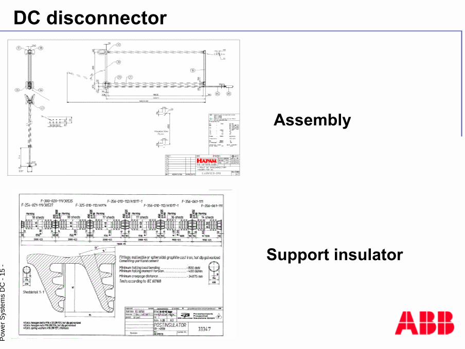
DC disconnector
Assembly
Support insulator
© A
BB P
ower
Tec
hnol
ogie
sPo
wer
Sys
tem
s D
C -
16 -
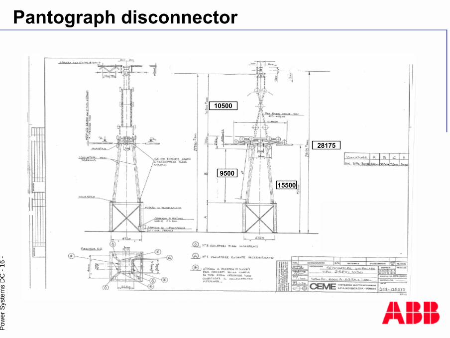
Pantograph disconnector
28175
15500
10500
9500

© A
BB P
ower
Tec
hnol
ogie
sPo
wer
Sys
tem
s D
C -
17 -
Test voltages for equipment
N.A.1040(3 hrs)
N.A.15181800Thyristor multiple valve
103012351000(one minute)
15181800Wall bushing
N.A.N.A.N.A.15461950PLC capacitor
N.A.N.A.N.A.15461950Disconnecting switch
N.A.N.A.1000(one minute)
15461950Voltage divider
N.A.N.A.N.A.15461950
N.A.N.A.N.A.N.A.2160/2Smoothing reactor, Across
To ground
970125090015181744Transformer bushing, valve side
970125090015181744Converter transformer, Valve side
DCPolarity reversal
DCACRMSSILIEquipment
© A
BB P
ower
Tec
hnol
ogie
sPo
wer
Sys
tem
s D
C -
18 -
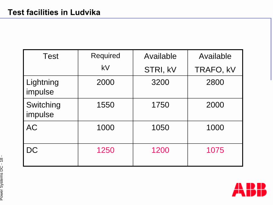
Test facilities in Ludvika
107512001250DC
100010501000AC
200017501550Switching impulse
280032002000Lightning impulse
AvailableTRAFO, kV
AvailableSTRI, kV
RequiredkV
Test

© A
BB P
ower
Tec
hnol
ogie
sPo
wer
Sys
tem
s D
C -
19 -
UHVDC- proposed test circuit
Transformer dummy
DC voltage generator (800 kV dc)
Supportinsulator
Wall bushing
DC test line
Voltage Divider
PLCCapacitor
ArresterIsolating
switch
Suspensioninsulator

ABB

© A
BB P
ower
Tec
hnol
ogie
sPo
wer
Sys
tem
s D
C -
21 -
Experience high current
--Air core 2x50 mH
192MVA1φ/3W
393070Garabi BtB
--Oil filled 40 mH
156MVA 3φ/2W
360070Vindhyachal BtB
--Air core 12 mH
240MVA3φ/3W
360057Highgate BtB
Hapam 4000A
Si rubberAir core 2x50 mH
620MVA 1φ/3W
3100±500Sylmar replacement
Cegelec 4000 A
Si rubberOil filled 270 mH
300MVA1φ/2W
3000±5003GC/3GG
Hapam 3600 A
Porcelain(Si greased)
Air core 2X150 mH
402MVA 1φ/3W
2260±500HQ/NEH
Southern States 4000A
PorcelainOil filled 300 mH
305MVA1φ/3W
1920±500IPP
PorcelainOil filled278 mH
314MVA1φ/3W
2610±600Itaipu
DC connectorWall bushing
SmoothingReactor
TrafoIdc
AUdc
kv


![[Karl J. Astrom, Bjorn Wittenmark] Adaptive Contro(BookZa.org)](https://img.pdfslide.net/doc/110x75/55cf8eb9550346703b94f09e/karl-j-astrom-bjorn-wittenmark-adaptive-controbookzaorg.jpg)