Embed Size (px)
Citation preview
((&6 6SULQJ /HFWXUH & 7 &KRL
Thévenin & Norton Equivalent Circuits
Lecture 5 review:
• Voltage divider & current divider
• Equivalent circuits (Thévenin & Norton equivalents)
Today: (3.3, 3.4)
• Power Calculations
• Starting your car (model)
((&6 6SULQJ /HFWXUH & 7 &KRL
RESISTORS IN SERIES
Circuit with several resistors in series – Can we find an equivalent resistance?
.&/ WHOOV XV VDPH FXUUHQW
IORZV WKURXJK HYHU\ UHVLVWRU
.9/ WHOOV XV
6695,5,5,5, =⋅+⋅+⋅+⋅
&OHDUO\
55559,66
+++=
) 7KXV HTXLYDOHQW UHVLVWDQFH RI UHVLVWRUV LQ VHULHV LV WKH VLPSOH VXP
R2
R1
VSS
I ?
R3
R4
−+
(Here its more convenient to use KVL than node analysis)
((&6 6SULQJ /HFWXUH & 7 &KRL
GENERALIZED VOLTAGE DIVIDER
Circuit with several resistors in series
R 2
R 1
VSS
I
R 3
R 4
−+ −
+
−+ V1
V3
• We know
55559,66
+++=
• Thus,
66
9
5555
59 ⋅
+++=
and
66
9
5555
59 ⋅
+++=
HWF HWF
((&6 6SULQJ /HFWXUH & 7 &KRL
WHEN IS VOLTAGE DIVIDER FORMULA CORRECT?
R2
R1
V SS
I
R3
R4
−+ −
+
66
9
5555
59 j
+++=
Correct if nothing elseconnected to nodes
3
VSS
i
R2
R1
R3
R4
−+ −
+9
R5i
X
66
9
5555
59 j
+++≠
because R5 removes condition ofresistors in series – i.e. ,L ≠
What is V2? Answer: 66
955555
5j
+++
V2
((&6 6SULQJ /HFWXUH & 7 &KRL
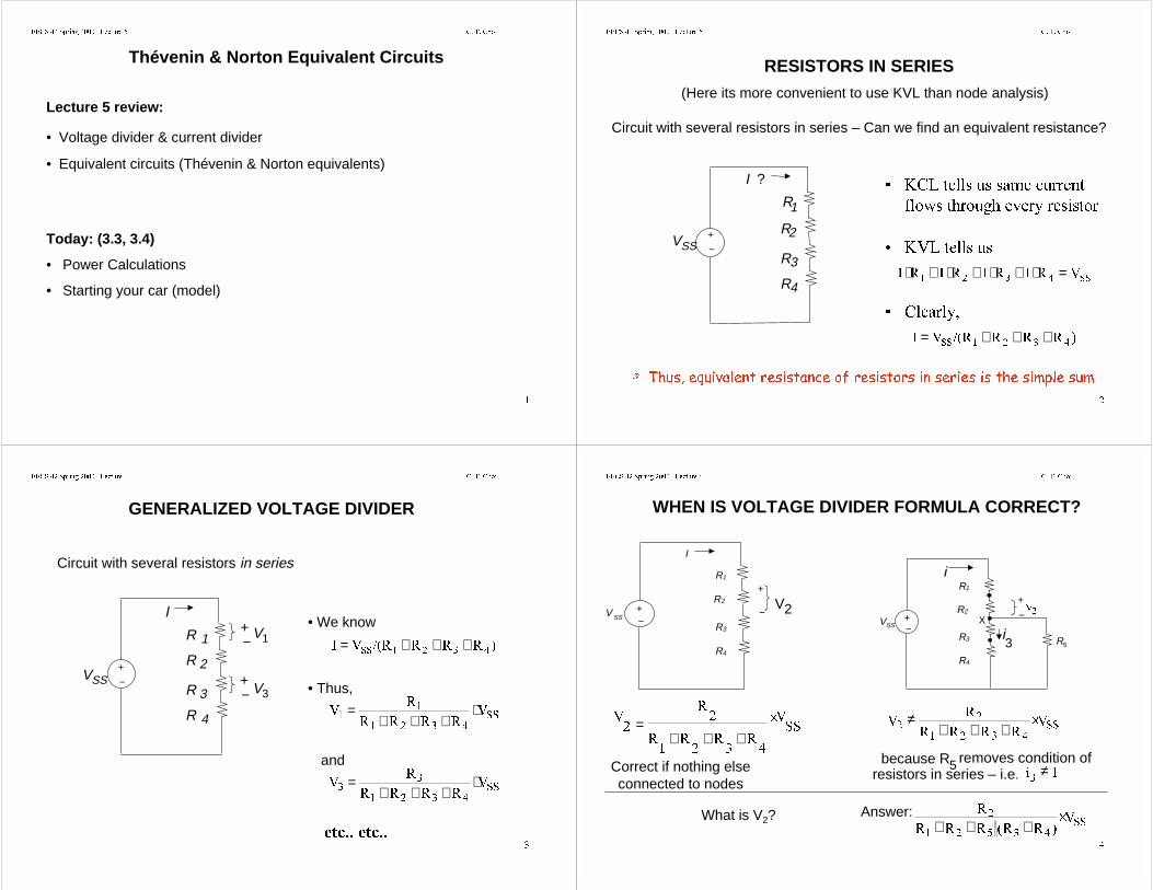
RESISTORS IN PARALLEL
R2R1 ISS
I2I12 Define unknown node voltages
VX
1 Select Reference Node
66;
5
5
,9
+⋅=⇒
Note: Iss = I1 + I2, i.e.,
;
;66
5
9
5
9, +=
66
55
55,
+⋅=
RESULT 1 EQUIVALENT RESISTANCE:
__
55
555__55
+=≡
RESULT 2 CURRENT DIVIDER:
66
;
66
;
55
5,
5
9,
55
5,
5
9,
+×==
+×==
((&6 6SULQJ /HFWXUH & 7 &KRL
REAL VOLTMETERSConcept of “Loading” as Application of Parallel Resistors
How is voltage measured? Modern answer: Digital multimeter (DMM)
Problem: Connecting leads from voltmeter across two nodes changesthe circuit. The voltmeter is characterized by how much current itdraws at a given voltage Æ “voltmeter input resistance,” Rin. Typicalvalue: 10 MΩ
+
=
6655
599
+=′
LQ
LQ66
55__5
5__599
−+
VSS
R1
R2 Rin
+
−9′
Example: 99.5.599 66 =⇒===
−+
VSS
R1
R2
+
−
V2
But if 9905 LQ =′= a 1% error
((&6 6SULQJ /HFWXUH & 7 &KRL
GENERALIZED PARALLEL RESISTORS
What single resistance Req is equivalent to three resistors in parallel?
−
9
,
9
−
,
555 5HT
HT≡
HT 5
9
5
9
5
9
5
9, ≡++=
HT
5
5
5
5__5__55
++=≡⇒
Note the simplicity if we use conductance instead of resistance
HTHT
5
*HWF
5
* ≡≡
Then, HT **** ++= ADD CONDUCTANCES IN PARALLEL
((&6 6SULQJ /HFWXUH & 7 &KRL
GENERALIZED CURRENT DIVIDER
Can we getthis result byinspection?
Current splits among M resistorsin parallel R2R1
II2I1 I3
R3
−
9
YES – Consider R1||R2 as “one equivalent resistor”
+
+
=
5
5
5
,9
++
==
555
5,
5
9,
++
+=
55555
5555,
,55__5
5__5,7KHQ
×
+= ,
55555
5555
×++
+=
)RUPDODSSURDFK
++
=
555555
55,,
++
=
***
*,,1RWH
((&6 6SULQJ /HFWXUH & 7 &KRL
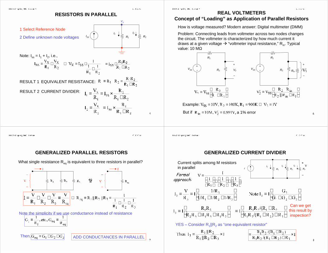
IDENTIFYING SERIES AND PARALLEL COMBINATIONSUse series/parallel equivalents to simplify a circuit before starting KVL/KCL
5
55
HT5
−+
V
I
R
R
R
R
2
1
4
R3
R65
.55 ==
.5 =
.5 ==
.5 =
−+
I
RX ?
;5__555__555 +++=
.=
55 + 5 parallel
HT 55__55 =+
((&6 6SULQJ /HFWXUH & 7 &KRL
IDENTIFYING SERIES AND PARALLEL COMBINATIONS(cont.)
Some circuits must be analyzed (not amenable to simple inspection)
-+ R2
R1
V
I
R4
R3
R5
Special cases:R3 = 0 OR R3 = ∞
5 DQG 5 DUH QRW
LQ VHULHV
5 DQG 5 DUH QRW LQ __
OR IF R3 = ∞ ⇒ (R1 + R5) || (R2 + R4)
5
−
+
5
5
5
9 5
Req = R1 || R2 + R4 || R5Example: R3 = 0 ⇒ R1 || R2; R4 || R5 in series;
((&6 6SULQJ /HFWXUH & 7 &KRL
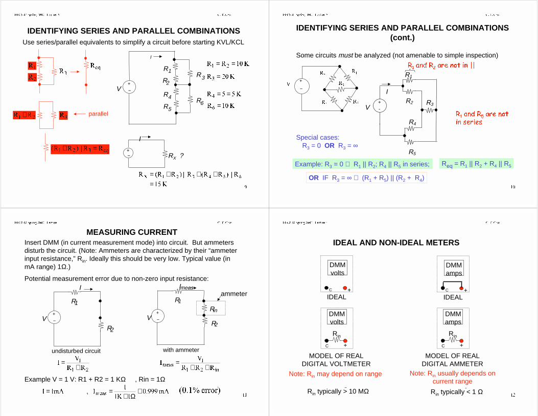
MEASURING CURRENTInsert DMM (in current measurement mode) into circuit. But ammetersdisturb the circuit. (Note: Ammeters are characterized by their “ammeterinput resistance,” Rin. Ideally this should be very low. Typical value (inmA range) 1Ω.)
Potential measurement error due to non-zero input resistance:
Rin
−+
V
Imeas
R1
R2
ammeter
with ammeter
−+
V
I
R1
R2
undisturbed circuit
Example V = 1 V: R1 + R2 = 1 KΩ , Rin = 1Ω
55
9,
+=
LQ
PHDV
555
9,
++=
P$.
,P$, PHDV ≅
Ω+== HUURU
((&6 6SULQJ /HFWXUH & 7 &KRL
IDEAL AND NON-IDEAL METERS
DMMamps
MODEL OF REALDIGITAL AMMETER
C +
Rin
Note: Rin may depend on range Note: Rin usually depends oncurrent range
Rin typically > 10 MΩa
Rin typically < 1 Ωa
C +IDEAL
DMMamps
C +IDEAL
DMMvolts
DMMvolts
MODEL OF REALDIGITAL VOLTMETER
C +
Rin
((&6 6SULQJ /HFWXUH & 7 &KRL
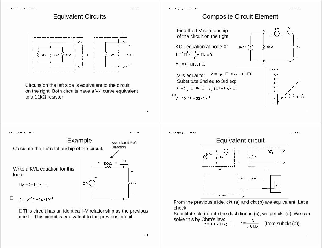
Equivalent Circuits
Circuits on the left side is equivalent to the circuiton the right. Both circuits have a V-I curve equivalent to a 11kΩ resistor.
((&6 6SULQJ /HFWXUH & 7 &KRL
Composite Circuit Element
Find the I-V relationshipof the circuit on the right.
KCL equation at node X:
=+−+−,
99;<
++= ,99<;
V is equal to:Substitute 2nd eq to 3rd eq:
+−=+=<;<;
9999
+=+−++= ,9,99<<
−− ×−= 9,
or
((&6 6SULQJ /HFWXUH & 7 &KRL
ExampleCalculate the I-V relationship of the circuit.
Write a KVL equation for thisloop:
=−−+ ,9
+-
−− ×−= 9,⇒
Associated Ref.Direction
∴This circuit has an identical I-V relationship as the previousone ⇒ This circuit is equivalent to the previous circuit.
((&6 6SULQJ /HFWXUH & 7 &KRL
Equivalent circuit
From the previous slide, ckt (a) and ckt (b) are equivalent. Let’scheck:Substitute ckt (b) into the dash line in (c), we get ckt (d). We cansolve this by Ohm’s law:
5, +=5
,+
=
⇒ (from subckt (b))
((&6 6SULQJ /HFWXUH & 7 &KRL
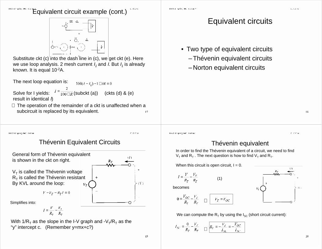
Equivalent circuit example (cont.)
Substitute ckt (c) into the dash line in (c), we get ckt (e). Herewe use loop analysis. 2 mesh current I1 and I. But I1 is alreadyknown. It is equal 10-2A.
The next loop equation is:
Solve for I yields: (subckt (a)) (ckts (d) & (e)result in identical I)
=+−− ,5,,
5,
+=
∴ The operation of the remainder of a ckt is unaffected when a subcircuit is replaced by its equivalent.
((&6 6SULQJ /HFWXUH & 7 &KRL
Equivalent circuits
• Two type of equivalent circuits– Thévenin equivalent circuits– Norton equivalent circuits
((&6 6SULQJ /HFWXUH & 7 &KRL
Thévenin Equivalent Circuits
General form of Thévenin equivalentis shown in the ckt on right.
VT is called the Thévenin voltageRT is called the Thévenin resistantBy KVL around the loop:
=−− ,59977
7
7
75
9
5
9, −=
Simplifies into:
With 1/RT as the slope in the I-V graph and -VT/RT as the “y” intercept c. (Remember y=mx+c?)
((&6 6SULQJ /HFWXUH & 7 &KRL
Thévenin equivalentIn order to find the Thévenin equivalent of a circuit, we need to findVT and RT . The next question is how to find VT and RT.
When this circuit is open circuit, I = 0.
7
7
75
9
5
9, −=
7
7
7
2&
5
9
5
9 −=
becomes
2&799 =⇒
(1)
We can compute the RT by using the ISC (short circuit current):
7
7
7
6&5
9
5, −=
⇒6&
2&
6&
7
7,
9
,
95 −=−=
((&6 6SULQJ /HFWXUH & 7 &KRL
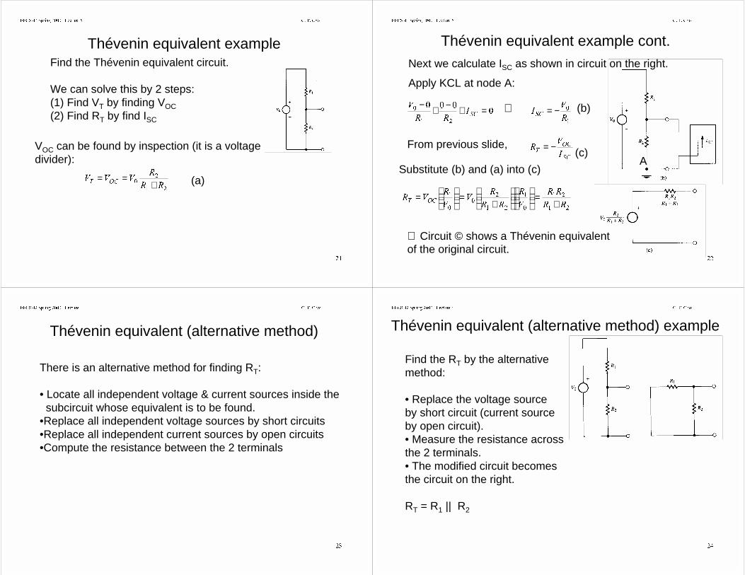
Thévenin equivalent exampleFind the Thévenin equivalent circuit.
We can solve this by 2 steps:(1) Find VT by finding VOC(2) Find RT by find ISC
VOC can be found by inspection (it is a voltagedivider):
55
5999
2&7 +== (a)
((&6 6SULQJ /HFWXUH & 7 &KRL
Thévenin equivalent example cont.Next we calculate ISC as shown in circuit on the right.
A
Apply KCL at node A:
=+−+−6&,
55
9
5
9,6&
−=⇒
From previous slide, 6&
2&
7,
95 −=
55
55
9
5
55
59
9
5952&7 +
=
+
=
=
(b)
Substitute (b) and (a) into (c)
(c)
∴ Circuit © shows a Thévenin equivalentof the original circuit.
((&6 6SULQJ /HFWXUH & 7 &KRL
Thévenin equivalent (alternative method)
There is an alternative method for finding RT:
• Locate all independent voltage & current sources inside the subcircuit whose equivalent is to be found.•Replace all independent voltage sources by short circuits•Replace all independent current sources by open circuits•Compute the resistance between the 2 terminals
((&6 6SULQJ /HFWXUH & 7 &KRL
Thévenin equivalent (alternative method) example
Find the RT by the alternativemethod:
• Replace the voltage sourceby short circuit (current sourceby open circuit).• Measure the resistance acrossthe 2 terminals.• The modified circuit becomesthe circuit on the right.
RT = R1 || R2
((&6 6SULQJ /HFWXUH & 7 &KRL
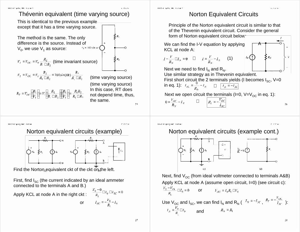
Thévenin equivalent (time varying source)This is identical to the previous exampleexcept that it has a time varying source.
The method is the same. The only difference is the source. Instead ofV0, we use V1 as source:
55
5999
2&7 +==
VLQ
55
5W
55
5999
2&7 +=
+== ω
(time invariant source)
(time varying source)
55
55
9
5
55
59
9
5952&7 +
=
+
=
=
(time varying source)In this case, RT does not depend time, thus,the same.
((&6 6SULQJ /HFWXUH & 7 &KRL
Norton Equivalent Circuits
Principle of the Norton equivalent circuit is similar to thatof the Thevenin equivalent circuit. Consider the generalform of Norton equivalent circuit below:
We can find the I-V equation by applyingKCL at node A:
A
=+−1
1
,5
9,
1
1
,5
9, −=⇒
Next we need to find IN and RN.Use similar strategy as in Thevenin equivalent.First short circuit the 2 terminals yields (I becomes ISC, V=0in eq. 1): 1
1
6&,
5, −=
6&1,, −=⇒
Next we open circuit the terminals (I=0, V=VOC in eq. 1):
(1)
1
1
2&,
5
9 −= ⇒6&
2&
7,
95 −=
((&6 6SULQJ /HFWXUH & 7 &KRL
Norton equivalent circuits (example)
Find the Norton equivalent ckt of the ckt on the left.
First, find ISC (the current indicated by an ideal ammeter connected to the terminals A and B.)
Apply KCL at node A in the right ckt :
=++−6&,,
5
9
,
5
9,6&
−−=or
((&6 6SULQJ /HFWXUH & 7 &KRL
Norton equivalent circuits (example cont.)
Next, find VOC (from ideal voltmeter connected to terminals A&B)
Apply KCL at node A (assume open circuit, I=0) (see circuit c):
=+−,
5
992&
95,9
2&+=or
Use VOC and ISC, we can find IN and RN ( , ):
,
5
9,1
+= 55
1=and
6&1,, −=
6&
2&
7,
95 −=
((&6 6SULQJ /HFWXUH & 7 &KRL
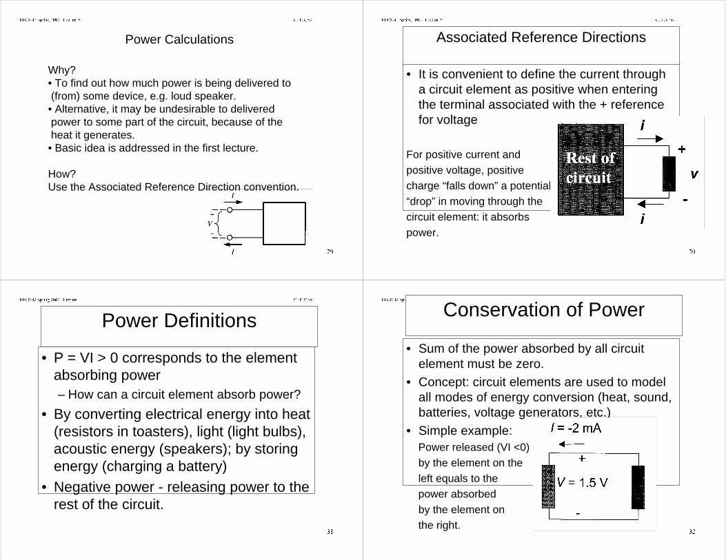
Power Calculations
Why? • To find out how much power is being delivered to (from) some device, e.g. loud speaker.• Alternative, it may be undesirable to delivered power to some part of the circuit, because of the heat it generates.• Basic idea is addressed in the first lecture.
How?Use the Associated Reference Direction convention.
((&6 6SULQJ /HFWXUH & 7 &KRL
Associated Reference Directions
• It is convenient to define the current througha circuit element as positive when enteringthe terminal associated with the + referencefor voltage
For positive current andpositive voltage, positivecharge “falls down” a potential“drop” in moving through thecircuit element: it absorbspower.
((&6 6SULQJ /HFWXUH & 7 &KRL
Power Definitions
• P = VI > 0 corresponds to the elementabsorbing power– How can a circuit element absorb power?
• By converting electrical energy into heat(resistors in toasters), light (light bulbs),acoustic energy (speakers); by storingenergy (charging a battery)
• Negative power - releasing power to therest of the circuit.
((&6 6SULQJ /HFWXUH & 7 &KRL
Conservation of Power
• Sum of the power absorbed by all circuitelement must be zero.
• Concept: circuit elements are used to modelall modes of energy conversion (heat, sound,batteries, voltage generators, etc.)
• Simple example: Power released (VI <0) by the element on the left equals to the power absorbed by the element on the right.
((&6 6SULQJ /HFWXUH & 7 &KRL
Example of Power Flowing into Current Source
What is the power flow into the current source in the circuit onthe right?
Put an imaginary box enclosing the currentsource and apply the associatedreference direction (ARD) to the current source.
(1) Assume V convention on the right, ARD dictates that current has to go into + side of the terminals. By KVL: V = 100mA×(60 Ω +40Ω) = 10V By KCL: I = -100mAThe power entering the box (in this case, current source) is:Power = VI = 10V × -100mA = --1 W ∴1W is leaving the box
((&6 6SULQJ /HFWXUH & 7 &KRL
Example of Power Flowing into Current Source (cont)
(2) Assume V’ convention on the right, ARD dictates that current has to go into + side of the terminals. By KVL: V’ = 100mA×(60 Ω +40Ω) = -10V By KCL: I’ = 100mAThe power entering the box (in this case, current source) is:Power = V’I’ = -10V × 100mA = --1 W ∴1W is leaving the box
Conclusions: V convention does not affect the results. Bothconventions leads to the same conclusion that 1W is leavingthe box or current source.
((&6 6SULQJ /HFWXUH & 7 &KRL
Example of Power Flowing into resistor
Find the power entering the 40 Ω resistoras shown in the circuit.
By associate reference direction convention,the V and I are defined.
By inspection I = 100mA
P = I × V = 100mA × 4V = 0.4W∴0.4W is entering the box (or 40Ω resistor).
(Using the similar strategy, it is found that0.6W is entering the 60Ω resistor.)
9,9 =Ω×=
((&6 6SULQJ /HFWXUH & 7 &KRL
Experimental Measurement of Power using a Volt Source and a Ammeter
The box in the right contains an unknown circuit, experimentally it is found that the I-V diagram as shown. (how? Set the voltage, and measure the current by the ammeter)
V (set) I (measured) P = V I (compute)-3V -18mA +54mW (power entering)-2V -16mA +32mW-1V -14mA +14mW0 -10mA 0 (no power transfer)1V -2mA -2mW (power leaving)2V +20mA +40mW3V +400mA +1.2W∴ In the first and the third quadrant of the I-V curve, power is entering. In the second and the fourth quadrant, power is leaving.
((&6 6SULQJ /HFWXUH & 7 &KRL
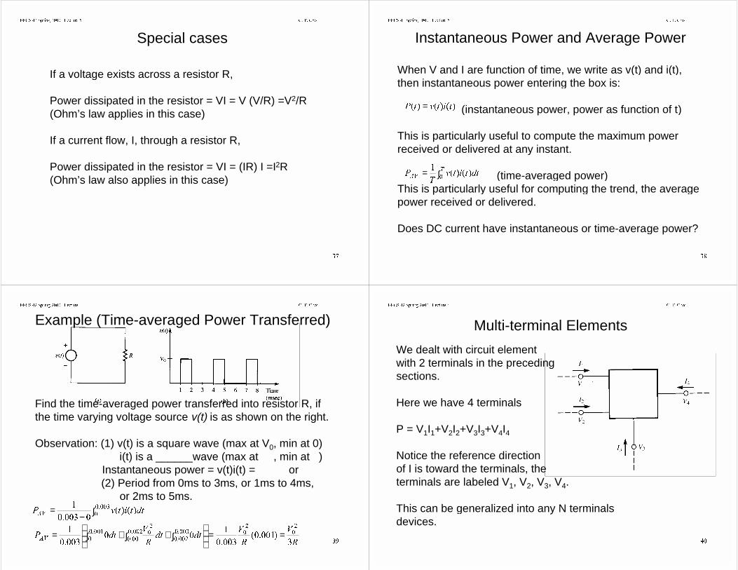
Special cases
If a voltage exists across a resistor R,
Power dissipated in the resistor = VI = V (V/R) =V2/R(Ohm’s law applies in this case)
If a current flow, I, through a resistor R,
Power dissipated in the resistor = VI = (IR) I =I2R(Ohm’s law also applies in this case)
((&6 6SULQJ /HFWXUH & 7 &KRL
Instantaneous Power and Average Power
When V and I are function of time, we write as v(t) and i(t),then instantaneous power entering the box is:
(instantaneous power, power as function of t)
This is particularly useful to compute the maximum powerreceived or delivered at any instant.
(time-averaged power)This is particularly useful for computing the trend, the averagepower received or delivered.
Does DC current have instantaneous or time-average power?
∫= 7
$9GWWLWY
73
WLWYW3 =
((&6 6SULQJ /HFWXUH & 7 &KRL
Find the time-averaged power transferred into resistor R, ifthe time varying voltage source v(t) is as shown on the right.
Observation: (1) v(t) is a square wave (max at V0, min at 0) i(t) is a ______wave (max at , min at )
Instantaneous power = v(t)i(t) = or (2) Period from 0ms to 3ms, or 1ms to 4ms, or 2ms to 5ms.
∫−=
GWWLWY3
$9
5
9
5
9GWGW
5
9GW3
$9
==
∫+∫+∫=
Example (Time-averaged Power Transferred)
((&6 6SULQJ /HFWXUH & 7 &KRL
Multi-terminal Elements
We dealt with circuit elementwith 2 terminals in the precedingsections.
Here we have 4 terminals
P = V1I1+V2I2+V3I3+V4I4
Notice the reference direction of I is toward the terminals, theterminals are labeled V1, V2, V3, V4.
This can be generalized into any N terminalsdevices.
((&6 6SULQJ /HFWXUH & 7 &KRL
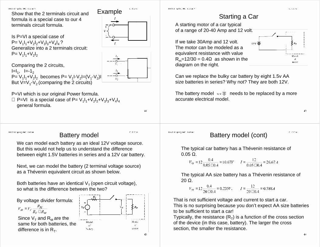
ExampleShow that the 2 terminals circuit and formula is a special case to our 4 terminals circuit formula.
Is P=VI a special case of P= V1I1+V2I2+V3I3+V4I4 ?Generalize into a 2 terminals circuit: P= V1I1+V2I2
Comparing the 2 circuits,I=I1, I=-12P= V1I1+V2I2 becomes P= V1I-V2I=(V1-V2)IBut V=V1-V2 (comparing the 2 circuits)
P=VI which is our original Power formula.∴ P=VI is a special case of P= V1I1+V2I2+V3I3+V4I4 general formula.
((&6 6SULQJ /HFWXUH & 7 &KRL
Starting a CarA starting motor of a car typical of a range of 20-40 Amp and 12 volt.
If we take 30Amp and 12 volt.The motor can be modeled as aequivalent resistance with value Rm=12/30 = 0.4Ω as shown in the diagram on the right.
Can we replace the bulky car battery by eight 1.5v AA size batteries in series? Why not? They are both 12V.
The battery model needs to be replaced by a moreaccurate electrical model.
((&6 6SULQJ /HFWXUH & 7 &KRL
Battery modelWe can model each battery as an ideal 12V voltage source.But this would not help us to understand the difference between eight 1.5V batteries in series and a 12V car battery.
Next, we can model the battery (2 terminal voltage source) as a Thévenin equivalent circuit as shown below.
Both batteries have an identical VT (open circuit voltage),so what is the difference between the two?
By voltage divider formula:
07
0
7055
599
+=
Since VT and RM are the same for both batteries, thedifference is in RT.
((&6 6SULQJ /HFWXUH & 7 &KRL
Battery model (cont)
The typical car battery has a Thévenin resistance of 0.05 Ω.
990
=
+=
The typical AA size battery has a Thévenin resistance of 20 Ω.
99
0=
+=
That is not sufficient voltage and current to start a car.This is no surprising because you don’t expect AA size batteriesto be sufficient to start a car! Typically, the resistance (RT) is a function of the cross sectionof the device (in this case, battery). The larger the cross section, the smaller the resistance.
$,
=+
=
$,
=+
=

((&6 6SULQJ /HFWXUH & 7 &KRL
• Equivalent circuits are circuits that cannot be distinguished fromeach other by measurements at their terminals. Often circuitanalysis can be simplified if a portion of the circuit is replaced bya simpler equivalent. Two general families of equivalents exist forlinear circuits: Thévenin equivalents and Norton equivalents.
• Power flow can be calculated from the expressions P = VI fortwo-terminal circuit elements and P = Σ Vn In for multi-terminalcircuit element. However, it is essential that the signs of thevarious voltages and currents be stated correctly.
• If voltage and current vary, the quantity v(t)i(t) is known as theinstantaneous power. The time-averaged power is the averageover time of the instantaneous power.
Points To Remember:


![Solution Tenta 20160530.ppt [Kompatibilitetsläge] Tenta 20160530.pdf · 2018. 5. 23. · DQG UHVLVWRU 5 7KH GLRGH )'EHFRPHV UHYHUVH ELDVHG DQG WKH FXUUHQW LFRPPXWDWHV WR WKH WUDQVLVWRU](https://img.pdfslide.net/doc/110x75/60a36f30b888e948db1b7874/solution-tenta-kompatibilitetslfge-tenta-20160530pdf-2018-5-23-dqg.jpg)