Embed Size (px)
Citation preview
UINFORMATION HANDLING IN THE DEFENSE COMMUNICATIONS CONTROL COMPLEX"
T. J. Heckelman R. H. Lazinski
Philco Corporation Communications Systems Division
Fort Washington, Pa.
INTRODUCTION
This paper describes methods of handling information within the Defense Communications Control Complex (DCCC) and its control center, the Defense National Communications Control Center (DNCCC).
DEFENSE COMMUNICATIONS SYSTEM
In May, 1960 the Department of Defense established the D e fen s e Communications Agency (DCA) to provide a centralized, single management for the long-haul portions of the DOD Communications Systems. These communications systems, including all Army, Navy, and Air Force world-wide, long-haul communications networks, were unified to form the Defense Communications System (DCS). The services continue to operate these communications facilities under operational control of DCA. This system includes all world-wide, long-haul, Government owned and leasedpoint-to-point circuits, terminals, control facilities and tributaries required by the DOD to provide communications for command and control, operations, intelligence, weather, logistics and administration.
DEFENSE COMMUNICATIONS CONTROL COMPLEX
In order to establish t his operational control over the Defense Communications
241
System, DCA established the Defense Communications Control Complex. At the heart of this Complex is the Defense National Communications Control Center (DNCCC). Figure 1 shows the relationship between the Department of Defense and the Defense Communications Agency. By maintaining and displaying data on all DCS communications facilities, inc 1 u din g current status information, the system supervisor at the DNCCC has, at all times, a complete picture of the state-of-readiness of the DCS and is able to most effectively exert operational control over the system to provide maximum utilization of the available facilities.
Figure 2 shows the operation of the DCCC, and illustrates how status information on the DCS is made available to the system supervisor at the DNCCC. At each DC S station, information is collected on the status of communications facilities and traffic at that station. This includes outages of trunks, channels, circuits, and facilities, reasons for outage, users affected, temporary measures to restore service, etc. Traffic information includes the quantity, type, and precedence of traffic to each destination. This status information is composed into preformatted teletype messages and sent to the DNCCC through interim d a t a collection centers (IDCC 'S) maintained by each military service.
From the collection of the Computer History Museum (www.computerhistory.org)

242 / Computers - Key to Total Systems Control
OSD-JCS
ANALYSIS & RECOMMENDATIONS PLANS R&D DCS EFFECTIVENESS
ST ATISTICA L DAT A
MILIT A RY DEPT S
SPECIFICA TION OF ST ANDA RDS ENGINEERING CIRCUIT PERFORMANCE EQUIPMENT PERFORMANCE INT ERCONNECTIBILITY TRANSMISSION
EFFECTIVENESS EVALUATION STATISTICAL DATA
DCS USERS
RESPONSIVE SERVICE READINESS SINGLE POINT OF CONTACT
DEFENSE COMM SYSTEM
SUPERVISION & CONTROL RESTORATION ALLOCATIONS FREQUENCY USAGE STANDBY FACILITY USE TRAFFIC ROUTING TEST & EXERCISES
Figure 1. Relationship of DCA to DOD (Block Diagram)
DATA STORAGE
MONITORS
EXECUTIVE QUESTIONS AND REPLIES
Figure 2. Communications Data Flow (Illustrated Block Diagram)
From the collection of the Computer History Museum (www.computerhistory.org)

Information Handling in the Defense Communications Control Complex / 243
These messages are received at the DNCCC, monitored, buffered in tape repeater sets, and then read directly on-line into the Philco 2000 Computer, where it updates the data base. Part of this updated information is then automatically displayed to the system supervisor, with additional details available when queries are asked using the supervisor's console. This gives the supervisor a complete view of the actual status of the DCS, and provides required information for control decisions. The control commands are transmitted to the DCS stations by voice or teletype lines. Information on the status of the DCS is also made available to DCS users through direct telephone lines.
In addition to the system supervisor, there is also a network supervisor who is provided with additional displays and information regarding networks of special interest within the DCS.
A block diagram showing the interconnection of equipment at the DNCCC is shown in
PHILCO 2000
COMPUTER
SUFFER
Figure 3. All on-line connections to the Philco 2000 Computer are handled through the Computer Access Device (CAD). Input to the computer can be either the system status data previously discussed or a query from a supervisor's con sol e. Outputs may go directly to displays on the main display boards and consoles, or to high speed printers associated with each console. To achieve a clear understanding of the data flow in the system, consideration will be given in turn to each of the major data handling functions in the following order:
(a) Status data input (b) Display data output (c) High Speed Printer Activation (d) Query data input (e) Computational Sub System Thus, this paper follows the communica
tions data received from the services and the network data gathering centers through the buffer storage to the CAD and thence to the computer. The course of the digital
DISPLAYS
TRAFFIC
-1 SYSTEM
STORAGE READOUT
REPORTS
FROM DATA
GATHERING CENTERS
COMPUTER
ACCESS
DEVICE
DISPLAY
DI STRI SUTOR
DISPLAY
QUERY
SYSTEM
COI\iSOLE
QUERY
NET
CONSOLE
Figure 3. DNCCC Simplified Block Diagram
NET
NET
NET
From the collection of the Computer History Museum (www.computerhistory.org)

244 / Computers - Key to Total Systems Control
information is then followed outward from the computer to CAD and to the displays; at which time a portion of the man-machine interface will be discussed to illustrate how the digital information derived from the computer is converted into display-activation Signals which, through the displays, convey the status of the DCS to the system supervisors. The discussion will include an explanation of how gross and detailed information is presented by these displays so that rapid comprehension of the system status is immediately available for the making of decisions.
The flow of a query initiated at a console will then be traced through the digital system to the CAD. Following this will be a discussion of data interchange across the inputoutput interface of the Philco 2000 Computer; its internal configuration will be described. Finally, the functional configuration of the data processing subsystem at the DNCCC will be described.
STATUS DATA INPUT
All DC S status information is transmitted via teletype to one of the four data gathering centers. From them, it is relayed to the DNCCC through a facilities control.
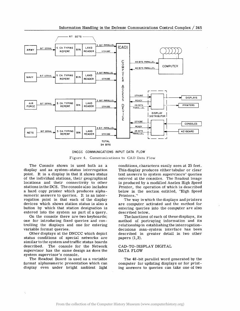
These teletype formatted messages are precoded at the point of origin as a message which is both readable by man and suitable for entrance directly into the Philco 2000 Computer. Each of the data gathering centers relays the teletype messages in a bit-serial teletype code to an associated tape repeater RT set at the DNCCC. At the DNCCC, the start and stop pulses are stripped and a 5,level edge-printed chadless tape is produced in each RT set. This tape is fed into a tape storage bin from whence it goes to a 200 words-per-minute tape reader. All four of these RT-set tape readers can read the last character punched. All four tape readers are read in unison, each producing a parallel 6-bit character (5-bit code plus a strobe). The information from 4 simultaneously read tapes is combined to form a series of 24-bit parallel words. Any tape having no data on it causes the associated portion of the word sent to the CAD to be represented by zeros. Each 24 bit word is put into the CAD for transfer into the computer. A block diagram showing the path of this communications input for DCS status data is shown in Figure 4.
DISPLAY DATA OUTPUT
The display data presented to the system supervisors is in two forms:
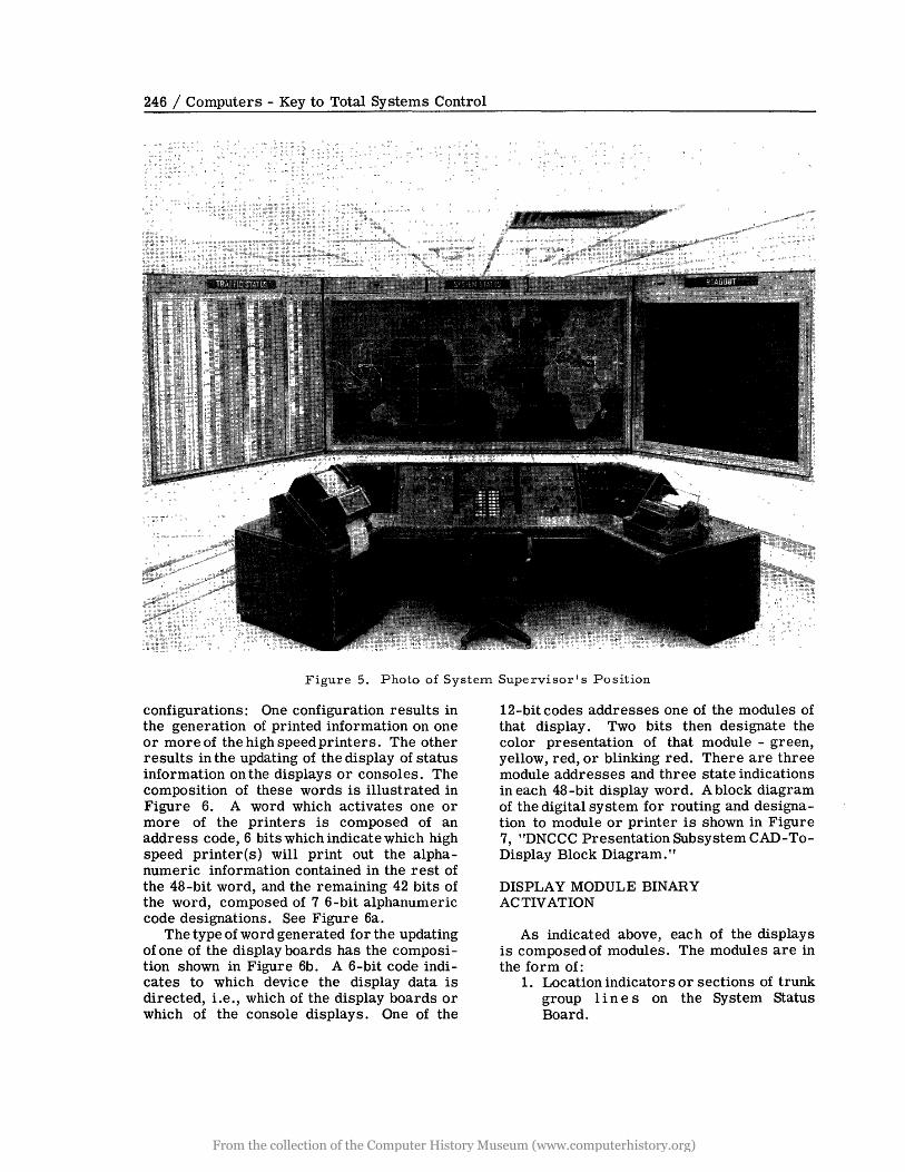
1. Status display, as illustrated in Figure 5 by the Sy stem Status Board in the center, the Traffic Status Board on the left, and the Supervisor's Console in the foreground.
2. Printed clear text or tabular information, available at the high speed printer on the left of the console, or projected white with a black background on the Readout Board.
All of the Status Board and Console Display Modules have computer controlled multicolor capability. Alarm conditions are easily recognized by their blinking red indication. The system continues to display a newly deteriorated condition by causing the associated indicators to continue in the blinking state until the supervisor acknowledges their presence.
The System Display Board, 8 by 15 feet, is a geographical presentation of the world upon which are super-imposed the locations of all the DCS relay stations. Between these locations, their inter-connections are shown by lines representing trunk groups. Each half of these lines has a different color capability, thus showing the condition of the communications link in both directions. The appearance of a white halo around any location rectangle indicates that there is a station at that location which has a serious traffic backlog. Reference for detailed information must then be made to the Traffic Status Board, shown to the left in Figure 5. The representation on this board conveys to the system supervisor information as to the communications capabilities of the various stations comprising the DCS and the effectiveness of the communications between these locations.
The Traffic Status Board is arranged to correspond to the relative geographical locationfor all DCS reporting stations and shows their traffic backlog condition for both High and Low precedence messages. This display board has the capability of, upon interrogation at the console, displaying the traffic status condition from any station to any of the stations directly connected with/it. Each of these modules has computer cOl,ltrolled multicolored capability to indicate status condition.
From the collection of the Computer History Museum (www.computerhistory.org)
Information Handling in the Defense Communications Control Complex / 245
;-RT SETS~
I ARMY I BIT SERIAL 5 CH TYPING LAXD BIN
REPERF. READER
I NAVY I BIT SERIAL 5 CH. TYPING
BIN LAXD
r REPERF. READER
I AIR I 5 CH. TYPING LAXD BIT SERIAL
FORCE I REPERF. BIN READER
I NETS 1 BIT SERIAL 5 CH. TYPING LAXD BIN
REPERF READER
5 BIT PARALLEL
STROBE
5 BIT ~RALLEL
STROBE
5 BIT PARALLEL
STROBE
5 BIT PARALLEL
STR OBE
TOTAL
24 BITS
(CAD)
C 0 M P U T E R
A C C E s S
0 E V I C E
))))) 1 ,I
48 BITS PARALLEL ,.
48 BITS PARALLEL COMPUTER
r--. STROBE I- I ~I I I DISPLAYS READY I I -
1-"0 r 1 48 BITS 1 PRINTERS
I I PARALLEL
I DISPLAY I DISTRIBUTOR
1 I _ STROBE r I 1.. I CONSOLES READY I I
_ 24 BITS 1 1 KEYBOARD I 1 -PARALLEL 1 L __ ..J
DNCCC COMMUNICATIONS INPUT DATA FLOW
Figure 4. Communications to CAD Data Flow
The Console shown is used both as a display and as system-status interrogation point. It is a display in that it shows status of the individual stations, their geographical locations and their connectivity to other stations in the DCS. The console also includes a hard copy printer which produces alphanumeric answers to queries. It is an interrogation point in that each of the display devices which shows station status is also a button by which that station designation is entered into the system as part of a query.
On the console there are two keyboards; one for introducing fixed queries and controlling the displays and one for entering variable format queries.
Other displays at the DNCCC which depict status conditions of special networks are similar to the system and traffic status boards described. The console for the Network supervisor has the same design as does the system supervisor's console.
The Readout Board is used as a variable format alphanumeric presentation which can display even under bright ambient light
conditions, characters easily seen at 25 feet. This display produces either tabular or clear text answers to system supervisors' queries entered at the consoles. The Readout image is produc ed by a modified Anelex High Speed Printer, the operation of which is described below in the section entitled, "High Speed Printers."
The way in which the displays and printers are computer activated and the method for entering queries into the computer are also described below.
The functions of each of these displays, its method of portraying information and its relationship in establishing the interrogationdecisions man-system interface has been described in greater detail in two other papers (1,2).
CAD-TO-DISPLA Y DIGITAL DATA FLOW
The 48 -bit parallel word generated by the computer for updating displays or for printing answers to queries can take one of two
From the collection of the Computer History Museum (www.computerhistory.org)
246 / Computers - Key to Total Systems Control
<' ":, ~ , <' ",
~~~,,~~w
Figure 5. Photo of System Supervisor I s Position
configurations: One configuration results in the generation of printed information on one or more of the high speedprinters. The other results in the updating of the display of status information on the displays or consoles. The composition of these words is illustrated in Figure 6. A word which activates one or more of the printers is composed of an address code, 6 bits which indicate which high speed printer(s) will print out the alphanumeric information contained in the rest of the 48-bit word, and the remaining 42 bits of the word, composed of 7 6-bit alphanumeric code designations. See Figure 6a.
The type of word generated for the updating of one of the display boards has the composition shown in Figure 6b. A 6-bit code indicates to which device the display data is directed, Le., which of the display boards or which of the console displays. One of the
12-bit codes addresses one of the modules of that display. Two bits then designate the color presentation of that module - green, yellow, red, or blinking red. There are three module addresses and three state indications in each 48 -bit display word. A block diagram of the digital system for routing and designation to module or printer is shown in Figure 7, "DNCCC Presentation Subsystem CAD-ToDisplay Block Diagram."
DISPLAY MODULE BINARY ACTIVATION
As indicated above, each of the displays is composed of modules. The modules are in the form of:
1. Location indicators or sections of trunk group lin e s on the System Status Board.
From the collection of the Computer History Museum (www.computerhistory.org)

Information Handling in the Defense Communications Control Complex / 247
r 48 BITS -----------------.. 1 I 6 I 6 6 6 6 6 6 6 I
~-----------------------_ _----------------------i~/ V To Printer(s)
Seven Alphanumeric Characters to Selected Printer(s)
(a) PRINTER MODE
6 I 12 121 12 121 12 121 \. / \.
Y V / "- V
.I
To Address of Address of Address of
Display Display Module Display Module Display Module
(Board or Console)
Module Module Module
Display Display Display
State State State
(b) DIS P LAY MOD E
Figure 6. CAD to Display Words
2. High or low precedence backlog indicators on the Traffic Status Board.
3. Stations or communication links on the Special Network Boards or,
4. Station indicators on the consoles. Each of these modules has four states of operation. The module indicates status by color, either green, yellow, red or blinking red. An operational check is automatically performed, in that, absence of color indicates a malfunction. Each of these modules has a continuous operating life of over 100 years, and also has its own four - state memory. This module memory will retain stored information even in the event of power failure. Thus, once a module is addressed and has stored two - digital bits which determine the module's display state, it need not be addressed again
until that module is to change its display state. The addressing of a display module which has its own storage capability relieves the computer and routing circuitry of the burden of repetitious excitation which some types of displays need to maintain a continuous non-flickering presentation.
HIGH SPEED PRINTER ACTIVATION
The DNCCC incorporates 4 high-speed Anelexprinters. One 120-character per line, 900 lines per minute printer is driven directly by the computer. Three 72-character per line printers are used in the Presentation Subsystem to furnish information to the system supervisors. One is mounted on each of the two consoles, and one, a modified printer,
From the collection of the Computer History Museum (www.computerhistory.org)

248 / Computers - Key to Total Systems Control
AUXILIARY 15 llNESI GATES 8 DRIVERS f4----
I """ I TRAFFIC ~ GATES I -] CONSOLE
STATUS HOl D (10 llNESI
GATES 8 DRIVERS ~ J PRINTER
BOARD NO I
SELECT
~ 2 liNES GATES 8 DRIVERS L6
i ,nwo", I ~ ~ GATES CONSOLE
SYSTEM -I PRINTER N02
STATUS L--BOARD GATES 8 DRIVERS ~
f- Y GATES: -I READOUT I ~I PRINTER
NO 3
NETWORK
STATUS
BOARD GATES 8 DRIVERS ~
I f-~ FUNCTION I
~ BITS 2-IB
TO 2-19 GATES r
STATUS GATES I-
"iN N 0 0 .. .. .. BITS 2-6 TO 2-47 POLAR TTY "iN ~
r
GATE RELAY SET
<II <II .. .. iii iii
I 48 BIT REGISTER I
i <II
0:
~ DATA (48 liNES I J DATA LINE 1 <II Z
1 RCRS 1 c .. 0: ..
~ CAD
STROBE LINE RCR 1 J
PROGRAM I ] CONTROL ] READY lEVEL LINE I
DR
ONCCC PRESENTATION SUBSYSTEM
Figure 7. DNCCC Presentation Subsystem CAD to Display Block Diagram
is part of the Readout Projection system. Each of these printers has a rotating drum which has rows of metal type parallel with the axis of rotation. Each row contains 72-type representations of one character. Rows of the different alphanumeric characters are distributed around the periphery of the drum. This drum is so mounted that each row of type passes adjacent to a length of inked ribbon, on the other side of which is a length of paper. Situated behind the paper is a row of 72 magnetically-activated hammers. These are so positioned that when activated, they cause the paper to push the ribbon against a type face in one of the columns of the continuously rotating drum. The striking of a hammer is so rapid that a clear image of the letter appears on the paper. To get a line of printed information, it is thus necessary that each of the 72 hammers strike as the proper letter passes in front of it.
Rotating with the drum is a digitally encoded wheel. On this wheel there is a binary representation of each character on the drum. Associated with each hammer is
a 6-bit storage register and a comparison circuit. When the digital representation of a character in a printer register is identical with that on the encoded wheel, the hammer is activated, causing the character to be printed on the paper in the position associated with that register.
Printer control-functions also appear as 6-bit codes. For economy and because of human limitation, the printers of the presentation subsystem are not operated at 900 lines per minute. The character recognition circuitry is time-shared, decreasing its speed and thereby reducing the cost and complexity.
To print a line on one of the printers, words from the CAD, directed by the display distributor, are read to the printers as a serial stream of 6-bit parallel characters. The printers commutate the characters and put them in a proper comparison registers so that the appropriate character is printed in any given line position.
The Readout Board incorporates a projection system which rapidly produces, by
From the collection of the Computer History Museum (www.computerhistory.org)

Information Handling in the Defense Communications Control Complex / 249
non-chemical means, a transparency of clear text or tabular alphanumeric information. This transparency is produced by a modified Anelex printer at printer operating speeds, similar to the ones described above. This transparency is used in proj ecting an easily readable image on a 7 x 7 ft. screen. The image may be read at 25 feet in a room having an ambient lighting of 25-foot lamberts, standard office illumination.
Details of this display system are described in greater detail in another paper (2).
QUERY DATA INPUT
Queries can be asked by the system or net supervisor by activation of buttons on the appropriate console. Answers to queries appear either on the printers, or, in some cases, on the displays, as described below.
CONSOLE TO CAD DIGITAL DATA FLOW
Each of the station display indicators on the System Supervisor console is a pushbutton,
, 24 BITS I
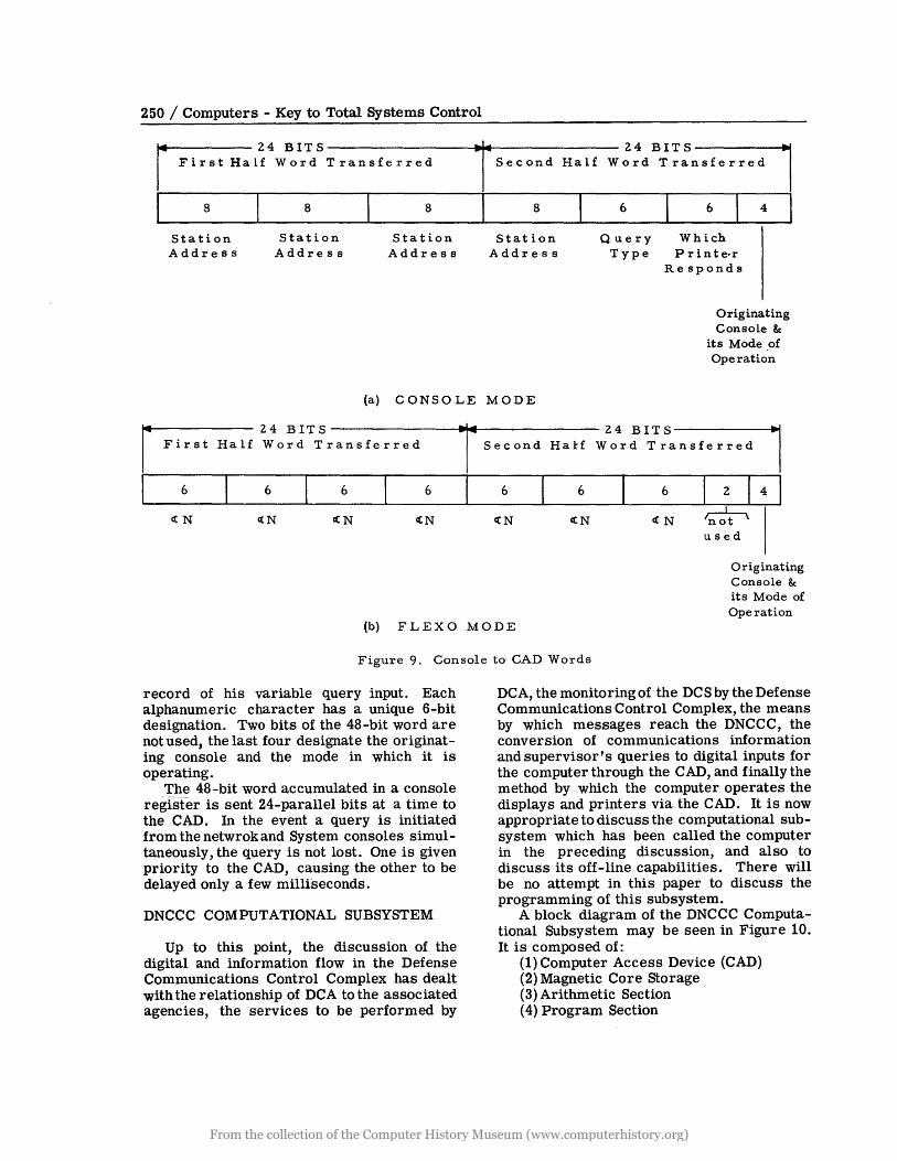
which, when depressed, is connected to a decimal-to-binary converter as is shown in Figure 8. DepreSSing a pushbutton results in a unique 8 -bit word being placed in 8 of the positions of the 48-bit register associated with that console when the console is operating in the console mode. As shown in Figure 9a, 4 pushbuttons can be depressed, each contributing 8-bits to the 48-bit word which will be sent to the CAD. Thefollowing 6-bits of the word indicate the type of qq.ery being asked, the next 6-bits dictate on which printer(s) the answer to the query will be printed. The last 4-bits of the 48-bit word specify the originating console and in which mode it is operating, either console or flexowriter. If the system supervisor wishes to put in a variable format query, he must put the console in the Flexo mode. The depression of the' jlexowriter keys results in the storage, in the 48-bit register of the console, of 7 alphanumeric characters as shown in Figure 9b.
The symbols are simultaneou'sly printed on the flexowriter so the supervisor has a
CAD
READY
GATING
24 BITS t A~ S' J + 24 BITS
T R 0
I 24 BITS B , 24 BITS J E
48- BIT CONTROL 48-BIT ... PROGRAMMER REG. - - REG. S INTERLOCK
1 ~ f ~
I
DECIMAL TO DECIMAL TO DECIMAL TO DECIMAL TO BINARY CONY. BINARY CONY. BINARY CONY. BINARY CONY.
J,l l J~ A~
SYSTEM SYSTEM NETWGRK NETWORK CONSOLE FLEXOWRITER CONSOLE FLEXOWRITER
Figure 8. DNCCC Pre sentation Subsystem - Console to CAD Block Diagram
From the collection of the Computer History Museum (www.computerhistory.org)
250 / Computers - Key to Total Systems Control
~24BITS I First Half Word Transferred
I 8 I 8 I 8
Station Address
Station Address
Station Address
Tsecond Half
I 8
Station Address
24BITS~ Word Transferred I
Query Type
Which P r inte·r
Responds
Originating Console &
its Mode .of Operation
(a) CONSOLE MODE
r 24 BIT S T . Fir st Ha lf Word Transferred Second
I 6 6 6 6 I 6
CCN c(N cCN cCN ctN
Hal-f
I 6
CCN
24 BITS Word Transferred l
6
c(N
2 I 4 I ~ used
Originating Console & its Mode of Operation
(b) FLEXO MODE
Figure 9. Console to CAD Words
record of his variable query input. Each alphanumeric character has a unique 6-bit designation. Two bits of the 48-bit word are not used, the last four designate the originating console and the mode in which it is operating.
The 48 -bit word accumulated in a console register is sent 24-parallel bits at a time to the CAD. In the event a query is initiated from the netwrok and System consoles simultaneously, the query is not lost. One is given priority to the CAD, causing the other to be delayed only a few milliseconds.
DNCCC COMPUTATIONAL SUBSYSTEM
Up to this point, the discussion of the digital and information flow in the Defense Communications Control Complex has dealt with the relationship of DCA to the associated agencies, the services to be performed by
DCA, the monitoring of the DCS by the Defense Communications Control Complex, the means by which messages reach the DNCCC, the conversion of communications information and supervisor's queries to digital inputs for the computer through the CAD, and finally the method by which the computer operates the displays and printers via the CAD. It is now appropriate to discuss the computational subsystem which has been called the computer in the preceding discussion, and also to discuss its off-line capabilities. There will be no attempt in this paper to discuss the programming of this subsystem.
A block diagram of the DNCCC Computational Subsystem may be seen in Figure 10. It is composed of:
(1) Computer Access Device (CAD) (2) Magnetic Core Storage (3) Arithmetic Section (4) Program Section
From the collection of the Computer History Museum (www.computerhistory.org)

Information Handling in the Defense Communications Control Complex / 251
qOMMUNICATIONS
CENTRAL COMPUTER
I ARITH. I
I SECTIJN
I I
UNIVERSAL BUFFER
CONTROLI~ER (UBC)
~----~~MAGNETIC INPUT OUTPUT
ROCESSJR (lOP)
OFF-LINE ON-~INE
TAPE2 DISPLAYS CAD
QUERYS
24 Bits CORE Parallel STOaAGE
8219 WORDS
PROGRAM ~Q.Tl~
7 TAPE UNITS
Figure 10. DNCCC Computational Subsystem
(5) Input-Output Processor (6) Universal Buffer Controller (7) Punch Card System (8) High Speed Printer (9) Nine magnetic tape units Items (2), (3) and (4) as listed make up the
Central Computer.
The CAD arranges all input and output data in 48-bitparallel words, this word length being one which can conveniently be handled by the Processing Subsystem.
2. Magnetic Core Storage
The Magnetic Core Storage is capable of storing 8,192 words, each one 48 bits in length. This unit contains in part a data register and an address register. The magnetic core storage is shared by central computer, the input-output processor and the CAD. This sharing interweaves the memoryaccess periods of the various units so that none must wait more than a few microseconds to use the memory. Therefore, with memory sharing, the program runs almost continuously, without interruption by input -output operations.
3. Arithmetic Section
Data is processed in the arithmetic section by arithmetic comparison, shifting, and extracting operations. These arithmetical operations are performed in the adder network. This network is extremely fast since it contains no storage registers and operates in parallel on all 48 bits of a word.
4. Program Section
The central computer processes the stored data in accordance with the program instructions. The program section interprets and executes the instructions.
5. Input-Output Processor
The input-output processor is the interconnecting and control link between the central computer and 16 input-output channels. Each of the channels couples either' a magnetic tape unit or a Universal Buffer -Controller to the central Computer. Standard data-transfer rate over a channel is 90,000 alphanumeric characters per second. By multiplexing, the input-output processor can automatically connect any two of the channels to the central computer for input or output.
From the collection of the Computer History Museum (www.computerhistory.org)

252 / Computers - Key to Total Systems Control
6. The Universal Buffer-Controller
The Universal Buffer-Controller acts as a buffering device between any two inputoutput units. It permits off-line conversion between any two media.
7. The Punchcard System
The Punchcard System can read 80-column punched cards at a rate of 2000 cards per minute. Cards can be punched at a rate of 100 cards per minute. The card image mode facilitates handling of binary information and packs 12 bits, or two characters in each column. Plug-board editing provides format control.
8. High Speed Printer
The High Speed Printer and its printer controller operate in conjunction with the Universal Buffer-Controller. The printer prints 900 lines of one hundred and twenty characters each line per minute. By skip feeding, non -printed areas are passed at ten times the normal printing rate.
9. Tape Units
The Magnetic tape units record data in fixe~~ block form to provide efficient operation, checking, and tape reading in forward and backward directions. This bi -directional tape readingis especially valuable for saving time in sorting operations. The read-write speedis 90,000 alphanumeric characters per second. The size of a standard block is 128 words, recorded in 512 frames. Each frame contains 12 data bits, two parity bits and two timing bits. As an additional control, a 513th frame adds to each of the fourteen horizontal channels an even parity bit for longitudinal parity checking of the block.
The above listed components are interconnected as dictated by the Programming, to perform the functions needed by the DNCCC Computational Subsystem. A few examples of the internal computational equipment connections required for performing some of these functions are illustrated in Figure 11 and given below. Mode 1. Initial load - taking programs
which have been manually punched into cards and entering these programs into the appropriate computer facility storage areas.
Mode 2. Load to correct - used to enter changes or corrections into already utilized storage areas.
Mode 3. In-line path I - normal operating condition for the system.
Mode 4. In-line path II - operating condition in the event of a detected error in the input data.
Mode 5. Query path I - a console request for stored information to be presented on display subsystem equipment.
Mode 6. Query path II - a console request for stored information to be printed using the c.;omputer facility high speed printer.
Mode 7. Tape Print - the transfer of infor.mation from magnetic tape storage to hard copy via the computer high speed printer. Used primarily to print out Error Tape data and Record and Report Tape data.
The asynchronous nature of this Philco 2000 Computational Subsystem enables very rapid up-dating of the data base, manipulation and direction of data flow, retrieval of stored information and presentation of answers to queries. A well rounded under standing of the general operation of the DNCCC should include a knowledge of t~e manipulation of the data base as well as the control center method of deriving and disseminating information.
DATA BASE
One element critical to effective DNCCC operation is the Data Base. This is a representation of the DCS which is stored within the computational subsystem. The data base includes fixed structural data describing DC S, and the more dynamic allocation of facilities to users. It also includes information needed for current operations, predicted future operations and planned operations.
CIRCUIT DIRECTORY
The circuit directory consists of that data which remains comparatively stable (e.g., trunk, channel, and circuit numbers, type of facility and service, owner, etc .). This directory is used to facilitate the control of the DeS; to analyze trunk group, trunk, channel, and circuit usage; to provide detailed information to the managers of the DeS that will assist them in making efficient use of all
From the collection of the Computer History Museum (www.computerhistory.org)

Information Handling in the Defense Communications Control Complex / 253
OPERATING MODE I - LOAD SYSTEM
OPERATING MODE :3 - IN-LINE PATH I
OPERATING MODE 4-IN-LINE PATH n
OPERATI NG MODE 5 - QUERY PATH I: COMPUTER FACILITY ----------r------.
I I I I I __________ ...1
OPERATI NG MODE 6 - QUERY PATH n COMPUTER FACILITY r::- - - - - - - - - - - - - - - - - - - - --,
I I I , I I ____ _ ___________ -.J
OPERATING MODE 7- TAPE PRINT
Figure 11. Functional ArrangeITlent of COITlputational SubsysteITl COITlponents
From the collection of the Computer History Museum (www.computerhistory.org)

254 / Computers - Key to Total Systems Control
of the communication facilities of the DC S, particularly during emergencies; and to furnish data on trunk groups, trunks, channels and circuits that may be used in the future development of the DCS.
Circuit directory information is filed on punched cards which are modified, added, or removed as changes occur. A card similar to the one shown in Figure 12 is prepared for each communication link within the DCS.
STATUS REPORTS
Reports sent to the DNCCC by the data gathering centers of the DCS are called Status Reports. They are prepared in a format which enables the DNCCC Computational Subsystem to process them automatically as they are received. These contain information on outages, backlogs, routing, users, and traffic.
ERROR CORRECTION AND PURGING
Each information line of a status report is automatically checked for range and
I I I III
legality by the Computational Subsystem. If a status report does not pass all of the tests stipulated by the error detection program the erroneous portions of the report are forwarded to an operator at the Model 28ASR console through program selection of a magnetic tape output which is printed out on the high speed printer off-line through the Universal Buffer Controller. The error correction operator will make corrections and re-enter the data through the DNCCC communications input via his keyboard.
DNCCC COMPUTATIONAL SUBSYSTEM TAPES
The physical counterpart of the Data Base and the programming instructions in the DNCCC Computational Subsystem is found on its magnetic tapes. A better understanding of the manipulation and storage of the Data Base information within the DNCCC may be derived by reviewing the types and functions of the computational tapes used in this system.
I
122!222222222222222
3333333333333333333
444144444144 444444444444444444414444444444444444444 4444444444444444444 o. 01
555555555555555555555555555555555555555555555555555555555555 5555555555555555555
6&&666&&81&&&&66666666&666 &61661666666166666166666666666666 666666666&6666&1666
~I
il 11111111111111111111777117711117117777 77777777777777171771711111777771111111171
8888888888888888888888888888888188 •• 8.8888888888.88.88 •• 8.88.88.88.8 ••• 8.8 •• 1 ••• I
Figure 12. Circuit Directory Card
From the collection of the Computer History Museum (www.computerhistory.org)
Information Handling in the Defense Communications Control Complex / 255
MASTER TAPE
This tape contains all the DNCCC programs and subroutines, initial system parameters, and some utility-type programs ..
STATION DIRECTORY TAPE
The station directory tape includes all data on stations, trunk groups, trunks, channels and allocated circuits within the DCS.
JOURNAL STATUS TAPE
This tape contains, in chronological tabular form, all the latest information on the status of each component of the DCS.
JOURNAL STATUS PRIME TAPE
This tape contains a rearranged set of Journal Status data which has been sorted according to station by the sort and merge program.
RELIABILITY LIBRARY TAPE
This tape contains, for each trunk and channel, a reliability figure on a monthly running basis. It also contains all reasons for outages by percentage for that outage.
ERROR/OUTPUT TAPE
This tape is used to store the output of detected error contained in the incoming status reports. It is read out onto the computational subsystem high speed printer on demand.
SCRATCH TAPE
The Executive and Start-over routines use this tape for such purposes as saving core, Journal Status backup, and intermediate working storage. Other routines which need storage in excess of that available to them in core also use this tape.
SIMULATION TAPE
For introducing controlled inputs during training periods, a simulation facility can
construct tape images similar to the inputs normally read from the CAD.
OFF-LINE CAPABILITY OF THE DNCCC COMPUTATIONAL SUBSYSTEM
This paper has emphasized the on-line capability of the DNCCC. It should not be inferred that the computational subsystem is used more than a small portion of the time to carry out this on-line function. The design of the Defense National Communications Control Center has given it inherent processing and display storage. For all the displays have their own internal storage either in display modules or in the form of hard copy, thus eliminating the need for repetitive use of the computer to maintain displayed information. Tapes and core are the computational subsystems storage media. This storage capacity allows the computational subsystem to devote most of its processing time to the performance of computation required for offline management of the Defense Communications System.
SUMMARY
The purpose of this paper is to give the reader an understanding of the method of handling information "on-line" in the Defense Communications Agency's Defense Communications Control Complex.
The control system described here is only the initial phase of the implementation of the Defense Communications Agency Control Center Complex (DCA CCC) a series of communications control centers throughout the free world.
CONCLUSION
On 29 September 1960, the Defense Communications Agency selected Philco Corporation as prime contractor to set up the Defense National Communications Control Center discussed above. Normally such a program would take more than a year to complete. In less tahn 22 weeks, however, Philco designed, developed, manufactured and installed the complex equipments which make up this Center.
From the collection of the Computer History Museum (www.computerhistory.org)

256 / Computers - Key to Total Systems Control
REFERENCES
1. "Defense Communications Control Complex," T. J. Heckelman, presented at 7th National Communications S y m p 0 s i u m, Utica, N. Y.
2. "Coupling Man, the Decision Maker, to the Defense Communications Control Complex," R. H. Lazinski, presented at 7th National Communications Sy mpo s i um, Utica, N. Y.
From the collection of the Computer History Museum (www.computerhistory.org)