Embed Size (px)
Citation preview
OPERATING RANGE:
K4124B
L124A
SERIES DESCRIPTION
124A, 124AE, 4124A, 4124AE, 324A, 4324A:The Universal Product Line has the broadest range of sealing options of all pumps built by Viking. The stuffing box on all sizes accepts packing, numerous component single mechanical seals, or a wide variety of cartridge seals.
The Universal Product Line is Viking Pump’s most versatile line of internal gear pumps due to the availability of many design and material options.
SERIES
NOMINAL FLOW
MAXIMUM PRESSURE
TEMPERATURE RANGE
VISCOSITY RANGE
GPM m3h PSI Bar °F °C SSU cSt124A/AE* 8 - 500 1.8 - 114 200 14 −60 to +450 −50 to +230 28 to 2,000,000 0.1 to 440,000
4124A/AE* 8 - 500 1.8 - 114 200 14 −60 to +450 −50 to +230 28 to 2,000,000 0.1 to 440,000
4124B 8 - 500 1.8 - 114 200 14 −60 to +450 −50 to +230 28 to 15,000 0.1 to 3,300
324A 600 - 1,600 136 - 364 200 14 −60 to +450 −50 to +230 28 to 2,000,000 0.1 to 440,000
4324A 600 - 1,600 136 - 364 200 14 −60 to +450 −50 to +230 28 to 2,000,000 0.1 to 440,000
* AE available in sizes L, LQ, LL only.
4124B:The 4124B series heavy duty internal gear pumps have Behind the Rotor dynamic shaft seals. By locating the mechanical seal immediately behind the rotor, this prevents the shaft and bracket bushing from coming into contact with the liquid.
RELATED PRODUCTSCast Iron, Jacketed Pumps: Catalog Section 1402
Cast Iron, Mag Drive Pumps: Catalog Section 1403
Steel Externals, Non-Jacketed Pumps: Catalog Section 1301
Stainless Steel, Non-Jacketed Pumps: Catalog Section 1701
TABLE OF CONTENTSFeatures & Benefits ...................................................................2Port Location Options ................................................................2Model Number Key ....................................................................3Standard Materials of Construction ...........................................3Cutaway View & Pump Features (124A/AE, 4124A/AE, 324A, 4324A) ...4Cutaway View & Pump Features (4124B) ....................................5Special Materials & Options Selection Guidelines ....................6Specifications – G through L Sizes ............................................7Specifications – LQ through RS Sizes .......................................8Optional Casings ........................................................................9Dimensions – G through Q & M Sizes .....................................10Dimensions – G through Q & M Sizes (Continued) ......................11Dimensions – QS Size .............................................................12Dimensions – N, R & RS Sizes – Jacketed Bracket (324A, 4324A) ...................................................13Dimensions – Stuffing Box Seal Chamber (Except 4124B) ...........14NPSH Required .......................................................................15
• A Unit of IDEX Corporation • Cedar Falls, IA ©2017
Section 1401Page 1401.1Issue BSERIES 124A, 124AE, 4124A, 4124AE, 4124B, 324A, 4324A
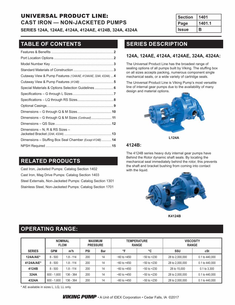
UNIVERSAL PRODUCT LINE: CAST IRON — NON-JACKETED PUMPS
FEATURES & BENEFITS• Positive Displacement Internal Gear pumping principle
handles a broad range of viscosities with constant flow rate
• Axial rotor thrust is controlled by double row ball bearing or tapered roller bearings; a bushing provides a secondary point of radial shaft support
• Rotatable bearing housing provides easy rotor end clearance adjustment for viscosity or to compensate wear
• Numerous material options are available for bushings, idler pins, shafts, rotors, idlers and elastomers
• Gear and pump geometry has been optimized based on more than 100 years of experience
• Footed cast iron bracket provides rigid mounting to help maintain alignment, which extends seal and bearing life
• Can use direct drive, gear reducer or gearmotor drive, or belt-drive
• Pressure relief valve standard on all except RS size pumps; less valve / plain head option available
124A, 124AE, 4124A, 4124AE, 324A, 4324A:• Series designed with an enlarged bearing housing.
Used in conjunction with a spacer coupling permits easy cartridge seal installation and removal in place without removing the head and rotor/shaft.
• Seal options include packing, single component seals, cartridge lip seals and cartridge single and double mechanical seals. Various seal flush plans are available.
Viking Universal Product Line pumps carry a three year limited warranty. See catalog section 000 for details.
PORT LOCATION OPTIONS90° port options:
Opposite port options:
NOTE: See page 1401.9 for a complete list of casing options by size.
• A Unit of IDEX Corporation • Cedar Falls, IA ©2017
Section 1401Page 1401.2Issue B SERIES 124A, 124AE, 4124A, 4124AE, 4124B, 324A, 4324A
UNIVERSAL PRODUCT LINE: CAST IRON — NON-JACKETED PUMPS
STANDARD MATERIALS OF CONSTRUCTION
Component Standard MaterialCasing Cast Iron, ASTM A48, Class 35B
Head Cast Iron, ASTM A48, Class 35B
Bracket Cast Iron, ASTM A48, Class 35B
IdlerStandard ① Cast Iron, ASTM A48, Class 35B
Steel Fitted ①② Cast Iron, ASTM A48, Class 35B
RotorStandard ③ Cast Iron, ASTM A48, Class 35B
Steel Fitted ④ Steel, ASTM A148, Grade 80-40
Shaft ⑤ Steel, ASTM A108, Grade 1045
Idler Pin Hardened Steel, ASTM A108, Grade 1045
Idler Bushing(4124A, 4124AE, 4324A, 4124B) Carbon Graphite
(124A, 124AE, 324A) Bronze, ASTM B584 (B505), Alloy C93700
Bracket Bushing (no product contact on 4124B series)(4124A, 4124AE, 4324A) Carbon Graphite
(124A, 124AE, 324A, 4124B) Bronze, ASTM B584 (B505), Alloy C93700
Pressure Relief Valve ⑥ Cast Iron, ASTM A48, Class 35B
Standard Packing (124A, 124AE, 324A) Braided PTFE
Standard Mechanical Seal (4124A, 4124AE, 4124B, 4324A) Carbon vs. Silicon Carbide Faces, Viton™ Elastomers
Optional Abrasive Liquid Seal (4124B) Silicon Carbide vs. Silicon Carbide Faces, Viton™ Elastomers
① G, H and HL sizes have a powdered metal idler: Powdered Metal MPIF 35, FC-0208-50 (G) , Powdered Metal MPIF 35, FC-0208-45 (H, HL)② Q and QS sizes have a hardened steel idler when pump is steel fitted: ASTM A148 Grade 80-40.③ AK, KK, LS, QS, N and RS sizes have ductile iron rotor: ASTM A536 Grade 60-40-18.④ Material specification for HL steel rotor is AISI 8620, LS steel rotor is ASTM A148 80-50.⑤ L, LQ, LL and LS sizes, including “A”, “AE”, and “B” models, are high strength steel ASTM A434 Type 4140 Grade BC or equivalent.⑥ RS relief valve not available. Contact factory for options.
Viton™ is a trademark of The Chemours Company FC, LLC.
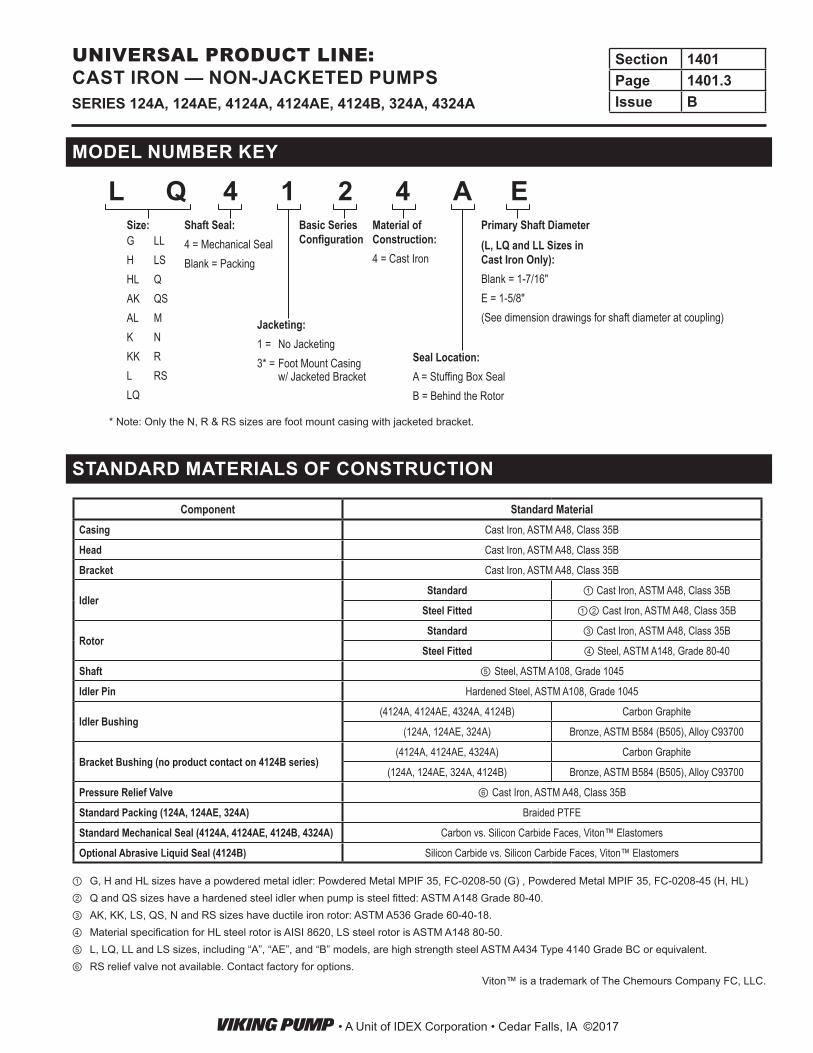
MODEL NUMBER KEY
L Q 4 1 2 4 A E
Jacketing:1 = No Jacketing3* = Foot Mount Casing
w/ Jacketed Bracket
Shaft Seal:4 = Mechanical SealBlank = Packing
Material of Construction:4 = Cast Iron
Size:
Seal Location:A = Stuffing Box SealB = Behind the Rotor
Primary Shaft Diameter(L, LQ and LL Sizes in Cast Iron Only):Blank = 1-7/16"E = 1-5/8"(See dimension drawings for shaft diameter at coupling)
Basic Series ConfigurationG
HHLAKALKKKLLQ
LLLSQQSMNRRS
* Note: Only the N, R & RS sizes are foot mount casing with jacketed bracket.
• A Unit of IDEX Corporation • Cedar Falls, IA ©2017
Section 1401Page 1401.3Issue BSERIES 124A, 124AE, 4124A, 4124AE, 4124B, 324A, 4324A
UNIVERSAL PRODUCT LINE: CAST IRON — NON-JACKETED PUMPS
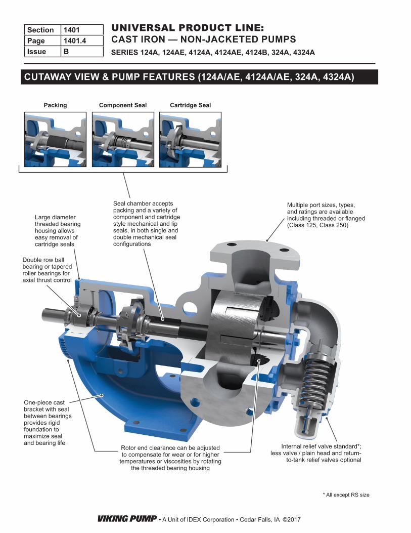
Multiple port sizes, types, and ratings are available including threaded or flanged (Class 125, Class 250)
Rotor end clearance can be adjusted to compensate for wear or for higher
temperatures or viscosities by rotating the threaded bearing housing
One-piece cast bracket with seal between bearings provides rigid foundation to maximize seal and bearing life
* All except RS size
Double row ball bearing or tapered roller bearings for axial thrust control
Internal relief valve standard*; less valve / plain head and return-
to-tank relief valves optional
Large diameter threaded bearing housing allows easy removal of cartridge seals
Seal chamber accepts packing and a variety of component and cartridge style mechanical and lip seals, in both single and double mechanical seal configurations
Cartridge SealComponent SealPacking
CUTAWAY VIEW & PUMP FEATURES (124A/AE, 4124A/AE, 324A, 4324A)
• A Unit of IDEX Corporation • Cedar Falls, IA ©2017
Section 1401Page 1401.4Issue B SERIES 124A, 124AE, 4124A, 4124AE, 4124B, 324A, 4324A
UNIVERSAL PRODUCT LINE: CAST IRON — NON-JACKETED PUMPS
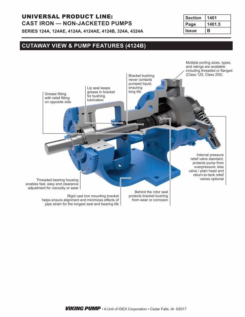
CUTAWAY VIEW & PUMP FEATURES (4124B)
Threaded bearing housing enables fast, easy end clearance
adjustment for viscosity or wear
Rigid cast iron mounting bracket helps ensure alignment and minimizes effects of
pipe strain for the longest seal and bearing life
Lip seal keeps grease in bracket for bushing lubrication
Grease fitting with relief fitting on opposite side
Bracket bushing never contacts pumped liquid, ensuring long life
Internal pressure relief valve standard,
protects pump from overpressure; less
valve / plain head and return-to-tank relief
valves optional
Behind the rotor seal protects bracket bushing
from wear or corrosion
Multiple porting sizes, types, and ratings are available including threaded or flanged (Class 125, Class 250)
• A Unit of IDEX Corporation • Cedar Falls, IA ©2017
Section 1401Page 1401.5Issue BSERIES 124A, 124AE, 4124A, 4124AE, 4124B, 324A, 4324A
UNIVERSAL PRODUCT LINE: CAST IRON — NON-JACKETED PUMPS
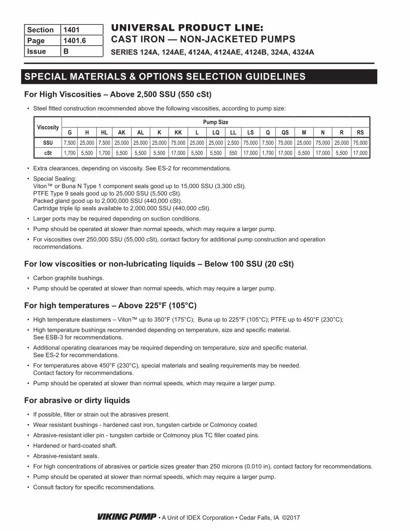
SPECIAL MATERIALS & OPTIONS SELECTION GUIDELINES
For High Viscosities – Above 2,500 SSU (550 cSt)• Steel fitted construction recommended above the following viscosities, according to pump size:
ViscosityPump Size
G H HL AK AL K KK L LQ LL LS Q QS M N R RSSSU 7,500 25,000 7,500 25,000 25,000 25,000 75,000 25,000 25,000 2,500 75,000 7,500 75,000 25,000 75,000 25,000 75,000
cSt 1,700 5,500 1,700 5,500 5,500 5,500 17,000 5,500 5,500 550 17,000 1,700 17,000 5,500 17,000 5,500 17,000
• Extra clearances, depending on viscosity. See ES-2 for recommendations.
• Special Sealing: Viton™ or Buna N Type 1 component seals good up to 15,000 SSU (3,300 cSt). PTFE Type 9 seals good up to 25,000 SSU (5,500 cSt). Packed gland good up to 2,000,000 SSU (440,000 cSt). Cartridge triple lip seals available to 2,000,000 SSU (440,000 cSt).
• Larger ports may be required depending on suction conditions.
• Pump should be operated at slower than normal speeds, which may require a larger pump.
• For viscosities over 250,000 SSU (55,000 cSt), contact factory for additional pump construction and operation recommendations.
For low viscosities or non-lubricating liquids – Below 100 SSU (20 cSt)• Carbon graphite bushings.
• Pump should be operated at slower than normal speeds, which may require a larger pump.
For high temperatures – Above 225°F (105°C)• High temperature elastomers – Viton™ up to 350°F (175°C); Buna up to 225°F (105°C); PTFE up to 450°F (230°C);
• High temperature bushings recommended depending on temperature, size and specific material. See ESB-3 for recommendations.
• Additional operating clearances may be required depending on temperature, size and specific material. See ES-2 for recommendations.
• For temperatures above 450°F (230°C), special materials and sealing requirements may be needed. Contact factory for recommendations.
• Pump should be operated at slower than normal speeds, which may require a larger pump.
For abrasive or dirty liquids• If possible, filter or strain out the abrasives present.
• Wear resistant bushings - hardened cast iron, tungsten carbide or Colmonoy coated.
• Abrasive-resistant idler pin - tungsten carbide or Colmonoy plus TC filler coated pins.
• Hardened or hard-coated shaft.
• Abrasive-resistant seals.
• For high concentrations of abrasives or particle sizes greater than 250 microns (0.010 in), contact factory for recommendations.
• Pump should be operated at slower than normal speeds, which may require a larger pump.
• Consult factory for specific recommendations.
• A Unit of IDEX Corporation • Cedar Falls, IA ©2017
Section 1401Page 1401.6Issue B SERIES 124A, 124AE, 4124A, 4124AE, 4124B, 324A, 4324A
UNIVERSAL PRODUCT LINE: CAST IRON — NON-JACKETED PUMPS
Model Number
③Standard
NPT Port Size
Nominal Pump Rating (100 SSU & below)
④ Maximum Hydrostatic
Pressure
① Maximum Discharge
Pressure
② Maximum Recommended Temperature for Standard Pump
Approx. Shipping Weight with Valve
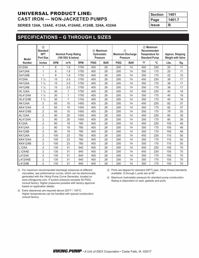
Inches GPM m3/h RPM PSIG BAR PSIG BAR °F °C Lbs. Kg.G124A 1 8 1.8 1750 400 28 200 14 450 230 25 11G4124A 1 8 1.8 1750 400 28 200 14 350 175 25 11G4124B 1 8 1.8 1750 400 28 200 14 350 175 22 10H124A 1 ½ 15 3.5 1750 400 28 200 14 450 230 38 17H4124A 1 ½ 15 3.5 1750 400 28 200 14 350 175 38 17H4124B 1 ½ 15 3.5 1750 400 28 200 14 350 175 38 17HL124A 1 ½ 30 7 1750 400 28 200 14 450 230 40 18HL4124A 1 ½ 30 7 1750 400 28 200 14 350 175 40 18HL4124B 1 ½ 30 7 1750 400 28 200 14 350 175 40 18AK124A 2 65 15 1450 400 28 200 14 450 230 82 37AK4124A 2 65 15 1450 400 28 200 14 350 175 82 37AK4124B 2 65 15 1450 400 28 200 14 350 175 78 35AL124A 2 90 20 1450 400 28 200 14 450 230 85 39AL4124A 2 90 20 1450 400 28 200 14 350 175 85 39K124A 2 80 18 780 400 28 200 14 450 230 105 48K4124A 2 80 18 780 400 28 200 14 350 175 105 48K4124B 2 80 18 780 400 28 200 14 350 175 105 48KK124A 2 100 23 780 400 28 200 14 450 230 110 50KK4124A 2 100 23 780 400 28 200 14 350 175 110 50KK4124B 2 100 23 780 400 28 200 14 350 175 110 50L124A 2 135 31 640 400 28 200 14 450 230 155 70L124AE 2 135 31 640 400 28 200 14 450 230 155 70L4124A 2 135 31 640 400 28 200 14 350 175 155 70L4124AE 2 135 31 640 400 28 200 14 350 175 155 70L4124B 2 135 31 640 400 28 200 14 350 175 155 70
SPECIFICATIONS – G THROUGH L SIZES
① For maximum recommended discharge pressures at different viscosities, see performance curves, which can be electronically generated with the Viking Pump Curve Generator, located on www.vikingpump.com. If suction pressure exceeds 50 PSIG, consult factory. Higher pressures possible with factory approval based on application details.
② Extra clearances are required above 225°F / 105°C. Higher temperatures can be handled with special construction, consult factory.
③ Ports are tapped for standard (NPT) pipe. Other thread standards available. G through L ports are at 90°.
④ Maximum hydrostatic pressure for standard pump construction. Rating is dependent on seal, gaskets and ports.
• A Unit of IDEX Corporation • Cedar Falls, IA ©2017
Section 1401Page 1401.7Issue BSERIES 124A, 124AE, 4124A, 4124AE, 4124B, 324A, 4324A
UNIVERSAL PRODUCT LINE: CAST IRON — NON-JACKETED PUMPS
Model Number
③StandardPort Size
Nominal Pump Rating (100 SSU & below)
④ Maximum Hydrostatic
Pressure
① Maximum Discharge Pressure for 100 SSU liquid
at rated speed
② Maximum Recommended Temperature for Standard Pump
Approx. Shipping Weight with Valve
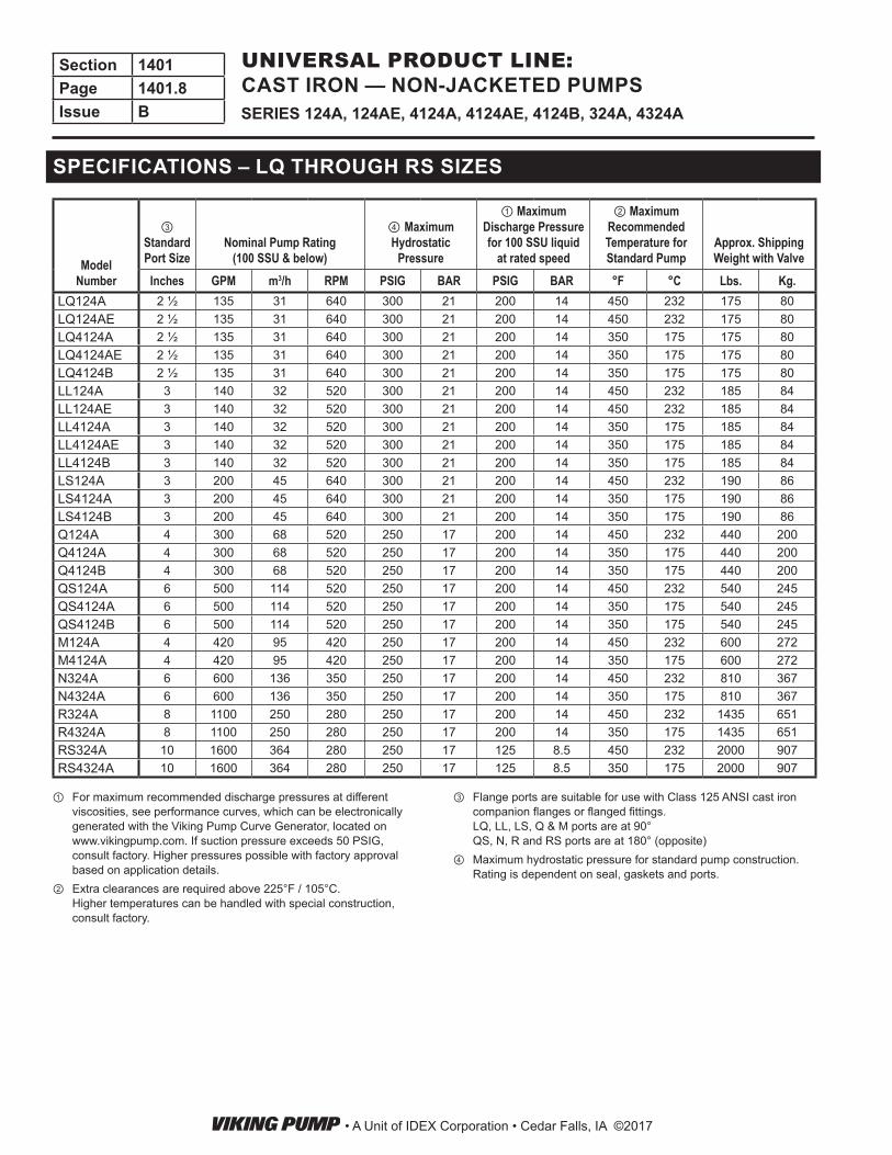
Inches GPM m3/h RPM PSIG BAR PSIG BAR °F °C Lbs. Kg.LQ124A 2 ½ 135 31 640 300 21 200 14 450 232 175 80LQ124AE 2 ½ 135 31 640 300 21 200 14 450 232 175 80LQ4124A 2 ½ 135 31 640 300 21 200 14 350 175 175 80LQ4124AE 2 ½ 135 31 640 300 21 200 14 350 175 175 80LQ4124B 2 ½ 135 31 640 300 21 200 14 350 175 175 80LL124A 3 140 32 520 300 21 200 14 450 232 185 84LL124AE 3 140 32 520 300 21 200 14 450 232 185 84LL4124A 3 140 32 520 300 21 200 14 350 175 185 84LL4124AE 3 140 32 520 300 21 200 14 350 175 185 84LL4124B 3 140 32 520 300 21 200 14 350 175 185 84LS124A 3 200 45 640 300 21 200 14 450 232 190 86LS4124A 3 200 45 640 300 21 200 14 350 175 190 86LS4124B 3 200 45 640 300 21 200 14 350 175 190 86Q124A 4 300 68 520 250 17 200 14 450 232 440 200Q4124A 4 300 68 520 250 17 200 14 350 175 440 200Q4124B 4 300 68 520 250 17 200 14 350 175 440 200QS124A 6 500 114 520 250 17 200 14 450 232 540 245QS4124A 6 500 114 520 250 17 200 14 350 175 540 245QS4124B 6 500 114 520 250 17 200 14 350 175 540 245M124A 4 420 95 420 250 17 200 14 450 232 600 272M4124A 4 420 95 420 250 17 200 14 350 175 600 272N324A 6 600 136 350 250 17 200 14 450 232 810 367N4324A 6 600 136 350 250 17 200 14 350 175 810 367R324A 8 1100 250 280 250 17 200 14 450 232 1435 651R4324A 8 1100 250 280 250 17 200 14 350 175 1435 651RS324A 10 1600 364 280 250 17 125 8.5 450 232 2000 907RS4324A 10 1600 364 280 250 17 125 8.5 350 175 2000 907
SPECIFICATIONS – LQ THROUGH RS SIZES
① For maximum recommended discharge pressures at different viscosities, see performance curves, which can be electronically generated with the Viking Pump Curve Generator, located on www.vikingpump.com. If suction pressure exceeds 50 PSIG, consult factory. Higher pressures possible with factory approval based on application details.
② Extra clearances are required above 225°F / 105°C. Higher temperatures can be handled with special construction, consult factory.
③ Flange ports are suitable for use with Class 125 ANSI cast iron companion flanges or flanged fittings. LQ, LL, LS, Q & M ports are at 90° QS, N, R and RS ports are at 180° (opposite)
④ Maximum hydrostatic pressure for standard pump construction. Rating is dependent on seal, gaskets and ports.
• A Unit of IDEX Corporation • Cedar Falls, IA ©2017
Section 1401Page 1401.8Issue B SERIES 124A, 124AE, 4124A, 4124AE, 4124B, 324A, 4324A
UNIVERSAL PRODUCT LINE: CAST IRON — NON-JACKETED PUMPS
Size
Standard Casings
Optional CasingsPorts
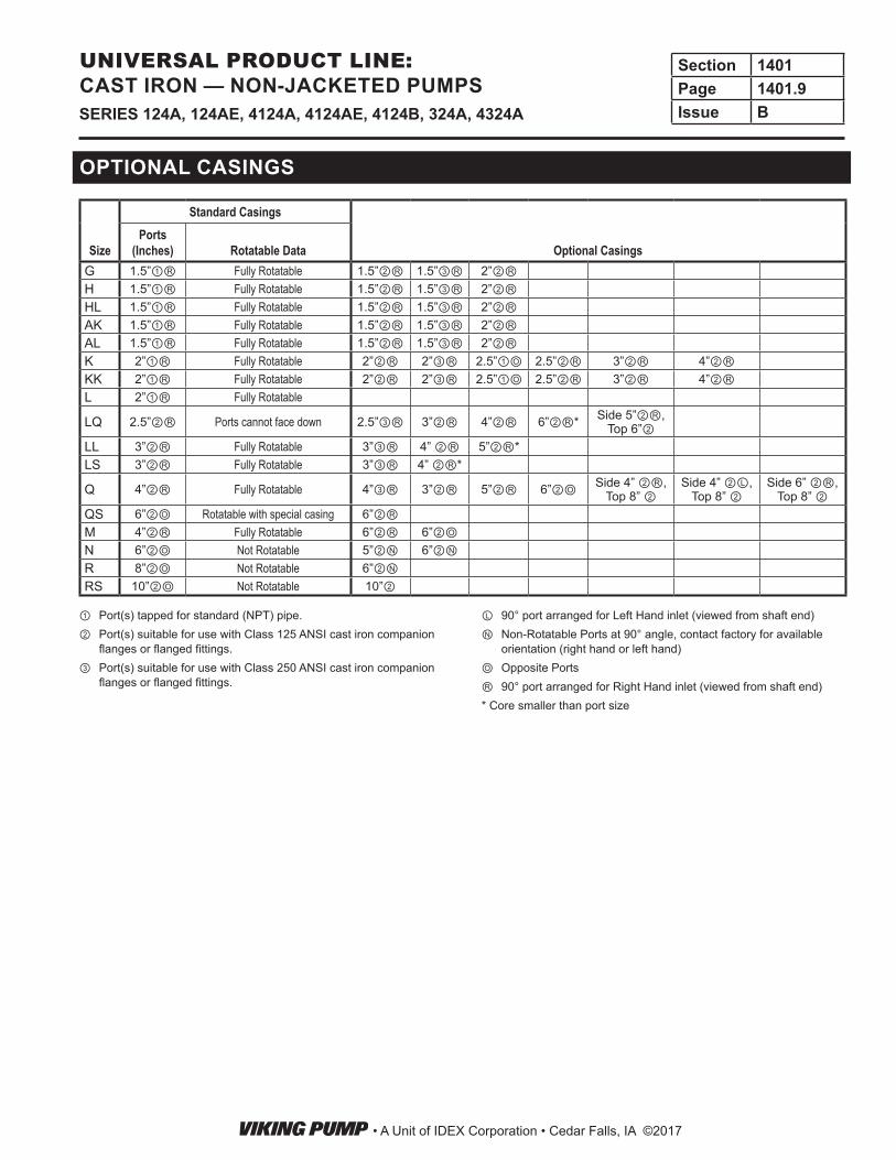
(Inches) Rotatable DataG 1.5”①Ⓡ Fully Rotatable 1.5”②Ⓡ 1.5”③Ⓡ 2”②ⓇH 1.5”①Ⓡ Fully Rotatable 1.5”②Ⓡ 1.5”③Ⓡ 2”②ⓇHL 1.5”①Ⓡ Fully Rotatable 1.5”②Ⓡ 1.5”③Ⓡ 2”②ⓇAK 1.5”①Ⓡ Fully Rotatable 1.5”②Ⓡ 1.5”③Ⓡ 2”②ⓇAL 1.5”①Ⓡ Fully Rotatable 1.5”②Ⓡ 1.5”③Ⓡ 2”②ⓇK 2”①Ⓡ Fully Rotatable 2”②Ⓡ 2”③Ⓡ 2.5”①Ⓞ 2.5”②Ⓡ 3”②Ⓡ 4”②ⓇKK 2”①Ⓡ Fully Rotatable 2”②Ⓡ 2”③Ⓡ 2.5”①Ⓞ 2.5”②Ⓡ 3”②Ⓡ 4”②ⓇL 2”①Ⓡ Fully Rotatable
LQ 2.5”②Ⓡ Ports cannot face down 2.5”③Ⓡ 3”②Ⓡ 4”②Ⓡ 6”②Ⓡ* Side 5”②Ⓡ, Top 6”②
LL 3”②Ⓡ Fully Rotatable 3”③Ⓡ 4” ②Ⓡ 5”②Ⓡ*LS 3”②Ⓡ Fully Rotatable 3”③Ⓡ 4” ②Ⓡ*
Q 4”②Ⓡ Fully Rotatable 4”③Ⓡ 3”②Ⓡ 5”②Ⓡ 6”②Ⓞ Side 4” ②Ⓡ, Top 8” ②
Side 4” ②Ⓛ, Top 8” ②
Side 6” ②Ⓡ, Top 8” ②
QS 6”②Ⓞ Rotatable with special casing 6”②ⓇM 4”②Ⓡ Fully Rotatable 6”②Ⓡ 6”②ⓄN 6”②Ⓞ Not Rotatable 5”②Ⓝ 6”②ⓃR 8”②Ⓞ Not Rotatable 6”②ⓃRS 10”②Ⓞ Not Rotatable 10”②
OPTIONAL CASINGS
① Port(s) tapped for standard (NPT) pipe. ② Port(s) suitable for use with Class 125 ANSI cast iron companion
flanges or flanged fittings. ③ Port(s) suitable for use with Class 250 ANSI cast iron companion
flanges or flanged fittings.
Ⓛ 90° port arranged for Left Hand inlet (viewed from shaft end)Ⓝ Non-Rotatable Ports at 90° angle, contact factory for available
orientation (right hand or left hand)Ⓞ Opposite PortsⓇ 90° port arranged for Right Hand inlet (viewed from shaft end)* Core smaller than port size
• A Unit of IDEX Corporation • Cedar Falls, IA ©2017
Section 1401Page 1401.9Issue BSERIES 124A, 124AE, 4124A, 4124AE, 4124B, 324A, 4324A
UNIVERSAL PRODUCT LINE: CAST IRON — NON-JACKETED PUMPS
NRT
K
S W
PFHM L
U
V D
C
OE E
G
J
B
B A
Model NumberA
(in)B C D E F G H J K L M
Packed Mechanical Seal
G124A G4124A G4124B ① 1 in 2.50 3.66 2.75 1.62 1.31 4.00 2.38 0.34 0.57 1.21 4.87
mm 64 93 70 41 33 102 60 9 14 31 124
H124AHL124A
H4124AH4124BHL4124AHL4124B
① 1.5in 3.00 4.75 3.50 2.75 2.25 6.75 3.50 0.47 0.99 3.38 5.19
mm 76 121 89 70 57 171 89 12 25 86 132
AK124AAL124A
AK4124AAL4124AAK4124B
① 2in 4.50 6.75 5.25 2.88 2.00 6.75 4.03 0.41 1.67 2.82 8.84
mm 114 171 133 73 51 171 102 10 42 72 225
K124AKK124A
K4124AK4124BKK4124AKK4124B
① 2in 5.12 8.00 5.50 4.00 2.75 9.25 4.00 0.53 1.42 3.00 9.38
mm 130 203 140 102 70 235 102 13 36 76 238
L124A/AE L4124A/AEL4124B ① 2 in 6.50 10.25 7.00 4.38 4.00 10.00 5.38 0.53 1.42 ④ 3.38 9.12
mm 165 260 178 111 102 254 137 13 36 ④ 86 232
LQ124A/AE LQ4124A/AELQ4124B ② 2.5 in 7.19 10.25 7.00 4.38 4.00 10.00 5.38 0.53 1.42 ④ 3.38 9.12
mm 183 260 178 111 102 254 137 13 36 ④ 86 232
LL124A/AE LL4124A/AELL4124B ② 3 in 7.19 10.25 7.00 4.38 4.00 10.00 5.38 0.53 1.42 ④ 3.38 9.12
mm 183 260 178 111 102 254 137 13 36 ④ 86 232
LS124A LS4124ALS4124B ② 3 in 7.19 10.25 7.00 4.38 4.00 10.00 5.38 0.53 2.55 4.75 9.12
mm 183 260 178 111 102 254 137 13 65 121 232
Q124A Q4124AQ4124B ② 4 in 8.25 14.00 8.75 4.12 4.00 10.00 6.00 0.69 3.58 6.62 11.12
mm 210 356 222 105 102 254 152 18 91 168 282
M124A M4124A ② 4 in 9.50 17.35 10.00 5.00 6.00 12.00 8.53 0.69 3.50 7.75 8.10mm 241 441 254 127 152 305 217 18 89 197 206
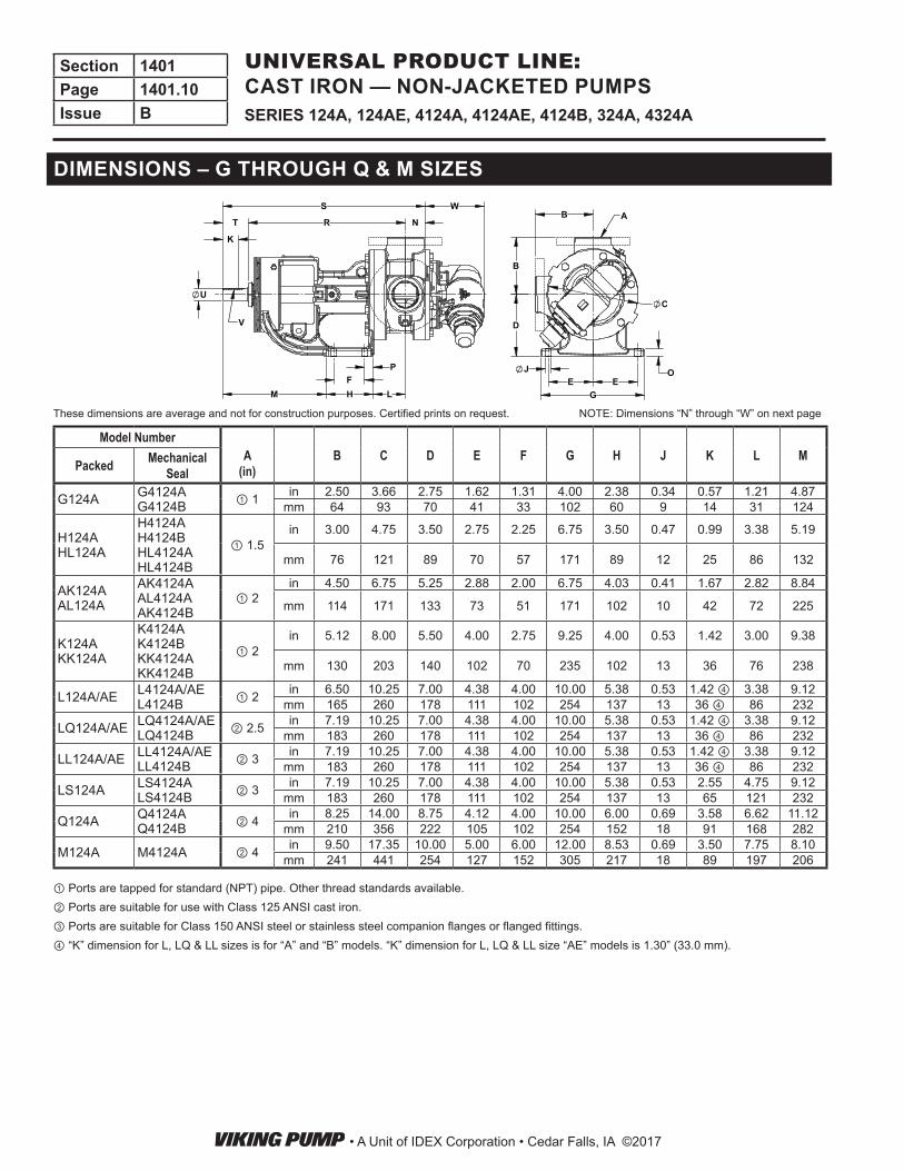
① Ports are tapped for standard (NPT) pipe. Other thread standards available.② Ports are suitable for use with Class 125 ANSI cast iron.③ Ports are suitable for Class 150 ANSI steel or stainless steel companion flanges or flanged fittings.④ “K” dimension for L, LQ & LL sizes is for “A” and “B” models. “K” dimension for L, LQ & LL size “AE” models is 1.30” (33.0 mm).
DIMENSIONS – G THROUGH Q & M SIZES
NOTE: Dimensions “N” through “W” on next pageThese dimensions are average and not for construction purposes. Certified prints on request.
• A Unit of IDEX Corporation • Cedar Falls, IA ©2017
Section 1401Page 1401.10Issue B SERIES 124A, 124AE, 4124A, 4124AE, 4124B, 324A, 4324A
UNIVERSAL PRODUCT LINE: CAST IRON — NON-JACKETED PUMPS
NRT
K
S W
PFHM L
U
V D
C
OE E
G
J
B
B A
Model NumberN O P R S T U
(in)V
(in) WPacked Mechanical
Seal
G124A G4124A G4124B
in 1.09 0.31 0.63 7.40 9.55 1.06 0.50 .12 x .06 2.71mm 28 8 16 188 143 27 69
H124AHL124A
H4124AH4124BHL4124AHL4124B
in 1.19 0.56 0.62 10.44 13.25 1.620.75 .19 x .09
2.85
mm 30 14 16 265 337 41 72
AK124AAL124A
AK4124AAL4124AAK4124B
in 2.00 0.44 1.00 13.19 17.69 2.501.00 .25 x .12
4.83
mm 51 11 25 335 449 64 123
K124AKK124A
K4124AK4124BKK4124AKK4124B
in 1.75 0.62 0.62 14.12 18.12 2.251.12 .25 x .12
5.25
mm 44 16 16 359 460 57 133
L124A L4124A in 1.75 0.62 0.62 15.62 19.62 2.25 1.12 .25 x .12 5.43mm 44 16 16 397 498 57 138
L124AE L4124AEL4124B
in 1.75 0.62 0.62 15.62 19.62 2.35 1.44 .38 x .19 5.43mm 44 16 16 397 498 60 138
LQ124A LQ4124A in 1.75 0.62 0.62 15.62 19.62 2.25 1.12 .25 x .12 5.43mm 44 16 16 397 498 57 138
LQ124AE LQ4124AELQ4124B
in 1.75 0.62 0.62 15.62 19.62 2.35 1.44 .38 x .19 5.43mm 44 16 16 397 498 60 138
LL124A LL4124A in 2.25 0.62 0.62 15.62 20.12 2.25 1.12 .25 x .12 5.43mm 57 16 16 397 511 57 138
LL124AE LL4124AELL4124B
in 2.25 0.62 0.62 15.62 20.12 2.35 1.44 .38 x .19 5.43mm 57 16 16 397 511 60 138
LS124A LS4124ALS4124B
in 2.44 0.62 0.62 15.75 21.69 3.50 1.44 .38 x .19 5.43mm 62 16 16 400 551 89 138
Q124A Q4124AQ4124B
in 3.00 0.8 1.00 19.25 26.75 4.50 1.94 .50 x .25 8.25mm 76 20 25 489 679 114 210
M124A M4124A in 4.00 1.00 1.52 20.13 28.38 4.25 1.94 .50 x .25 8.61mm 102 25 39 511 721 108 219
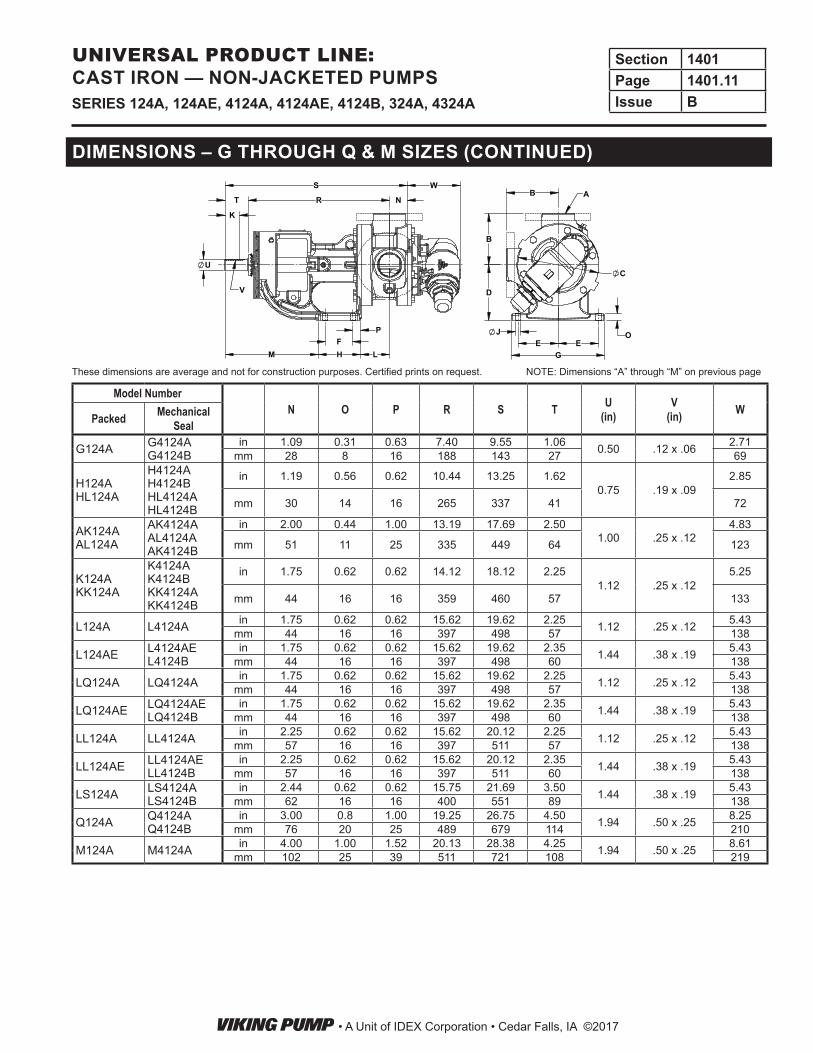
DIMENSIONS – G THROUGH Q & M SIZES (CONTINUED)
NOTE: Dimensions “A” through “M” on previous pageThese dimensions are average and not for construction purposes. Certified prints on request.
• A Unit of IDEX Corporation • Cedar Falls, IA ©2017
Section 1401Page 1401.11Issue BSERIES 124A, 124AE, 4124A, 4124AE, 4124B, 324A, 4324A
UNIVERSAL PRODUCT LINE: CAST IRON — NON-JACKETED PUMPS
4.00102
1.0025
6.00152
11.13283
7.12181
1.94
4.37111
4.50114
19.75502
4.00102
8.29211
28.25718
FLANGE*
.50 X .25KEYWAY
9.00229
9.00229
2X 3.0076
8.75222
.8121
4.12105
4.12105
10.00254
4X .69
.8822
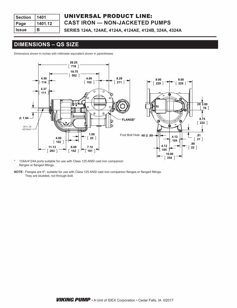
DIMENSIONS – QS SIZE
Foot Bolt Hole
* 124A/4124A ports suitable for use with Class 125 ANSI cast iron companion flanges or flanged fittings.
Dimensions shown in inches with millimeter equivalent shown in parentheses
NOTE: Flanges are 6", suitable for use with Class 125 ANSI cast iron companion flanges or flanged fittings. They are studded, not through-bolt.
• A Unit of IDEX Corporation • Cedar Falls, IA ©2017
Section 1401Page 1401.12Issue B SERIES 124A, 124AE, 4124A, 4124AE, 4124B, 324A, 4324A
UNIVERSAL PRODUCT LINE: CAST IRON — NON-JACKETED PUMPS
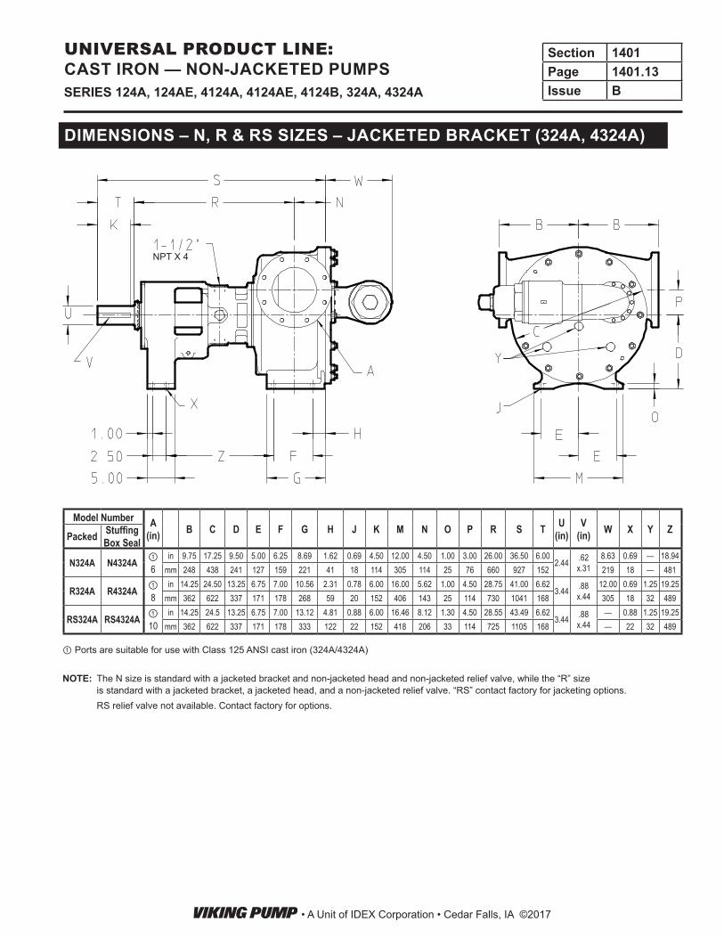
DIMENSIONS – N, R & RS SIZES – JACKETED BRACKET (324A, 4324A)
Model Number A(in) B C D E F G H J K M N O P R S T U
(in)V
(in) W X Y ZPacked Stuffing Box Seal
N324A N4324A ①6
in 9.75 17.25 9.50 5.00 6.25 8.69 1.62 0.69 4.50 12.00 4.50 1.00 3.00 26.00 36.50 6.002.44 .62
x.318.63 0.69 — 18.94
mm 248 438 241 127 159 221 41 18 114 305 114 25 76 660 927 152 219 18 — 481
R324A R4324A ①8
in 14.25 24.50 13.25 6.75 7.00 10.56 2.31 0.78 6.00 16.00 5.62 1.00 4.50 28.75 41.00 6.623.44 .88
x.4412.00 0.69 1.25 19.25
mm 362 622 337 171 178 268 59 20 152 406 143 25 114 730 1041 168 305 18 32 489
RS324A RS4324A ①10
in 14.25 24.5 13.25 6.75 7.00 13.12 4.81 0.88 6.00 16.46 8.12 1.30 4.50 28.55 43.49 6.623.44 .88
x.44— 0.88 1.25 19.25
mm 362 622 337 171 178 333 122 22 152 418 206 33 114 725 1105 168 — 22 32 489
① Ports are suitable for use with Class 125 ANSI cast iron (324A/4324A)
NOTE: The N size is standard with a jacketed bracket and non-jacketed head and non-jacketed relief valve, while the “R” size is standard with a jacketed bracket, a jacketed head, and a non-jacketed relief valve. “RS” contact factory for jacketing options.
RS relief valve not available. Contact factory for options.
NPT X 4
• A Unit of IDEX Corporation • Cedar Falls, IA ©2017
Section 1401Page 1401.13Issue BSERIES 124A, 124AE, 4124A, 4124AE, 4124B, 324A, 4324A
UNIVERSAL PRODUCT LINE: CAST IRON — NON-JACKETED PUMPS
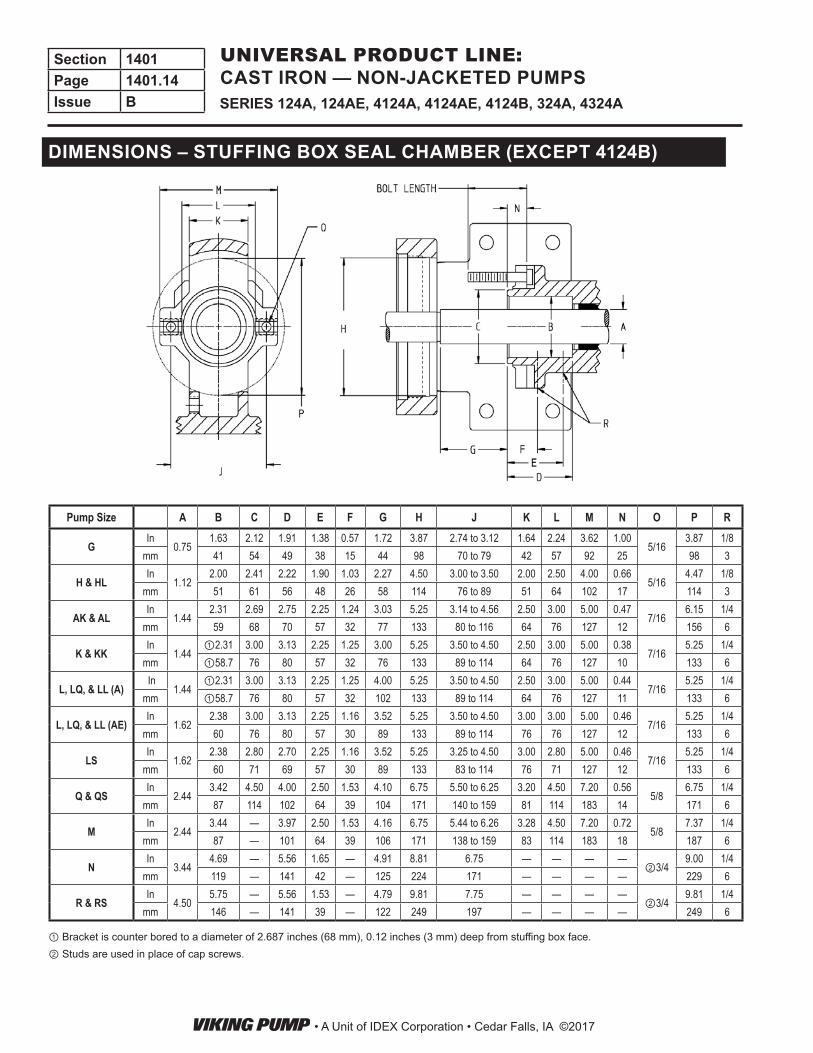
DIMENSIONS – STUFFING BOX SEAL CHAMBER (EXCEPT 4124B)
Pump Size A B C D E F G H J K L M N O P R
GIn
0.751.63 2.12 1.91 1.38 0.57 1.72 3.87 2.74 to 3.12 1.64 2.24 3.62 1.00
5/163.87 1/8
mm 41 54 49 38 15 44 98 70 to 79 42 57 92 25 98 3
H & HLIn
1.122.00 2.41 2.22 1.90 1.03 2.27 4.50 3.00 to 3.50 2.00 2.50 4.00 0.66
5/164.47 1/8
mm 51 61 56 48 26 58 114 76 to 89 51 64 102 17 114 3
AK & ALIn
1.442.31 2.69 2.75 2.25 1.24 3.03 5.25 3.14 to 4.56 2.50 3.00 5.00 0.47
7/166.15 1/4
mm 59 68 70 57 32 77 133 80 to 116 64 76 127 12 156 6
K & KKIn
1.44①2.31 3.00 3.13 2.25 1.25 3.00 5.25 3.50 to 4.50 2.50 3.00 5.00 0.38
7/165.25 1/4
mm ①58.7 76 80 57 32 76 133 89 to 114 64 76 127 10 133 6
L, LQ, & LL (A) In
1.44①2.31 3.00 3.13 2.25 1.25 4.00 5.25 3.50 to 4.50 2.50 3.00 5.00 0.44
7/165.25 1/4
mm ①58.7 76 80 57 32 102 133 89 to 114 64 76 127 11 133 6
L, LQ, & LL (AE)In
1.622.38 3.00 3.13 2.25 1.16 3.52 5.25 3.50 to 4.50 3.00 3.00 5.00 0.46
7/165.25 1/4
mm 60 76 80 57 30 89 133 89 to 114 76 76 127 12 133 6
LSIn
1.622.38 2.80 2.70 2.25 1.16 3.52 5.25 3.25 to 4.50 3.00 2.80 5.00 0.46
7/165.25 1/4
mm 60 71 69 57 30 89 133 83 to 114 76 71 127 12 133 6
Q & QSIn
2.443.42 4.50 4.00 2.50 1.53 4.10 6.75 5.50 to 6.25 3.20 4.50 7.20 0.56
5/86.75 1/4
mm 87 114 102 64 39 104 171 140 to 159 81 114 183 14 171 6
MIn
2.443.44 — 3.97 2.50 1.53 4.16 6.75 5.44 to 6.26 3.28 4.50 7.20 0.72
5/87.37 1/4
mm 87 — 101 64 39 106 171 138 to 159 83 114 183 18 187 6
NIn
3.444.69 — 5.56 1.65 — 4.91 8.81 6.75 — — — —
②3/49.00 1/4
mm 119 — 141 42 — 125 224 171 — — — — 229 6
R & RSIn
4.505.75 — 5.56 1.53 — 4.79 9.81 7.75 — — — —
②3/49.81 1/4
mm 146 — 141 39 — 122 249 197 — — — — 249 6
① Bracket is counter bored to a diameter of 2.687 inches (68 mm), 0.12 inches (3 mm) deep from stuffing box face.② Studs are used in place of cap screws.
• A Unit of IDEX Corporation • Cedar Falls, IA ©2017
Section 1401Page 1401.14Issue B SERIES 124A, 124AE, 4124A, 4124AE, 4124B, 324A, 4324A
UNIVERSAL PRODUCT LINE: CAST IRON — NON-JACKETED PUMPS
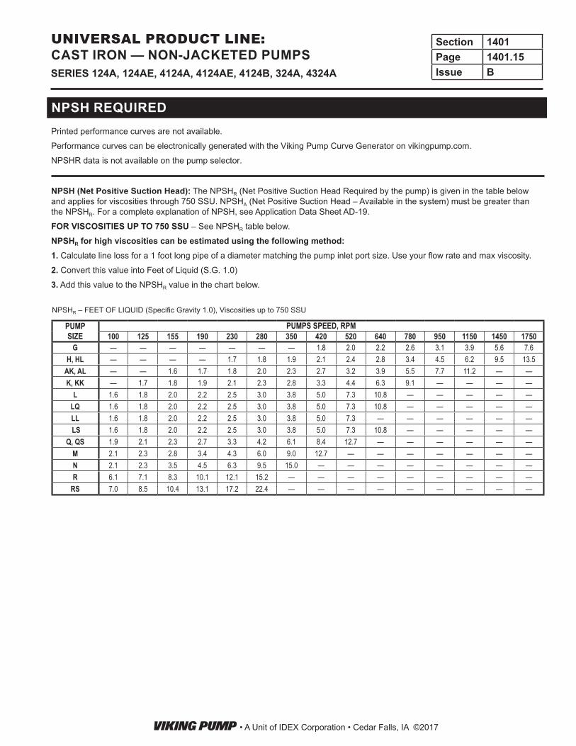
NPSH (Net Positive Suction Head): The NPSHR (Net Positive Suction Head Required by the pump) is given in the table below and applies for viscosities through 750 SSU. NPSHA (Net Positive Suction Head – Available in the system) must be greater than the NPSHR. For a complete explanation of NPSH, see Application Data Sheet AD-19.
FOR VISCOSITIES UP TO 750 SSU – See NPSHR table below.
NPSHR for high viscosities can be estimated using the following method:1. Calculate line loss for a 1 foot long pipe of a diameter matching the pump inlet port size. Use your flow rate and max viscosity.
2. Convert this value into Feet of Liquid (S.G. 1.0)
3. Add this value to the NPSHR value in the chart below.
NPSH REQUIRED
NPSHR – FEET OF LIQUID (Specific Gravity 1.0), Viscosities up to 750 SSU
PUMP SIZE
PUMPS SPEED, RPM100 125 155 190 230 280 350 420 520 640 780 950 1150 1450 1750
G — — — — — — — 1.8 2.0 2.2 2.6 3.1 3.9 5.6 7.6H, HL — — — — 1.7 1.8 1.9 2.1 2.4 2.8 3.4 4.5 6.2 9.5 13.5
AK, AL — — 1.6 1.7 1.8 2.0 2.3 2.7 3.2 3.9 5.5 7.7 11.2 — —K, KK — 1.7 1.8 1.9 2.1 2.3 2.8 3.3 4.4 6.3 9.1 — — — —
L 1.6 1.8 2.0 2.2 2.5 3.0 3.8 5.0 7.3 10.8 — — — — —LQ 1.6 1.8 2.0 2.2 2.5 3.0 3.8 5.0 7.3 10.8 — — — — —LL 1.6 1.8 2.0 2.2 2.5 3.0 3.8 5.0 7.3 — — — — — — LS 1.6 1.8 2.0 2.2 2.5 3.0 3.8 5.0 7.3 10.8 — — — — —
Q, QS 1.9 2.1 2.3 2.7 3.3 4.2 6.1 8.4 12.7 — — — — — —M 2.1 2.3 2.8 3.4 4.3 6.0 9.0 12.7 — — — — — — —N 2.1 2.3 3.5 4.5 6.3 9.5 15.0 — — — — — — — —R 6.1 7.1 8.3 10.1 12.1 15.2 — — — — — — — — —
RS 7.0 8.5 10.4 13.1 17.2 22.4 — — — — — — — — —
Printed performance curves are not available.Performance curves can be electronically generated with the Viking Pump Curve Generator on vikingpump.com.NPSHR data is not available on the pump selector.
• A Unit of IDEX Corporation • Cedar Falls, IA ©2017
Section 1401Page 1401.15Issue BSERIES 124A, 124AE, 4124A, 4124AE, 4124B, 324A, 4324A
UNIVERSAL PRODUCT LINE: CAST IRON — NON-JACKETED PUMPS