Embed Size (px)
Citation preview
Title: PCSR – Sub-chapter 9.3 – Primary System Auxiliaries
UKEPR-0002-093 Issue 04
Total number of pages: 84 Page No.: I / V
Chapter Pilot: M. LACHAISE
Name/Initials
Date 12-10-2012
Approved for EDF by: A.MARECHAL Approved for AREVA by: G. CRAIG
Name/Initials pp. F. BRISSE
Date 15-10-2012 Name/Initials
Date 12-10-2012
REVISION HISTORY
Issue Description Date
00 First issue for INSA information 11-12-2007
01 Integration of technical and co-applicant comments 29-04-2008
02 PCSR June 2009 update including:
- Text clarifications
- Addition of references
- Technical updates to account for December 2008 Design Freeze notably flow diagrams (section 2) and boric acid flows (section 4)
29-06-2009
03 Consolidated Step 4 PCSR update:
- Minor editorial changes - Clarification of text - References updated or added - Impact of moving KRT-RES activity measurement devices from the
Nuclear Auxiliary Building to the Fuel Building (i§1) - Impact of monophasic start up mode (§2)
31-03-2011
04 Consolidated PCSR update: - References listed under each numbered section or sub-section heading
numbered [Ref-1], [Ref-2], [Ref-3], etc - Minor editorial changes - System names and acronyms updated - Update of references: system design drawings added; authors updated;
reference to SDM Part 3 replaced by Part 2 (§3.2.1.1, §3.2.1.2) - Clarification of text (§1.0.1, §1.0.2, §1.1, §1.2.1.2, §1.2.1.5, §1.2.1.7,
§1.2.2.1, §1.2.2.2, §1.2.2.3, §1.2.3, §1.2.6.2, §1.3.1, §1.3.2, §1.3.3, §1.4.1.1, §1.4.1.2, §1.4.2.1, §1.4.3, §1.5.2.3, §2.4.1.2)
Continued on next page
15-10-2012
Title: PCSR – Sub-chapter 9.3 – Primary System Auxiliaries
UKEPR-0002-093 Issue 04 Page No.:
II / V
AREVA NP / EDF Commercially Confidential Information
REVISION HISTORY (Cont’d)
Issue Description Date
04 Cont’d
Consolidated PCSR update: - Sentence added regarding hydrazine injection sequence (§2.2.3) - Additional connections from RPE added to Sub-chapter 9.3.3 – Figure 1 - Buffer tank and the pump cooling lines added to Sub-chapter 9.3.4 –
Figure 1
Title: PCSR – Sub-chapter 9.3 – Primary System Auxiliaries
UKEPR-0002-093 Issue 04 Page No.:
III / V
Copyright © 2012
AREVA NP & EDF All Rights Reserved
This document has been prepared by or on behalf of AREVA NP and EDF SA in connection with their request for generic design assessment of the EPRTM design by the UK nuclear regulatory authorities. This document is the property of AREVA NP and EDF SA. Although due care has been taken in compiling the content of this document, neither AREVA NP, EDF SA nor any of their respective affiliates accept any reliability in respect to any errors, omissions or inaccuracies contained or referred to in it. All intellectual property rights in the content of this document are owned by AREVA NP, EDF SA, their respective affiliates and their respective licensors. You are permitted to download and print content from this document solely for your own internal purposes and/or personal use. The document content must not be copied or reproduced, used or otherwise dealt with for any other reason. You are not entitled to modify or redistribute the content of this document without the express written permission of AREVA NP and EDF SA. This document and any copies that have been made of it must be returned to AREVA NP or EDF SA on their request. Trade marks, logos and brand names used in this document are owned by AREVA NP, EDF SA, their respective affiliates or other licensors. No rights are granted to use any of them without the prior written permission of the owner.
Trade Mark EPRTM is an AREVA Trade Mark.
For information address:
AREVA NP SAS
Tour AREVA 92084 Paris La Défense Cedex
France
EDF Division Ingénierie Nucléaire
Centre National d'Equipement Nucléaire 165-173, avenue Pierre Brossolette
BP900 92542 Montrouge
France
Title: PCSR – Sub-chapter 9.3 – Primary System Auxiliaries
UKEPR-0002-093 Issue 04 Page No.:
IV / V
TABLE OF CONTENTS
1. NUCLEAR ISLAND SAMPLING SYSTEM
1.0. SAFETY REQUIREMENTS
1.1. ROLE OF THE SYSTEM
1.2. DESIGN BASIS
1.3. DESCRIPTION, CHARACTERISTICS OF EQUIPMENT
1.4. OPERATING CONDITIONS
1.5. PRELIMINARY SAFETY ANALYSIS
1.6. TESTS, INSPECTION AND MAINTENANCE
2. CHEMICAL AND VOLUME CONTROL SYSTEM
2.0. SAFETY REQUIREMENTS
2.1. FUNCTIONAL ROLE OF THE SYSTEM
2.2. APPLICABLE CRITERIA, HYPOTHESES AND CHARACTERISTICS
2.3. SYSTEM DESCRIPTION - EQUIPMENT CHARACTERISTICS
2.4. OPERATING CONDITIONS
2.5. PRELIMINARY SAFETY ANALYSIS
2.6. SPECIFIC TEST REQUIREMENTS
2.7. SIMPLIFIED FLOW DIAGRAM
3. COOLANT PURIFICATION, DEGASIFICATION STORAGE AND TREATMENT SYSTEM
3.0. SAFETY REQUIREMENTS
3.1. SYSTEM ROLE
3.2. DESIGN BASIS
3.3. EQUIPMENT DESCRIPTION AND CHARACTERISTICS
3.4. OPERATING CONDITIONS
Title: PCSR – Sub-chapter 9.3 – Primary System Auxiliaries
UKEPR-0002-093 Issue 04 Page No.:
V / V
3.5. PRELIMINARY SAFETY ANALYSIS
3.6. TESTING, INSPECTION AND MAINTENANCE
4. REACTOR BORON AND WATER MAKE-UP SYSTEM
4.0. SAFETY REQUIREMENTS
4.1. FUNCTIONAL ROLE OF THE SYSTEM
4.2. APPLICABLE CRITERIA, DESIGN REQUIREMENTS AND CHARACTERISTICS
4.3. SYSTEM DESCRIPTION - EQUIPMENT CHARACTERISTICS
4.4. OPERATING CONDITIONS
4.5. PRELIMINARY SAFETY ANALYSIS
4.6. SPECIFIC TEST REQUIREMENTS
4.7. SIMPLIFIED FLOW DIAGRAM
PRE-CONSTRUCTION SAFETY REPORT
CHAPTER 9: AUXILIARY SYSTEMS
SUB-CHAPTER : 9.3
PAGE : 1 / 79
Document ID.No. UKEPR-0002-093 Issue 04
SUB-CHAPTER 9.3 - PRIMARY SYSTEM AUXILIARIES
1. NUCLEAR ISLAND SAMPLING SYSTEM
This section concerns the physical and chemical sampling system within the Nuclear Island.
This system contributes to the general operation of the plant, during normal operation and faults.
It comprises three separate sub-systems:
• REN [NSS]: Sampling System of the primary system and the adjacent nuclear auxiliaries;
• RES: Sampling System of the secondary side of the steam generators;
• 8TEN: Sampling System of the treatment systems located in the Effluent Treatment Building.
1.0. SAFETY REQUIREMENTS
The Nuclear Island Sampling System does not play a direct role in the short-term reactor safety functions. However, the information that it provides, either continuously or via occasional sampling, is important for medium and long-term safety.
1.0.1. Safety functions
The contribution of the Nuclear Island Sampling System to the three basic safety functions is defined below:
• control of reactivity of the core: the Nuclear Island Sampling System does not play a direct part in controlling reactivity of the core, but the REN [NSS] system contributes by providing information on the boron content of the primary coolant;
• decay heat removal: no contribution;
• containment of radioactive substances: the REN [NSS] and RES systems contribute to the containment of radioactive substances via their containment isolation function (primary and secondary lines) and by providing samples for the KRT [PRMS] system which helps ensure the integrity of the Steam Generators (SGs).
1.0.2. Functional criteria
Control of reactivity
The REN [NSS] system must ensure appropriate sampling conditions for the measurement of the boron content of the primary fluid.
PRE-CONSTRUCTION SAFETY REPORT
CHAPTER 9: AUXILIARY SYSTEMS
SUB-CHAPTER : 9.3
PAGE : 2 / 79
Document ID.No. UKEPR-0002-093 Issue 04
Decay heat removal
Not applicable
Containment of radioactive substances
During the post-accident phase,
- the REN [NSS] system must contribute to the following:
• ensuring integrity of the containment;
• ensuring isolation of the RCP [RCS];
• providing samples to the KRT [PRMS] system to enable monitoring of the activity level of the primary fluid.
- the RES system must contribute to the following:
• ensuring integrity of the containment;
• providing samples to the KRT [PRMS] system to enable monitoring of the activity level of the SGs so that, in the event of a Steam Generator Tube Rupture (SGTR), the containment of activity in the SGs is ensured.
1.0.3. Design-related requirements
1.0.3.1. Requirements due to safety classification
• System safety classification
The Nuclear Island Sampling System is safety-classified in accordance with the classification principles given in Sub-chapter 3.2.
• Single failure criterion (active and passive)
The active equipment performing an F1 function must meet the single failure criterion to ensure a sufficient level of redundancy.
• Emergency power supplies
The electrical power supply to active components must be provided by electrical divisions backed up by the main diesel generators (also referred to as emergency diesel generators within the PCSR).
• Qualification to operating conditions
The qualification of the Nuclear Island Sampling System equipment must be appropriate to the system safety goals and to the environmental conditions to which the equipment is liable to be subjected during fulfilment of these goals (see Sub-chapter 3.6).
PRE-CONSTRUCTION SAFETY REPORT
CHAPTER 9: AUXILIARY SYSTEMS
SUB-CHAPTER : 9.3
PAGE : 3 / 79
Document ID.No. UKEPR-0002-093 Issue 04
• Mechanical, electrical and instrumentation and control classifications
The mechanical, electrical and instrumentation and control classifications of the Nuclear Island Sampling System must comply with the classification principles described in Sub-chapter 3.2.
• Seismic classification
The seismic classification of the Nuclear Island Sampling System must comply with the classification principles described in Sub-chapter 3.2.
• Periodic tests
Periodic tests must be performed on safety-classified functions (F1A, F1B and F2) in order to check their operability to a sufficient degree of confidence.
1.0.3.2. Other regulatory requirements
• Technical Guidelines:
The requirements of the Technical Guidelines that apply to the Nuclear Island Sampling System are discussed in Sub-chapter 3.1.
1.0.3.3. Hazards
The Nuclear Island Sampling System must be protected against internal and external hazards in accordance with the requirements stated in Chapter 13.
Section 13.1.1 – Table 1 and Section 13.2.1 - Table 1 within Chapter 13 present lists of external and internal hazards considered in the design of the Nuclear Island Sampling System.
1.1. ROLE OF THE SYSTEM
In normal plant operation, the main role of the Nuclear Island Sampling System is to enable centralised analysis and determination of the physical and chemical and/or radio-chemical characteristics of samples taken in the following systems:
• primary system (RCP [RCS]) and shutdown cooling system (RIS/RRA [SIS/RHRS]);
• chemical and volume control system (RCV [CVCS]);
• safety injection system (RIS [SIS]) including sampling of the IRWST;
• Coolant Storage and Treatment System (TEP [CSTS]) and Reactor Boron and Water Makeup System (REA [RBWMS]);
• treatment/cooling of pool-water (PTR [FPPS/FPCS]);
• relay sumps/tanks in the Nuclear Auxiliary Building (RPE [NVDS]);
• secondary side of the steam generators;
• steam generator blowdown system (APG [SGBS]);
PRE-CONSTRUCTION SAFETY REPORT
CHAPTER 9: AUXILIARY SYSTEMS
SUB-CHAPTER : 9.3
PAGE : 4 / 79
Document ID.No. UKEPR-0002-093 Issue 04
• liquid and solid waste treatment systems (8TEU [LWPS] and 8TES [SWTS]).
The main parameters to be monitored continuously by online monitors are as follows:
• boron, conductivity (for determination of lithium), hydrogen, oxygen, and nitrogen for primary system (RCP [RCS]), the shutdown cooling system (RIS/RRA [SIS/RHRS]), the chemical and volume control system (RCV [CVCS]) and the safety injection system (RIS [SIS]) including sampling of the IRWST;
• sodium and total and cationic conductivity for secondary side of the steam generators and the steam generator blowdown system (APG [SGBS]);
Other parameters are measured as required by manual methods (samples taken via glove-boxes or sinks).
The equipment used for monitoring primary and secondary activity levels (KRT [PRMS], see section 5 of Sub-chapter 12.3) is not part of the Nuclear Island Sampling System.
1.2. DESIGN BASIS [REF-1] TO [REF-16]
1.2.1. General assumptions
The Nuclear Island Sampling System provides centralised and local resources for obtaining samples from the primary and secondary systems, the liquid effluent treatment systems and auxiliary systems, for checking the characteristics of these fluids using measurements and analysis.
1.2.1.1. Analyses to be performed
The analyses may be performed in various ways:
• continuously, using on-line monitors installed on a sampling line;
• occasionally, by taking samples manually. Systematic analyses are performed in the laboratory in the Nuclear Auxiliary Building where the necessary basic equipment is provided. Occasionally, analyses may be performed in another hot laboratory located outside the nuclear island.
The locations for the systematic analyses, either infrequent or occasional, will be defined as part of site licensing. The analyses will be performed in a hot laboratory on site or in the Nuclear Auxiliary Building laboratory. The equipment to be provided in each laboratory will be determined depending on the choice of operations to be performed.
1.2.1.2. Recycling of samples
The sampling lines conveying liquids from:
• the primary system
• the steam generator blowdown system
• the secondary side of the SGs
PRE-CONSTRUCTION SAFETY REPORT
CHAPTER 9: AUXILIARY SYSTEMS
SUB-CHAPTER : 9.3
PAGE : 5 / 79
Document ID.No. UKEPR-0002-093 Issue 04
operate continuously in order to give samples that are continuously representative. They use separate buffer tanks to hold the fluid (one tank allocated to the primary fluid, the other to fluids from the secondary side of the SGs and the steam generator blowdown system) before recycling and re-injecting it as close as possible to the sampling point, in order to minimise effluent production. Fluids from the primary system are recycled in preference to the RCV [CVCS] system. Fluids from the steam generator blowdown system and the secondary side of the SGs are recycled to the APG [SGBS].
If direct discharge to the RCV [CVCS] system is unavailable or in case of pollution, samples from the primary system lines are directed to the RPE [NVDS] system. If direct discharge to the APG [SGBS] is unavailable or in case of pollution, samples from the steam generator blowdown system and the SGs are directed to the RPE [NVDS] system.
Each sampling line may be directed to one or more online monitors using a sample distribution device. The liquid sample from the online monitors is recycled, first passing through the same buffer tanks for recovery of re-circulating samples, with the same options of redirecting, particularly in the event of non-availability of the preferential discharge or pollution of the samples.
In post-accident situations, if it proves necessary to take a sample from the primary system, this sample may be re-injected directly into the reactor building via the RPE [NVDS] system.
The active and slightly active liquid samples from the sampling glove boxes are directed towards the chemical drain tank of the RPE [NVDS] system.
Liquid samples known to be non-active (RES, steam generator secondary sampling), taken directly from the secondary side of the SGs or the APG [SGBS] treatment train and which are not chemically polluted, are recycled upstream of the APG [SGBS] treatment train, when it is in operation. When it is not in operation or when recycling is unavailable, the samples are sent to RPE [NVDS].
Liquid samples taken locally from the 8TEU [LWPS] and 8TES [SWTS] systems are returned to their originating tanks.
1.2.1.3. Classification of samples
Samples from the Nuclear Island Sampling System are classified as follows: active liquid samples, slightly active liquid samples, moderately active liquid samples taken locally, RPE [NVDS] relay tanks and sumps of the Nuclear Island Building samples (local sampling) and secondary samples (known to be inactive) and 8TEU [LWPS] and 8TES [SWTS] samples. Samples in these different categories are listed below:
1.2.1.4. Active liquid samples
These are:
• liquid samples taken from the primary coolant system (including under post-accident situations): primary loops, RIS/RRA [SIS/RHRS], pressuriser, RCV [CVCS] (upstream and downstream of the purification plant);
• active liquid samples from the RCV [CVCS] demineralisers (upstream and downstream) and from the TEP [CSTS] system, more specifically from the boron recycling system, the primary effluent storage tanks and the boric acid pumps;
PRE-CONSTRUCTION SAFETY REPORT
CHAPTER 9: AUXILIARY SYSTEMS
SUB-CHAPTER : 9.3
PAGE : 6 / 79
Document ID.No. UKEPR-0002-093 Issue 04
• other liquid samples from:
o the four RIS/RRA [SIS/RHRS] trains (at the heat exchangers);
o the sampling line upstream of the boron meter (primary sample).
1.2.1.5. Slightly active liquid samples
These are:
• liquid samples from the RIS [SIS] accumulators and the IRWST;
• liquid samples from the boron recycling system and the boron make-up system, which come specifically from the distillate tanks, the boric acid storage tanks (REA [RBWMS]), downstream of the TEP [CSTS] system evaporation column and downstream of the RCV [CVCS] system online degasser;
• liquid samples from the pool water treatment and cooling system (PTR [FPPS/FPCS]), more specifically the sampling lines tapped downstream of the heat exchangers and on the purification loops of the reactor building and fuel building pools.
1.2.1.6. Moderately active liquid samples taken locally
These samples are taken into specific and local glove boxes, for the purpose of determining the efficiency of purification stations (for both soluble and insoluble species) and the corrosion product concentration of the primary circuit and the fuel pool. They are taken upstream and downstream of the RCV [CVCS] system pre-filters (and as close as possible) and upstream and downstream of the PTR [FPPS/FPCS] system pre-filter (again as close as possible).
1.2.1.7. Local sampling of RPE [NVDS] relay tanks and sumps in the Nuclear Auxiliary Building
These samples (active, slightly active and inactive) are collected inside a specific and local glove box, using the local lines connected downstream of the RPE [NVDS] process drain, chemical drain and floor drain 1, 2 and 3 tanks and sumps.
1.2.1.8. Secondary samples (known to be inactive)
These are:
• liquid samples from each steam generator. Each RES sampling line which comes from a SG is common to RCP [RCS] and to the bottom of the SGs (on the APG [SGBS] hot leg and cold leg of the tube bundle) beyond the isolation valves on the inside of the containment;
• liquid samples from the SG purge, taken from the two APG [SGBS] treatment lines and from downstream of each demineraliser and downstream of the filters.
PRE-CONSTRUCTION SAFETY REPORT
CHAPTER 9: AUXILIARY SYSTEMS
SUB-CHAPTER : 9.3
PAGE : 7 / 79
Document ID.No. UKEPR-0002-093 Issue 04
1.2.1.9. 8TEU [LWPS] and 8TES [SWTS] samples
These are:
• Liquid samples from each 8TEU [LWPS] tank,
• Liquid samples from 8TEU [LWPS] evaporator distillates and concentrates,
• Liquid samples from 8TES [SWTS] concentrate tanks.
1.2.2. General design
1.2.2.1. Capacity of the sampling lines
The piping for the sampling lines is designed to reduce the transit time of all samples, especially the response time of the online monitors, and to ensure the appropriate flow rate for correct operation of the boron meter and of the system for monitoring activity (KRT [PRMS]) of samples from primary coolant and SGs.
Furthermore, measurements of suspended matter, which may be performed on certain samples, require a fluid velocity that is fast enough and lines which are as short as possible, in order to limit the problems of sedimentation in piping.
1.2.2.2. Pressure upstream of online monitors
The primary sampling lines and the lines connected to the secondary side of the steam generators are equipped with a regulated relief valve located downstream of the high-temperature heat exchangers (or “head” heat exchangers). The regulated pressure relief valve gives a pressure upstream of the online monitors compatible with the pressure rating of these online monitors.
On all of these lines, flow regulation operates independently of the pressure regulation.
The pressure downstream of the online monitors is set by a second regulated relief valve (according to the pressure at the point where the samples are re-injected and to the loss of head in the discharge system).
1.2.2.3. Temperature of samples before analysis
The primary sampling lines (loops and pressuriser) and the lines connected to the secondary side of the steam generators are cooled by high-temperature heat exchangers (cooled by the RRI [CCWS]).
Each online monitor located on lines from the primary system is preceded, if the temperature compensation of the online monitor is not sufficient, by a secondary cooler (cooled by the DER (chilled water) system) which enables the sample temperature required for correct operation to be reached.
Similarly, the sodium meters and conductivity meters on the lines from the secondary system are preceded by a secondary cooler (cooled by the DER operational chilled water system).
PRE-CONSTRUCTION SAFETY REPORT
CHAPTER 9: AUXILIARY SYSTEMS
SUB-CHAPTER : 9.3
PAGE : 8 / 79
Document ID.No. UKEPR-0002-093 Issue 04
A finishing heat exchanger (cooled by the DER operational chilled water system) shared by all sampling lines of the primary system, helps give a controlled temperature to enable primary grab sampling to be carried out under satisfactory conditions.
1.2.3. Independence of the system
The REN [NSS] and RES systems are specific to the unit. The 8TEN system serves two units.
1.2.4. Availability
The Nuclear Island Sampling System is required to be available in all operating conditions and during certain faults (e.g. to measure boron).
1.2.5. Choice of materials
The entire sampling system is made from stainless steel. Each sampling connection has the same construction provisions as the system being sampled.
The cobalt content of the parts of the REN [NSS] in contact with the primary fluid and the adjacent nuclear auxiliaries is controlled and optimised so that it does not cause a significant increase of cobalt-60 in the source term.
1.2.6. Instrumentation and control principles
1.2.6.1. Automatic controls and regulation functions
The automatic control functions of the Nuclear Island Sampling System are as follows:
• containment isolation on receipt of an automatic signal;
• isolation at the RIS [SIS] accumulators on receipt of a safety injection signal;
• regulation of flow, pressure and temperature in the various lines of the Nuclear Island Sampling System and isolation in the event of excess pressure or temperature downstream of the coolers;
• monitoring and control of heaters, coolers and switches;
• monitoring and control of chemical parameters;
• monitoring and control of sample recycling.
1.2.6.2. Controls and information available to operators
The following controls and information associated with the Nuclear Island Sampling System are provided to the operators in the Main Control Room and locally:
• control and indication of the position of the containment isolation valves and all motor-driven valves in the system;
• measurements of pressure and temperature of the primary sampling lines;
PRE-CONSTRUCTION SAFETY REPORT
CHAPTER 9: AUXILIARY SYSTEMS
SUB-CHAPTER : 9.3
PAGE : 9 / 79
Document ID.No. UKEPR-0002-093 Issue 04
• measurements of pressure and temperature of the Steam Generator secondary sampling lines;
• measurements of the flow rate in the online monitor lines;
• measurements of the temperature of samples;
• measurements of chemical (online monitors) and radio-chemical (KRT [PRMS]) parameters;
• alignment of the boron meter.
1.2.6.3. Controls and information available locally
• exterior and interior containment isolation valve controls for the primary samples;
• RIS [SIS] accumulator sampling line controls;
• glove-box extraction fan controls;
• secondary sampling line controls (bottom of the SG, hot and cold legs, and RCP [RCS]);
• secondary and primary sample recovery pumps controls;
• primary nuclear sampling line fluid selector controls (REN [NSS]);
• sodium meter fluid selector controls (solenoid valves);
• monitoring and control of chemical parameters;
N.B.: These controls are available on a suitable human-machine interface that also allows for the corresponding alignments to be controlled. The alignment of the boron meter, according to RIS/RRA [SIS/RHRS] conditions, shall only be performed by the operator.
1.3. DESCRIPTION, CHARACTERISTICS OF EQUIPMENT [REF-1] TO [REF-15]
1.3.1. Sampling points
The samples are taken at the following points:
• from the containment:
o at the hot leg of loop 1 and the crossover leg of loop 3 of the primary system;
o at the liquid phase of the pressuriser;
o at the liquid phase of the RIS [SIS] accumulators;
o at the IRWST;
PRE-CONSTRUCTION SAFETY REPORT
CHAPTER 9: AUXILIARY SYSTEMS
SUB-CHAPTER : 9.3
PAGE : 10 / 79
Document ID.No. UKEPR-0002-093 Issue 04
o at the liquid phase of the steam generators (on the RCP [RCS] side and at the bottom of the SGs on the hot and cold legs of the tube bundle).
• from outside the containment:
o at the heat exchangers of the cooling system at shutdown (RIS/RRA [SIS/RHRS]);
o at inlet and outlet of the RCV [CVCS] demineralisers;
o at various stages of treatment of primary effluents (TEP [CSTS]);
o at the RIS/RRA [SIS/RHRS] trains;
o at the boric acid storage tanks (downstream of the REA [RBWMS] boric acid pumps);
o at various stages of treatment of secondary bleeds (APG [SGBS]);
o at various stages of the pool-water treatment and cooling system (PTR [FPPS/FPCS]).
o at the RPE [NVDS] process drain, chemical drain and floor drain 1, 2 and 3 tanks and sumps,
o at the 8TEU [LWPS] process drain, chemical drain and floor drain tanks,
o at various stages of the 8TEU [LWPS] evaporation treatment (concentrates and distillates),
o at the 8TES [SWTS] concentrate tanks.
1.3.2. Protection of systems and components
The primary system sampling lines (loops, RIS/RRA [SIS/RHRS] and pressuriser), the downstream RCV [CVCS] sampling line and the sampling lines from the secondary side of the SGs are protected against accidental over-pressurisation by discharge valves.
For the primary system samples circulating in the REN [NSS] online monitors, as well as for the samples from the secondary system, a temperature regulator controls the final sample cooler to ensure a constant sample temperature at the monitors.
1.3.3. Sampling locations
The sampling lines are directed to separate sampling locations:
REN [NSS] nuclear sampling location
• the main sampling equipment is located in the Nuclear Auxiliary Building, which is protected from flooding
: this receives samples from the primary system and the adjacent nuclear auxiliaries
PRE-CONSTRUCTION SAFETY REPORT
CHAPTER 9: AUXILIARY SYSTEMS
SUB-CHAPTER : 9.3
PAGE : 11 / 79
Document ID.No. UKEPR-0002-093 Issue 04
• the REN [NSS] room is equipped with the following online monitors: a boron meter, a hydrogen meter, a conductivity meter (which determines the lithium content), an oxygen meter, a nitrogen meter and a phase separator (coupled with a Gaseous Phase Chromatograph). These devices are each connected to one of the primary sampling lines (primary loops, RIS/RRA [SIS/RHRS], liquid pressuriser, RCV [CVCS] upstream and downstream of the purification station). The selection of the sampling line that runs through a given monitor is performed automatically (remote-control valves using instrumentation and control) and thus allows rapid alignment of samples to these monitors;
• in normal operation, automatic injection of boron into the primary system (performed by the RCV [CVCS] system) is conditional on the values measured continuously and re-transmitted by the boron meter and the conductivity meter;
• five glove boxes are used for taking samples, depending on their type and origin:
o active primary liquid samples from the primary sampling lines (primary loops, RIS/RRA [SIS/RHRS], liquid pressuriser, upstream/downstream RCV [CVCS]), and samples from the four RIS/RRA [SIS/RHRS] trains (at the heat exchangers);
o active liquid samples from the primary sampling line tapping upstream of the neutron boron meter, from the RCV [CVCS] demineralisers (upstream and downstream) and from the TEP [CSTS] system, more specifically from the boron recycling system, from the primary effluent storage tanks and the boric acid pumps. This glove box has a degassing device that allows samples to be obtained in their raw or degassed state;
o slightly active samples from the TEP [CSTS], PTR [FPPS/FPCS] and REA [RWBMS] systems and from the RIS [SIS] accumulators. This glove box contains a degassing device that allows samples to be obtained in their raw or degassed state;
o moderately active liquid samples from upstream and downstream of the mechanical filters of the RCV [CVCS] and PTR [FPPS/FPCS] systems. This glove box contains filters and flow measurements which allows calculation of the corrosion product concentration in the primary circuit and the fuel pool, and verification of the retention efficiency of the mechanical filters of the respective purification systems;
o samples from the RPE [NVDS] relay tanks and sumps;
• to ensure protection of operators, these glove boxes are equipped with a negative pressure setting mechanism connected to permanent iodine filters and to the Nuclear Auxiliary Building ventilation system;
• one tank collects samples from recirculating lines, in order to recycle them preferably to the upstream RCV [CVCS] (or by default to the TEP [CSTS] treatment upstream). Glove boxes samples are directed to the RPE [NVDS] “chemical drains”;
• permanent detection of activity, belonging to the KRT [PRMS] system, is located upstream and as close as possible to the arrival of active liquid sample lines in their collection tank.
PRE-CONSTRUCTION SAFETY REPORT
CHAPTER 9: AUXILIARY SYSTEMS
SUB-CHAPTER : 9.3
PAGE : 12 / 79
Document ID.No. UKEPR-0002-093 Issue 04
RES secondary sampling location:
• The main sampling equipment is located in the Fuel Building and in the basement of the Nuclear Auxiliary Building;
this receives samples from the secondary side of the steam generators.
• It receives liquid samples from the secondary side of each SG and liquid samples from the SG bleeds from the APG [SGBS] treatment lines;
• Each sampling line is permanently connected to online monitors (conductivity meters and sodium meters) located in the Nuclear Auxiliary Building and is thermally conditioned (using a head heat exchanger cooled by RRI [CCWS] followed by a common finishing heat exchanger cooled by DER (chilled water));
• Measurements made continuously by these monitors (conductivity meters and sodium meters) enable detection of contamination of the SGs, for conductivity measures up and down cationic ion exchangers. Other parameters are measured as required by normal methods;
• A permanent measurement of activity located in the Fuel Building, using the KRT [PRMS] system, is also performed on-line on each of the four SGs;
• All the sampling lines are directed to a tank and are returned upstream of the APG [SGBS] bleed treatment (or to the RPE [NVDS] if the former is unavailable);
• Grab samples can be taken over a sink located in the Nuclear Auxiliary Building. These samples are directed to the RPE [NVDS] “floor drain 2”.
8TEN Effluent Treatment Building sampling location
• The main sampling equipment is located in the Effluent Treatment Building;
: this receives samples from the 8TEU [LWPS] and 8TES [SWTS] systems.
• Two glove boxes and a sink are used for taking samples, depending on their type and origin:
o one glove box is dedicated to samples from the 8TEU [LWPS] chemical drain tanks, process drain tanks, distillates and from the 8TEU [LWPS] evaporator and demineralisation treatment line;
o one glove box ie used to take samples from concentrates fom 8TEU evaporator and from 8TES [SWTS] concentrates tanks;
o samples from the 8TEU [LWPS] floor drain and distillates tanks and from 8TEU [LWPS] storage tanks for TEP [CSTS] distillates are taken over a sink;
• Glove box samples are sent back to their originating system. Samples taken over the sink are directed to the 8RPE [NVDS] “chemical drains”.
1.3.4. Personnel Shielding
To ensure the protection of operating staff, piping carrying the highly active contaminated fluid is placed, wherever possible, behind a biological shield wall.
PRE-CONSTRUCTION SAFETY REPORT
CHAPTER 9: AUXILIARY SYSTEMS
SUB-CHAPTER : 9.3
PAGE : 13 / 79
Document ID.No. UKEPR-0002-093 Issue 04
Frequently needed information is displayed and actuators are operable in front of the biological shielding wall.
The three high-temperature heat exchangers (head heat exchangers) which cool the primary system sample lines are installed behind concrete walls.
Liquid samples are processed in glove boxes made from stainless steel, which have a surface that allows them to be easily decontaminated. The glove boxes which are specifically reinforced, are kept at negative pressure and connected to permanent iodine filters via the ventilation system, ensuring biological protection for the sampler. Furthermore, the samples may be degassed if needed, thus reducing the activity of the liquid sample taken..
Measures are taken to protect staff during maintenance operations.
1.4. OPERATING CONDITIONS
1.4.1. Normal state of the system
1.4.1.1. Primary sampling lines
The system normal operating conditions correspond to the nuclear plant during normal operations, in hot shutdown or in normal pressure or temperature transients.
Primary system sampling lines (RCP [RCS] Loop 1 and Loop 3, and pressuriser liquid)
The RIS/RRA [SIS/RHRS] connections are isolated.
The three sampling lines of the REN [NSS] primary system are equipped with two heat exchangers in series:
• the head heat exchangers which are cooled by the RRI [CCWS] and whose output is regulated by a non-thermostatic manually-operated valve.
• the finishing heat exchangers (upstream of the online monitors, or in parallel, upstream of the sampling) which are cooled by the DER operational chilled water system and whose output is set by a thermostatic valve.
Each sampling line is equipped with a motorised valve which closes quickly when activated by a containment isolation signal, and a programmed slow-opening valve for use when the line is put back into service, which prevents thermal shocks to the head heat exchangers.
Each line is equipped with two relief valves.
Pressure relief valves placed immediately after the first regulated pressure relief valves protect the lines downstream.
Each line works at a rate regulated by a motor-driven valve and entirely independently from the pressure control.

PRE-CONSTRUCTION SAFETY REPORT
CHAPTER 9: AUXILIARY SYSTEMS
SUB-CHAPTER : 9.3
PAGE : 14 / 79
Document ID.No. UKEPR-0002-093 Issue 04
The system normal operating conditions correspond to the nuclear plant during normal operations and in hot or cold shutdown. Furthermore, in cold shutdown, the RCV [CVCS] tank and a charging pump must be available.
RCV [CVCS] sampling lines (upstream of purification and downstream of resin trap)
Each line is equipped with two relief valves.
A pressure relief valve placed immediately after the first pressure-reducing valve protects the RCV [CVCS] sampling line downstream of the resin trap.
Each line works at a rate regulated by a motor-driven valve and entirely independently from the pressure control.
Each online monitor (boron meter, hydrogen meter, oxygen meter, nitrogen meter, conductivity meter, phase separator) can be connected to each of the five primary sampling lines, chosen by a solenoid valve followed by a check valve.
Common elements of all primary sampling lines
Each line can be sampled in its raw state and/or when exiting the phase separator. The latter provides a degassed liquid sample which is separate from a gaseous sample.
The REN [NSS] nuclear sampling system has one buffer tank which recycles or transfers the samples from the REN [NSS] sampling lines to the appropriate system according to their origin:
Recovery/transfer tank:
• the flow from each line and from each online monitor outlet conveying primary fluid is sent to a buffer tank (with a nitrogen blanket from the TEG [GWPS] system) which is bled from continuously and whose level is kept constant by a motorised valve downstream of the motor-driven tank drainage pump. This tank allows recycling to the upstream RCV [CVCS] or to the RPE [NVDS] “chemical drains” in case of unavailability of the RCV [CVCS] or in case of pollution;
• the primary samples from the glove boxes are sent by gravity to RPE [NVDS] “chemical drains”.
1.4.1.2. Secondary sampling lines
The system normal operating conditions correspond to the nuclear plant during normal operation, in hot shutdown or in a pressure or temperature transient. In all cases, the temperature in the SGs is such that the resulting pressure ensures a significant APG [SGBS] bleed flow rate. Two treatment sampling lines must be operational (one per APG [SGBS] treatment train).
In normal operation, the SG sampling lines are connected at the hot leg side of each SG as most impurities collect there. The nozzles on the SG feedwater are isolated as they only serve to measure the flow rate. The nozzles on the cold leg side of the SG are usually closed, being used if necessary during the start-up stage.
The sampling lines allow monitoring and operational control of the APG [SGBS] purification station.
PRE-CONSTRUCTION SAFETY REPORT
CHAPTER 9: AUXILIARY SYSTEMS
SUB-CHAPTER : 9.3
PAGE : 15 / 79
Document ID.No. UKEPR-0002-093 Issue 04
The four sampling lines from the (RES, secondary sampling) steam generators are equipped with two heat exchangers placed in series:
Steam generator sampling lines (APG [SGBS] SG 1, 2, 3 and 4)
• the head heat exchangers are cooled by the RRI [CCWS] whose output is regulated by a non-thermostatic manually-operated valve.
• the finishing heat exchanger (downstream of the sampling and upstream of the online monitors) is cooled by the DER operational chilled water system whose output temperature is set by a thermostatic valve.
Each sampling line is equipped with a motor-driven valve to prevent thermal shocks to the head heat exchanger and to regulate the flow entirely independently from the pressure control.
Each line is equipped with two relief valves.
A relief valve placed immediately after the first pressure-reducing valve protects the downstream part of the lines.
The output from each line must allow simultaneous sampling, measurements by the online monitors and functioning of the KRT [PRMS] systems, with a fast enough response time.
Each line can be sampled in its raw state (downstream of the finishing heat exchanger).
Each SG sampling line is permanently connected to:
• an activity meter within the KRT [PRMS] system;
• a filter to protect the monitors from suspended solids;
• a sodium meter (two monitors for the four sampling lines, each one selected in turn by a solenoid valve followed by a check valve);
• two conductivity meters (upstream and downstream of a cationic resin stack);
Other parameters are measured as required by manual methods.
Each line is equipped with two relief valves.
Sampling lines monitoring the effectiveness of the APG [SGBS] demineralisation (one downstream filtering line and two APG [SGBS] lines: upstream/downstream head/finish demineraliser)
A pressure relief valve placed immediately after the first pressure-reducing valve protects the downstream part of the lines.
The flow rate in each line is regulated by a manual valve, entirely independently from the pressure control.
Each line can be sampled in its raw state (downstream of the finishing heat exchanger).
PRE-CONSTRUCTION SAFETY REPORT
CHAPTER 9: AUXILIARY SYSTEMS
SUB-CHAPTER : 9.3
PAGE : 16 / 79
Document ID.No. UKEPR-0002-093 Issue 04
Each sampling line is also permanently connected to:
• a device to protect the monitors from suspended solids;
• a heat exchanger cooled by DER operational chilled water system whose output temperature is set by a thermostatic valve;
• a sodium meter (one monitor for the two sampling lines downstream of the finishing demineralisers, sequentially selected by a solenoid valve and followed by a check valve);
• a conductivity meter (downstream of a cationic resin stack with fixed connections that allow it to be by-passed).
Other parameters are measured as required by manual methods.
From the end of each line, the flows leaving the conductivity and KRT [PRMS] activity measurement outlets are sent to a buffer tank (at atmospheric pressure) whose level is kept constant by a motorised valve located downstream of the motor-driven tank drainage pump. The size of this tank is designed to be sufficient to receive, continuously and permanently, all the flow from the in-service RES lines and to allow APG [SGBS] recycling upstream of the APG [SGBS] treatment station or RPE [NVDS] transfer (in the event of non-availability of recycling to APG [SGBS]). The samples recovered are sent to the RPE [NVDS].
Recovery/transfer tank for the secondary sampling lines (RES)
1.4.1.3. Sampling from the RIS [SIS] accumulators
This line is shared by the four accumulators and is isolated by an internal containment isolation valve. The line is normally isolated at the level measurement of each accumulator by shutting off the containment isolation valves (one motor-driven valve per line).
Beyond the external containment isolation valve is a pressure relief valve. A safety valve placed immediately after this valve protects the downstream part of the line from any excess pressure.
The accumulators are periodically sampled one-by-one (according to the schedule to be set by the chemical specifications). Sampling is selected using a solenoid valve. A sample is taken using a manually-operated valve in a glove box (in a raw or degassed state, after selection by a multi-positional valve and being run through a common degasser located in the glove box).
1.4.1.4. Grab sampling
Each sampling line is selected using a solenoid valve (one per sampling line), downstream of the head valves. The sample is taken using manually-operated valves in a glove box (in a raw state or in a degassed state, after selection by a multi-positional valve and being passed through a common degasser located in the glove box).
PRE-CONSTRUCTION SAFETY REPORT
CHAPTER 9: AUXILIARY SYSTEMS
SUB-CHAPTER : 9.3
PAGE : 17 / 79
Document ID.No. UKEPR-0002-093 Issue 04
1.4.2. Permanent operating conditions
1.4.2.1. Primary sampling lines
The first specific operating condition for primary sampling relates to the control of chemical characteristics of the RIS [SIS] before being used in RRA [RHRS] mode. It is necessary to determine the boron content of RIS [SIS] trains before putting them into service. These trains are also used during start-up to mix the boron in the primary coolant.
RIS [SIS] sampling in RRA [RHR] mode
As one independent sampling line per RIS/RRA [SIS/RHRS] train is available (at the heat exchangers), the sampling of trains 1 to 4 can be performed, so as to demonstrate the correct boron concentration prior to putting each train into service.
These independent lines also enable continuous monitoring of the boron content in the primary fluid (specifically during shutdown for maintenance and shutdown for refuelling).
The fluid is circulated by the appropriate RIS [SIS] LHSI pump.
The IRWST is sampled periodically to determine the boron content and the chemical composition. Sampling is carried out at the level of the nozzles on each of the four RIS [SIS] trains. IRWST sampling can thus be carried out by using any one of the four RIS [SIS] trains.
IRWST sampling
This sampling involves putting into service the corresponding RIS [SIS] LHSI pump at zero delivery to the RCP [RCS] with a return to the IRWST. So as to limit the number of starts/stops for the RIS [SIS] LHSI pumps, advantage can be taken of the long IRWST mixing time period. [Ref-1]
1.4.2.2. Secondary sampling lines
The valves are configured as follows:
Feedwater sampling (measurement of the SG feed flow)
• the valves connected to the samples coming from the bottom of the SGs (hot leg side and cold leg side) are closed;
• the sampling valves connected directly to the feedwater inlets (RCP [RCS]) in the SGs are open.
In the event of abnormal characteristics of bleed flows, these are not recycled to the condenser but towards the system for control and discharge of nuclear island effluents.
Non-recycling of SG bleed flows:
PRE-CONSTRUCTION SAFETY REPORT
CHAPTER 9: AUXILIARY SYSTEMS
SUB-CHAPTER : 9.3
PAGE : 18 / 79
Document ID.No. UKEPR-0002-093 Issue 04
1.4.3. Other operating conditions of the system
In a post-accident situation, the containment isolation valves of the primary nuclear sampling system (REN [NSS]) are automatically closed on a containment isolation signal. It may be necessary to sample the primary coolant so as to check the boron content, to measure the primary activity and to determine the composition of the primary coolant fission products.
To do this, it is possible to reopen the primary system sampling lines after a certain time when the radiological conditions at the sampling locations enable the implementation of specific provisions.
The samples can then be re-injected into the Reactor Building through the containment penetration designed for this operation (RPE [NVDS] “chemical drain” link). These actions must be performed while complying with the staff dose requirements.
1.5. PRELIMINARY SAFETY ANALYSIS
1.5.1. Compliance with regulations
Compliance with the general regulations in force is dealt with in Sub-chapter 1.4.
1.5.2. Compliance with functional criteria
1.5.2.1. Control of reactivity
• the system contribution to the safety function “Controlling core reactivity” is assured by measuring boron content and, by extension, by measuring fission product activity necessary for evaluating the condition of the fuel cladding, and all the other measurements that help determine the physical and chemical characteristics of the Nuclear Island Sampling System fluids;
• these measurements help to ensure compliance with the Technical Specifications for the quality of water in the nuclear systems and steam generators;
• in post-accident situations, part of the system is configured to provide information on the boron content of the primary fluid.
1.5.2.2. Decay heat removal
Not applicable
1.5.2.3. Radioactive substance containment
• the system contribution to the safety function “Containing radioactive substances” is assured by its containment isolation function (primary and secondary lines), by isolation valves (inside and outside the containment) and by providing samples to the KRT [PRMS] system which controls the integrity of the SGs via the SG sampling lines;
PRE-CONSTRUCTION SAFETY REPORT
CHAPTER 9: AUXILIARY SYSTEMS
SUB-CHAPTER : 9.3
PAGE : 19 / 79
Document ID.No. UKEPR-0002-093 Issue 04
During the post-accident phase, the Nuclear Island Sampling System performs the following:
• it helps to ensure the integrity of the containment: closure of the containment isolation valves of the Nuclear Island Sampling System;
• it helps to ensure isolation of the RCP [RCS]: closure of the RCP [RCS] isolation valves and the RIS [SIS] accumulator isolation valves;
• it provides samples to the KRT [PRMS] for measuring primary circuit activity levels;
• in the event of SGTR, the Nuclear Island Sampling System helps to ensure containment of activity in the SGs by:
- isolating the secondary lines of the Nuclear Island Sampling System by closing isolation valves inside and outside the containment;
- providing samples for measuring activity using the KRT [PRMS] system, using the SG sampling lines.
1.5.3. Compliance with design requirements
1.5.3.1. Safety classification
The compliance of design and manufacture of materials and equipment with requirements from classification rules is detailed in Sub-chapter 3.2.
1.5.3.2. Single failure criterion or “redundancy”
The containment isolation function is the only redundant function of the Nuclear Island Sampling System: each sampling line crossing the double wall of the containment is equipped with a set of two classified isolation valves (one inside and one outside), each powered from a different electrical train, in order to obtain full redundancy (mechanical and electrical).
1.5.3.3. Qualification
The equipment is qualified in accordance with the requirements described in Sub-chapter 3.6.
1.5.3.4. Mechanical, electrical and instrumentation and control classification
The compliance of design and manufacture of instrumentation and control with requirements derived from classification rules is detailed in Sub-chapter 3.2.
1.5.3.5. Uninterruptible power supplies
The containment interior and exterior isolation valves of the Nuclear Island Sampling System are powered by uninterruptible power supplies.
PRE-CONSTRUCTION SAFETY REPORT
CHAPTER 9: AUXILIARY SYSTEMS
SUB-CHAPTER : 9.3
PAGE : 20 / 79
Document ID.No. UKEPR-0002-093 Issue 04
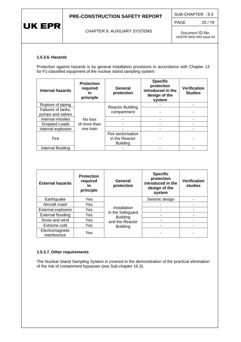
1.5.3.6. Hazards
Protection against hazards is by general installation provisions in accordance with Chapter 13 for F1-classified equipment of the nuclear island sampling system:
Internal hazards
Protection required
in principle
General protection
Specific protection
introduced in the design of the
system
Verification Studies
Rupture of piping
No loss of more than
one train
Reactor Building compartment
- - Failures of tanks, pumps and valves - -
Internal missiles - - - Dropped Loads - - -
Internal explosion - - -
Fire Fire sectorisation
in the Reactor Building
- -
Internal flooding - - -
External hazards
Protection required
in principle
General protection
Specific protection
introduced in the design of the
system
Verification studies
Earthquake Yes
Installation in the Safeguard
Building and the Reactor
Building
Seismic design - Aircraft crash Yes - -
External explosion Yes - - External flooding Yes - - Snow and wind Yes - - Extreme cold Yes - -
Electromagnetic interference Yes - -
1.5.3.7. Other requirements
The Nuclear Island Sampling System is covered in the demonstration of the practical elimination of the risk of containment bypasses (see Sub-chapter 16.3).
PRE-CONSTRUCTION SAFETY REPORT
CHAPTER 9: AUXILIARY SYSTEMS
SUB-CHAPTER : 9.3
PAGE : 21 / 79
Document ID.No. UKEPR-0002-093 Issue 04
1.6. TESTS, INSPECTION AND MAINTENANCE
1.6.1. Pre-operational testing
The inspections and pre-operational tests must be performed in order to:
• check that the system is installed in accordance with the applicable plans, drawings and specifications;
• check the proper operation (closing and opening) of remote-controlled valves on receipt of the control signals;
• check the proper operation of the heat exchangers of the Nuclear Island Sampling System;
• check that all measuring instruments (pressure, temperature, flow rate, etc.) are installed and are working properly.
1.6.2. Periodic tests
Given the safety duties of the Nuclear Island Sampling System, the only equipment requiring periodic testing are the containment isolation valves.
1.6.3. Equipment maintenance
Maintenance of the Nuclear Island Sampling System equipment consists of validation tests and calibration checks. Their frequency depends on the following:
• Technical Specifications;
• Feedback;
• Manufacturer’s recommendations.
The equipment concerned includes the boron meter, the hydrogen meter, the oxygen meter, the phase separator, the gaseous phase Chromatographer, the conductivity meters (REN [NSS] and RES) and the sodium meters. Equipment accessibility ensures that maintenance is possible in all plant states.
• Current maintenance on valves and other mechanical components of the Nuclear Island Sampling System depends mainly on manufacturer recommendations and feedback. This maintenance will be performed according to availability of the equipment, and will mainly take place during shutdown.
PRE-CONSTRUCTION SAFETY REPORT
CHAPTER 9: AUXILIARY SYSTEMS
SUB-CHAPTER : 9.3
PAGE : 22 / 79
Document ID.No. UKEPR-0002-093 Issue 04
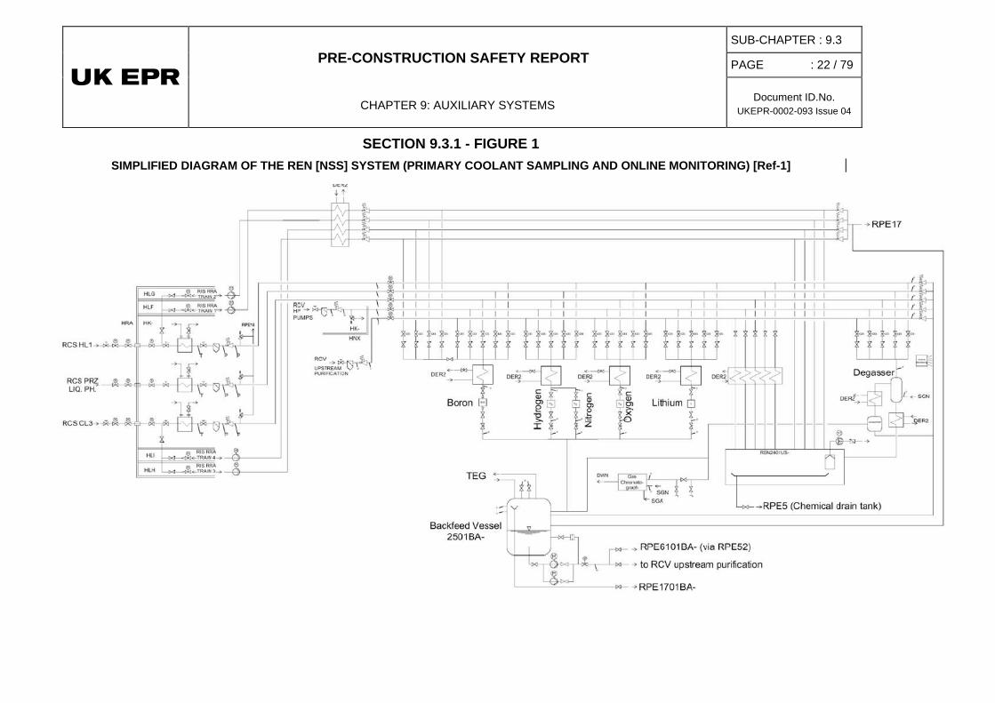
SECTION 9.3.1 - FIGURE 1 SIMPLIFIED DIAGRAM OF THE REN [NSS] SYSTEM (PRIMARY COOLANT SAMPLING AND ONLINE MONITORING) [Ref-1]
PRE-CONSTRUCTION SAFETY REPORT
CHAPTER 9: AUXILIARY SYSTEMS
SUB-CHAPTER : 9.3
PAGE : 23 / 79
Document ID.No. UKEPR-0002-093 Issue 04
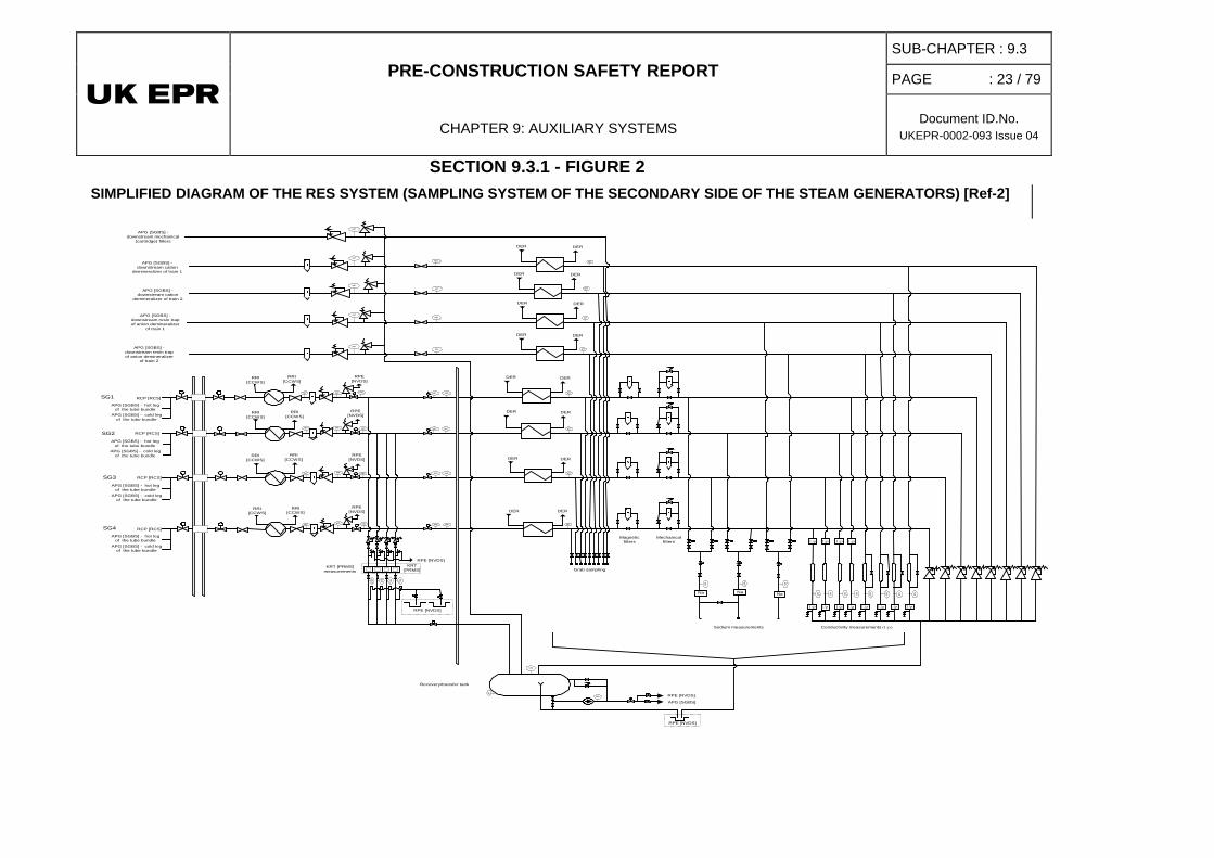
SECTION 9.3.1 - FIGURE 2 SIMPLIFIED DIAGRAM OF THE RES SYSTEM (SAMPLING SYSTEM OF THE SECONDARY SIDE OF THE STEAM GENERATORS) [Ref-2]
APG [SGBS] -downstream mechanical
(cartridge) filters
APG [SGBS] -downstream cation
demineralizer of train 1
APG [SGBS] -downstream cation
demineralizer of train 2
APG [SGBS] -downstream resin trapof anion demineralizer
of train 1
APG [SGBS] -downstream resin trapof anion demineralizer
of train 2
Na
RPE[NVDS]
RRI[CCWS]
NaNa
DER DER
RPE [NVDS]
DER DER
DER DER
DER DER
Sodium measurements Conductivity measurements (1/ρ)
Grab samplingKRT [PRMS]
measurements
Mechanicalfilters
Magneticfilters
RPE [NVDS]
KRT[PRMS]
DER DER
DER DER
DER DER
DER DER
RPE [NVDS]
APG [SGBS]
1/ρ 1/ρ 1/ρ 1/ρ
1/ρ 1/ρ 1/ρ 1/ρ 1/ρ 1/ρ1/ρ1/ρ
Recovery/transfer tank
MN
MD
MD
MD
MD MD
MD
MD
MD MP
MP
MP
MP
MDMDMD
MD
MT
MT
MT
MT MP
MP
MP
MP
MP
MP
MP
MP
MP
MD
MD
MD
MD
MT
MP
MD
MD MD
MD MD MD MD MD MD
MD MD
MT
MT
MT
MT
MT
MT
MT
MT
SG1 RCP [RCS]
APG [SGBS] - hot legof the tube bundle
APG [SGBS] - cold legof the tube bundle
RRI[CCWS]
RRI[CCWS]
RRI[CCWS]
RRI[CCWS]
RRI[CCWS]
RRI[CCWS]
RRI[CCWS]
RPE[NVDS]
RPE[NVDS]
RPE[NVDS]
RPE [NVDS]
SG2 RCP [RCS]
APG [SGBS] - hot legof the tube bundle
APG [SGBS] - cold legof the tube bundle
SG4 RCP [RCS]
APG [SGBS] - hot legof the tube bundle
APG [SGBS] - cold legof the tube bundle
RCP [RCS]
APG [SGBS] - hot legof the tube bundle
APG [SGBS] - cold legof the tube bundle
SG3
PRE-CONSTRUCTION SAFETY REPORT
CHAPTER 9: AUXILIARY SYSTEMS
SUB-CHAPTER : 9.3
PAGE : 24 / 79
Document ID.No. UKEPR-0002-093 Issue 04
2. CHEMICAL AND VOLUME CONTROL SYSTEM
2.0. SAFETY REQUIREMENTS
2.0.1. Safety Functions
2.0.1.1. Reactivity Control
During normal operation, plant startup, and plant shutdown conditions the RCV [CVCS] must, in conjunction with the Reactor Boron and Water Makeup System (REA [RBWMS]), regulate and adjust the Reactor Coolant System (RCP [RCS]) boron concentration to control power changes (in conjunction with the control rods) and to offset reactor fuel burnup.
The primary circuit boron content is adjusted by makeup via the RCV [CVCS] charging line and letdown control from the RCP [RCS]. The Reactor Boron and Water Make-up System (REA [RBWMS]) controls and regulates the makeup borated water concentration.
During an accident, the RCV [CVCS] must perform the following safety functions:
• Mitigation of a homogeneous boron dilution accident (PCC-2),
• Prevention of heterogeneous boron dilution accidents (PCC-4).
2.0.1.2. Residual Heat Removal
Under certain small break LOCA conditions, the RCV [CVCS] helps maintain the required water inventory in the RCP [RCS].
When required in post accident situations, the RCV [CVCS] helps maintain primary coolant inventory by isolation of the Reactor Coolant Pressure Boundary (RCPB).
2.0.1.3. Containment of Radioactive Substances
The RCV [CVCS] must ensure the following:
• RCP [RCS] leak tightness at the reactor coolant pump seals by injecting cooled, purified seal water to the seals and returning number 1 seal leakage to the RCV [CVCS],
• maintain a reduced charging flow, when the normal charging lines are unavailable, by injection of seal water to the number 1 seal of the reactor coolant pumps,
• appropriate RCP [RCS] water chemistry, in order to limit corrosion of the fuel rod cladding,
• auxiliary spray capability in the pressuriser,
• contribute to the prevention of steam generator (SG) overfilling (PCC-3 and PCC-4).

PRE-CONSTRUCTION SAFETY REPORT
CHAPTER 9: AUXILIARY SYSTEMS
SUB-CHAPTER : 9.3
PAGE : 25 / 79
Document ID.No. UKEPR-0002-093 Issue 04
As the RCV [CVCS] carries radioactive products in particulate or ionic form and as dissolved gases, its pressure boundary must be designed to act as a barrier to the transfer of radioactivity and to contain these products.
Under post-accident conditions, the RCV [CVCS] must ensure containment isolation.
Under post-accident conditions, in the event of a break downstream of the reactor coolant pressure boundary (RCPB) isolation valves, the RCV [CVCS] must ensure isolation of the RCPB.
2.0.2. Functional Criteria
2.0.2.1. Reactivity Control
In conjunction with the REA [RBWMS], the RCV [CVCS] must enable controlled injection of demineralised water (dilution) or boric acid (boration), so as to adjust the RCP [RCS] soluble poison content. The RCV [CVCS] must be able to control any anticipated reactivity changes, including those due to xenon effects.
When the reactor is at power, the REA [RBWMS] boration capacity via the RCV [CVCS], must be adequate to take the core to a subcritical state in cold shutdown; thereby ensuring a suitable shutdown margin including an allowance for xenon transients
The RCV [CVCS], in conjunction with the REA [RBWMS], must also be capable of controlling small reactivity changes by adjusting the RCP [RCS] boron concentration and thus following anticipated load changes, including those due to xenon effects, so that reactor fuel limits are not reached.
The RCV [CVCS] and REA [RBWMS] must be designed to protect the RCP [RCS] from the risks of homogenous or heterogeneous boron dilution, using appropriate means of detection and isolation of the Volume Control Tank (VCT) / hydrogenation station downstream line (PCC-2). The RCV [CVCS] will then be able to inject boronated water into the RCP [RCS] taking suction from the IRWST.
2.0.2.2. Residual Heat Removal
The RCV [CVCS] must keep the RCP [RCS] water inventory in the allowed range for pressuriser water level or RCP [RCS] loop level (shutdown states) for all normal operating conditions.
The RCV [CVCS] must be able to compensate for operational leaks and very small breaks of the main primary system.
The RCV [CVCS] charging capacity must be able to compensate for the RCP [RCS] contraction rate during cooldown from power state to cold shutdown state.
Charging lines and auxiliary spray must be isolated by appropriate means to maintain inventory of primary coolant inventory. In the case of a safety injection signal, the RCV [CVCS] letdown, either on RCP [RCS] loops or RIS/RRA [SIS/RHRS] lines (if the reactor is in residual heat removal mode) must be isolated by appropriate means, in particular in mid loop operation, so as not to affect safety injection efficiency.
Each RCV [CVCS] line representing the boundary of the RCP [RCS] must be provided with two isolation devices in series.

PRE-CONSTRUCTION SAFETY REPORT
CHAPTER 9: AUXILIARY SYSTEMS
SUB-CHAPTER : 9.3
PAGE : 26 / 79
Document ID.No. UKEPR-0002-093 Issue 04
2.0.2.3. Containment of Radioactive Substances
To ensure leak tightness of the reactor coolant pump seals, water from the RCV [CVCS] is injected into the number 1 seal of the reactor coolant pumps at a pressure higher than the RCP [RCS] pressure. In order to prevent damage and potential failure of the reactor coolant pump seals, the purified seal water is injected at a temperature lower than the RCP [RCS] temperature1
Each RCV [CVCS] line running through the containment must be provided with two isolation devices in series, one located inside the containment, the other located outside the containment.
.
Each RCV [CVCS] line connected to the RCP [RCS] must be provided with two RCPB isolation devices in series.
If normal pressuriser spray is unavailable, the RCV [CVCS] must be able to supply enough auxiliary spray water to reduce pressure in the RCP [RCS].
The RCV [CVCS] charging line must be isolated in the event of high water level in the steam generators (PCC-3 and PCC-4).
2.0.3. DESIGN REQUIREMENTS
2.0.3.1. Safety Classification
RCV [CVCS] safety classifications must comply with the requirements stated in Sub-chapter 3.2.
2.0.3.2. Single Failure Criterion (Active and Passive)
RCV [CVCS] components performing an F1 function must satisfy the single failure criterion to ensure a suitable degree of redundancy.
2.0.3.3. Emergency Power Sources
All motor-operated valves and HP charging pump electrical motors must be emergency-backed by diesel generators to ensure their safety functions can be performed in the event of a Loss Of Offsite Power (LOOP). The subsystem injecting chemical additives is connected to the normal power supply.
2.0.3.4. Qualification for Normal Operating Conditions
RCV [CVCS] equipment performing F1 or F2 functions must be qualified to remain operational under the related normal operating or post-accident conditions.
The corresponding requirements for components (integrity, availability, functional capability, etc.) are stated in Sub-chapter 3.6.
1 If no seal water is injected via the RCV [CVCS], thermal protection of the reactor coolant
pump seals is ensured by the thermal barrier (cooled by RRI [CCWS]), which cools the RCP [RCS] fluid flowing towards the seals. For more information on the reactor coolant pump seals, see Sub-chapter 5.4.
PRE-CONSTRUCTION SAFETY REPORT
CHAPTER 9: AUXILIARY SYSTEMS
SUB-CHAPTER : 9.3
PAGE : 27 / 79
Document ID.No. UKEPR-0002-093 Issue 04
2.0.3.5. Mechanical, Electrical and Instrumentation and Control (I&C) Classifications
The mechanical classification of the RCV [CVCS] must comply with the provisions of Sub-chapter 3.2.
The electrical classification must comply with the provisions of Sub-chapter 3.2.
The I&C classification must comply with the provisions of Sub-chapter 3.2.
In case of unavailability of the Main Control Room during PCC events, pieces of equipment of the RCV [CVCS] can be controlled from the Safety Information and Control System (MCS [SICS]) panel; that consequently avoids the actuation of safety systems (RIS [SIS], RBS [EBS]).
2.0.3.6. Seismic Classification
The RCV [CVCS] seismic classification must comply with the provisions of Sub-chapter 3.2.
2.0.4. Other Regulatory Requirements
2.0.4.1. Regulatory Documents
The RCV [CVCS] must comply with the regulatory requirements set forth in Sub-chapter 1.4.
2.0.4.2. Basic Safety Rules
Application of basic safety rules must be as stated in Sub-chapter 1.4.
2.0.4.3. Technical Guidelines
Requirements specific to the RCV [CVCS] are as stated in Sub-chapter 3.1.
2.0.4.4. Regulatory Documents Specific to the EPR
None.
2.0.5. Internal/External Hazards
2.0.5.1. Internal Hazards
The RCV [CVCS] must be protected against internal hazards, in accordance with Sub-chapter 13.2.
2.0.5.2. External Hazards
The RCV [CVCS] must be protected against external hazards, in accordance with Sub-chapter 13.1.
PRE-CONSTRUCTION SAFETY REPORT
CHAPTER 9: AUXILIARY SYSTEMS
SUB-CHAPTER : 9.3
PAGE : 28 / 79
Document ID.No. UKEPR-0002-093 Issue 04
2.0.6. Testing
2.0.6.1. Preliminary Tests
Preliminary tests must demonstrate that RCV [CVCS] design ensures the required system performance in conjunction with the REA [RBWMS].
2.0.6.2. Periodic Tests and In-service Inspection
Safety related RCV [CVCS] components must undergo periodic testing. The layout and design of the system must ensure easy access for in-service inspection and periodic testing of all class F1 and F2 equipment that is not in frequent use.
2.1. FUNCTIONAL ROLE OF THE SYSTEM
In addition to the safety functions described in section 2.0 of this sub-chapter, the RCV [CVCS] performs the following functions:
• ensure continuous control of RCP [RCS] water inventory during normal plant operating conditions by adjusting the letdown flow,
• provide purification of the reactor coolant by filtration of suspended solids and by clean-up of soluble impurities via demineralisers,
• adjust the boron concentration to control the power variations in addition to the control rods,
• enable adjustment of primary coolant chemistry and activity level by injecting chemical conditioning agents into the charging flow upstream of the charging pumps,
• control dissolved gas concentration in the RCP [RCS], via degasification of the letdown flow by the connected TEP [CSTS] system and by injecting hydrogen to the charging flow upstream of the RCV [CVCS] charging pumps,
• inject cooled and purified seal water to the reactor coolant pump shaft seals (to ensure seal cooling and integrity) and return seal leakage to the RCV [CVCS],
• provide auxiliary spray flow to the pressuriser when normal spray is unavailable or inadequate to ensure the spray function,
• take part in the performance of the Reactor Coolant Pressure Boundary (RCPB) hydrostatic pressure test,
• provide a means for RCP [RCS] filling and draining during plant shutdown, together with REA [RBWMS] and TEP [CSTS] system
• provide, if required, a high flow capability to purify the primary circuit coolant.
PRE-CONSTRUCTION SAFETY REPORT
CHAPTER 9: AUXILIARY SYSTEMS
SUB-CHAPTER : 9.3
PAGE : 29 / 79
Document ID.No. UKEPR-0002-093 Issue 04
2.2. APPLICABLE CRITERIA, HYPOTHESES AND CHARACTERISTICS [REF-1]
The Chemical and Volume Control System (RCV [CVCS]) is designed to perform the following functions:
• primary coolant volume control,
• reactivity control through adjustment of RCP [RCS] boron concentration,
• RCP [RCS] water chemistry control (in conjunction with the purification, treatment, degassing and storage subsystems), i.e.:
o control of dissolved gas concentration,
o oxygen control,
o pH control (using lithium-7 hydroxide; Li-7 OH),
o purification and filtration (to control dissolved and ionic radioactive impurities in the RCP [RCS] coolant during startup, shutdown, and normal operations).
• reactor coolant pump seal water injection and leakoff flow return,
• pressuriser auxiliary spray.
The RCV [CVCS] is also used to fill and drain the RCP [RCS] under shutdown conditions and for the RCPB hydrostatic pressure test.
To perform these functions, the RCV [CVCS] removes primary coolant via the letdown line and provides coolant makeup via the charging line:
• prior to re-injection to the RCP [RCS], the coolant discharged via the letdown line is purified and its chemical characteristics adjusted,
• make-up at the same boron concentration as the letdown flow is injected via the charging line to maintain RCP [RCS] water inventory,
• boric acid or demineralised water makeup is also provided for reactivity control.
To ensure reliable performance of the main RCV [CVCS] functions, system functional redundancy provided by the high pressure coolers and high pressure reducing stations in the letdown line and the charging pumps in the charging line, is such that the required letdown and charging flows remain available.
The "charging" function is ensured by charging flow and/or by reactor coolant pump seal water injection flow (charging with the reactor coolant pump seal water injection alone results in a reduced charging capacity).
PRE-CONSTRUCTION SAFETY REPORT
CHAPTER 9: AUXILIARY SYSTEMS
SUB-CHAPTER : 9.3
PAGE : 30 / 79
Document ID.No. UKEPR-0002-093 Issue 04
2.2.1. Primary Coolant Volume Control
The RCV [CVCS] ensures the RCP [RCS] water inventory is maintained within the allowable pressuriser level range for normal plant operation, plant power transients, RCP [RCS] heatup, and RCP [RCS] cooldown transient. This is achieved by keeping a constant charging flow and controlling the letdown flow, using the VCT as a buffer for supplying coolant or for storage of excess coolant. Larger supplies of primary coolant are available via the Reactor Boron and Water Make up System (REA [RBWMS]). For larger storage of primary coolant the Coolant Storage and Treatment System (TEP [CSTS) is used. The RCV [CVCS] has sufficient make-up capability (with the help of the REA [RBWMS]) to ensure that the primary coolant inventory can be maintained in the event of very small breaks (i.e. small break LOCA) in lines connected to the RCP.
2.2.2. Reactivity Control
The RCV [CVCS], in conjunction with the REA [RBWMS], controls boron concentration in the primary coolant, in order to control reactivity changes resulting from: coolant temperature changes between cold shutdown and full power operation, fuel burnup and burnable poisons, effects accumulation of fission products in the fuel, and xenon transients.
The RCV [CVCS} can supply borated water from the Reactor Boron and Water Make-up System (REA [RBWMS]), boric acid tanks or from the In-Containment Refueling Water Storage Tank (IRWST) to the RCP [RCS], up to the concentrations required for cold shutdown conditions or for refuelling shutdown.
2.2.3. RCP [RCS] Water Chemistry Control
In conjunction with the coolant purification system, TEP [CSTS], and the REA [RBWMS], the RCV [CVCS] controls RCP [RCS] water chemistry; in particular:
• control of the content of dissolved gases in the primary coolant for the purpose of avoiding corrosion of fuel cladding and RCP [RCS] components due to radiolysis and build up of H2 and O2,
• control of the oxygen produced by radiolysis of water in the core region by injecting dissolved hydrogen to scavenge the oxygen (Sufficient nitrogen over-pressure is maintained in the VCT to pressurise the hydrogenation station to ensure the required dissolved hydrogen content. Hydrogen is dissolved in the coolant via a hydrogenation unit in the low pressure section of the RCV [CVCS]),
• control of the pH during initial startup and subsequent operation by injecting lithium hydroxide (Li-7 OH) into the primary coolant,
• zinc injection for dose rate reduction,
• removal of radionuclides from the RCP [RCS] during plant startup, shutdown, and normal operation,
• prevention of potential premature oxygenation of the primary coolant when the RIS [SIS] is connected in RHR mode by means of hydrazine injection.
PRE-CONSTRUCTION SAFETY REPORT
CHAPTER 9: AUXILIARY SYSTEMS
SUB-CHAPTER : 9.3
PAGE : 31 / 79
Document ID.No. UKEPR-0002-093 Issue 04
2.2.4. Reactor Coolant Pump Seal Water Injection
The RCV [CVCS] ensures continuous injection of cooled and purified seal water to the number 1 seal of the reactor coolant pumps and returns the seal leakage to the RCV [CVCS]. Seal injection water is filtered to obtain the degree of purity required by the reactor coolant pump shaft seal system.
2.2.5. Pressuriser Auxiliary Spray
The RCV [CVCS] provides an auxiliary spray line to control RCP [RCS] pressure in the event of normal pressuriser spray failure. The auxiliary spray line is separate from each of the main spray lines. This line is also used to reduce primary circuit pressure in the event of an SGTR.
2.2.6. Other Functions
The RCV [CVCS] fills and drains the RCP [RCS].
The RCV [CVCS] provides water to the RCP [RCS] and controls RCP [RCS] pressure during the initial part of the RCPB hydrostatic pressure test (before the Emergency Boration System RBS [EBS] pump takes over).
2.3. SYSTEM DESCRIPTION - EQUIPMENT CHARACTERISITICS [REF-1] TO [REF-4]
Section 2.7 Figure 1 shows a simplified RCV [CVCS] flow diagram.
The RCV [CVCS] is designed to maintain continuous coolant letdown and charging flows via a letdown line and a charging line. The letdown line reduces the pressure and temperature of the letdown flow to conditions compatible with the purification subsystem and degassing system. The charging line returns the treated primary coolant to the RCP [RCS] and provides the pressuriser auxiliary spray flow when necessary. The RCV [CVCS] also provides the reactor coolant pump seal water injection flow.
2.3.1. System Description
2.3.1.1. Letdown
The letdown line removes primary coolant from Loop 1 and is equipped with RCPB isolation valves near the RCP [RCS] loops.
Letdown flow is cooled in two stages, first in the regenerative heat exchanger, then in one of the high pressure coolers. Pressure is reduced in a single stage via one of the two high-pressure reducing stations. Under normal operating conditions, a single high pressure cooler and a single high-pressure reducing station are in service. All of this equipment is located inside the Reactor Building (RB). Containment isolation for the letdown line is ensured by two motor-operated valves, one inside and the other outside the containment.

PRE-CONSTRUCTION SAFETY REPORT
CHAPTER 9: AUXILIARY SYSTEMS
SUB-CHAPTER : 9.3
PAGE : 32 / 79
Document ID.No. UKEPR-0002-093 Issue 04
When the safety injection system/residual heat removal system (RIS/RRA [SIS/RHRS]) is connected to the RCP [RCS], the connection from the RIS/RRA [SIS/RHRS] to the RCV [CVCS] is opened to allow diversion of primary coolant, whose pressure is lowered via a low pressure (LP) reducing station in the RCV [CVCS] system, for the purpose of continuous purification. The RIS/RRA [SIS/RHRS] can not be connected to the RCV [CVCS] until the primary coolant temperature is less than or equal to 55ºC [Ref-1].
In the event that the RCV [CVCS] equipment becomes unavailable in the Fuel Building (FB) or the Safeguards Building (SAB), letdown flow can be diverted to the IRWST via the Nuclear Vent and Drain System (RPE [NVDS]) in exceptional cases via a backup letdown line that connects downstream or the high pressure (HP) reducing station (in this configuration the activity level in containment increases seriously).
2.3.1.2. Purification
During normal operation, the letdown flow is routed towards the purification station. There, it passes one of the two mechanical cartridge filters, one of three mixed bed demineralisers and one resin trap. At the coolant filter, solid impurities are held back, preventing them from entering the mixed beds of the demineralisers. Two mixed bed demineralisers are operated alternately, one serving as main purification filter, and one serving as Lithium/Caesium removal filter. The third mixed bed demineraliser operates during plant startup and shutdown, during purification operations, via the Fuel Pool Cooling (and Purification) System (PTR [FPC(P)S]), and it is used for boron dilution purposes at the end of fuel cycles. The resin trap serves to retain any resin fines coming from the demineralisers.
If required, the letdown flow is routed towards the TEP4 [CDS] degasification system.
In case of high level in the volume control tank, the flow is routed towards the TEP [CSTS] system coolant storage tanks. If Lithium is to be removed from the excess reactor coolant which is routed to the TEP [CSTS] system coolant storage tanks, the demineraliser serving as the Lithium removal demineraliser and the associated resin trap, are aligned in series in the route to the coolant storage system (advanced pH control).
2.3.1.3. Volume Control Tank and Hydrogenation Station
As long as the RCP [RCS] is pressurised, letdown flow passes through the hydrogenation unit. Part of the letdown flow is diverted to the liquid phase of the VCT, where it is used to ensure a uniform boron content between the VCT and the RCP [RCS]. During normal operation the VCT gas phase is nitrogen.
When the RCP [RCS] is depressurised, the RIS/RRA [SIS/RHRS] pumps ensure sufficient flow in the RCV [CVCS] line to bypass the VCT, the hydrogenation unit, and the RCV [CVCS] charging pumps.
As long as VCT level is within its normal operating range, the charging pumps take suction mainly from the hydrogenation unit and partly from the VCT.
Makeup is provided by the REA [RBWMS] upstream of the hydrogenation unit and the VCT. The VCT is protected against overpressures by a safety valve located downstream of the tank.
PRE-CONSTRUCTION SAFETY REPORT
CHAPTER 9: AUXILIARY SYSTEMS
SUB-CHAPTER : 9.3
PAGE : 33 / 79
Document ID.No. UKEPR-0002-093 Issue 04
2.3.1.4. Charging Function
The charging pumps are supplied with cooled, purified water with the required hydrogen content. Additional lines allow suction from the IRWST in the event of low VCT level. In such cases, the hydrogenation unit and VCT are automatically isolated.
RCV [CVCS] flow downstream of the charging pumps is divided into charging flow (via the charging flow adjusting valve), seal water injection flow (via the seal water flow control valve), and charging pump (when necessary, via automatic valves on the miniflow lines). These valves automatically adjust their setting according to the main charging flow rate. Once miniflow conditions are achieved, recirculation flow is established to protect the HP Charging Pumps.
Charging flow is heated in the regenerative heat exchanger and routed to the loop 2 and loop 4 RCP [RCS] cold legs.
2.3.1.5. Reactor Coolant Pump Seal Water Injection and Leakoff Recovery
Part of RCV [CVCS] flow is routed, after filtration, to the number 1 seal of the reactor coolant pumps. Some of flow is injected into the RCP [RCS] and the balance is returned to the RCV [CVCS] through the seal leakoff recovery line. A leakoff recovery line exists for each pump, and each line is connected by a common header. The seal leakoff recovery line common header is routed to the VCT or the TEP [CSTS] system. This common header is equipped with a filter and a control valve in order to maintain sufficient pressure to avoid hydrogen degassing.
2.3.2. Major Equipment Characteristics
All parts of the RCV [CVCS] (e.g. pipework, valves, and components) that are in contact with the primary coolant are made of austenitic stainless steel. Parts of the RCV [CVCS] that are not in contact with the primary coolant may be constructed of materials other than austenitic stainless steel (e.g. pump motors).
To avoid coolant leakage, all pipework connections and joints must be welded except where flanges are required to facilitate dismantling for maintenance or pressure testing.
2.3.2.1. Regenerative Heat Exchanger
The regenerative heat exchanger is designed to recover the heat from the letdown flow and use it to heat the charging flow. The letdown flow rate used as the basis for heat exchanger design is the maximum rate for RCP [RCS] heatup with two RCV [CVCS] pumps in service.
2.3.2.2. High-Pressure Coolers
The high pressure coolers use the component cooling water system (RRI [CCWS]) to cool the letdown flow to a temperature acceptable for demineraliser operation. Each HP cooler is capable of cooling all the letdown flow precooled in the regenerative heat exchanger, during normal plant operation and RCP [RCS] cooldown. The HP coolers are designed with a 2 x 50% capacity to accommodate RCP [RCS] heatup and 2 x 100% capacity to accommodate the high purification and degassing rate required during hot shutdown or normal power conditions. Both the regenerative and the HP coolers are designed to allow letdown (small letdown flow) without charging and in the case of charging without letdown the flow bypasses the regenerative heat exchanger.

PRE-CONSTRUCTION SAFETY REPORT
CHAPTER 9: AUXILIARY SYSTEMS
SUB-CHAPTER : 9.3
PAGE : 34 / 79
Document ID.No. UKEPR-0002-093 Issue 04
Primary coolant flows through the tube side of the HP coolers, while cold component cooling water system (RRI [CCWS]) water flows through the shell side.
Each high-pressure cooler is equipped with two rupture disks (upstream and downstream of the heat exchangers in the RRI [CCWS]) intended to protect the RRI [CCWS] from a pressure wave in the event of heat exchanger tube rupture. In such cases, information routed to the control room (temperature, flow and activity measurements along with RRI [CCWS] tank level readings) allows the identification and the isolation of the defective heat exchanger.
2.3.2.3. High-Pressure Reducing Stations
The HP reducing stations are designed to reduce pressure to a value compatible with design pressures for the purification subsystem and treatment system. It is possible to operate the two HP reducing stations in parallel during startup and shutdown. In this case, pressuriser level is automatically controlled by only one HP reducing station and the other reducing station is controlled manually. The downstream pressure is maintained on the HP reducing stations to ensure that the letdown flow remains in the liquid phase.
2.3.2.4. Volume Control Tank and Hydrogenation Station
The VCT must perform the following functions:
• provide the control mechanism for managing the expansion of primary coolant inventory that cannot be accommodated by the pressuriser during plant heatup or load changes This function is performed by actuating a control valve to direct letdown flow to the coolant storage and treatment system (TEP [CSTS]),
• provide a volume adequate to ensure continuous flow to the charging pump suction prior to automatic realignment to IRWST suction, following loss of letdown flow,
• enable correct operation of the automatic Reactor Boron and Water Makeup System (REA [RBWMS]) in the even t that the VCT Level is too low.
The VCT gas phase is made up of nitrogen (constantly sweeped by TEG) at a pressure ranging from 1 to 4 bar abs during normal operation according to the required amount of hydrogen in the Gas Separator. Hydrogen is dissolved in the coolant via a hydrogenation unit in the low pressure section of the RCV [CVCS].
The VCT is connected to the gaseous waste processing system (TEG [GWPS]) and the nitrogen distribution system. Fission gases and hydrogen are removed from the VCT by continuous sweeping of the gas phase to the TEG [GWPS].
2.3.2.5. Charging Pumps
Charging flow must be adequate to offset the following:
• letdown flow during normal plant operation, load follow, and controlled cooldown transients; the two charging pumps can be operated in parallel
• loss of RCP [RCS] inventory due to limited leakage.
PRE-CONSTRUCTION SAFETY REPORT
CHAPTER 9: AUXILIARY SYSTEMS
SUB-CHAPTER : 9.3
PAGE : 35 / 79
Document ID.No. UKEPR-0002-093 Issue 04
Charging pumps are of the multi-stage, vertically-mounted, centrifugal type. They are connected to a miniflow line for protection purposes. The pumps are sealed by a double mechanical seal and in the event of a loss of seal water supply a seal buffer tank provides several hours of seal injection flow to the pump seals.
2.3.2.6. Relief Valves
Safety relief valves are installed on lines and components whose pressure could exceed the design pressure as a result of operator error or component malfunction.
Each valve must have a capacity equal to the maximum flow rate in the protected line and its set pressure must be a value which will ensure the pressure of the line does not exceed the maximum allowable line pressure.
2.4. OPERATING CONDITIONS
2.4.1. Normal Plant Operation
2.4.1.1. General
Normal RCV [CVCS] operation corresponds to normal plant operation, which includes baseload and load follow conditions.
In normal operation, RCV [CVCS] configuration is as follows: Part of the primary coolant is discharged through the high pressure letdown line. The regenerative heat exchanger, one high-pressure cooler, one high-pressure reducing station, and one charging pump are in service. The letdown flow is routed out of the Reactor Building to the purification station and the hydrogenation unit. The coolant is then returned to the RCP [RCS] via the normal charging line. During all plant operating modes the RCV [CVCS] injection flow is injected into the RCP [RCS] at the Loop 2 and Loop 4 cold legs, and the reactor coolant pump seals. In the case of testing, a steam generator tube rupture, or too high reactor coolant pressure the injection flow may be diverted to the pressuriser instead of injection to Loop 2 and Loop 4. Seal injection will be continued in this operating mode.
Seal water injection flow to the reactor coolant pumps passes through a filter. The pressuriser auxiliary spray flow path is isolated. In baseload operation, the RCV [CVCS] performs the following functions: volume control, chemical control, reactor coolant purification and reactivity control in conjunction with the REA [RBWMS].
2.4.1.2. Volume Control
In normal operation, RCP [RCS] coolant mass is kept constant by regulating letdown flow with a constant charging flow.
During transients, the primary coolant expands or contracts as its temperature rises or falls. As the pressuriser absorbs these expansions and contractions its level changes within a predetermined range. The setpoints depend on power level.
If VCT level exceeds MAX1, part of the letdown flow is diverted to the TEP [CSTS]. If MAX2 level is reached then all letdown flow is diverted to the TEP [CSTS]. When charging flow exceeds letdown flow, if VCT level reaches low level MIN1, this initiates automatic makeup from the REA [RBWMS].
PRE-CONSTRUCTION SAFETY REPORT
CHAPTER 9: AUXILIARY SYSTEMS
SUB-CHAPTER : 9.3
PAGE : 36 / 79
Document ID.No. UKEPR-0002-093 Issue 04
If this action is insufficient and/or inoperative, a very low level causes charging pump suction to switch to the IRWST (this is not normal operation).
2.4.1.3. Reactivity Control
If power changes take place and the new power level is maintained for a long period, the boron concentration may need to be adjusted to offset xenon effects and ensure an adequate shutdown margin. This entails injection of borated or demineralised water from the REA [RBWMS] (via the RCV [CVCS]).
2.4.1.4. Chemical Control
The purification station can be used for as long as the letdown flow temperature downstream of the heat exchangers remains below 60°C. If it exceeds 60°C, the purification station is automatically bypassed.
Lithium Hydroxide (Li-7 OH) is added automatically by an injection device connected to the charging pump suction header, for primary coolant pH control. The Li-7 OH hydroxide can be removed from the system by one of the mixed bed demineralisers during normal plant operation.
Coolant hydrogen content is controlled by the hydrogenation unit located in the Low Pressure section of the RCV [CVCS] upstream of the charging pumps. Oxygen produced in the core by radiolysis of water is thus scavenged by hydrogen added to the primary coolant. Other chemicals may be used during plant startup and shutdown to control corrosion products in the primary system and to minimise ex-core radiation fields.
2.4.2. Cold Shutdown
During normal cold shutdown, the normal letdown path is through the regenerative heat exchanger and one or two High Pressure coolers. As long as RCP [RCS] pressure exceeds 25 bar abs. or 55°C, the RIS/RRA [SIS/RHRS]-RCV [CVCS] connection line cannot be opened. When the last reactor coolant pump is stopped, the HP coolers are isolated and letdown flow is routed from the RIS/RRA [SIS/RHRS] heat exchangers through the RCV [CVCS] Low Pressure reducing station, the RCV [CVCS] hydrogenation unit, and the VCT. Although letdown flow passes through the hydrogenation unit, hydrogenation does not take place in this plant state. Part of the flow upstream of the hydrogenation unit is directed to the VCT. From there, it is returned to the common suction header of the HP charging pumps and injected through the normal charging line (with charging pumps in service).
In ¾ loop operation, the RCP [RCS] level control system acts on the RCV [CVCS] LP reducing station to ensure a suitable water inventory for operation of the LHSI pumps. When RCP [RCS] loop level is too low, the letdown is isolated.
2.4.3. Hot Shutdown
The RCV [CVCS] operates in the same way as during normal operation. RCV [CVCS] letdown flow rate may be increased as needed for purification/degassing. Depending on the duration of hot shutdown, it may be necessary to adjust boron concentration to account for xenon effects in the core.

PRE-CONSTRUCTION SAFETY REPORT
CHAPTER 9: AUXILIARY SYSTEMS
SUB-CHAPTER : 9.3
PAGE : 37 / 79
Document ID.No. UKEPR-0002-093 Issue 04
2.4.4. Plant Startup
Initial plant conditions before startup are as follows:
• RCP [RCS] is cold and depressurised,
• RCP [RCS] boron concentration is at its cold shutdown value,
• RIS/RRA [SIS/RHRS] cooling is active,
• RCV [CVCS] is filled with coolant whose boron concentration is the cold shutdown value,
• Low Pressure reducing station on the RIS/RRA [SIS/RHRS]-RCV [CVCS] line is in service.
During plant startup, the RCV [CVCS] is used to:
• fill the RCP [RCS],
• provide the required reactor coolant pump seal water injection flow,
• control coolant volume and chemistry during RCP [RCS] heatup.
RCP [RCS] degassing takes place via the RCV [CVCS] by diverting letdown flow to the TEP [CSTS] for removal of oxygen (mainly after refueling) from the RCP [RCS].
The VCT nitrogen blanket is maintained to ensure the appropriate pressure required for controlling the dissolved oxygen content during operation at power.
During RCP [RCS] pressurisation, the RIS/RRA [SIS/RHRS]-RCV [CVCS] connection line is open when the RIS/RRA [SIS/RHRS] system is connected to the RCP [RCS] in residual heat removal mode. RCP pressure, in monophasic mode, is controlled by variation of the letdown flow through the LP reducing station.
When RCP [RCS] pressure is greater than 25 bar the RIS/RRA [SIS/RHRS]-RCV [CVCS] connection can be isolated and letdown via the normal letdown process implemented.
RCP [RCS] heatup makes use of the reactor coolant pumps. Prior to the RCP [RCS] temperature reaching 120°C, Li-7 OH can be added via charging pump suctions, to control the coolant pH.
When RCP [RCS] is diphasic, the pressure is controlled by its heaters and normal spray.
Assuming that the heatup rate for thermal design of the RCV [CVCS] heat exchangers is 25°C/h, excess letdown flow resulting from primary coolant expansion is directed to the TEP [CSTS]. Throughout the startup phase, the pressuriser is two-phase; and pressuriser water level is kept at its setpoint value.
During this phase, seal water injection flow rate is maintained at 4 x 1.8 t/h. [Ref-1]

PRE-CONSTRUCTION SAFETY REPORT
CHAPTER 9: AUXILIARY SYSTEMS
SUB-CHAPTER : 9.3
PAGE : 38 / 79
Document ID.No. UKEPR-0002-093 Issue 04
2.4.5. Transition from Hot Shutdown to Hot Standby
RCP [RCS] boric acid content is reduced to reach reactor criticality conditions. Dilution is performed by the REA [RBWMS] via the RCV [CVCS].
2.4.6. Plant Shutdown
After control rod insertion and during RCP [RCS] cooldown/depressurisation, primary coolant boron concentration is increased to the final plant state to be achieved. The REA [RBWMS] provides borated water to the RCV [CVCS] to offset coolant contraction and minimise waste.
The primary coolant must also be degassed to remove fission gasses and reduce the H2 content. This operation is performed by diverting the letdown flow to the TEP [CSTS].
2.4.7. Reactor Cooldown
Initial cooldown takes place via the steam generators and the turbine bypass system. To maintain the minimum letdown flow required for purification and degassing along with the required level in the pressuriser at a cooling rate of 50°C/h, two RCV [CVCS] charging pumps are necessary to offset coolant contraction. [Ref-1]
When the primary coolant temperature reaches approximately 120°C, the RIS/RRA [SIS/RHRS], is connected to the RCP [RCS]; cooldown then takes place via the RIS/RRA [SIS/RHRS] heat exchangers. When temperature downstream of these heat exchangers is low enough and primary coolant pressure decreases, the HP letdown stations can be isolated and the RIS/RRA [SIS/RHRS]-RCV [CVCS] connection line opened.
During single phase operation of the pressuriser, RCP [RCS] depressurisation is achieved via either the high or low pressure reducing station.
After final depressurisation of the RCP [RCS], the RCV [CVCS] pumps can be shut down and bypassed. Seal water injection flow to each of the first stage reactor coolant pump seals is provided, when necessary, by the LHSI pumps via the purification line.
2.5. PRELIMINARY SAFETY ANALYSIS
2.5.1. Brief Description of Safety Functions
The RCV [CVCS] is involved in the following safety functions:
• Containment isolation is performed by safety class F1A valves. Containment penetrations for the letdown line and the seal leakoff recovery line are each isolated by automatic closure of two motor-operated valves: one in the Reactor Building and the other in the Fuel Building,
• The containment is isolated at each of the charging and the reactor coolant pump seal water injection lines by a motor-operated valve located in the Fuel Building and a check valve located in the Reactor Building,
PRE-CONSTRUCTION SAFETY REPORT
CHAPTER 9: AUXILIARY SYSTEMS
SUB-CHAPTER : 9.3
PAGE : 39 / 79
Document ID.No. UKEPR-0002-093 Issue 04
• Possible sources of dilution originating from the RCV [CVCS] and the auxiliary systems connected upstream of the VCT and the hydrogenation unit are isolated by class F1 devices; however isolation valves that align the IRWST to the charging pumps are classified as F2. A boron meter station (four boron concentration measurements) downstream of the charging pump discharge header, but upstream of the reactor coolant pump seal water injection branch, is used to detect dilutions. The boron meter station is class F1,
• RCV [CVCS] isolation devices on the RCP [RCS] serve to isolate the RCPB. These parts of the RCV [CVCS] are therefore class F1,
• When a high SG level is detected following an SGTR, the charging line receives an automatic closure signal to avoid SG overfilling and abnormal pressurisation,
• The following RCV [CVCS] functions are class F1:
o containment isolation,
o RCPB isolation,
o mitigation of undesired heterogeneous or homogeneous boron dilutions,
o charging line isolation on high SG level.
2.5.2. Compliance with Design Requirements
2.5.2.1. Safety Classification
Compliance of equipment design and construction with rules for safety classification is detailed in Sub-chapter 3.2.
2.5.2.2. Single Failure Criterion (Redundancy)
The single (active or passive) failure criterion is not applicable, except to parts of the system involved in F1 functions. However, functional redundancy is ensured for the charging function, to protect against failure of an active component in the associated subsystems. This means that the charging pumps, the boric acid supplies, and the corresponding active valves are redundant for the boration function.
2.5.2.3. Qualification
RCV [CVCS] equipment is qualified in accordance with the requirements stated in Sub-chapter 3.6.
2.5.2.4. Instrumentation and Control (I&C)
Compliance of equipment design and construction with rules for safety classification is detailed in Sub-chapter 3.2.

PRE-CONSTRUCTION SAFETY REPORT
CHAPTER 9: AUXILIARY SYSTEMS
SUB-CHAPTER : 9.3
PAGE : 40 / 79
Document ID.No. UKEPR-0002-093 Issue 04
2.5.2.5. Emergency Power Supplies
Power for active charging and letdown components is supplied by independent trains and backed up by diesel generators.
2.5.2.6. Hazards
The rules and criteria for protection against internal and external hazards are stated in the relevant chapter (see Chapter 13).
Internal hazards and their protection principles are described in Sub-chapter 13.2. Protection devices are necessary both inside and outside the containment if high energy RCV [CVCS] pipework could potentially cause significant damage to engineered safeguards or containment systems.
Equipment on which buildup of radioactive elements is possible (filters and associated pipework) are placed in bunkers with restricted access and radiation protection.
Physical and electrical separation is provided for actuators linked to a safety function (i.e. RCP [RCS] break without safety injection signal). For example: the VCT requires two isolation valves and each is installed in a different building – one in Fuel Building 1 and the other in Fuel Building 2. They are also powered by different electrical trains.
2.5.2.7. Other Requirements
The RCV [CVCS] is included in demonstrating the practical elimination of containment bypass risk (see Sub-chapter 16.3).
2.6. SPECIFIC TEST REQUIREMENTS
As part of plant operation, periodic tests, inspections and instrument calibrations are performed to monitor the state and performance of equipment.
Most of the components of the system are used regularly. Its availability and performance is monitored via the main control room and/or local indications.
2.7. SIMPLIFIED FLOW DIAGRAM
See Section 9.3.2 - Figure 1 and Figure 2.
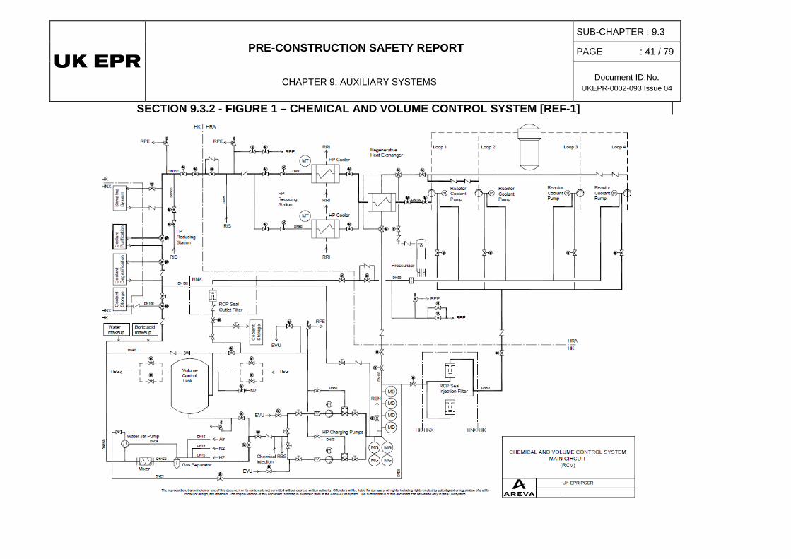
PRE-CONSTRUCTION SAFETY REPORT
CHAPTER 9: AUXILIARY SYSTEMS
SUB-CHAPTER : 9.3
PAGE : 41 / 79
Document ID.No. UKEPR-0002-093 Issue 04
SECTION 9.3.2 - FIGURE 1 – CHEMICAL AND VOLUME CONTROL SYSTEM [REF-1]
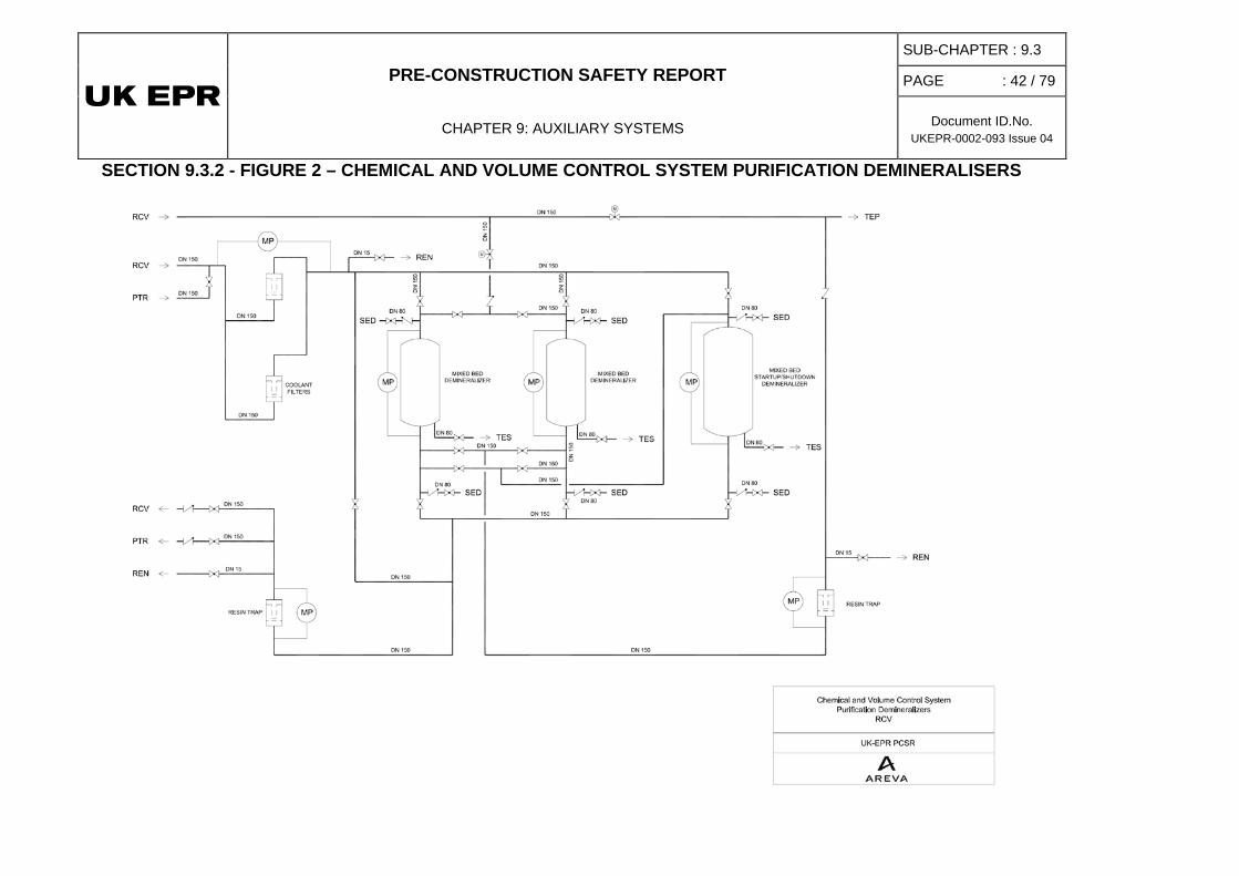
PRE-CONSTRUCTION SAFETY REPORT
CHAPTER 9: AUXILIARY SYSTEMS
SUB-CHAPTER : 9.3
PAGE : 42 / 79
Document ID.No. UKEPR-0002-093 Issue 04
SECTION 9.3.2 - FIGURE 2 – CHEMICAL AND VOLUME CONTROL SYSTEM PURIFICATION DEMINERALISERS

PRE-CONSTRUCTION SAFETY REPORT
CHAPTER 9: AUXILIARY SYSTEMS
SUB-CHAPTER: 9.3
PAGE : 43 / 79
Document ID.No. UKEPR-0002-093 Issue 04
3. COOLANT PURIFICATION, DEGASIFICATION, STORAGE AND TREATMENT SYSTEM
3.0. SAFETY REQUIREMENTS
3.0.1. Safety functions
The Coolant Storage and Treatment System (TEP [CSTS]) does not play a direct role in fulfilling the three basic safety functions.
However, since the TEP [CSTS] system conveys fluids containing radioactive products, its pressure envelope must be designed to contain radioactive products.
This system also plays a part in retaining radioactive materials in normal operations, thus reducing release into the environment.
3.0.2. Functional criteria
Since the Coolant Storage and Treatment System (TEP [CSTS]) does not fulfil an active safety function, there are no safety-related functional criteria.
3.0.3. Design requirements
3.0.3.1. Requirements from safety classifications
• Safety classifications
The Coolant Storage and Treatment System (TEP [CSTS]) is safety classified in accordance with the classification specified in Sub-chapter 3.2.
• Single failure criterion (active and passive)
Not applicable.
• Emergency power supply
Not applicable.
• Qualification for operating conditions
Not applicable.
• Mechanical, electrical and instrumentation and control classification
The mechanical, electrical and instrumentation and control classifications for the Coolant Storage and Treatment System (TEP [CSTS]) are defined according to the classification specified in Sub-chapter 3.2.
PRE-CONSTRUCTION SAFETY REPORT
CHAPTER 9: AUXILIARY SYSTEMS
SUB-CHAPTER: 9.3
PAGE : 44 / 79
Document ID.No. UKEPR-0002-093 Issue 04
• Seismic classification
The Coolant Storage and Treatment System (TEP [CSTS]) is not seismically classified.
• Surveillance tests
The Coolant Storage and Treatment System (TEP [CSTS]) does not fulfil any active safety function and is designed for normal unit operations when it is used on a regular basis. No need for surveillance tests has been identified at this stage.
3.0.3.2. Other regulatory requirements
Not applicable.
3.0.3.3. Internal/external hazards
Internal hazards: see Sub-chapter 13.2.
External hazards: see Sub-chapter 13.1.
3.1. SYSTEM ROLE
In order to simplify the description, the Coolant Storage and Treatment System (TEP [CSTS]) is divided into four sub-systems:
• the coolant storage and supply system,
• the coolant treatment system,
• the coolant purification system and
• the coolant degasification system.
The coolant storage and supply system fulfils the following operating functions:
Coolant Storage and Supply System (TEP1 [CSS])
• Receipt and storage of the reactor coolant originating directly from systems circulating reactor coolant, which is discharged during normal operation of the plant as a result of the need to compensate the burn-up during the cycle, load variations (including load follow operations) and start-up and shutdown transients.
• Receipt and storage of reactor coolant collected by the Vent and Drain System (recyclable primary drains) RPE [NVDS].
• Receipt and storage of reactor coolant collected by the Vent and Drain System (safety valve recovery) RPE [NVDS].
• Storage and supply of deaerated demineralised water for reactor coolant makeup and reactor coolant exchange via the REA [RBWMS] (Reactor Boron and Water Makeup System).
PRE-CONSTRUCTION SAFETY REPORT
CHAPTER 9: AUXILIARY SYSTEMS
SUB-CHAPTER: 9.3
PAGE : 45 / 79
Document ID.No. UKEPR-0002-093 Issue 04
The coolant purification system extracts solid and ionic impurities (such as fission and activation products e.g. caesium) as well as lithium upstream of the coolant treatment system TEP3.
Coolant Purification System (TEP2 [CPS])
The coolant treatment system TEP3/5/6 [CTS] fulfils the following functions:
Coolant Treatment System (TEP3/5/6 [CTS])
• Separation of reactor coolant, which is discharged during normal operation of the plant and which is temporarily stored by the TEP1 [CSS] system, into borated water with a boron concentration of 7000 ppm B (concentrates) and demineralised water (distillates) for further re-use in the reactor coolant system.
• Degassing of distillates before re-injection into the Reactor Coolant System or their release from the plant (in the event of high tritium content) and degassing of the SED demineralised water makeup needed to compensate for any release.
Following separation into boric acid and demineralised water, the reactor coolant is re-introduced into the Reactor Coolant System via the Reactor Boron and Water Makeup System (REA [RBWMS]) and the Chemical and Volume Control System (RCV [CVCS]).
The gaseous effluent derived from degassing of distillates is transferred to the Gaseous Waste Processing System (TEG [GWPS]) where its activity is reduced before release.
The purpose of the coolant degasification system is to extract the gases dissolved in the reactor coolant which cannot be extracted by ion exchange or filtering for direct re-injection via the RCV [CVCS] without any change to boron concentration. The degasification is generally performed:
Coolant Degasification System (TEP4 [CDS])
• Before the Reactor Coolant System (RCP [RCS]) is opened for refuelling or maintenance in order to prevent release of active gases as well as hydrogen from the reactor coolant into the containment atmosphere.
• After the Reactor Coolant System has been closed e.g. at the end of an outage to remove the oxygen dissolved in the coolant which could lead to corrosion of the materials in the RCP [RCS].
• During power operation of the plant, to reduce the concentration of noble gases and other gases, if the reactor coolant design activity limit is being approached, or if it is required to maintain coolant chemistry.
3.2. DESIGN BASIS [REF-1]
3.2.1. Coolant storage and treatment systems
The Coolant Storage and Treatment Systems are designed for normal plant operations: base load operations, load follow operations and operational transients are taken into account.
PRE-CONSTRUCTION SAFETY REPORT
CHAPTER 9: AUXILIARY SYSTEMS
SUB-CHAPTER: 9.3
PAGE : 46 / 79
Document ID.No. UKEPR-0002-093 Issue 04
3.2.1.1. Coolant storage and supply system design
The following operational transients are considered in storage and supply system design: [Ref-1]
• short hot shutdown approx. 6-8 hours (start-up at maximum xenon),
• long hot shutdown approx. 90 hours (xenon-free start-up),
• cold shutdown (xenon-free start-up),
• refuelling shutdown (including pressure testing prior to plant start-up).
Total storage capacity is governed by the quantity of demineralised water needed for an immediate return to full power from the xenon-free cold shutdown state, close to end-of-cycle conditions. The volume of coolant released during the start-up transient (heating and dilution) must be taken into account.
Storage Capacity
Full operability of the coolant treatment unit TEP3/5/6 [CTS] is assumed during the start-up transient.
In addition, the storage capacity is designed to provide a 2-day autonomy period during load follow operations in the event of unavailability of the coolant treatment system TEP3/5/6 [CTS].
Furthermore, it must be possible to achieve immediate start-up from hot shutdown to full power throughout a cycle (Restrictions are acceptable for shutdowns of < 8 hours in EOC (end-of-cycle) conditions. In this case, considering the brevity of the transient, no credit is taken from the treatment system [Ref-1]
Lastly, the coolant storage and supply system is designed for immediate return to cold shutdown from any normal operating conditions. The following measures are made regarding storage capacity:
Provisions for Undelayed Return to Cold Shutdown
• permanent water reserve to compensate for coolant contraction,
• permanent storage capacity to receive coolant discharged in consequence of boration.
So as to prevent air dissolving in the coolant and to prevent any build-up of flammable gas mixtures in the system free volumes, the tanks are constantly swept with nitrogen taken from the Gaseous Waste Processing System (TEG [GWPS]).
Furthermore, the tanks are operated at a pressure slightly lower than atmospheric pressure (0.8 bar a) to prevent any hydrogen leakage from the system. The storage tanks are equipped with a safety valve for protection against overpressure.
3.2.1.2. Coolant treatment system design
The treatment capacity must satisfy the demand for reactor coolant resulting from the following:
• daily fuel burnup up to EOC conditions,
PRE-CONSTRUCTION SAFETY REPORT
CHAPTER 9: AUXILIARY SYSTEMS
SUB-CHAPTER: 9.3
PAGE : 47 / 79
Document ID.No. UKEPR-0002-093 Issue 04
• load follow operations up to 80% of natural cycle duration.
For load follow operations over 0 to 80% of natural cycle duration, standard variations of 60 to 100% NP (nominal power) are considered for design purposes.
For possibly more stringent load follow programs involving power levels in the range of 25% to 60% NP (nominal power) (abnormal load follow operations) and/or several cycles per day, restrictions are accepted.
The treatment efficiency is designed to ensure production of concentrates (boric acid: 7000 ppm B) and distillates (demineralised water with maximum boron concentration < 5 ppm B) with the required quality for recycling to the Reactor Coolant System.
The degasification unit of the coolant treatment system allows re-use of degasified distillates in the Reactor Coolant System or discharge to the 8TEU [LWPS] (Liquid Waste Processing System) (in the case of high tritium content).
So as to prevent air from dissolving in the reactor coolant and to prevent any accumulation of flammable gas mixtures in the system free volumes, the tanks are constantly swept with nitrogen taken from the Gaseous Waste Processing System (TEG [GWPS]) when the system is shut down.
The treatment system components are fitted with safety valves for overpressure protection.
Downstream of the evaporator, the boric acid concentration is around 7000 ppm B (4% boric acid). The corresponding crystallisation temperature is 15°C and the parts of the system in which boric acid circulates must be kept above this temperature. The ventilation system ensures an ambient temperature above this limit. [Ref-1]
3.2.2. Coolant purification
Purification system requirements are:
• Removal of the activation and fission products which have not been retained in the RCV [CVCS] purification demineraliser,
• Removal of ionic and colloidal impurities so as to prevent an increase in concentration of impurities in the treatment plant and to prevent them being transferred into the Reactor Coolant System.
The mixed-bed ion exchanger is designed to accommodate the flow rate from the evaporator feed pump of TEP3/5/6 [CTS] (treatment unit inlet flow).
As the resins are sensitive to high temperatures, measures (like interlocks which isolate the purification chain) are taken to prevent effluent temperature from exceeding 60°C.
The cartridge filter downstream of the mixed-bed ion exchanger helps to hold back resin fines coming from the demineralisers or particles passing the demineraliser in order to prevent any carryover of impurities into the treatment unit TEP3/5/6 [CTS] and also re-introduction into the Reactor Coolant System.
PRE-CONSTRUCTION SAFETY REPORT
CHAPTER 9: AUXILIARY SYSTEMS
SUB-CHAPTER: 9.3
PAGE : 48 / 79
Document ID.No. UKEPR-0002-093 Issue 04
3.2.3. Coolant degasification
During power operation the coolant degasification system is used occasionally to reduce the concentration of noble and other gases if the pre-determined activity of the reactor coolant is approached.
A degasification process is furthermore required when the RCP [RCS] is to be opened for a refuelling outage or any maintenance or repair work that needs to be performed on components containing primary coolant.
During outages with an open RCP [RCS] a certain amount of air is dissolved in the primary coolant. During and at the end of an outage the dissolved gases need to be removed from the coolant by the Coolant Degasification System to avoid corrosive attack on the materials of the pressure retaining boundaries of the RCP [RCS]. In this case the Coolant Degasification System allows operation independent of the Gaseous Waste Processing System by connections to the Nitrogen Distribution System and the Heating, Ventilating and Air Conditioning System. For chemical conditioning of the primary coolant, hydrogen is added to the reactor coolant in the Chemical and Volume Control System. Additionally, other non-radioactive gases (mainly consisting of nitrogen) may also be dissolved in the RCP [RCS]. Hydrogen and other gases are removed together with the radioactive gases when the system is operated for one of the purposes mentioned above. If removal of inert gases is required for chemical conditioning of the reactor coolant, the Coolant Degasification System can be operated at any time during power operation of the plant.
Since the Coolant Degasification System only fulfils operating functions, only one train is required. Further, there is no redundancy provided, as the system is only operated intermittently and thus requirements on availability are less stringent.
The coolant degasification system can be operated in the following range of the flow rate:
Design flow rate
degasification rate 20 kg/s (nominal)
30 kg/s (maximum)
10 kg/s (minimum)
At the outlet of the degasifier column the concentration of the gases dissolved in the coolant are reduced by a factor of > 100. The boron concentration and the temperature remain unchanged.
Purge Gas
At the inlet to the degasifier column the purge gas delivered by the Gaseous Waste Processing System has a nitrogen concentration > 96% vol.
If the system is connected to the Nitrogen Distribution System, the purge gas consists of 100% nitrogen and does not contain any radioactivity.
Mixing with the gases expelled from the degasified coolant, (mainly H2) the gas at the outlet of the vacuum pump unit, results in an increased hydrogen content. The concentration is still well below 4% vol. [Ref-1]

PRE-CONSTRUCTION SAFETY REPORT
CHAPTER 9: AUXILIARY SYSTEMS
SUB-CHAPTER: 9.3
PAGE : 49 / 79
Document ID.No. UKEPR-0002-093 Issue 04
3.3. EQUIPMENT DESCRIPTION AND CHARACTERISTICS [REF-1] TO [REF-6]
3.3.1. System description [Ref-1] [Ref-2]
3.3.1.1. Coolant storage and supply system
A simplified flow diagram of the coolant storage and supply system can be found in Section 9.3.3 - Figure 1.
The coolant storage and supply system is mainly composed of:
• 6 identical storage tanks,
• 1 borated water line (primary coolant),
• 1 demineralised water line.
Each tank can hold primary coolant (received via the borated water line) or demineralised water (received via the demineralised water line). These tanks are cylindrical pressure vessels.
The borated water line is to transfer the borated water from the RCV [CVCS] and the Nuclear Vent and Drain System (recyclable primary drains) to the storage tanks, and from the storage tanks to the coolant treatment unit.
The demineralised water line transfers the demineralised water from the treatment unit to the storage tanks, and from the storage tanks back to the RCV [CVCS] via the reactor boron and water make-up system.
The transfer from one tank to another can be performed via a bypass line between the borated water line and the demineralised water line, using one of the evaporator feed pumps of the coolant treatment unit.
So as to prevent accumulation of flammable gas mixtures in the system free spaces, the tanks are constantly swept with nitrogen taken from the Gaseous Waste Processing System. Additionally, the tanks are operated below atmospheric pressure (0.8 bar a) to prevent hydrogen leakage from the system.
The primary coolant admitted into the borated water line comes from:
System inlets
• The Chemical and Volume Control System via the 3-way valve upstream of the volume control tank (VCT)
• The Nuclear Vent and Drain System (recyclable primary vents) (RPE [NVDS]).
Reactor coolant collected by the Nuclear Vent and Drain System (safety valve discharge unit) (RPE [NVDS]) is directly routed to the 2 tanks dedicated out of the 6, via dedicated inlet nozzles at the top of the tanks.
PRE-CONSTRUCTION SAFETY REPORT
CHAPTER 9: AUXILIARY SYSTEMS
SUB-CHAPTER: 9.3
PAGE : 50 / 79
Document ID.No. UKEPR-0002-093 Issue 04
The demineralised water admitted into the demineralised water line comes from the coolant treatment system. A connection is provided to the Demineralised Water Distribution System (SED) for initial filling of the tanks or for other purposes such as flushing, rinsing, etc.
Primary coolant stored in the tanks is sent to the coolant treatment system for separation into boric acid and demineralised water via the borated water line.
System outlets
Demineralised water stored in the tanks is returned to the Reactor Boron and Water Makeup System (REA [RBWMS]) by the tank connected to the demineralised water line.
3.3.1.2. Coolant purification system
The purification system is composed of:
• 1 mixed-bed ion exchange unit filled initially with H+ and OH- charged resins,
• 1 cartridge filter (resin trap).
The mixed-bed ion exchange unit and the downstream resin trap are located between the coolant storage tanks and the coolant treatment system.
3.3.1.3. Coolant treatment system
A simplified flow diagram of the coolant treatment system, with the purification system can be found in Section 9.3.3 - Figure 2.
The TEP3/5/6 [CTS] system is comprised of one 100% evaporation unit for separation of reactor coolant into demineralised water and boric acid and one 100% degasification unit. However for reasons of availability, the active components that are important for the process (pumps and control valves) are installed with redundancy.
The coolant treatment system is composed of:
• 2 evaporator feed pumps (2 x 100%)
• One evaporation unit including: a recuperative boric acid cooler, a recuperative preheater, an evaporator, an electrical preheater, a boric acid column, two recirculation pumps (2 x 100%) and the associated boric acid concentration measuring system, vapour compressors with seal water tank, seal water pumps and a seal water cooler, a condensate collector, a condensate cooler, a condenser, a condensate tank, a gas cooler and an after cooler.
• 2 boric acid delivery pumps (2 x 100%)
• 2 condensate pumps (2 x 100%)
• 1 degassing unit with: an electric heater, a circulation pump, a degasifier column, a reflux condenser and a gas cooler
• 1 degasifier extraction pump
• 1 electrically heated water make-up preheater.
PRE-CONSTRUCTION SAFETY REPORT
CHAPTER 9: AUXILIARY SYSTEMS
SUB-CHAPTER: 9.3
PAGE : 51 / 79
Document ID.No. UKEPR-0002-093 Issue 04
The coolant treatment system is normally operated in one of the following two modes:
• "Evaporation without degasification": this mode is the most frequent one used during power operation of the plant. When the activity of noble gases of the reactor coolant to be treated is low, demineralised water produced by evaporation is recycled without degasification (the degasification unit is bypassed).
• "Evaporation with degasification": in this mode the evaporator separates boric acid (concentrates) and demineralised water (distillates) of the primary coolant stored in the storage tanks and degasification of the condensate (demineralised water) takes place. This operating mode is used occasionally during power operation when degasification is required to reduce the noble gas activity of the coolant to be treated, or for oxygen removal normally prior to refill of the Reactor coolant system after an outage.
Both operating modes involve recycling of the coolant. After treatment, boric acid is returned to the REA [RBWMS]; demineralised water is returned to the TEP1 [CSS].
Two other possible operating modes are discussed below:
• “Evaporation with degasification and with coolant release” This operating mode is used occasionally during power operation when coolant has to be released to reduce tritium activity inside the Reactor Coolant System. In this case, degasification is mandatory to reduce the noble gas activity below the specified limits before release. The boric acid produced is returned to the REA [RBWMS]. However, the degassed demineralised water is discharged to the 8TEU [LWPS].
• “Deaeration of replenishment water”: Following coolant letdown for tritium reduction purposes, replenishment with makeup water from the demineralised water of the SED (Demineralised Water Distribution System) is necessary. Deaeration of makeup water is required before storage in the coolant storage tanks of the TEP1 [CSS] system.
The borated water is transferred from the storage tanks via the borated water line to the suction side of the evaporator feed pumps.
System inlets
Demineralised water from the Demineralised Water Distribution System (SED) is routed to the degasifier column for deaeration before transfer to the storage tanks.
Boric acid obtained after separation is transferred to the boric acid tanks of the Reactor Boron and Water Makeup system (REA [RBWMS]).
System outlets
The demineralised water can be:
• either transferred to the storage tanks via the demineralised water line for re-use in the Reactor Coolant System,
• or transferred to the system for collection, control and release of liquid effluent (8TEU [LWPS]) if it is not recycled.
The dissolved gases released in the course of treatment process and/or degasification process are cooled before being discharged to the Gaseous Waste Processing System (TEG [GWPS]).

PRE-CONSTRUCTION SAFETY REPORT
CHAPTER 9: AUXILIARY SYSTEMS
SUB-CHAPTER: 9.3
PAGE : 52 / 79
Document ID.No. UKEPR-0002-093 Issue 04
3.3.1.4. Coolant degasification system
A simplified flow diagram of the coolant degasification system can be found in Section 9.3.3 - Figure 3.
As degassing is not constantly used, it is performed by a single 100% train without redundancy of the active components.
The coolant degassing system is mainly composed of four groups of equipment:
• a degassing column with an en electrical degasifier heater and circulation pump,
• a condenser and gas cooler,
• a degasifier extraction pump,
• a vacuum pump with a sealing liquid tank, a sealing liquid strainer and a sealing liquid cooler.
The reactor coolant, coming from the RCP [RCS] via the RCV [CVCS], enters the degasifier column above the top plate (bubble tray) with a temperature of approximately 50°C and descends under countercurrent flow conditions through the rising vapour. The gaseous and liquid phases are intimately mixed while passing the bubble trays. The water in the column must be at boiling point so that degasification can be performed. Given an inlet temperature of 50°C, a sub-atmospheric pressure of 0.125 bar a is required for the coolant to boil. Under these conditions, most of the gases dissolved in the coolant are released.
The degasified coolant is pumped back to the RCV [CVCS] using the degasifier extraction pump.
The circulating pump brings the reactor coolant from the degasifier column to the electric heater and then back to the column. The vapour rising up through the bubble tray plates of the degasifier column, almost completely condenses in the condenser and flows back onto the top plate of the column. The temperature of the condensate is approximately at its boiling point. This prevents the released gases from redissolving. The downstream gas cooler cools and dries the extracted gases.
The vacuum required to achieve boiling of the coolant at 50°C is created by the degasifier vacuum pump, which also extracts the released gases from the degasifier column. The column is flushed with N2 purge gas from the TEG [GWPS]. The resulting gas mixture reenters the TEG [GWPS].
The sealing liquid leaving the degasifier vacuum pump is separated from the entrained gas in the sealing liquid tank. The sealing liquid flows back to the vacuum pump via the sealing liquid cooler and sealing liquid strainer. To achieve a working pressure of 0.125 bar a, the vapour pressure of the sealing liquid must be lower than the working pressure at the suction nozzle of the degasifier vacuum pump. The sealing liquid cooler serves to keep a necessary low temperature at approximately 20°C.
PRE-CONSTRUCTION SAFETY REPORT
CHAPTER 9: AUXILIARY SYSTEMS
SUB-CHAPTER: 9.3
PAGE : 53 / 79
Document ID.No. UKEPR-0002-093 Issue 04
3.3.2. Equipment characteristics
3.3.2.1. General operating data
Coolant storage tanks:
• Pressure (gas phase) 0.8 bar a
• Temperature 20 - 50°C
• Effective volume 115 m3 for each of the 6 tanks
Evaporator:
• Pressure (evaporation unit gas phase) 1.0 bar a
• Temperature 100°C
• Condensate production flow rate 2.3 kg/s
High flow degasser:
• Pressure (gas phase) 0.125 bar a
• Temperature 50°C
• High flow degasification flow rate: (nominal) 20 kg/s, (max) 30 kg/s, (min) 10 kg/s
3.3.2.2. Reactor coolant
For treatment capacity design, the following data applies for borated water:
• Boron concentration < 5 ppm (end of cycle) up to refuelling concentration
• Hydrogen concentration 1.8 – 4.5 ppm
• Lithium concentration approx. 0.4 to 2.2 ppm
• Normal inlet temperature 50°C (imposed by the RCV [CVCS] and TEP1 [CSS] / TEP3/5/6 [CTS] interlocking)
• Maximum inlet flow rate for storage 30 kg/s (imposed by the RCV [CVCS])
• Flow rate through the filters 2.3 - 3.5 kg/s (inlet flow of the coolant treatment system TEP3/5/6 [CTS]) (values taken from preliminary sizing)
PRE-CONSTRUCTION SAFETY REPORT
CHAPTER 9: AUXILIARY SYSTEMS
SUB-CHAPTER: 9.3
PAGE : 54 / 79
Document ID.No. UKEPR-0002-093 Issue 04
3.3.2.3. Demineralised water
The main characteristics required for demineralised water makeup of the Reactor Coolant System are:
• Oxygen concentration < 5 ppb (µg/kg)
• Boron concentration < 5 ppm
The main characteristics required for boric acid makeup of the Reactor Coolant System are:
• Boron concentration 7000 ppm
For primary water chemistry see section 1 of Sub-chapter 5.5.
3.4. OPERATING CONDITIONS
The Coolant Storage and Treatment System (TEP [CSTS]) is designed to be used only during normal plant operations.
3.4.1. Reactor in normal operating conditions
3.4.1.1. Storage
During normal plant operations, one storage tank is permanently connected to the borated water line and another one to the demineralised water line. Thus, one tank is always available to store and supply primary coolant (via the borated water line) and one tank is always available to store and supply demineralised water (via the demineralised water line). This integrated storage concept results in the maximum possible storage capacity for borated and demineralised water in normal operation, equivalent to the volume of 5 tanks.
During adjustment of boron concentration in the reactor coolant, the amount of demineralised water to be supplied to the RCP [RCS] is roughly the same as the amount of reactor coolant accepted by the coolant storage tanks. Consequently there is no significant change of the overall quantity of water in the coolant supply and storage system during power operation of the plant.
If necessary, transfer of liquid from one storage tank to another can be performed via a by-pass line connecting the borated water line to the demineralised water line, by means of one of the evaporator feed pumps.
3.4.1.2. Coolant Purification System
The mixed bed ion exchanger is filled with H+ and OH- charged resins. It is used to remove lithium, caesium and other isotopes not removed by the RCV [CVCS] purification demineraliser, as well as ionic and colloidal impurities to avoid an accumulation in the coolant treatment system TEP3/5/6 [CTS] and a re-introduction of these impurities into the Reactor Coolant System.
A cartridge filter retains resin fines from the demineraliser or impurities which passed the mixed bed ion exchanger.
PRE-CONSTRUCTION SAFETY REPORT
CHAPTER 9: AUXILIARY SYSTEMS
SUB-CHAPTER: 9.3
PAGE : 55 / 79
Document ID.No. UKEPR-0002-093 Issue 04
These two functions are necessary to prevent dissolved and undissolved impurities from being recycled back into the reactor.
3.4.1.3. Coolant treatment system
The fluid to be treated is transferred via the borated water line through the coolant purification unit into the evaporation unit by the evaporator feed pumps.
The primary coolant to be treated is separated into a solution of boric acid with concentration of 4% H3BO3 and demineralised water by evaporation in the evaporation column. The boric acid remains in the liquid phase in the column sump and the demineralised water is removed as steam. The evaporator is flanged directly to the boric acid column. The medium in the column sump circulates through the tube side of the evaporator by a thermosyphon effect (natural circulation). This effect is generated by feeding the compressed vapour from the discharge side of the vapour compressors to the shell side of the evaporator. Evaporation takes place on the tube side of the evaporator while on the shell side the compressed vapour is condensed thus bringing the heat of evaporation back into the process. The circulation loop with circulation pumps and electrical heater supports the evaporation, if required.
If degasification is required, the condensate is transferred to the upper part of the degasification unit instead of being returned directly to the storage tanks. The demineralised water trickles down the packing into the column sump, where a small part of it is evaporated by means of the electrical heating located in the circulation loop. The ascending steam drives out the gases dissolved in the trickling liquid phase. The steam released is cooled at the top of the degasser by the condenser to separate out incondensable gases. The incondensable gases are cooled before being discharged to the TEG [GWPS].
The degasified demineralised water is transferred to the tanks by the degasifier extraction pump. It may also be transferred to the 8TEU [LWPS].
If no degasification is required, the degasification unit is bypassed and the demineralised water is transferred directly to the storage tanks by the condensate pumps.
The boric acid is transferred to the REA [RBWMS] by one of the two boric acid delivery pumps via the recuperative boric acid cooler. The boric acid is thus cooled using the feed flow to the evaporation column. The control valves downstream the boric acid delivery pumps keep the boric acid solution discharged to REA [RBWMS] at a concentration of about 4% (7000 ppm B).
A fraction of the demineralised water is injected upstream of the compressors to saturate the steam downstream of the compressors.
Another part of this water is transferred to the top of the boric acid column to purify the steam.
For startup of the evaporation unit, an electric heater downstream of the circulation pumps is used to heat the water when no vapour is yet available at the top of the boric acid column. This electrical heater is used for evaporation until the vapour compressors can be started. During operation of the evaporation unit the electrical heater runs at reduced power or can be shut down totally.
The incondensable gases collected in the condenser are cooled down in the gas cooler before being discharged to the TEG [GWPS]. Since the incondensable gases extracted are predominantly made up of hydrogen, a permanent sweeping gas flow with nitrogen into the condensate tank atmosphere is maintained to prevent any risk of explosion.
PRE-CONSTRUCTION SAFETY REPORT
CHAPTER 9: AUXILIARY SYSTEMS
SUB-CHAPTER: 9.3
PAGE : 56 / 79
Document ID.No. UKEPR-0002-093 Issue 04
When the treatment unit is shut down, the nitrogen sweeping flow into the boric acid column removes any hydrogen which might have remained after condensation of the steam.
In order to maintain the quantity of water required in the coolant storage tanks, make-up of demineralised water from the SED can be performed. The water is heated and fed into the degasifier column for deaeration before being transferred to the coolant storage tanks.
Preheated demineralised water from the SED may also be transferred directly via the make-up water preheater to the REA [RBWMS] boric acid mixing unit for preparation of fresh boric acid.
3.4.1.4. Coolant degasification system
3.4.1.4.1. Reducing in radioactivity or hydrogen content during normal operation and before plant shutdown
Reactor coolant from the RCV [CVCS] is transferred to the top of the degassing column at a temperature of about 50°C and passes through the rising steam in countercurrent flow. An operating pressure of 0.125 bar a is required to bring the fluid to boil. Under these conditions, most of the gases dissolved in the coolant are released.
The degasified coolant is pumped back to the RCV [CVCS] by the degasifier extraction pump. Downstream of the pump a minimum flow is branched off and routed back to the degasifier column.
A circulating pump brings the reactor coolant at the bottom of the degasifier column through the electric heater (that provides the heat required for evaporation) and then back to the degasifier column.
The steam rising up through the degasifier column is almost completely condensed by a condenser and flows back onto the top plate of the column. The condensate temperature is kept close to boiling point so that the gases are not re-dissolved in the water. The gas cooler downstream cools and dries the extracted gases.
The vacuum required in the degassing column to achieve boiling of the coolant at 50°C is created by the degasifier vacuum pump, which also extracts the gas released from the degasifier column. This gaseous release is mixed with nitrogen injected by the TEG [GWPS] and the mixture is then transferred to the TEG [GWPS].
There are two injection points for the purge gas:
• On the top of the degasifier column to control operating pressure of the column,
• On the discharge side of the vacuum pump to decrease the hydrogen concentration.
Thus, the hydrogen concentration in the piping is kept well below the explosion limit.
The sealing liquid (demineralised water) in the degasifier vacuum pump is separated from the gases in the sealing liquid tank. The water and gas mixture entering the tank is separated by centrifugal force produced by a special inlet design. The sealing liquid is then circulated back to the degasifier vacuum pump via a sealing liquid cooler and a sealing liquid strainer.

PRE-CONSTRUCTION SAFETY REPORT
CHAPTER 9: AUXILIARY SYSTEMS
SUB-CHAPTER: 9.3
PAGE : 57 / 79
Document ID.No. UKEPR-0002-093 Issue 04
To reach a working pressure of 0.125 bar a in the column, the vapour pressure of the sealing liquid must be lower than the working pressure at the suction nozzle of the degasifier vacuum pump. In order to achieve this, the sealing liquid cooler cools the sealing liquid to a temperature of about 20°C.
3.4.1.4.2. Extraction of air from the reactor coolant after refuelling
Operation of the degassing element is the same as described above, except for the connections for supply purge gas and discharge gas.
The gaseous effluent is sent to the DWN [NABVS] (Nuclear Auxiliary Building Ventilation System) if its activity is not too high and if the oxygen level in the TEG [GWPS] must be limited.
Injection of fresh nitrogen by the Nitrogen Distribution System (SGN) is required if the TEG [GWPS] is not yet available with a sufficiently low oxygen content.
The gas injection points are identical for both operating modes:
• At the top of the degasifier column to control the operating pressure of the column,
• On the discharge side of the vacuum pump.
3.5. PRELIMINARY SAFETY ANALYSIS
3.5.1. Compliance with regulations
Compliance with the general regulations in force is dealt with in Sub-chapter 1.4.
3.5.2. Compliance with functional criteria
Events and failures within the TEP [CSTS] have no impact on the safety of the nuclear steam supply system. At most, total prolonged non-availability of the system might possibly lead to reactor trip.
The Coolant Storage and Treatment System (TEP [CSTS]) therefore does not play a direct role in fulfilling the three main safety functions. There are thus no safety-related functional criteria (see sub-section 3.1).
3.5.3. Compliance with design requirements
3.5.3.1. Safety classifications
Compliance of design and manufacture of materials and equipment with requirements derived from classification rules is detailed in Sub-chapter 3.2.
3.5.3.2. Single failure criterion or redundancy
The Single Failure Criterion does not apply to the TEP [CSTS].
PRE-CONSTRUCTION SAFETY REPORT
CHAPTER 9: AUXILIARY SYSTEMS
SUB-CHAPTER: 9.3
PAGE : 58 / 79
Document ID.No. UKEPR-0002-093 Issue 04
However, significant active components that are important, like pumps and control valves of the treatment unit, are installed with redundancy for the purposes of availability and are supplied by two different electrical trains. The active equipment in the coolant storage, coolant purification and coolant degasifier systems is not redundant.
3.5.3.3. Qualification for operating conditions
Not applicable.
3.5.3.4. Instrumentation and control
Compliance of design and manufacture of instrumentation and control with requirements derived from classification rules is detailed in Sub-chapter 3.2.
3.5.3.5. Emergency power supply
Not applicable
3.5.3.6. Hazards
There is no specific provision for the system with regard to internal and external hazards.
3.6. TESTING, INSPECTION AND MAINTENANCE
The Coolant Storage and Treatment System is designed for in-service inspection. Generally preventive maintenance operations are possible during plant operations.
Since the Coolant Storage and Treatment System (TEP [CSTS]) is regularly used during normal operations and fulfils no active safety function, no surveillance testing is planned.
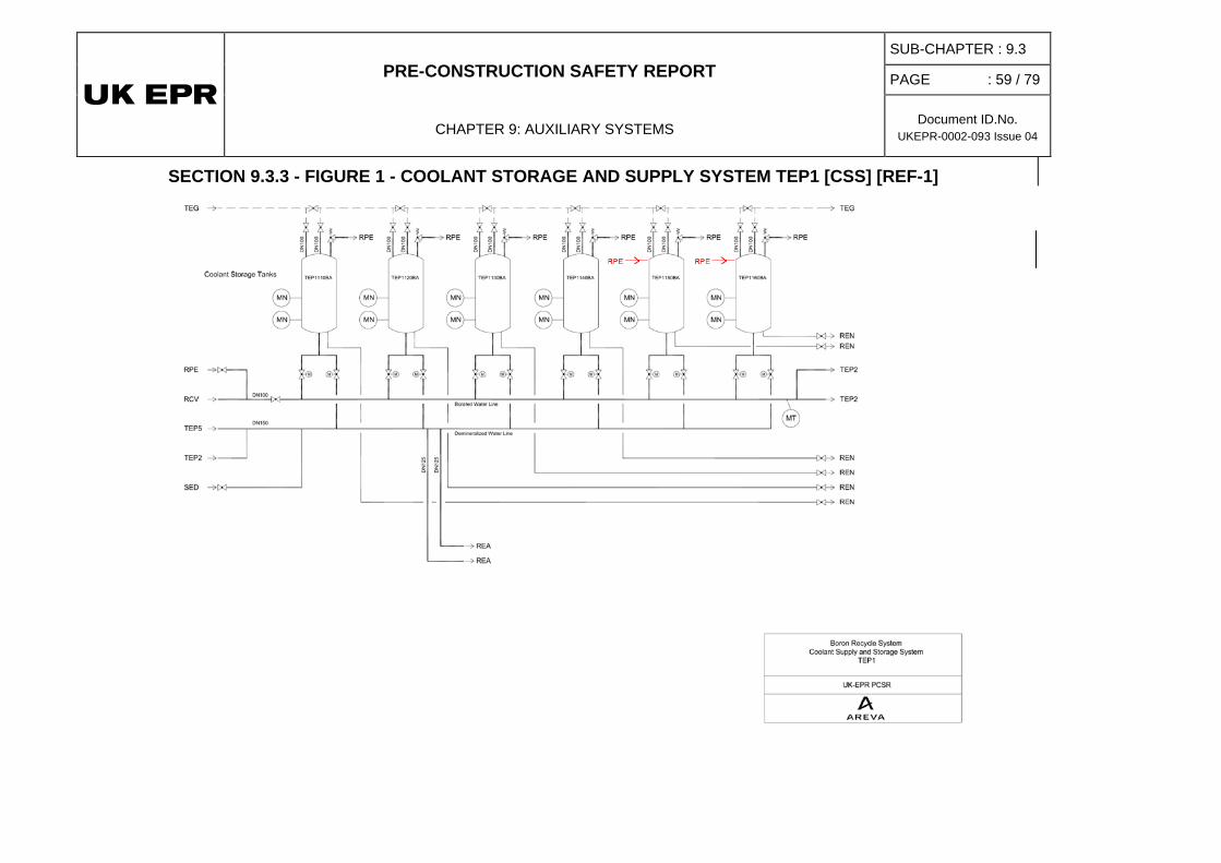
PRE-CONSTRUCTION SAFETY REPORT
CHAPTER 9: AUXILIARY SYSTEMS
SUB-CHAPTER : 9.3
PAGE : 59 / 79
Document ID.No. UKEPR-0002-093 Issue 04
SECTION 9.3.3 - FIGURE 1 - COOLANT STORAGE AND SUPPLY SYSTEM TEP1 [CSS] [REF-1]
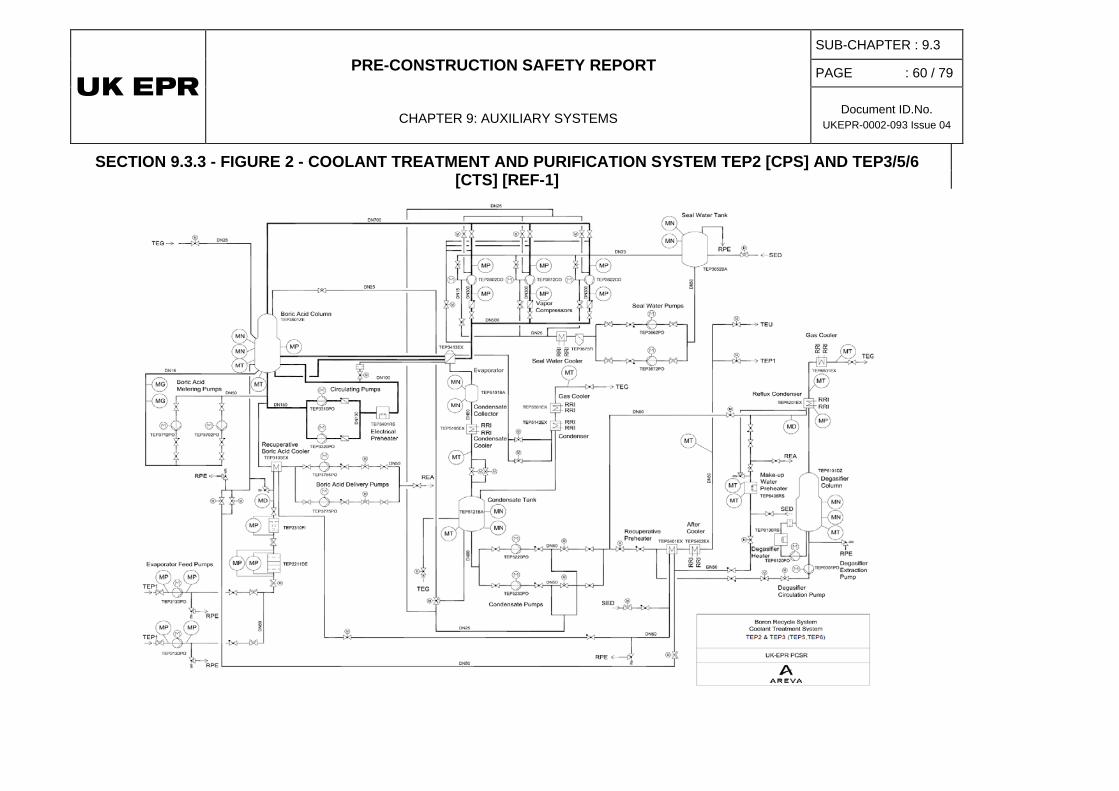
PRE-CONSTRUCTION SAFETY REPORT
CHAPTER 9: AUXILIARY SYSTEMS
SUB-CHAPTER : 9.3
PAGE : 60 / 79
Document ID.No. UKEPR-0002-093 Issue 04
SECTION 9.3.3 - FIGURE 2 - COOLANT TREATMENT AND PURIFICATION SYSTEM TEP2 [CPS] AND TEP3/5/6 [CTS] [REF-1]
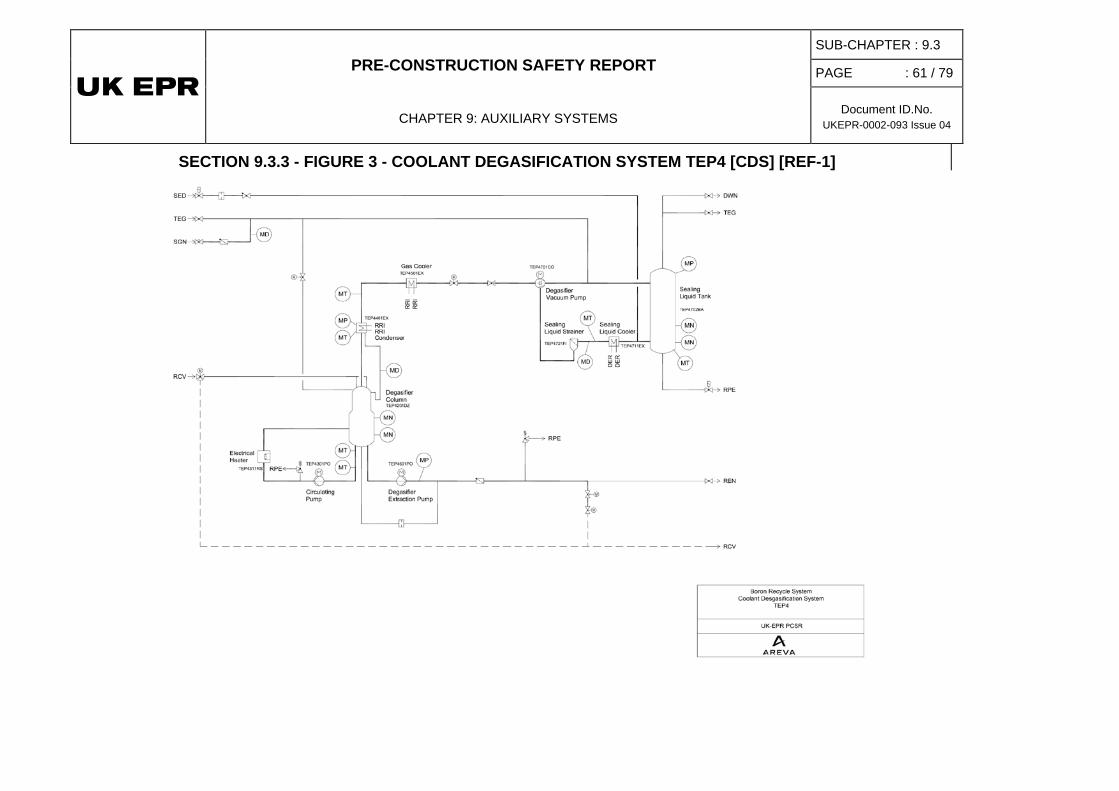
PRE-CONSTRUCTION SAFETY REPORT
CHAPTER 9: AUXILIARY SYSTEMS
SUB-CHAPTER : 9.3
PAGE : 61 / 79
Document ID.No. UKEPR-0002-093 Issue 04
SECTION 9.3.3 - FIGURE 3 - COOLANT DEGASIFICATION SYSTEM TEP4 [CDS] [REF-1]
PRE-CONSTRUCTION SAFETY REPORT
CHAPTER 9: AUXILIARY SYSTEMS
SUB-CHAPTER : 9.3
PAGE : 62 / 79
Document ID.No. UKEPR-0002-093 Issue 04
4. REACTOR BORON AND WATER MAKEUP SYSTEM
4.0. SAFETY REQUIREMENTS
4.0.1. Safety Function
4.0.1.1. Reactivity Control
During normal operation, the REA [RBWMS] system contributes to reactivity control by adjusting the reactor coolant system (RCP [RCS]) boron concentration, via the chemical and volume control system (RCV [CVCS]). This boron concentration adjustment is used for the purpose of controlling power changes (in conjunction with the control rods) during reactor start-up and shutdown, or offsetting fuel burnup.
4.0.1.2. Residual Heat Removal
The REA [RBWMS] is not involved in performing the safety function of residual heat removal.
4.0.1.3. Containment of Radioactive Substances
As the REA [RBWMS] is a system which contains radioactive products, its pressure boundary must act as a barrier to the transfer of radioactive material it contains or extracts during operation.
4.0.2. Functional Criteria
Since the REA [RBWMS] does not perform an active safety function, there are no safety-related functional criteria.
4.0.3. Design Requirements
4.0.3.1. Requirements from Safety Classification
The REA [RBWMS] safety classification must comply with the requirements stated in Sub-chapter 3.2.
• Single Failure Criterion (Active and Passive)
No safety requirement.
• Emergency Power Sources
No safety requirement.
• Qualification for Normal Operating Conditions
No safety requirement.
PRE-CONSTRUCTION SAFETY REPORT
CHAPTER 9: AUXILIARY SYSTEMS
SUB-CHAPTER : 9.3
PAGE : 63 / 79
Document ID.No. UKEPR-0002-093 Issue 04
• Mechanical, Electrical and Instrumentation and Control (I&C) classifications
Mechanical, electrical and I&C classification of the REA [RBWMS] must comply with the provisions of Sub-chapter 3.2.
• Seismic Classification
The REA [RBWMS] seismic classification must comply with the provisions of Sub-chapter 3.2.
4.0.3.2. Other Regulatory Requirements
• Regulatory Documents
No specific requirement.
• Basic Safety Rules
Application of basic safety rules must be compliant with the requirements stated in Sub-chapter 1.4. (There are no specific rules applicable to the REA [RBWMS]).
• Technical Guidelines
No specific requirement (see Sub-chapter 3.1).
• Regulatory Documents Specific to the EPR
Not applicable.
4.0.3.3. Hazards
• Internal Hazards
In accordance with Sub-chapter 13.2, there is no specific requirement for the REA [RBWMS] to be protected against internal hazards.
• External Hazards
In accordance with Sub-chapter 13.1, there is no specific requirement for the REA [RBWMS] to be protected against external hazards.
4.0.4. Testing
4.0.4.1. Preliminary Tests
Preliminary tests must demonstrate that REA [RBWMS] design ensures the required system performance, in conjunction with the RCV [CVCS] and the Reactor Control Surveillance and Limitation System (RCSL).
4.0.4.2. Periodic Tests and In-Service Inspection
Periodic testing is not required for the REA [RBWMS] system.
PRE-CONSTRUCTION SAFETY REPORT
CHAPTER 9: AUXILIARY SYSTEMS
SUB-CHAPTER : 9.3
PAGE : 64 / 79
Document ID.No. UKEPR-0002-093 Issue 04
4.1. FUNCTIONAL ROLE OF THE SYSTEM
In conjunction with the RCV [CVCS] or the RCSL, the REA [RBWMS] controls the boron concentration in the RCP [RCS] during normal operation. It also controls all anticipated reactivity changes, including those due to xenon effects.
When the reactor is at power, the quantity of boric acid stored in the REA [RBWMS] for injection to the RCP [RCS] via the RCV [CVCS] is adequate to return the core to a subcritical state in cold shutdown, independent of the increase in reactivity due to xenon decay.
The REA [RBWMS] also affords control, via the RCV [CVCS], of slow reactivity changes (including those due to xenon effects), through adjustment of RCP [RCS] boron concentration and thus follows anticipated load changes.
The REA [RBWMS] and the RCV [CVCS] are designed to mitigate or prevent the RCP [RCS] against undesired homogenous or heterogeneous boron dilution faults.
The REA [RBWMS] is also designed to perform the following main functions:
• regulate boric acid and/or degassed, demineralised water makeup to the RCP [RCS] via the RCV [CVCS], to control RCP [RCS] water inventory in the pressuriser (by the RCV [CVCS]) or to offset RCP [RCS] leakage during normal operation (via the RCV [CVCS]),
• prepare and distribute boric acid at a concentration of 4%,
• ensure filling of and boron makeup (4% boric acid) to both emergency boration system (RBS [EBS]) tanks,
• ensure filling of and boron makeup to the spent fuel pool and the IRWST via the fuel pool cooling system (PTR [FPCS]) with the correct concentration of boron.
4.2. APPLICABLE CRITERIA, DESIGN REQUIREMENTS AND CHARACTERISTICS [REF-1]
4.2.1. General Design Assumptions
In pressurised water reactors, boric acid (H3BO3) makeup or dilution of the reactor coolant is used to control slow reactivity changes.
When the boron concentration needs to be increased in the primary coolant, boric acid from the REA [RBWMS] is injected into the RCP [RCS] via the RCV [CVCS].
When boron concentration needs to be reduced in the primary coolant, demineralised water from the REA [RBWMS] is injected into the RCP [RCS] via the RCV [CVCS] (Suction of demineralised water injection pumps is taken from TEP [CSTS] in this case).
All other systems containing boric acid for reactivity control purposes are likewise supplied by the REA [RBWMS].
PRE-CONSTRUCTION SAFETY REPORT
CHAPTER 9: AUXILIARY SYSTEMS
SUB-CHAPTER : 9.3
PAGE : 65 / 79
Document ID.No. UKEPR-0002-093 Issue 04
4.2.1.1. System-Related Requirements
The system is designed to meet the following requirements:
• mixing and storing of 37 atomic percent enriched10B boric acid at a concentration of 4% (i.e. 7000 ppm of boron),
• supplying boric acid to the RBS [EBS] tanks at a concentration of 7000 ppm,
• preparing boric acid for use in filling the fuel pools and the IRWST (via the PTR [FPCS]) [The quantity required to fill the RIS [SIS] accumulators is injected from the IRWST. The boron concentration of the pools is selected in accordance with refueling requirements.]
• reducing primary coolant boron concentration during plant start-up,
• adjusting the primary coolant boron concentration to offset reactivity changes due to xenon poisoning, load follow, or fuel burnup,
• injecting boric acid and demineralised water at a ratio equivalent to the primary coolant boron concentration in order to make up primary coolant leakage during normal plant operation,
• increasing the primary coolant boron concentration during plant cooldown,
• borating the RCP [RCS] prior to opening the reactor pressure vessel for refueling, to reach a boron concentration that ensures subcriticality with all control rods out.
4.2.1.2. System Design
The boric acid storage capacity is determined by the maximum stored boric acid mass generated by all reactor coolant-containing systems that contribute to boron dilution due to fuel burnup over a cycle. These systems are the RCP [RCS] (including the pressuriser), the RCV [CVCS], the nuclear vent and drain system (RPE [NVDS]) and the coolant storage and treatment system (TEP [CSTS]).
The parameters listed below have an impact on the design of injection equipment, specifically the characteristics of the boric acid injection pump and the characteristics of the demineralised water pumps and associated control valves of the REA [RBWMS]:
• rod cluster control assembly (RCCA) control I&C functions,
• limiting conditions of operation (LCOs) for surveillance of control rod positions,
• RCCA protection I&C functions,
• level control of the volume control tank (VCT), compensating for any loss of RCP [RCS] inventory due to leakage,
• actual flow rates in the boric acid injection line and/or the demineralised water injection line to the RCV [CVCS].
PRE-CONSTRUCTION SAFETY REPORT
CHAPTER 9: AUXILIARY SYSTEMS
SUB-CHAPTER : 9.3
PAGE : 66 / 79
Document ID.No. UKEPR-0002-093 Issue 04
4.2.2. Other Requirements
4.2.2.1. Maximum Boron Concentration
The boric acid saturation concentration in the reactor coolant is temperature dependent. To avoid crystallisation, the temperature in the bunkers containing the boric acid (7000 ppm) must be kept above 20°C by the ventilation system.
To ensure availability, an emergency power supply must be provided for the ventilation system of these rooms in the event of a LOOP (loss of offsite power) – see Chapter 9.4.
4.2.2.2. Overpressure Protection
The boric acid tanks are designed for a pressure lower than the rest of the system because of their large size. A safety valve installed on the top of each storage tank protects against over-pressure. The capacity of the safety valves is based on the flow generated by the boric acid injection pump discharging from one boric acid storage tank into the other boric acid storage tank when isolated from the TEP [CSTS].
4.2.2.3. Emergency Power Sources
To ensure availability, an emergency power supply must be provided for REA [RBWMS] components involved in boric acid and demineralised water makeup, since the RCV [CVCS] is required in the event of a LOOP.
The control valves of the Reactor Boron and Water Make-up System are supplied by the uninterruptible nuclear island AC power supply. The agitator and the boric acid feed pump are powered by the normal nuclear island power supply. The boric acid pumps and the demineralized water pumps are supplied by the nuclear island emergency power supply.
4.3. SYSTEM DESCRIPTION - EQUIPMENT CHARACTERISTICS
4.3.1. System Description [Ref-1] to [Ref-6]
4.3.1.1. Mixing and Distribution of Boric Acid
The boric acid mixing and distribution part of the REA [RBWMS] consists of a boric acid mixing tank with an agitator, a boric acid feed pump, a filter upstream of the pump and the associated pipework.
The mixing tank is used to produce boric acid by dissolving "nuclear grade" boric acid powder in heated demineralised water to obtain a concentration of 4% H3BO3. This 4% concentration is used to fill the REA [RBWMS] boric acid storage tanks and the RBS [EBS] tanks. The RIS [SIS] accumulators, the RIS [SIS] itself, the IRWST, the RCP [RCS] and the fuel pools are initially filled with boric acid diluted to the concentration required for refueling. During normal plant operation, H3BO3 preparation is only intended to offset boric acid losses or to replace depleted boric acid.
PRE-CONSTRUCTION SAFETY REPORT
CHAPTER 9: AUXILIARY SYSTEMS
SUB-CHAPTER : 9.3
PAGE : 67 / 79
Document ID.No. UKEPR-0002-093 Issue 04
4.3.1.2. Boric Acid Storage and Injection Line
The requirement that tanks be accessible for inspection along with fuel building layout requirements means that boric acid storage capacity must be divided between two tanks. Once initial filling has taken place, 4% boric acid is provided by the evaporator column of the TEP [CSTS]. Two boric acid injection pumps, with downstream control valves, are installed to inject the required amount of boric acid into the RCP [RCS] via the RCV [CVCS].
4.3.1.3. Demineralised Water Injection Line
Effluent from the RCP [RCS] is treated by the TEP [CSTS] by separating the boric acid from the demineralised water. The resulting demineralised water is degassed and stored in the TEP [CSTS] tanks, one of which is always aligned to the demineralised water injection pumps. To ensure the necessary redundancy considering the small quantities of water involved, two 100% capacity pumps with downstream control valves are installed to inject the required amount of demineralised water into the RCV [CVCS]. As a provision against erroneous boron dilution, redundant control of the demineralised water injection is provided.
4.3.2. Major Equipment Characteristics
4.3.2.1. General Operating Data
Volume of the two boric acid storage tanks:
• approximately 104 m3 of total volume each,
• 92 m3 of usable volume each
Boric acid injection rate (flow rate of each injection line): 0.6 - 7 kg/s
Boric acid injection rate (nominal flow rate of each injection line): 6 kg/s
Demineralised water injection rate (flow rate of each injection line): 1.3 - 15 kg/s
Demineralised water injection rate (nominal flow rate of each injection line):13 kg/s
Usable volume of the boric acid mixing tank: 10 m³
4.3.2.2. Boric Acid
• Boron concentration: 7000 ppm minimum (4%)
• Hydrogen (H2) in the tanks < 2 ppm
4.3.2.3. Demineralised Water
• Boron concentration: < 5 ppm
A complete set of reactor coolant chemistry characteristics is given in Sub-chapter 5.5.
PRE-CONSTRUCTION SAFETY REPORT
CHAPTER 9: AUXILIARY SYSTEMS
SUB-CHAPTER : 9.3
PAGE : 68 / 79
Document ID.No. UKEPR-0002-093 Issue 04
4.3.3. Equipment Location
The REA [RBWMS] is installed in the fuel building. Only the demineralised water injection pumps and their pipework, valves, and measuring devices are located inside the nuclear auxiliary building.
4.3.4. Construction Requirements
To minimise leakage, in particular with regard to 10B and radioactive contamination, metal bellows sealed globe valves or equivalent are used.
4.3.4.1. Materials
All components are made of austenitic steel. Joints are welded except when flanged connections are used where maintenance or inspections make removal necessary.
4.3.4.2. Pumps
The pumps are of the direct driven fixed speed type. Because of leakage risk, pumps are of the canned rotor type.
4.3.4.3. Insulation
The lines used to fill the boric acid storage tanks may occasionally reach temperatures of more than 60°C due to exceptional TEP [CSTS] operation and therefore they are insulated.
No insulation is used in the rest of the system.
4.4. OPERATING CONDITIONS
The REA [RBWMS] is designed to operate only during normal plant operation, and performs the following functions:
• mixing and distribution of boric acid
• storage and injection of boric acid
• injection of demineralised water.
4.4.1. Mixing and Distribution of Boric Acid
Most of the boric acid is necessary during initial plant start-up for initial filling of the boric acid tanks, RBS [EBS] tanks, reactor coolant system, fuel pool, IRWST and all other systems and components containing boric acid solution. During normal plant operation, boric acid makeup is only necessary to offset normal losses.
PRE-CONSTRUCTION SAFETY REPORT
CHAPTER 9: AUXILIARY SYSTEMS
SUB-CHAPTER : 9.3
PAGE : 69 / 79
Document ID.No. UKEPR-0002-093 Issue 04
The boric acid mixing tank is used to prepare a boric acid solution by dissolving "nuclear-grade" boric acid powder in heated demineralised water to obtain a mixture containing 4% H3BO3. The agitator serves to dissolve the powder in the preheated water, thus producing a homogeneous solution. Once dissolved, the boric acid is distributed by starting up the boric acid feed pump. Boric acid at 4% is routed to the boric acid storage tanks and the two RBS [EBS] tanks. All other systems and components are filled with diluted boric acid. The required concentration is prepared by mixing the boric acid with demineralised water to obtain the required boric acid concentration.
The boric acid injection pump can also be used to mix the contents of the tank via the mixing line, to ensure a homogenous solution of boric acid inventory is maintained.
4.4.2. Boric Acid Storage and Injection
4.4.2.1. Boric Acid Storage
The boric acid storage tanks contain the entire operational mass of boric acid required for neutron-absorption during normal plant operation. During normal operation, the level in the tanks increases so that they are nearly full at the end of life.
The lowest level in the tanks is reached when the RCP [RCS] has the concentration required for refuelling and the pressuriser is full of liquid. At this point, fuel cycle status and 10B enrichment, the remaining boric acid capacity is sufficient for returning the plant to cold shutdown immediately following a startup to full power operation.
The boric acid storage tanks are initially filled with boric acid at 4% from the mixing and distribution part of the system. The two tanks are separated by motor operated valves. After initial filling, boric acid is recovered from the TEP [CSTS] evaporator, which enables separation of the coolant into boric acid at 4% and demineralised water.
4.4.2.2. Boric Acid Injection
Normally both boric acid pumps are connected to both boric acid storage tanks. If one pump is not working or fails to start, the other pump can be placed in service to supply boric acid to the RCP [RCS] via the RCV [CVCS]. A connection between the discharge of each pump and its assigned tank enables recirculation of the boric acid to ensure a homogenous solution and avoid crystallisation in the tank. During this operation, the other pump can be used to supply boric acid to the RCP [RCS].
A control valve located downstream of each pump regulates the flow into the RCV [CVCS].
4.4.3. Demineralised Water Injection
The REA [RBWMS] demineralised water subsystem consists of two parallel trains. Each train is equipped with an injection pump that takes suction from the TEP [CSTS] demineralised water line and a downstream control valve for injection of the required demineralised water flow rate to the RCV [CVCS].

PRE-CONSTRUCTION SAFETY REPORT
CHAPTER 9: AUXILIARY SYSTEMS
SUB-CHAPTER : 9.3
PAGE : 70 / 79
Document ID.No. UKEPR-0002-093 Issue 04
4.5. PRELIMINARY SAFETY ANALYSIS
4.5.1. Compliance with Regulations
The REA [RBWMS] complies with the applicable general regulations (see Sub-chapter 1.4).
4.5.2. Compliance with Functional Criteria
The REA [RBWMS] is not directly involved in performing the three basic safety functions. There are thus no safety-related functional criteria.
4.5.3. Compliance with Design Requirements
4.5.3.1. Safety Classification
Compliance of equipment design and construction with the safety classification rules is detailed in Sub-chapter 3.2.
4.5.3.2. Single Failure Criterion (Redundancy)
The single failure criterion does not apply to the REA [RBWMS].
4.5.3.3. Qualification to Operating Conditions
Not applicable.
4.5.3.4. Instrumentation and Control (I&C)
Compliance of equipment design and construction with the safety classification rules is detailed in Sub-chapter 3.2.
4.5.3.5. Emergency Power Supplies
Beside the provisions described in section 4.2.2.3, there are no safety requirements.
4.5.3.6. Hazards
Not applicable (see Chapter 13).
4.6. SPECIFIC TEST REQUIREMENTS
The REA [RBWMS] is designed for in-service inspection. It is a requirement that preventive maintenance operations must be possible during plant operation.
Since the REA [RBWMS] is used regularly in normal operation and performs no direct safety function, no periodic testing is required.
PRE-CONSTRUCTION SAFETY REPORT
CHAPTER 9: AUXILIARY SYSTEMS
SUB-CHAPTER : 9.3
PAGE : 71 / 79
Document ID.No. UKEPR-0002-093 Issue 04
4.7. SIMPLIFIED FLOW DIAGRAM
See Section 9.3.4 - Figure 1.
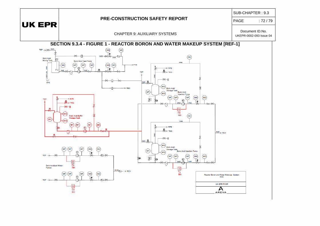
PRE-CONSTRUCTION SAFETY REPORT
CHAPTER 9: AUXILIARY SYSTEMS
SUB-CHAPTER : 9.3
PAGE : 72 / 79
Document ID.No. UKEPR-0002-093 Issue 04
SECTION 9.3.4 - FIGURE 1 - REACTOR BORON AND WATER MAKEUP SYSTEM [REF-1]
PRE-CONSTRUCTION SAFETY REPORT
CHAPTER 9: AUXILIARY SYSTEMS
SUB-CHAPTER : 9.3
PAGE : 73 / 79
Document ID.No. UKEPR-0002-093 Issue 04
SUB-CHAPTER 9.3 – REFERENCES
External references are identified within this sub-chapter by the text [Ref-1], [Ref-2], etc at the appropriate point within the sub-chapter. These references are listed here under the heading of the section or sub-section in which they are quoted.
1. NUCLEAR ISLAND SAMPLING SYSTEM
1.2. DESIGN BASIS
[Ref-1] System Design Manual – Nuclear Sampling System – Primary Side (REN [NSS]), Part 2 – System Operation (Stage 2). SFL-EZS-030035 Revision E. EDF. December 2008 (E)
[Ref-2] System Design Manual – Nuclear Sampling System (Inside RB) (REN [NSS]), Part 2 – System Operation (Stage 2). NESS-F DC 625 Revision A. AREVA. November 2009. (E)
[Ref-3] System Design Manual – Nuclear Sampling System – Primary Side (REN [NSS]), Part 3 – Sizing of the System and its Components (Stage 2). SFL-EZS-030036 Revision E. EDF. December 2008. (E)
[Ref-4] System Design Manual – Nuclear Sampling System (Inside RB) (REN [NSS]), Part 3 – System Design (Stage 2). NESS-F DC 626 Revision A. AREVA. November 2009. (E)
[Ref-5] System Design Manual – Nuclear Sampling System – Primary Side (REN [NSS]), Part 4 – Flow diagrams (Stage 2). SFL-EZS-030037 Revision F. EDF. December 2008. (E)
[Ref-6] System Design Manual – Nuclear Sampling System – Primary Side (REN [NSS]), Part 4.1 – Functional flow diagram. EZS/2006/en/0016 Revision B. EDF. October 2008. (E)
[Ref-7] System Design Manual – Nuclear Sampling System – Primary Side (REN [NSS]), Part 4.2 – Detailed flow diagram (Stage 2). EZS/2006/en/0018 Revision A. EDF. February 2007. (E)
[Ref-8] System Design Manual – Nuclear Sampling System (Inside RB) (REN [NSS]),Part 4 – Flow diagrams (Stage 2). NESS-F DC 627 Revision A. AREVA. November 2009. (E)
[Ref-9] System Design Manual – Nuclear Sampling System – Primary Side (REN [NSS]), Part 5 – I&C (Stage 2). EZS/2006/en/0003 Revision F. EDF. October 2008. (E)
[Ref-10] System Design Manual – Nuclear Sampling System - Secondary Side (RES [NSS]), Part 1 - History of the System Manual. SFL-EZS-030029 Revision C. Sofinel (EDF). April 2007. (E)
[Ref-11] System Design Manual – Nuclear Sampling System – Secondary Side (RES [NSS]), Part 2 – System Operation (Stage 2). SFL-EZS-030030 Revision C. EDF. April 2007. (E)
PRE-CONSTRUCTION SAFETY REPORT
CHAPTER 9: AUXILIARY SYSTEMS
SUB-CHAPTER : 9.3
PAGE : 74 / 79
Document ID.No. UKEPR-0002-093 Issue 04
[Ref-12] System Design Manual – Nuclear Sampling System – Secondary Side (RES [NSS]), Part 3 – Sizing of the System and its Components (Stage 2). SFL-EZS-030031 Revision C. EDF. April 2007. (E)
[Ref-13] System Design Manual – Nuclear Sampling System – Secondary Side (RES [NSS]), Part 4 – Flow diagrams (Stage 2). SFL-EZS-030032 Revision C. EDF. May 2007. (E)
[Ref-14] System Design Manual – Nuclear Sampling System – Secondary Side (RES [NSS]), Part 4.1 – Functional flow diagram. EZS/2006/en/0015 Revision B. EDF. July 2008. (E)
[Ref-15] System Design Manual – Nuclear Sampling System – Secondary Side (RES [NSS]), Part 4.2 – Detailed flow diagram. EZS/2006/en/0017 Revision A. EDF. February 2007. (E)
[Ref-16] System Design Manual – Nuclear Sampling System – Secondary Side (RES [NSS]), Part 5 – I&C (Stage 2). EZS/2006/en/0004 Revision C. EDF. June 2007. (E)
1.3. DESCRIPTION, CHARACTERISTICS OF EQUIPMENT
[Ref-1] System Design Manual – Nuclear Sampling System – Primary Side (REN [NSS]), Part 2 – System Operation (Stage 2). SFL-EZS-030035 Revision E. EDF. December 2008. (E)
[Ref-2] System Design Manual – Nuclear Sampling System (Inside RB) (REN [NSS]), Part 2 – System Operation (Stage 2). NESS-F DC 625 Revision A. AREVA. November 2009. (E)
[Ref-3] System Design Manual – Nuclear Sampling System – Primary Side (REN [NSS]), Part 3 – Sizing of the System and its Components (Stage 2). SFL-EZS-030036 Revision E. EDF. December 2008. (E)
[Ref-4] System Design Manual – Nuclear Sampling System (Inside RB) (REN [NSS]), Part 3 – System Design (Stage 2). NESS-F DC 626 Revision A. AREVA. November 2009. (E)
[Ref-5] System Design Manual – Nuclear Sampling System – Primary Side (REN [NSS]), Part 4 – Flow diagrams (Stage 2). SFL-EZS-030037 Revision F. EDF. December 2008. (E).
[Ref-6] System Design Manual – Nuclear Sampling System – Primary Side (REN [NSS]), Part 4.1 – Functional flow diagram. EZS/2006/en/0016 Revision B. EDF. October 2008. (E)
[Ref-7] System Design Manual – Nuclear Sampling System – Primary Side (REN [NSS]), Part 4.2 – Detailed flow diagram (Stage 2). EZS/2006/en/0018 Revision A. EDF. February 2007. (E)
[Ref-8] System Design Manual – Nuclear Sampling System (Inside RB) (REN [NSS]), Part 4 – Flow diagrams (Stage 2). NESS-F DC 627 Revision A. AREVA. November 2009. (E)
[Ref-9] System Design Manual – Nuclear Sampling System – Primary Side (REN [NSS]), Part 5 – I&C (Stage 2). EZS/2006/en/0003 Revision F. EDF. October 2008. (E)
PRE-CONSTRUCTION SAFETY REPORT
CHAPTER 9: AUXILIARY SYSTEMS
SUB-CHAPTER : 9.3
PAGE : 75 / 79
Document ID.No. UKEPR-0002-093 Issue 04
[Ref-10] System Design Manual – Nuclear Sampling System – Secondary Side (RES [NSS]), Part 2 – System Operation (Stage 2). SFL-EZS-030030 Revision C. EDF. April 2007. (E)
[Ref-11] System Design Manual – Nuclear Sampling System – Secondary Side (RES [NSS]), Part 3 – Sizing of the System and its Components (Stage 2). SFL-EZS-030031 Revision C. EDF. April 2007. (E)
[Ref-12] System Design Manual – Nuclear Sampling System – Secondary Side (RES [NSS]), Part 4 – Flow diagrams (Stage 2). SFL-EZS-030032 Revision C. EDF. May 2007. (E)
[Ref-13] System Design Manual – Nuclear Sampling System – Secondary Side (RES [NSS]), Part 4.1 – Functional flow diagram. EZS/2006/en/0015 Revision B. EDF. July 2008. (E)
[Ref-14] System Design Manual – Nuclear Sampling System – Secondary Side (RES [NSS]), Part 4.2 – Detailed flow diagram. EZS/2006/en/0017 Revision A. EDF. February 2007. (E)
[Ref-15] System Design Manual – Nuclear Sampling System – Secondary Side (RES [NSS]), Part 5 – I&C (Stage 2). EZS/2006/en/0004 Revision C. EDF. June 2007. (E)
1.4. OPERATING CONDITIONS
1.4.2. Permanent operating conditions
1.4.2.1. Primary sampling lines
[Ref-1] System Design Manual – Nuclear Sampling System – Primary Side (REN [NSS]), Part 2 – System Operation (Stage 2). SFL-EZS-030035 Revision E. EDF. December 2008. (E)
SECTION 9.3.1 - FIGURES 1 AND 2
[Ref-1] System Design Manual – Nuclear Sampling System – Primary Side (REN [NSS]), Part 2 – System Operation (Stage 2). SFL-EZS-030035 Revision E. EDF. December 2008. (E)
[Ref-2] System Design Manual – Nuclear Sampling System – Secondary Side (RES [NSS]), Part 2 – System Operation (Stage 2). SFL-EZS-030030 Revision C. EDF. April 2007. (E)
2. CHEMICAL AND VOLUME CONTROL SYSTEM
2.2. APPLICABLE CRITERIA, HYPOTHESES AND CHARACTERISTICS
[Ref-1] D Gschrey. Chemical and Volume Control System (RCV) P2 – Operation of the System. NGPS6/2006/en/1008 Revision G. AREVA. December 2008. (E)
PRE-CONSTRUCTION SAFETY REPORT
CHAPTER 9: AUXILIARY SYSTEMS
SUB-CHAPTER : 9.3
PAGE : 76 / 79
Document ID.No. UKEPR-0002-093 Issue 04
2.3. SYSTEM DESCRIPTION - EQUIPMENT CHARACTERISITICS
[Ref-1] D Gschrey. Chemical and Volume Control System (RCV) P2 – Operation of the System. NGPS6/2006/en/1008 Revision G. AREVA. December 2008. (E)
[Ref-2] M Bewer. Chemical and Volume Control System (RCV) P3 – System Sizing. NGPS6/2006/en/1018 Revision G. AREVA. December 2008. (E)
[Ref-3] M Bewer. Chemical and Volume Control System (RCV) P4 – Mechanical Diagrams (SMF and SMD). NGPS6/2006/en/1020 Revision H. AREVA. November 2008. (E)
[Ref-4] M Gaudiot. Chemical and Volume Control System (RCV) P5 – Instrumentation and Control. NESS-G/2006/en/1014 Revision F. AREVA. August 2008. (E)
2.3.1. System Description
2.3.1.1. Letdown
[Ref-1] D Gschrey. Chemical and Volume Control System (RCV) P2 – Operation of the System. NGPS6/2006/en/1008 Revision G. AREVA. December 2008. (E)
2.4. OPERATING CONDITIONS
2.4.4. Plant Startup
[Ref-1] D Gschrey. Chemical and Volume Control System (RCV) P2 – Operation of the System. NGPS6/2006/en/1008 Revision G. AREVA. December 2008. (E)
2.4.7. Reactor Cooldown
[Ref-1] D Gschrey. Chemical and Volume Control System (RCV) P2 – Operation of the System. NGPS6/2006/en/1008 Revision G. AREVA. December 2008. (E)
SECTION 9.3.2 - FIGURE 1
[Ref-1] M Bewer. System Design Manual – Chemical and Volume Control System (RCV [CVCS]), P4 – Mechanical Diagrams (SMF and SMD). NGPS6/2006/en/1020 Revision H. November 2008. (E)
PRE-CONSTRUCTION SAFETY REPORT
CHAPTER 9: AUXILIARY SYSTEMS
SUB-CHAPTER : 9.3
PAGE : 77 / 79
Document ID.No. UKEPR-0002-093 Issue 04
3. COOLANT PURIFICATION, DEGASIFICATION, STORAGE AND TREATMENT SYSTEM
3.2. DESIGN BASIS
[Ref-1] G Aranda. System Design Manual – Coolant Purification, Degasification, Storage and Treatment System (TEP [CSTS]) P2 –System Operation. SFL-EZS030008 Revision G. SOFINEL. October 2008. (E)
3.2.1. Coolant Storage and Treatment Systems
3.2.1.1. Coolant Storage and Supply System design
[Ref-1] G Aranda. System Design Manual – Coolant Purification, Degasification, Storage and Treatment System (TEP [CSTS]) P2 –System Operation. SFL-EZS030008 Revision G. SOFINEL. October 2008. (E)
3.2.1.2. Coolant Treatment System design
[Ref-1] G Aranda. System Design Manual – Coolant Purification, Degasification, Storage and Treatment System (TEP [CSTS]) P2 –System Operation. SFL-EZS030008 Revision G. SOFINEL. October 2008. (E)
3.2.3. Coolant Degasification
[Ref-1] R Hechame. System Design Manual – Coolant Purification, Degasification, Storage and Treatment System (TEP [CSTS]) P3 – Sizing of the system and its components. SFL-EZS030009 Revision F. SOFINEL. October 2008. (E)
3.3. EQUIPMENT DESCRIPTION AND CHARACTERISTICS
[Ref-1] G Aranda. System Design Manual – Coolant Purification, Degasification, Storage and Treatment System (TEP [CSTS]), P2 –System Operation, SFL-EZS-030008 Revision G. SOFINEL. October 2008. (E)
[Ref-2] R Hechame. System Design Manual – Coolant Purification, Degasification, Storage and Treatment System (TEP [CSTS]) P3 – Sizing of the system and its components. SFL-EZS030009 Revision F. SOFINEL. October 2008. (E)
[Ref-3] R Preiss. System Design Manual – Coolant Purification, Degasification, Storage and Treatment System (TEP [CSTS]) P4 – Flow diagrams. SFL-EZS030010 Revision E. SOFINEL. September 2008. (E)
[Ref-4] B Herve. System Design Manual – Coolant Purification, Degasification, Storage and Treatment System (TEP [CSTS]) P4.1 – Functional flow diagrams. EZS2006/en/0008 Revision A. SOFINEL. October 2006. (E)
[Ref-5] G Aranda. System Design Manual – Coolant Purification, Degasification, Storage and Treatment System (TEP [CSTS]) P4.2 – Detailed flow diagrams. EZS/2006/en/0009 Revision F. SOFINEL. October 2008. (E)
PRE-CONSTRUCTION SAFETY REPORT
CHAPTER 9: AUXILIARY SYSTEMS
SUB-CHAPTER : 9.3
PAGE : 78 / 79
Document ID.No. UKEPR-0002-093 Issue 04
[Ref-6] R Hechame. System Design Manual – Coolant Purification, Degasification, Storage and Treatment System (TEP [CSTS]) P5 – Instrumentation and control. SFL-EZS030077 Revision F. SOFINEL. November 2008. (E)
3.3.1. System description
[Ref-1] G Aranda. System Design Manual – Coolant Purification, Degasification, Storage and Treatment System (TEP [CSTS]) P2 –System Operation. SFL-EZS030008 Revision G. SOFINEL. October 2008. (E)
[Ref-2] R Hechame. System Design Manual – Coolant Purification, Degasification, Storage and Treatment System (TEP [CSTS]) P3 – Sizing of the system and its components. SFL-EZS030009 Revision F. SOFINEL. October 2008. (E)
SECTION 9.3.3 - FIGURES 1 TO 3
[Ref-1] G Aranda. System Design Manual – Coolant Purification, Degasification, Storage and Treatment System (TEP [CSTS]), P2 –System Operation. SFL-EZS-030008 Revision G. SOFINEL. October 2008. (E)
4. REACTOR BORON AND WATER MAKEUP SYSTEM
4.2. APPLICABLE CRITERIA, DESIGN REQUIREMENTS AND CHARACTERISTICS
[Ref-1] Muscetti R, Giraud A. Reactor Boron and Water Make-up System (REA) P2 – Operation of the System. SFL EF MF 2006.401 Revision E1. SOFINEL. September 2009. (E)
4.3. SYSTEM DESCRIPTION - EQUIPMENT CHARACTERISTICS
4.3.1. System Description
[Ref-1] Muscetti R, Giraud A. Reactor Boron and Water Make-up System (REA) P2 – Operation of the System. SFL EF MF 2006.401 Revision E1. SOFINEL. September 2009. (E)
[Ref-2] Muscetti R, Giraud A. Reactor Boron and Water Make-up System (REA) P3 – System sizing. EYTF/2007/fr/0041 Revision C1. EDF. September 2009. (E)
[Ref-3] Klinger J, Giraud A. Reactor Boron and Water Make-up System (REA) P4 – Mechanical Diagrams. SFL EF-MF-2006.225 Revision E1. SOFINEL. September 2009. (E)
PRE-CONSTRUCTION SAFETY REPORT
CHAPTER 9: AUXILIARY SYSTEMS
SUB-CHAPTER : 9.3
PAGE : 79 / 79
Document ID.No. UKEPR-0002-093 Issue 04
[Ref-4] Dossier de Système Elémentaire - Système d’appoint en eau et en bore (REA), P4.1 – Schémas Mécaniques Fonctionnel. [System Design Manual – Reactor Boron and Water Make-up System (REA) [RBWMS]), P4.1 – Functional flow diagram.] ECEF071383 Revision A. SOFINEL. March 2008.
[Ref-5] Dossier de Système Elémentaire - Système d’appoint en eau et en bore (REA), P4.2 – Schémas Mécaniques Détaillés. [System Design Manual – Reactor Boron and Water Make-Up System (REA [RBWMS]), P4.2 – Detailed Flow Diagrams.] EYTF-2006-FR-0002 Revision F. SOFINEL. December 2008.
[Ref-6] Klinger J, Giraud A. Reactor Boron and Water Make-up System (REA) P5 – Instrumentation and Control. SFL EF-MF-2006.593 Revision F1. SOFINEL. October 2008. (E)
SECTION 9.3.4 - FIGURE 1
[Ref-1] Dossier de Système Elémentaire - Système d’appoint en eau et en bore (REA), P4.2 – Schémas Mécaniques Détaillés. [System Design Manual – Reactor Boron and Water Make-Up System (REA [RBWMS]), P4.2 – Detailed Flow Diagrams.] EYTF-2006-FR-0002 Revision F. SOFINEL. December 2008.


![UKEPR-0002-092 Issue 04 - AREVA EDF - UK EPR™ … 9... · ESSENTIAL SERVICE WATER SYSTEM – SEC [ESWS] 1.0 ... [ESWS] indirectly contributes to maintain of the primary fluid inventory](https://img.pdfslide.net/doc/110x75/5b7f420e7f8b9a4c098bdb14/ukepr-0002-092-issue-04-areva-edf-uk-epr-9-essential-service-water.jpg)


![UKEPR-0002-095 Issue 04 9 - auxiliary... · The JDT [FDS] system is subjected to a test program after construction, and prior to fuel loading. 1.2.0.4.2. Monitoring during plant operation](https://img.pdfslide.net/doc/110x75/5fa022e014d23742e44440fd/ukepr-0002-095-issue-04-9-auxiliary-the-jdt-fds-system-is-subjected-to.jpg)