Embed Size (px)
Citation preview

ULNRC-05950 January 24, 2013 Enclosure 1 Page 1 of 12
CALLAWAY PLANT UNIT 1 LICENSE RENEWAL APPLICATION
REQUEST FOR ADDITIONAL INFORMATION (RAI) SET #19 AND SET #20 RESPONSES
REQUEST FOR ADDITIONAL INFORMATION (RAI) SET #19 RESPONSES

ULNRC-05950 January 24, 2013 Enclosure 1 Page 2 of 12
RAI B2.1.25-5b
Background:
A Close-Interval Survey and Direct Current Voltage Gradient Survey Buried Fire Water Protection Piping report, dated May 7, 2008, recommended that for locations not meeting the -850 mV criteria, the station should determine whether the alternative 100 mV potential shift criterion would demonstrate acceptable cathodic protection. The response to RAI B2.1.25-5a stated that corrosion coupons will be used to ensure that the cathodic protection system is providing sufficient protection for buried steel components within the scope of license renewal instead of using the 100 mV criterion.
Issue:
While the staff will consider using buried coupons to demonstrate the effectiveness of the cathodic protection system, the application lacks sufficient detail on what type of coupons will be used, how the corrosion coupons will be installed, the utilization of results, quantity of inspections that will occur while the level of protection is indeterminate, etc. In addition, no industry standards related to coupon testing were referenced (e.g., NACE Standard TM0169, ASTM G1, ASTM G16, ASTM G46).
Request:
Provide the following information:
a) Coupon Characteristics
• type of coupon to be used (e.g., free-corrosion coupon, polarized and native coupon pair, gravimetric, electrical resistance probe)
• whether the coupons will be coated with an intentionally embedded holiday (e.g., pitting rates would be expected to be higher at a holiday versus bare metal buried coupon) or will be bare metal and the surface condition (e.g., presence of scale and corrosion products, surface finish)
• composition of the coupon compared to the pipe (e.g., chemical composition and microstructure)
b) Coupon Placement
• how coupon locations will be selected so that they will be representative of the cathodic protection conditions at the point of interest? (i.e., not receiving preferential or diminished protection compared to the piping system of interest)
• how many coupons will be buried for each linear length of buried pipe?
• coupon size and orientation with respect to the pipe, for example, how close both in distance (e.g., no greater than a foot away from the pipe) and elevation (e.g., between bottom and up to one-third pipe diameter above bottom of pipe) the coupons will be installed to the pipe; and whether coupons will be perpendicular or parallel with the pipe?
• how long coupons will be allowed to be buried? (e.g., not to exceed seven years)
• how many years the coupons will be buried prior to accepting results?
ULNRC-05950 January 24, 2013 Enclosure 1 Page 3 of 12
• how for a given portion of pipe, how will the impact of localized soil parameters such as soil resistivity, soil chemistry, moisture content, temperature and microbiological activity be considered?
• how voids in the backfill will be avoided when installing coupons?
• how seasonal variability will be accounted for on soil characteristics? (e.g., cyclic wetting and drying can be more corrosive than soils that are constantly wet, diffusion of oxygen into the soil)
c) Analysis of Coupon Results
• what guidance will be used regarding coupon cleaning, corrosion rate calculations, and
data reporting?
• how pitting rates versus general corrosion rates will be differentiated?
d) Acceptance Criterion
• how the acceptance criterion for corrosion rates for general and pitting corrosion will be established?
e) Compensatory Excavated Direct Visual Inspections of In-Scope Buried Pipe
• how many inspections of buried pipe will occur during the time period when the
effectiveness is indeterminate? (i.e., it will take several years for the actual pitting or general corrosion to proceed beyond nominal thickness measurements of the coupon)
Callaway Response
Callaway is planning a modification to the cathodic protection system in 2015 with the intent of providing corrosion protection for buried steel piping, within the scope of license renewal, consistent with LR-ISG-2011-03. The response to RAI B2.1.25-5a stated that corrosion coupons will be used to ensure that the cathodic protection system is providing sufficient protection for buried steel components. While corrosion coupons may eventually be designed and installed, Callaway has deferred a decision on their usage to prove that portions of buried piping are effectively protected when the cathodic protection system is not meeting the installation, availability and effectiveness requirements of LR-ISG-2011-03 Table 4a Preventive Action C until after completion of the cathodic protection modification. For portions of buried piping within the scope of license renewal, in which the cathodic protection system is not meeting the LR-ISG-2011-03 Table 4a Preventive Action C requirements, LR-ISG-2011-03 Table 4a Category D, E or F inspection criteria will be used as applicable.
LRA Section B2.1.25, and LRA Section A1.25 have been revised as shown on LRA Amendment 20 in Enclosure 2 to remove reference to using corrosion coupons to ensure the effectiveness of the cathodic protection system.

ULNRC-05950 January 24, 2013 Enclosure 1 Page 4 of 12
Corresponding Amendment Changes
Refer to the Enclosure 2 Summary Table "Amendment 20, LRA Changes from RAI Responses and Commitment Updates,” for a description of LRA changes with this response.

ULNRC-05950 January 24, 2013 Enclosure 1 Page 5 of 12
RAI B2.1.25-6b
Background:
The response to RAI B2.1.25-6a stated that if the availability and effectiveness criteria in LR-ISG-2011-03 for portions of cathodically protected, in-scope pipe are not met, then the number of inspections corresponding to Preventive Action Category E would be conducted.
LR-ISG-2011-03, Table 4a, “Inspections of Buried Pipe,” states in part that “[s]oil testing should be conducted prior to submitting the application and once in each 10-year period starting 10 years prior to the period of extended operation.
Issue:
The staff does not agree that all of the conditions for the applicability of the Category E inspection quantities have been met. In that regard, Table 4a, footnote 2.E.ii.c., states that to use Category E, the soil must have been demonstrated to be not corrosive for the material type. Footnote 7 of this table provides the recommendations related to soil sampling. The staff recognizes that in its response to RAI B2.1.25-2 the applicant provided soil sample results for portions of buried stainless steel piping. Given the potential for variability in soil corrosivity, these sample results do not meet the intent of the recommendations in Footnote 7 for steel piping because no steel piping was buried in the vicinity of the samples. In addition, the staff recognizes that corrosion coupons will be used in areas where the cathodic protection system has been demonstrated to be ineffective; however, at this time, the staff does not believe that corrosion coupons can be substituted for soil sample results in regard to selection of the appropriate inspection category.
Request:
a) If available, provide soil sample results from the vicinity of buried in-scope steel piping sufficient to meet the recommendations of Footnote 7 of LR-ISG-2011-03 Table 4a.
b) If these results are not available, commit to completing the soil sampling during the 10-year period prior to the period of extended operation and in each subsequent 10-year period of extended operation and based upon the results, select the appropriate inspection category. Alternatively, or if the soil is demonstrated to be corrosive, revise the Buried and Underground Piping and Tanks Program to ensure that the number of buried pipe inspections will meet Category F in the 10-year period prior to the period of extended operation and in each subsequent 10-year interval for those portions of buried in-scope steel piping where the cathodic protection system does not meet the availability and effectiveness criteria for LR-ISG-2011-03.
c) Revise the FSAR supplement to reflect the need to conduct soil sampling in each 10-year period starting 10 years prior to the period of extended operation for portions of buried in-scope steel piping where the cathodic protection system does not meet the availability and effectiveness criteria of LR-ISG-2011-03 if the inspection quantities of Category E will be used.
ULNRC-05950 January 24, 2013 Enclosure 1 Page 6 of 12
Callaway Response
a) Soil sample results from the vicinity of buried in-scope steel piping are not available at the current time.
b) Callaway will perform soil sampling in the vicinity of buried in-scope steel piping in which the cathodic protection system does not meet the availability or effectiveness requirements specified in LR-ISG-2011-03. These soil samples will be conducted during the 10-year period prior to the period of extended operation and in each subsequent 10-year period during the period of extended operation. These samples will be obtained and tested consistent with the requirements specified in LR-ISG-2011-03, Table 4a, Footnote 7. If the soil is demonstrated not to be corrosive to buried steel piping, the number of inspections will be based on LR-ISG-2011-03, Table 4a Category E. If the soil is determined to be corrosive to buried steel piping, then the number of inspections will be based on LR-ISG-2011-03, Table 4a Category F. LRA Section B2.1.25, the Buried and Underground Piping and Tanks Program, has been revised as shown on LRA Amendment 20 in Enclosure 2 to indicate the requirements for performing soil samples and to do the required number of inspections based on the soil testing results in the vicinity of in-scope steel piping consistent with LR-ISG-2011-03 Table 4a.
c) The FSAR supplement has been revised to reflect the need to conduct soil sampling in each 10-year period starting 10 years prior to the period of extended operation and in each subsequent 10-year period during the period of extended operation for those areas of buried in-scope steel piping in which the cathodic protection system does not meet the availability or effectiveness requirements of LR-ISG-2011-03 Table 4a. LRA Section A1.25 has been revised as shown on LRA Amendment 20 in Enclosure 2 to reflect the need to perform soil sampling.
Corresponding Amendment Changes
Refer to the Enclosure 2 Summary Table "Amendment 20, LRA Changes from RAI Responses and Commitment Updates,” for a description of LRA changes with this response.

ULNRC-05950 January 24, 2013 Enclosure 1 Page 7 of 12
RAI B2.1.6-4a
Background:
Ameren (the applicant) provides its final safety analysis report (FSAR) supplement summary description for license renewal application (LRA) AMP B2.1.6, “PWR Vessel Internals,” in LRA Appendix A (LRA FSAR Supplement) section A1.6, “PWR Vessel Internals.” In this FSAR Supplement, the applicant states, in part, that “industry and plant-specific operating experience will be evaluated in the development and implementation of this program.” LRA FSAR Supplement Table A4-1 includes LRA Commitment No. 4, in which the applicant commits to implement the PWR Vessel Internals Program within two (2) years of the date of issuance of Electric Power Research institute (EPRI) Materials Reliability Program (MRP) Technical Report No. 1022863, “Materials Reliability Program: Pressurized Water Reactor Internals Inspection and Evaluation Guidelines (MRP-227-A).” MRP-227-A was issued by the EPRI MRP by letter dated January 9, 2012. On October 24, 2012, the applicant submitted its response to RAI Set 12. In this letter, the applicant responded to RAI B2.1.6-4, in which the applicant addressed plans for submitting a reactor vessel internal (RVI) inspection plan to the staff for review and for resolving the staff’s applicant/licensee action items (A/LAIs) that were issued on the MRP-227-A report. These A/LAIs were identified in the staff’s revised safety evaluation (SE) Revision 1 on the MRP-227-A report methodology, which was issued to the EPRI MRP by letter dated December 6, 2011. As part of its review of the A/LAI response summaries that were provided in the letter dated October 24, 2012, the staff was able to resolve all of Ameren’s A/LAI response bases within the exception of the response bases to A/LAIs #1, #5, and #8, Item 5.
Issue, Part 1:
In the response to RAI B2.1.6-4, the applicant states, in part:
Callaway will provide specific responses to the Applicant/Licensee Action Items (A/LAIs) identified in the December 16, 2011 staff Safety Evaluation on the MRP-227-A methodology in LRA Appendix C. The LRA Appendix C supplement for the staff safety Evaluation A/LAIs will be provided consistent with the LRA Table A4-1 item #4 commitment to implement the PWR Vessel Internals program as described in LRA Section B2.1.6 within 24 months after the issuance of MRP-227-A. LRA Table A4-1 item #4 also includes the Callaway reactor vessel internals inspection plan noted in part (b) of A/LAI item 8 of the staff Safety Evaluation on the MRP-227-A methodology. The Callaway reactor vessel internals inspection plan will be provided within 24 months after the issuance of MRP-227-A.
On the basis, the staff finds that the applicant needs to provide A/LAI responses to those A/LAIs that were not resolved as part of the staff’s review of the A/LAI summary response bases that were included in the response to RAI B2.1.6-4. However, the current version of LRA Commitment No. 4 does not include any provisions that the applicant will be submitting the Callaway RVI component inspection plan for staff review and approval by January 9, 2014, which is two years from the date of issuance of the staff-endorsed MRP-227-A report. Nor does LRA Commitment No. 4 include any provisions that the submittal of the RVI component inspection plan will specifically address those matters that were left as unresolved in the applicant’s A/LAI response summary bases to A/LAIs #1, #5, and #8, Item 5. These matters are:
• A/LAI #1 – Addressing: (a) whether the actual design stress values, temperature values, and neutron fluence values for the Callaway RVI components are bounded by the upper

ULNRC-05950 January 24, 2013 Enclosure 1 Page 8 of 12
bound values assumed for these components in the MRP-191 report; and (b) justifying why the program is considered to be adequate or clarifying and justifying how the program will need to be appropriately adjusted if it is determined that the actual design stress values, temperature values, and neutron fluence values for the Callaway RVI components are not bounded by the corresponding values assumed for these components in the MRP-191 report.
• A/LAI #5 – Defining and justifying: (a) the physical measure techniques that will be used to determine RVI hold-down spring height when physical measurements are performed on the component in accordance with the MRP-227-A methodology basis; (b) the analysis basis that will be used to project hold-down spring height through 60 years of licensed operations; and the acceptance criteria that will be used to evaluate RVI hold-down spring height that is projected at 60 years of licensed operation.
• A/LAI #8, Item 5 – For those RVI components that are defined as American Society of Mechanical Engineers (ASME) Section III, Subsection NG core support structure components and that have been analyzed in accordance with an ASME Section III, Subsection NG required fatigue analysis, clarifying and justifying how the impacts of the reactor coolant environment on the cumulative usage factor (CUF) values for the components will be addressed, or else how cumulative fatigue damage will be managed in a manner that resolves these impacts.
Request Part 1:
Provide your basis and justify why LRA Commitment No. 4 does not include commitment provisions that address the applicant’s intent to submit an RVI inspection plan for staff review and approval and the A/LAI matters summarized in the Issue Section of this part of RAI; otherwise, the staff request that Commitment No. 4 be amended to include these commitment provisions. If the applicant’s conclusion is that the LRA does not need to include a commitment on submittal of a RVI component inspection plan, provide your response to the three A/LAIs mentioned above.
Callaway Response
Callaway is considered a Category D plant consistent with Regulatory Issue Summary 2011-07 guidance because Callaway submitted their License Renewal Application based on GALL Revision 2. Callaway has submitted a PWR Vessel Internal program (NUREG-1801, XI.M16A) and associated license renewal documentation that is consistent with GALL Revision 2 as updated by applicable requirements of the NRC MRP-227-A Safety Evaluation dated December 16, 2011. Therefore Callaway will not be submitting a reactor vessel internal (RVI) component inspection plan as noted in our previous RAI response. In addition the following responses are provided for the following three referenced Applicant/Licensee Action Items of NRC MRP-227-A Safety Evaluation dated December 16, 2011.
A/LAI #1 – Comparison to Callaway RVI Components to MRP-191 Bounding Values
LRA Table A4-1 item 4 has been revised as shown on LRA Amendment 20 in Enclosure 2 to include resolution of A/LAI #1 as part of the implementation of the Reactor Vessel Internal program. The following will be addressed:

ULNRC-05950 January 24, 2013 Enclosure 1 Page 9 of 12
Each applicant/licensee is responsible for assessing its plant’s design and operating history and demonstrating that the approved version of MRP-227 is applicable to the facility. Each applicant/licensee shall refer, in particular, to the assumptions regarding plant design and operating history made in the FMECA and functionality analyses for reactors of their design (i.e., Westinghouse, CE, or B&W) which support MRP-227 and describe the process used for determining plant-specific differences in the design of their RVI components or plant operating conditions, which result in different component inspection categories. The applicant/licensee shall submit this evaluation for NRC review and approval as part of its application to implement the approved version of MRP-227.
A/LAI #5 – RVI Hold-Down Spring Measurements
The Callaway RVI hold-down spring is fabricated with type 403 stainless steel. As noted in NRC MRP-227-A Final Safety Evaluation dated December 16, 2011, section 3.3.5 physical measurements are utilized to monitor for loss of compressibility for Westinghouse hold down springs. As noted in section 3.3.5, MRP response to NRC 3-12 states that physical measurements specifically apply to type 304 stainless steel hold-down springs in Westinghouse designed plants. Therefore this A/LAI is not applicable to Callaway.
A/LAI #8 item #5 – Impact of the Reactor Coolant Environment on Cumulative Usage Factor
LRA Table A4-1 item 4 has been revised as shown on LRA Amendment 20 in Enclosure 2 to include resolution of reactor coolant system water environment portion of A/LAI #8 item #5 as part of the implementation of the Reactor Vessel Internal program. The reactor coolant system water environment portion of the following will be addressed:
For those cumulative usage factor (CUF) analyses that are TLAAs, the applicant may use the PWR Vessel Internals Program as the basis for accepting these CUF analyses in accordance with 10 CFR 54.21(c)(1)(iii) only if the RVI components in the CUF analyses are periodically inspected for fatigue-induced cracking in the components during the period of extended operation. The periodicity of the inspections of these components shall be justified to be adequate to resolve the TLAA. Otherwise, acceptance of these TLAAs shall be done in accordance with either 10 CFR 54.21(c)(1)(i) or (ii), or in accordance with 10 CFR 54.21(c)(1)(iii) using the applicant’s program that corresponds to NUREG-1801, Revision 2, AMP X.M1, “Metal Fatigue of Reactor Coolant Pressure Boundary Program.” To satisfy the evaluation requirements of ASME Code, Section III, Subsection NG-2160 and NG-3121, the existing fatigue CUF analyses should include the effects of the reactor coolant system water environment.
Corresponding Amendment Changes
Refer to the Enclosure 2 Summary Table "Amendment 20, LRA Changes from RAI Responses and Commitment Updates,” for a description of LRA changes with this response.

ULNRC-05950 January 24, 2013 Enclosure 1 Page 10 of 12
CALLAWAY PLANT UNIT 1 LICENSE RENEWAL APPLICATION
REQUEST FOR ADDITIONAL INFORMATION (RAI) SET #19 AND SET #20 RESPONSES
REQUEST FOR ADDITIONAL INFORMATION (RAI) SET #20 RESPONSE

ULNRC-05950 January 24, 2013 Enclosure 1 Page 11 of 12
RAI B2.1.14-5b
Background:
The staff reviewed the applicant’s response to request for additional information (RAI) B2.1.14-5a and has questions related to flow testing of the fire water system. In addition, while credited in the RAI response, trending of the microbiologically influenced corrosion (MIC) Index was not incorporated into the Fire Water System Program.
As described in the RAI response, the staff understands the following in relation to fire water system flow testing:
• Failure of the flow test in 2004 was attributed to accumulated corrosion products. The corrective action was to conduct chemical cleaning in 2006 and the subsequent flow test met acceptance criteria.
• Failure of the flow test in 2009 was attributed to a combination of factors related to the test procedure and calculation such as gauge elevation, rounding error, and rerouting of fire piping. Upon revision of the calculation and flow test procedure, the flow test met acceptance criteria.
• Failure of the flow test in 2011 was attributed to unnecessary conservatisms in the flow calculation such as how much additional flow was assumed to hose stations and yard hydrants coincident with sprinkler demand as compared to the licensing basis value. Additionally, the calculation used to determine pipe wall cleanliness was rewritten, including taking credit for actual fire pump performance. Upon revision of the calculations, the flow test met acceptance criteria.
Issue:
a) Although contributing factors to the flow test failures have been identified and the procedure used to verify operability has been revised, the test results indicate that the condition of the fire main is degrading. Specifically, the 2006 flow test was passed without the changes to the test procedures and calculations which were implemented to pass the 2009 and 2011 test results. Likewise, the 2009 flow test passed without the changes to the calculations which were implemented to pass the 2011 test results. Additionally, some of the procedure changes removed margin instead of correcting test process inaccuracies.
The proposed change to the program, including continued chemical additions to the fire water system to mitigate biological growth and augmented wall thickness inspections, do not resolve the staff’s concern related to the flow degradation in the system.
The response to RAI B2.1.14-5a, part (c) states that the program collects MIC samples and trends the MIC Index to evaluate treatment effectiveness in specific locations. However, although the amended Fire Water System Program discusses MIC sampling, it does not include MIC Index trending.
Request:
a) In light of the decreasing trend in system performance, state the basis for why flow testing of the system every 3 years will be sufficient to ensure that the system can perform its intended function during the period of extended operation.
b) Revise LRA Section B2.1.14 to include MIC Index trending.

ULNRC-05950 January 24, 2013 Enclosure 1 Page 12 of 12
Callaway Response
a) Callaway FSAR-SP Table 9.5.1-2 (Sheet 2) states that a flow test of the fire water system is to be performed at least once per 3 years to validate that an operable flow path exists. Until recently, this requirement was met by performing a Fire Main Flow Test with an assigned frequency of 36 months (3 years). Due to changes made to the flow test procedure and acceptance criteria, performance trending of data from the 2006, 2009, and 2011 flow tests does not provide a reliable long term prediction. Therefore, in January 2013, the frequency of the flow test was changed to perform the test every 24 months (2 years). Callaway has adopted this more conservative test frequency to increase the rate at which data can be gathered and to facilitate establishing a performance trend based on the current flow test procedures and acceptance criteria.
Test results of the Fire Main Flow Test are trended to ensure that adequate margin, including anticipated degradation and corrective action, exists through the next flow test interval to prevent failure of future flow tests. If a test yields results that do not meet the acceptance criteria established in the test procedure, it is documented in the corrective action program so that appropriate corrective actions can be developed to restore margin. The responsible engineer also reviews the adequacy of the frequency and scope of the flow test activity. Consequently, if a stable trend is established such that there is reasonable assurance that acceptable flow test results will be obtained if the flow test were conducted in 36 months, it may be justified to extend the performance frequency of the Fire Main Flow Test up to its original 36 month frequency. This justification may be based on factors including available margin or maintenance activities such as pipe cleaning, refurbishment or replacement.
The next Fire Main Flow Test is scheduled to be performed in 2013. Taking into account the 25% grace period that is procedurally allowed, the new 24-month frequency means that the Fire Main Flow Test will be performed at least four (4) and up to eight (8) times before the Period of Extended Operation (PEO).
b) LRA Section B2.1.14 and LRA Section A1.14 have been revised as shown on Amendment 20 in Enclosure 2 to include MIC Index trending.
Corresponding Amendment Changes
Refer to the Enclosure 2 Summary Table "Amendment 20, LRA Changes from RAI Responses and Commitment Updates,” for a description of LRA changes with this response.

ULNRC-05950 January 24, 2013 Enclosure 2 Page 1 of 23
Amendment 20, LRA Changes from RAI Responses and Commitment Updates
Enclosure 2 Summary Table
Affected LRA Section LRA Page
Section A1.14 A-8 Section A1.25 A-13 Table A4-1, item 4 A-37 Table A4-1, item 12 A-39 and A-40 Table A4-1, item 23 A-43 Section B2.1.14 B-53, B-54, B-55, B-56 and B-57 Section B2.1.25 B-87, B-88, B-89, and B-90 Section B2.1.27 B-94, B-95, and B-96 Section B2.1.31 B-104, B-105, B-106, and B-107

ULNRC-05950 January 24, 2013 Enclosure 2 Page 2 of 23
Callaway Plant Unit 1 Page A-8 License Renewal Application Amendment 20
Appendix A Final Safety Analysis Report Supplement
A1.14 FIRE WATER SYSTEM
The Fire Water System program manages loss of material for water-based fire protection systems. Consistent with National Fire Protection Association (NFPA) commitments, the program consists of periodic full-flow flush tests and system performance tests to prevent corrosion from biofouling in the fire protection system. The fire protection system is normally maintained at required operating pressure and is monitored such that loss of system pressure is immediately detected and corrective actions initiated.
The Fire Water System program conducts flow tests through each open head spray/sprinkler nozzle to verify water flow is unobstructed. Prior to 50 years in service, the Fire Water System program requires sprinkler heads to be replaced or have representative samples submitted for field-service testing by a recognized testing laboratory in accordance with NFPA 25. The program field-service tests additional representative samples every 10 years thereafter during the period of extended operation to ensure signs of aging are detected in a timely manner.
Non-intrusive wall thickness examinations are performed on fire water piping to identify loss of material. Wall thickness examinations will be performed on fire water piping every three years. Each three year sample will include at least three locations for a total of 100 feet of above-ground fire water piping and be selected based on system susceptibility to corrosion or fouling and evidence of performance degradation during system flow testing or periodic flushes. The basis for the frequency is that three years is the frequency required by the FSAR for the yard fire loop flush and for the flow tests of the fire water loops. In addition, visual internal inspections are used when the internal surface of the piping is exposed during plant maintenance. These inspections evaluate (a) wall thickness to ensure against catastrophic failure and (b) the inner diameter of the piping as it applies to the design flow of the fire protection system.
Samples are collected for microbiologically-influenced corrosion quarterly and when fire water piping and components are opened for maintenance or are accessible. Biofouling is prevented by periodically adding treatment chemicals such as an anti-scalant, a biopenetrant, and a biostat to the fire water system annually and when monitoring indicates they should be added. The MIC Index is trended to evaluate treatment effectiveness in specific locations.
The internal coating of the fire water storage tanks will be inspected with a minimum frequency of alternating refueling outages.
ULNRC-05950 January 24, 2013 Enclosure 2 Page 3 of 23
Callaway Plant Unit 1 Page A-13 License Renewal Application Amendment 20
Appendix A Final Safety Analysis Report Supplement
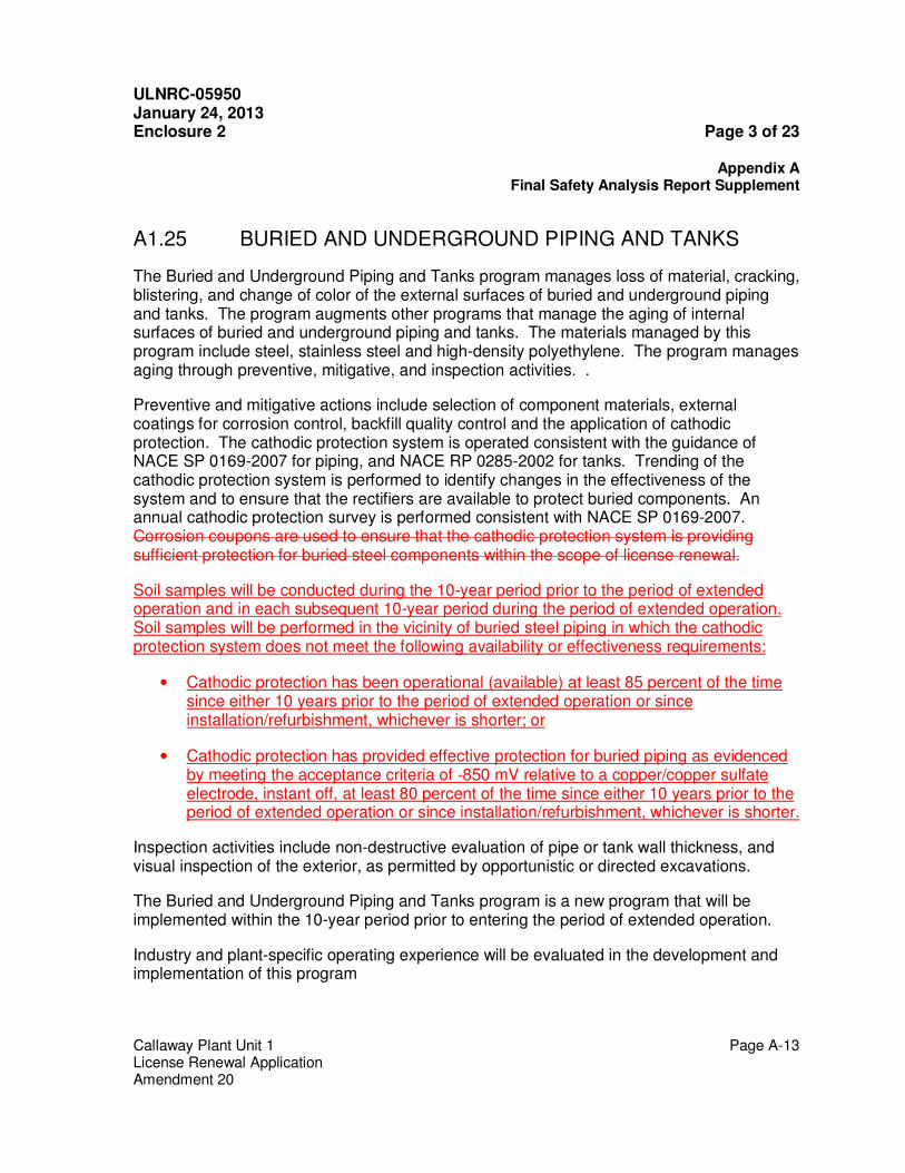
A1.25 BURIED AND UNDERGROUND PIPING AND TANKS
The Buried and Underground Piping and Tanks program manages loss of material, cracking, blistering, and change of color of the external surfaces of buried and underground piping and tanks. The program augments other programs that manage the aging of internal surfaces of buried and underground piping and tanks. The materials managed by this program include steel, stainless steel and high-density polyethylene. The program manages aging through preventive, mitigative, and inspection activities. .
Preventive and mitigative actions include selection of component materials, external coatings for corrosion control, backfill quality control and the application of cathodic protection. The cathodic protection system is operated consistent with the guidance of NACE SP 0169-2007 for piping, and NACE RP 0285-2002 for tanks. Trending of the cathodic protection system is performed to identify changes in the effectiveness of the system and to ensure that the rectifiers are available to protect buried components. An annual cathodic protection survey is performed consistent with NACE SP 0169-2007. Corrosion coupons are used to ensure that the cathodic protection system is providing sufficient protection for buried steel components within the scope of license renewal.
Soil samples will be conducted during the 10-year period prior to the period of extended operation and in each subsequent 10-year period during the period of extended operation. Soil samples will be performed in the vicinity of buried steel piping in which the cathodic protection system does not meet the following availability or effectiveness requirements:
• Cathodic protection has been operational (available) at least 85 percent of the time since either 10 years prior to the period of extended operation or since installation/refurbishment, whichever is shorter; or
• Cathodic protection has provided effective protection for buried piping as evidenced by meeting the acceptance criteria of -850 mV relative to a copper/copper sulfate electrode, instant off, at least 80 percent of the time since either 10 years prior to the period of extended operation or since installation/refurbishment, whichever is shorter.
Inspection activities include non-destructive evaluation of pipe or tank wall thickness, and visual inspection of the exterior, as permitted by opportunistic or directed excavations.
The Buried and Underground Piping and Tanks program is a new program that will be implemented within the 10-year period prior to entering the period of extended operation.
Industry and plant-specific operating experience will be evaluated in the development and implementation of this program
ULNRC-05950 January 24, 2013 Enclosure 2 Page 4 of 23
Callaway Plant Unit 1 Page A-37 License Renewal Application Amendment 20
Table A4-1 License Renewal Commitments Item # Commitment LRA
Section Implementation
Schedule
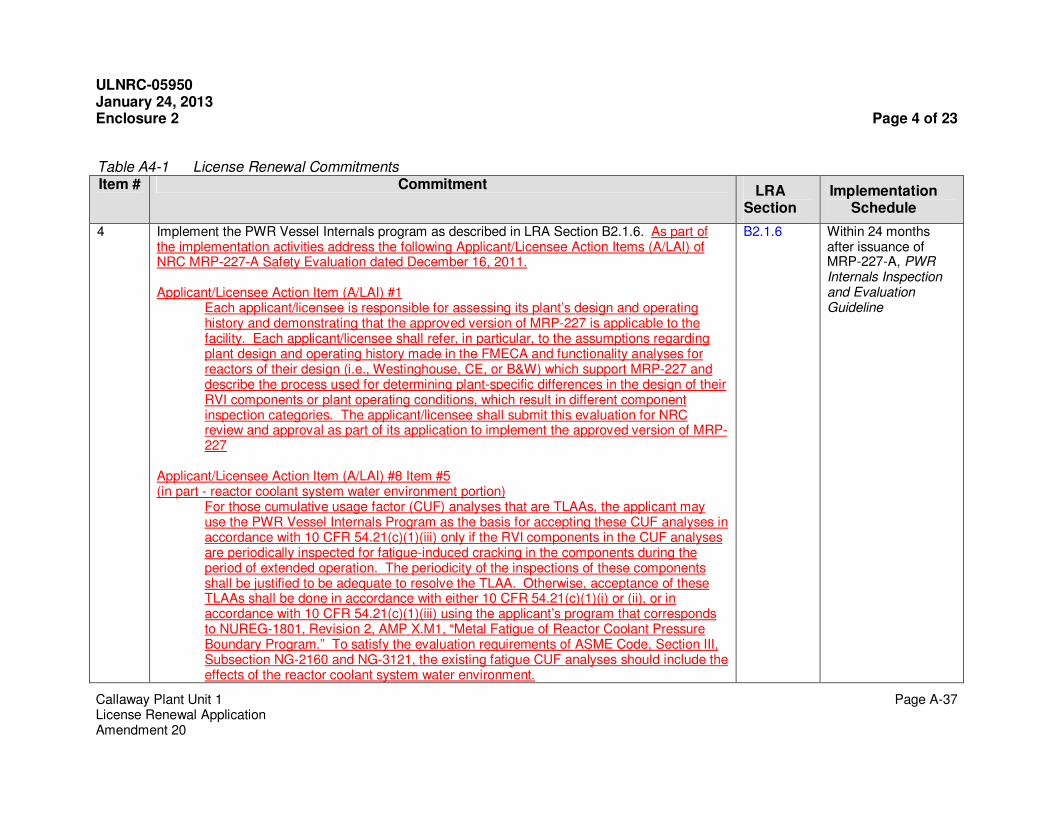
4 Implement the PWR Vessel Internals program as described in LRA Section B2.1.6. As part of the implementation activities address the following Applicant/Licensee Action Items (A/LAI) of NRC MRP-227-A Safety Evaluation dated December 16, 2011. Applicant/Licensee Action Item (A/LAI) #1
Each applicant/licensee is responsible for assessing its plant’s design and operating history and demonstrating that the approved version of MRP-227 is applicable to the facility. Each applicant/licensee shall refer, in particular, to the assumptions regarding plant design and operating history made in the FMECA and functionality analyses for reactors of their design (i.e., Westinghouse, CE, or B&W) which support MRP-227 and describe the process used for determining plant-specific differences in the design of their RVI components or plant operating conditions, which result in different component inspection categories. The applicant/licensee shall submit this evaluation for NRC review and approval as part of its application to implement the approved version of MRP-227
Applicant/Licensee Action Item (A/LAI) #8 Item #5 (in part - reactor coolant system water environment portion)
For those cumulative usage factor (CUF) analyses that are TLAAs, the applicant may use the PWR Vessel Internals Program as the basis for accepting these CUF analyses in accordance with 10 CFR 54.21(c)(1)(iii) only if the RVI components in the CUF analyses are periodically inspected for fatigue-induced cracking in the components during the period of extended operation. The periodicity of the inspections of these components shall be justified to be adequate to resolve the TLAA. Otherwise, acceptance of these TLAAs shall be done in accordance with either 10 CFR 54.21(c)(1)(i) or (ii), or in accordance with 10 CFR 54.21(c)(1)(iii) using the applicant’s program that corresponds to NUREG-1801, Revision 2, AMP X.M1, “Metal Fatigue of Reactor Coolant Pressure Boundary Program.” To satisfy the evaluation requirements of ASME Code, Section III, Subsection NG-2160 and NG-3121, the existing fatigue CUF analyses should include the effects of the reactor coolant system water environment.
B2.1.6 Within 24 months after issuance of MRP-227-A, PWR Internals Inspection and Evaluation Guideline

ULNRC-05950 January 24, 2013 Enclosure 2 Page 5 of 23
Callaway Plant Unit 1 Page A-39 License Renewal Application Amendment 20
Table A4-1 License Renewal Commitments Item #
Commitment LRA
Section Implementation
Schedule
12 Remove the blisters in the coating and, inspect the base metal for aging, and repair the coating in the Train A Emergency Diesel Generator Fuel Oil Storage Tank. Enhance the Fuel Oil Chemistry program procedures to:
• include periodic draining of the water from the bottom of the emergency fuel oil system day tanks, diesel fire pump fuel oil day tanks, and security diesel generator fuel oil day tank.
• include the addition of biocide to the diesel fire pump fuel oil day tank and security diesel generator fuel oil day tank if periodic testing indicates biological activity or evidence of corrosion.
• include draining, cleaning, and inspection of the emergency fuel oil system day tanks within the 10-year period prior to the period of extended operation and at least once every ten years after entering the period of extended operation.
• include a determination of water and sediment in the periodic sampling of the emergency fuel oil system day tanks and security diesel generator fuel oil day tank.
• include a determination of particulate concentrations in the periodic sampling of the emergency fuel oil system day tanks, diesel fire pump fuel oil day tanks, and security diesel generator fuel oil day tank.
• include a determination of microbial activity concentrations in the periodic sampling of the emergency fuel oil system storage tanks, emergency fuel oil system day tanks, diesel fire pump fuel oil day tanks, and security diesel generator fuel oil day tank.
• include new fuel oil receipt sampling for water and sediment prior to introduction into the security diesel generator fuel oil day tank and diesel fire pump fuel oil day tank.
• perform a volumetric examination of the emergency fuel oil system storage tanks and day tanks after evidence of tank degradation is observed during the visual inspection within the 10-year period prior to the period of extended operation and at least once every ten years after entering the period of extended operation.
B2.1.16 Prior to the period of extended operation
ULNRC-05950 January 24, 2013 Enclosure 2 Page 6 of 23
Callaway Plant Unit 1 Page A-40 License Renewal Application Amendment 20
Item #
Commitment LRA Section
Implementation Schedule
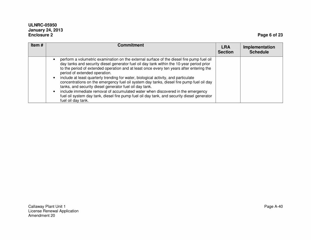
• perform a volumetric examination on the external surface of the diesel fire pump fuel oil day tanks and security diesel generator fuel oil day tank within the 10-year period prior to the period of extended operation and at least once every ten years after entering the period of extended operation.
• include at least quarterly trending for water, biological activity, and particulate concentrations on the emergency fuel oil system day tanks, diesel fire pump fuel oil day tanks, and security diesel generator fuel oil day tank.
• include immediate removal of accumulated water when discovered in the emergency fuel oil system day tank, diesel fire pump fuel oil day tank, and security diesel generator fuel oil day tank.
ULNRC-05950 January 24, 2013 Enclosure 2 Page 7 of 23
Callaway Plant Unit 1 Page A-43 License Renewal Application Amendment 20
Table A4-1 License Renewal Commitments
Item #
Commitment LRA Section
Implementation Schedule
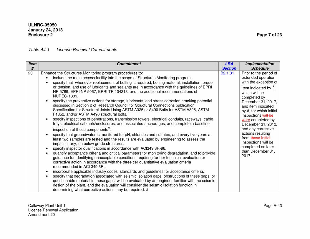
23 Enhance the Structures Monitoring program procedures to: • include the main access facility into the scope of Structures Monitoring program.
• specify that whenever replacement of bolting is required, bolting material, installation torque or tension, and use of lubricants and sealants are in accordance with the guidelines of EPRI NP 5769, EPRI NP 5067, EPRI TR 104213, and the additional recommendations of NUREG-1339.
• specify the preventive actions for storage, lubricants, and stress corrosion cracking potential discussed in Section 2 of Research Council for Structural Connections publication Specification for Structural Joints Using ASTM A325 or A490 Bolts for ASTM A325, ASTM F1852, and/or ASTM A490 structural bolts.
• specify inspections of penetrations, transmission towers, electrical conduits, raceways, cable trays, electrical cabinets/enclosures, and associated anchorages, and complete a baseline
inspection of these components*.
• specify that groundwater is monitored for pH, chlorides and sulfates, and every five years at least two samples are tested and the results are evaluated by engineering to assess the impact, if any, on below grade structures.
• specify inspector qualifications in accordance with ACI349.3R-96.
• quantify acceptance criteria and critical parameters for monitoring degradation, and to provide guidance for identifying unacceptable conditions requiring further technical evaluation or corrective action in accordance with the three tier quantitative evaluation criteria recommended in ACI 349.3R.
• incorporate applicable industry codes, standards and guidelines for acceptance criteria. • specify that degradation associated with seismic isolation gaps, obstructions of these gaps, or
questionable material in these gaps, will be evaluated by an engineer familiar with the seismic design of the plant, and the evaluation will consider the seismic isolation function in determining what corrective actions may be required. #
B2.1.31 Prior to the period of extended operation with the exception of
item indicated by *,
which will be completed by December 31, 2017, and item indicated by #, for which initial inspections will be were completed by December 31, 2012, and any corrective actions resulting from these initial inspections will be completed no later than December 31, 2017.

ULNRC-05950 January 24, 2013 Enclosure 2 Page 8 of 23
Callaway Plant Unit 1 Page B-53 License Renewal Application Amendment 20
Appendix B AGING MANAGEMENT PROGRAMS
B2.1.14 Fire Water System
Program Description
The Fire Water System program manages loss of material for water-based fire protection systems consisting of aboveground, buried and underground piping, fittings, valves, fire pump casings, sprinklers, nozzles, hydrants, hose stations, standpipes and water storage tanks. Periodic fire main and hydrant inspections and flushing, sprinkler inspections, functional test, and flow tests in accordance with National Fire Protection Association (NFPA) codes and standards ensure that the water-based fire protection systems are capable of performing their intended function. The fire protection system is maintained at the required normal operating pressure and monitored such that a loss of system pressure is immediately detected and corrective actions initiated.
The Fire Water System program performs a flow test of the system at least once every three years in accordance with plant procedures meeting the requirements of NFPA 25, including a yard fire loop flush and a flush of associated hydrants. A visual inspection and flow test of yard fire hydrants is performed annually in accordance with NFPA 25.
The Fire Water System program conducts flow tests through each open head spray/sprinkler nozzle in accordance with NFPA 25, to verify water flow is unobstructed. Prior to 50 years in service, the Fire Water System program requires sprinkler heads to be replaced or have representative samples submitted for field-service testing by a recognized testing laboratory in accordance with NFPA 25. The program field-service tests additional representative samples every 10 years thereafter during the period of extended operation to ensure signs of aging are detected in a timely manner.
Pipe wall thickness examinations are performed on fire water piping using non-intrusive techniques. Wall thickness examinations will be performed on fire water piping every three years. Each three year sample will include at least three locations for a total of 100 feet of above-ground fire water piping and be selected based on system susceptibility to corrosion or fouling and evidence of performance degradation during system flow testing or periodic flushes. The basis for the frequency is that three years is the frequency required by the FSAR for the yard fire loop flush and for the flow tests of the fire water loops. In addition, internal inspections are performed on accessible exposed portions of fire water piping during plant maintenance activities. The inspections evaluate wall thickness measurements to ensure against catastrophic failure and the inner diameter of the piping as it applies to the design flow of the fire protection system. If a representative number of inspections have not been completed prior to the period of extended operation, Callaway will determine what additional inspections or examinations are required. The representative sample will be selected, based on system susceptibility to corrosion or fouling and evidence of performance degradation during system flow testing or periodic flushes. If material and environment conditions for above grade and below grade piping are similar, the results of the inspections
ULNRC-05950 January 24, 2013 Enclosure 2 Page 9 of 23
Callaway Plant Unit 1 Page B-54 License Renewal Application Amendment 20
Appendix B AGING MANAGEMENT PROGRAMS
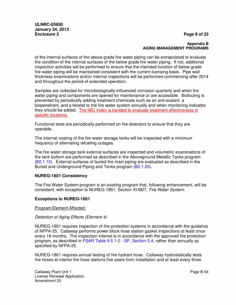
of the internal surfaces of the above grade fire water piping can be extrapolated to evaluate the condition of the internal surfaces of the below grade fire water piping. If not, additional inspection activities will be performed to ensure that the intended function of below grade fire water piping will be maintained consistent with the current licensing basis. Pipe wall thickness examinations and/or internal inspections will be performed commencing after 2014 and throughout the period of extended operation.
Samples are collected for microbiologically-influenced corrosion quarterly and when fire water piping and components are opened for maintenance or are accessible. Biofouling is prevented by periodically adding treatment chemicals such as an anti-scalant, a biopenetrant, and a biostat to the fire water system annually and when monitoring indicates they should be added. The MIC Index is trended to evaluate treatment effectiveness in specific locations.
Functional tests are periodically performed on fire detectors to ensure that they are operable.
The internal coating of the fire water storage tanks will be inspected with a minimum frequency of alternating refueling outages.
The fire water storage tank external surfaces are inspected and volumetric examinations of the tank bottom are performed as described in the Aboveground Metallic Tanks program (B2.1.15). External surfaces of buried fire main piping are evaluated as described in the Buried and Underground Piping and Tanks program (B2.1.25).
NUREG-1801 Consistency
The Fire Water System program is an existing program that, following enhancement, will be consistent, with exception to NUREG-1801, Section XI.M27, Fire Water System.
Exceptions to NUREG-1801
Program Element Affected:
Detection of Aging Effects (Element 4)
NUREG-1801 requires inspection of fire protection systems in accordance with the guidance of NFPA-25. Callaway performs power block hose station gasket inspections at least once every 18 months. The inspection interval is in accordance with the approved fire protection program, as described in FSAR Table 9.5.1-2 - SP, Section 5.4, rather than annually as specified by NFPA-25.
NUREG-1801 requires annual testing of fire hydrant hose. Callaway hydrostatically tests fire hoses at interior fire hose stations five years from installation and at least every three
ULNRC-05950 January 24, 2013 Enclosure 2 Page 10 of 23
Callaway Plant Unit 1 Page B-55 License Renewal Application Amendment 20
Appendix B AGING MANAGEMENT PROGRAMS
years thereafter. The testing interval is in accordance with the approved fire protection program, as described in FSAR Table 9.5.1-2 - SP, Section 5.6.
Enhancements
Prior to the period of extended operation, the following enhancements will be implemented in the following program elements:
Preventive Actions (Element 2)
The Fire Water Storage Tanks internal surfaces will be recoated prior to the period of extended operation.
Parameters Monitored or Inspected (Element 3), Detection of Aging Effects (Element 4), and Acceptance Criteria (Element 6)
The Fire Water System program will be enhanced to include non-intrusive pipe wall thickness examinations. Wall thickness measurements will be performed on fire water piping every three years. Each three year sample will include at least three locations for a total of 100 feet of above-ground fire water piping, and will be selected based on system susceptibility to corrosion or fouling and evidence of performance degradation during system flow testing or periodic flushes. In addition, internal inspections will be performed on accessible exposed portions of fire water piping during plant maintenance activities. Pipe wall thickness examinations and internal inspections will be performed commencing after 2014 and throughout the period of extended operation.
Detection of Aging Effects (Element 4)
The Fire Water System program will be enhanced to include annual hydrostatic testing of fire brigade hose.
The Fire Water System program will be enhanced such that prior to 50 years in service, sprinkler heads will be replaced or representative samples will be submitted for field-service testing by a recognized testing laboratory in accordance with NFPA 25. The program will field-service test additional representative samples every 10 years thereafter to ensure signs of aging are detected in a timely manner.
Detection of Aging Effects (Element 4) and Acceptance Criteria (Element 6)
The Fire Water System program will be enhanced to include annual hydrant flow testing in accordance with NFPA 25.
Monitoring and Trending (Element 5)
The Fire Water System program will be enhanced to review and evaluate trends in flow parameters recorded during the NFPA 25 fire water flow tests.

ULNRC-05950 January 24, 2013 Enclosure 2 Page 11 of 23
Callaway Plant Unit 1 Page B-56 License Renewal Application Amendment 20
Appendix B AGING MANAGEMENT PROGRAMS
Operating Experience
The following discussion of operating experience provides objective evidence that the Fire Water System program will be effective in ensuring that intended functions are maintained consistent with the current licensing basis for the period of extended operation.
1. In 2005, during a surveillance test, 10 sprinkler heads had signs of corrosion or mechanical damage. Two of the sprinkler heads were replaced, and the other eight were cleaned. There have been no additional issues with the sprinkler heads since then.
2. In 2005 an alarm was triggered for fire protection loop jockey pump excessive run time and an investigation was initiated to identify the leak. The location of the leak was determined and promptly isolated from the main fire water loop. The isolation of the leak did not affect any required suppression systems. The leak was promptly repaired and the fire water piping was returned to service.
3. In 2006, a low C-factor lead to the fire water system being chemically cleaned, resulting in removal of approximately 8900 pounds of corrosion products. The cleaning was successful in keeping the system C-factor above 91.5 as required by plant procedure. During the chemical cleaning, five leaks developed, all of which were repaired. Since that time, two additional leaks have occurred. One was due to a cracked valve, and the cause of the other is still under investigation.
4. In 2008, during microbiological sampling of the fire water system, elevated levels of microbiologically influenced corrosion (MIC) were detected in stagnant portions of fire water pipe supplying fire water to hose stations. As a result, a new preventive maintenance task has been created to flush hose stations with a biocide.
5. In 2011, C-factor testing was performed on the main fire loop piping to check for restrictions due to corrosion and or biofouling. The testing results did not meet the acceptance criteria, indicating excessive pressure drop leading to reduced fire water flow. The testing results were called into question so with more accurate digital crystal gauges, the system was reevaluated and the results improved by 6% to 89.5, still less than the required acceptance criteria of 91.5. A functionality determination concluded that provided compensatory measures were taken, the reduced cleanliness could be fully offset so the required fire water flow rate could be achieved and maintained. As a corrective action, the acceptance criteria in Calculation KC-005 Addendum 2 have been modified, and the test procedure updated accordingly. These revisions provide significant margin and consider the cleanliness trends, ensuring the fire water system is capable of performing its intended function.
The above examples provide objective evidence that the existing Fire Water System program includes activities that are capable of detecting aging effects, evaluating system leakage, and initiating corrective actions. Occurrences that would be identified under the
ULNRC-05950 January 24, 2013 Enclosure 2 Page 12 of 23
Callaway Plant Unit 1 Page B-57 License Renewal Application Amendment 20
Appendix B AGING MANAGEMENT PROGRAMS
Fire Water System program will be evaluated to ensure there is no significant impact to safe operation of the plant and corrective actions will be taken to prevent recurrence. Guidance for re-evaluation, repair, or replacement is provided for locations where aging is found. There is confidence that the continued implementation of the Fire Water System program will effectively identify aging prior to loss of intended function.
Conclusion
The continued implementation of the Fire Water System program, following enhancement, provides reasonable assurance that aging effects will be managed such that the systems and components within the scope of this program will continue to perform their intended functions consistent with the current licensing basis for the period of extended operation.

ULNRC-05950 January 24, 2013 Enclosure 2 Page 13 of 23
Callaway Plant Unit 1 Page B-87 License Renewal Application Amendment 20
Appendix B AGING MANAGEMENT PROGRAMS
B2.1.25 Buried and Underground Piping and Tanks
Program Description
The Buried and Underground Piping and Tanks program manages loss of material, cracking, blistering, and changes in color of external surfaces of buried and underground piping and tanks. The program augments other programs that manage the aging of internal surfaces of buried and underground piping and tanks. The materials managed by this program include steel, stainless steel and high-density polyethylene. The program manages aging through preventive, mitigative, and inspection activities.
Preventive and mitigative actions include the selection of component materials, external coatings for corrosion control, backfill quality control, and the application of cathodic protection. The cathodic protection system is operated consistent with the guidance of NACE SP 0169-2007 for piping and NACE RP 0285-2002 for tanks. Trending of the cathodic protection system is performed to identify changes in the effectiveness of the system and to ensure that the rectifiers are available to protect buried components. An annual cathodic protection survey is performed consistent with NACE SP 0169-2007. Corrosion coupons are used to ensure that the cathodic protection system is providing sufficient protection for buried steel components within the scope of license renewal.
Soil samples will be conducted during the 10-year period prior to the period of extended operation and in each subsequent 10-year period during the period of extended operation. Soil samples will be performed in the vicinity of buried steel piping in which the cathodic protection system does not meet the following availability or effectiveness requirements:
• Cathodic protection has been operational (available) at least 85 percent of the time since either 10 years prior to the period of extended operation or since installation/refurbishment, whichever is shorter; or
• Cathodic protection has provided effective protection for buried piping as evidenced by meeting the acceptance criteria of -850 mV relative to a copper/copper sulfate electrode, instant off, at least 80 percent of the time since either 10 years prior to the period of extended operation or since installation/refurbishment, whichever is shorter.
Inspection activities may include nondestructive evaluation of pipe and tank wall thicknesses, and visual inspections of pipe and tank exterior surfaces, as permitted by opportunistic or directed excavations. The fire protection system jockey pump is monitored to identify changes in jockey pump activity.
Direct visual inspections will be performed on buried steel piping, stainless steel piping, and carbon steel tanks. Inspection locations will be selected based on susceptibility to degradation and consequences of failure. A minimum of 10 feet of pipe of each material

ULNRC-05950 January 24, 2013 Enclosure 2 Page 14 of 23
Callaway Plant Unit 1 Page B-88 License Renewal Application Amendment 20
Appendix B AGING MANAGEMENT PROGRAMS
type must be inspected. The inspection will consist of a 100 percent visual inspection of the exposed pipe. If adverse indications are detected, inspection sample sizes within the affected piping categories are doubled. If adverse indications are found in the expanded sample, further increases in inspection sample size would be based on an analysis of extent of cause and extent of condition. Visual inspections will be supplemented with surface or volumetric nondestructive testing (NDT) if significant indications are observed, to determine local area wall thickness. All buried high density polyethylene piping is encased in controlled low strength material; therefore, no direct visual inspections are required.
Direct visual inspections will be performed on underground steel, stainless steel and high density polyethylene piping, tank access covers, and valves to detect external corrosion. Inspection locations will be selected based on susceptibility to degradation and consequences of failure.
Inspections will begin during the 10-year period prior to entering the period of extended operation. Upon entering the period of extended operation, inspections will occur every 10 years.
The internal surfaces of buried and underground piping and tanks are managed through other programs. Internal surfaces may be managed by the Open-Cycle Cooling Water System (B2.1.10), Closed Treated Water Systems (B2.1.11), Inspection of Internal Surfaces in Miscellaneous Piping and Ducting Components (B2.1.23), Fuel Oil Chemistry (B2.1.16), Fire Water System (B2.1.14) or Water Chemistry (B2.1.2) programs. The Selective Leaching program (B2.1.19) works in conjunction with this program to manage buried or underground components subject to selective leaching.
NUREG-1801 Consistency
The Buried and Underground Piping and Tanks program is a new program that, when implemented, will be consistent with NUREG-1801, Section XI.M41, Buried and Underground Piping and Tanks.
Exceptions to NUREG-1801
None
Enhancements
None
ULNRC-05950 January 24, 2013 Enclosure 2 Page 15 of 23
Callaway Plant Unit 1 Page B-89 License Renewal Application Amendment 20
Appendix B AGING MANAGEMENT PROGRAMS
Operating Experience
The following discussion of operating experience provides objective evidence that the Buried and Underground Piping and Tanks program will be effective in ensuring that intended functions are maintained consistent with the current licensing basis for the period of extended operation:
1. In the winter of 2005, an alarm was triggered for fire protection loop jockey pump excessive run time and an investigation was initiated. The location of the leak was determined and promptly isolated from the main fire water loop. The isolation of the leak did not affect any required suppression systems. The leak was promptly repaired and the fire water piping was returned to service.
2. Prior to Refuel 15 (Spring 2007), Close Interval Surveys (CIS) were performed on various tanks and associated piping systems to identify cathodic protection effectiveness. The CIS testing measures cathodic protection levels along the pipeline at approximately 2.5 foot intervals. These surveys were performed on the following structures and components within the scope of license renewal: emergency fuel oil storage tanks, fire water storage tank bottoms, ESW system piping, and condensate storage tank piping. The results indicated that emergency fuel oil storage tanks, condensate storage tank piping, and one quadrant of the fire water storage tank, were not meeting the 850mV polarization potential criterion of the National Association of Corrosion Engineers (NACE). Corrective actions were taken to correct these deficiencies by adjusting the cathodic protection where possible. In some instances the cathodic protection system could not be adjusted to correct a condition. Cathodic protection system refurbishment and modifications are planned in areas where the system does not meet the NACE criteria.
3. From 2008 to 2009, the underground portions of the ESW supply from the ESW pump house and return to the ultimate heat sink cooling tower were replaced with HDPE piping. In addition, sections of above ground or underground carbon steel piping that interfaces with the buried piping was replaced with stainless steel piping. These modifications were performed as a result of the material condition of the ESW system. These modifications were performed as a result of corrective action documents that have been written concerning pinhole leaks, pitting, and other localized degradation of the ESW piping system.
4. In the summer of 2011, the annual cathodic protection survey was performed. Several locations in the fire water system had a negative potential below the NACE criteria of 850 mV. Modification and refurbishment of the cathodic protection system will address areas of low negative potential identified during the annual survey and the CIS described above.
ULNRC-05950 January 24, 2013 Enclosure 2 Page 16 of 23
Callaway Plant Unit 1 Page B-90 License Renewal Application Amendment 20
Appendix B AGING MANAGEMENT PROGRAMS
5. Due to industry operating experience with buried condensate system piping, Callaway reviewed cathodic protection records related to the buried carbon steel piping for the condensate storage tank to determine if the external corrosion control provided for this piping was adequate. The review of the cathodic protection for this line found that the negative potential was below the NACE criteria. The cathodic protection system will be refurbished/modified in areas where it does not meet the NACE criteria. The buried portion of the condensate storage tank suction line will be inspected prior to the period of extended operation.
Inspection and preventive measures that will be implemented by the Buried and Underground Piping and Tanks program will be effective in managing aging of underground and buried components. Occurrences that would be identified under the Buried and Underground Piping and Tanks program will be evaluated to ensure there is no significant impact to safe operation of the plant and corrective actions will be taken to prevent recurrence. Guidance for re-evaluation, repair, or replacement is provided for locations where aging is found. There is confidence that the implementation of the Buried and Underground Piping and Tanks program will effectively identify aging prior to loss of intended function.
Industry and plant-specific operating experience will be evaluated in the development and implementation of this program.
Conclusion
The implementation of the Buried and Underground Piping and Tanks program will provide reasonable assurance that aging effects will be managed such that the systems and components within the scope of this program will continue to perform their intended functions consistent with the current licensing basis for the period of extended operation.
ULNRC-05950 January 24, 2013 Enclosure 2 Page 17 of 23
Callaway Plant Unit 1 Page B-94 License Renewal Application Amendment 20
Appendix B AGING MANAGEMENT PROGRAMS
B2.1.27 ASME Section XI, Subsection IWL
Program Description
The ASME Section XI, Subsection IWL program manages the following aging effects of the concrete containment building and post-tensioned system:
• Cracking
• Cracking, loss of bond, and loss of material (spalling, scaling)
• Increase in porosity and permeability, cracking, loss of material (spalling, scaling)
• Increase in porosity and permeability, loss of strength
• Loss of material
• Loss of material (spalling, scaling) and cracking
For the current inspection interval, Callaway performs IWL Containment Inservice Inspections (CISIs) in accordance with the 2001 Edition of ASME Section XI, Subsection IWL (including 2002 and 2003 addenda), supplemented with the applicable requirements of 10 CFR 50.55a(b)(2). This program is consistent with provisions in 10 CFR 50.55a that specify use of the ASME Code edition in effect 12 months prior to the start of the inspection interval. Callaway will use the ASME Code edition consistent with the provisions of 10 CFR 50.55a during the period of extended operation.
The ASME Section XI, Subsection IWL inspections are performed in order to identify and manage containment concrete aging effects that could result in loss of intended function. Included in this inspection program are the concrete containment structure (includes all accessible areas of the concrete dome, cylinder walls, and buttresses) and the post-tensioning system (includes tendons, end anchorages, and concrete surfaces around the end anchorages). A summary of the containment concrete components at Callaway, the examinations required, and a detailed schedule of examinations for items subject to IWL inspections are provided in plant procedures. The primary inspection method is a visual examination, supplemented by testing. Tendon wires are tested for yield strength, ultimate tensile strength, and elongation. Tendon corrosion protection medium is analyzed for alkalinity, water content, and soluble ion concentrations. Any free water contained in the anchorage end cap and free water which drains from tendons during the examination is documented. Samples of the free water are also analyzed for pH. Prestressing forces are measured in selected sample tendons. Evaluation of prestressing forces is addressed in Concrete Containment Tendon Prestress program (B3.3). Acceptance criteria, corrective actions, and expansion of the inspection scope when degradation exceeding the acceptance criteria is found, are in accordance with ASME Section XI, Subsection IWL.
.
ULNRC-05950 January 24, 2013 Enclosure 2 Page 18 of 23
Callaway Plant Unit 1 Page B-95 License Renewal Application Amendment 20
Appendix B AGING MANAGEMENT PROGRAMS
Post-tensioning system repair/replacement activities and the augmented examination requirements following post-tensioning system repair/replacement activities are in accordance with ASME Section XI, Subsection IWL.
In conformance with 10 CFR 50.55a(g)(4)(ii), the Callaway CISI program will be updated during each successive 120-month inspection interval to comply with the requirements of the latest edition and addenda of the Code specified 12 months before the start of the inspection interval.
NUREG-1801 Consistency
The ASME Section XI, Subsection IWL program is an existing program that, following enhancement, will beis consistent with NUREG-1801, Section XI.S2, ASME Section XI, Subsection IWL.
Exceptions to NUREG-1801
None
Enhancements Prior to the period of extended operation, the following enhancement will be implemented in the following program element: Acceptance Criteria (Element 6)
Plant procedures will be enhanced to specify that acceptability of concrete surfaces is based on the evaluation criteria provided in ACI-349.3R.
Operating Experience
The following discussion of operating experience provides objective evidence that the ASME Section XI, Subsection IWL program will be effective in ensuring that intended functions are maintained consistent with the current licensing basis for the period of extended operation:
1. The 15th year tendon surveillance began in May 1999 and was completed in June 1999. Based on the data gathered during the 1999 physical surveillance and visual inspection, the conclusion was reached that no abnormal degradation of the post tensioning system had occurred at the Callaway containment building.
2. The 20th year tendon surveillance began in July 2004 and was completed in September 2004. All tendons were resealed and regreased. One tendon accepted less grease than was removed, and one tendon accepted more than 10 percent of the tendon duct volume. Nonconformance reports were written to record these findings and these conditions were found to be acceptable by engineering evaluation, as allowed by ASME.
ULNRC-05950 January 24, 2013 Enclosure 2 Page 19 of 23
Callaway Plant Unit 1 Page B-96 License Renewal Application Amendment 20
Appendix B AGING MANAGEMENT PROGRAMS
Section XI, Subsection IWL-3310. Based on these evaluations and the other data gathered during the 2004 physical surveillance and visual inspection, the conclusion was reached that no abnormal degradation of the post tensioning system had occurred at the Callaway containment building.
3. The 25th year tendon surveillance began in March 2010 and was completed in April 2010. Sample wires were removed from one tendon in each group for physical testing. The test results on one of the wire samples indicated elongation values under the minimum prescribed in Callaway specifications. A nonconformance report was written to record this finding, and this condition was found to be acceptable by engineering evaluation, as allowed by ASME Section XI, Subsection IWL-3310. Based on this evaluation and the other data gathered during the 2010 physical surveillance and visual inspection, the conclusion was reached that no abnormal degradation of the post tensioning system had occurred at the Callaway containment building.
The above examples provide objective evidence that the ASME Section XI, Subsection IWL program is capable of both monitoring and detecting the aging effects associated with the program. Occurrences that would be identified under the ASME Section XI, Subsection IWL program will be evaluated to ensure there is no significant impact to safe operation of the plant and corrective actions will be taken to prevent recurrence. Guidance for re-evaluation, repair, or replacement is provided for locations where aging is found. There is confidence that the continued implementation of the ASME Section XI, Subsection IWL program will effectively identify aging prior to loss of intended function.
Conclusion
The continued implementation of the ASME Section XI, Subsection IWL program, following enhancement, provides reasonable assurance that aging effects will be managed such that the systems and components within the scope of this program will continue to perform their intended functions consistent with the current licensing basis for the period of extended operation.

ULNRC-05950 January 24, 2013 Enclosure 2 Page 20 of 23
Callaway Plant Unit 1 Page B-104 License Renewal Application Amendment 20
Appendix B AGING MANAGEMENT PROGRAMS
B2.1.31 Structures Monitoring
Program Description
The Structures Monitoring program (SMP) monitors the condition of structures and structural supports that are within the scope of license renewal to manage the following aging effects:
• Concrete cracking and spalling • Cracking
• Cracking and distortion
• Cracking, blistering, change in color
• Cracking, loss of material
• Cracking, loss of bond, and loss of material (spalling, scaling) • Increase in porosity and permeability, cracking, loss of material (spalling, scaling)
• Increase in porosity and permeability, loss of strength
• Loss of material
• Loss of material (spalling, scaling) and cracking
• Loss of mechanical function • Loss of preload
• Loss of sealing
• Reduction in concrete anchor capacity
Plant procedures, following enhancements, will specify that whenever replacement of bolting is required, bolting material, installation torque or tension, and use of lubricants and sealants are in accordance with the guidelines of EPRI NP-5769, Degradation and Failure of Bolting in Nuclear Power Plants, EPRI NP-5067, Good Bolting Practices, A Reference Manual for Nuclear Power Plant Maintenance Personnel, EPRI TR-104213, Bolted Joint Maintenance & Application Guide, and the additional recommendations of NUREG-1339, Resolution of Generic Safety Issue 29: Bolting Degradation or Failure in Nuclear Power Plants.
The SMP implements the requirements of 10 CFR 50.65, Requirements for Monitoring the Effectiveness of Maintenance at Nuclear Power Plants, consistent with guidance of NUMARC 93-01, Industry Guidelines for Monitoring the Effectiveness of Maintenance at Nuclear Power Plants, Revision 2 and Regulatory Guide 1.160, Monitoring the Effectiveness of Maintenance at Nuclear Power Plants, Revision 2.
The SMP provides inspection guidelines and walk-down checklists for structural steel, roof systems, reinforced concrete, masonry walls and metal siding. Electrical duct banks and manholes, valve pits, access vaults, and structural supports are inspected as part of the SMP. Callaway is committed to NRC Regulatory Guide 1.127, Inspection of Water-Control Structures Associated with Nuclear Power Plants and the scope of the SMP includes water-control structures. The scope of SMP also includes masonry walls. Callaway has a settlement monitoring program that monitors settlement for each major structure utilizing geotechnical monitoring techniques. The inspections of all structural components, include

ULNRC-05950 January 24, 2013 Enclosure 2 Page 21 of 23
Callaway Plant Unit 1 Page B-105 License Renewal Application Amendment 20
Appendix B AGING MANAGEMENT PROGRAMS
masonry walls and water-control structures, are performed at intervals of no more than 5 years.
Groundwater is monitored for pH, chlorides and sulfates every five years, and the results are evaluated by engineering to assess the impact, if any, on below grade structures.
Callaway does not take credit for any coatings to manage the aging of structural components and coating degradation is used only as an indicator of the condition of underlying material.
NUREG-1801 Consistency
The Structures Monitoring program is an existing program that, following enhancement, will be consistent with NUREG-1801, Section XI.S6, Structures Monitoring.
Exceptions to NUREG-1801
None
Enhancements
Prior to the period of extended operation, the following enhancements will be implemented in the following program elements:
Scope of the Program (Element 1)
Procedures will be enhanced to include the main access facility into the scope of Structures Monitoring program.
Preventive Actions (Element 2)
Plant procedures will be enhanced to specify that whenever replacement of bolting is required, bolting material, installation torque or tension, and use of lubricants and sealants are in accordance with the guidelines of EPRI NP-5769, EPRI NP-5067, EPRI TR-104213, and the additional recommendations of NUREG-1339.
Plant procedures will be enhanced to specify the preventive actions for storage, lubricants, and stress corrosion cracking potential discussed in Section 2 of Research Council for Structural Connections publication Specification for Structural Joints Using ASTM A325 or A490 Bolts for ASTM A325, ASTM F1852, and/or ASTM A490 structural bolts.
Scope of the Program (Element 1) and Parameters Monitored or Inspected (Element 3)
Procedures will be enhanced to specify inspections of penetrations, transmission towers, electrical conduits, raceways, cable trays, electrical cabinets/enclosures, and associated anchorages, and to complete a baseline inspection of these components prior to December 31, 2017.
ULNRC-05950 January 24, 2013 Enclosure 2 Page 22 of 23
Callaway Plant Unit 1 Page B-106 License Renewal Application Amendment 20
Appendix B AGING MANAGEMENT PROGRAMS
Procedures will be enhanced to specify that groundwater is monitored for pH, chlorides and sulfates, and every five years at least two samples are tested and the results are evaluated by engineering to assess the impact, if any, on below grade structures.
Detection of Aging Effects (Element 4)
Procedures will be enhanced to specify inspector qualifications in accordance with ACI349.3R-96.
Acceptance Criteria (Element 6)
Procedures will be enhanced to quantify acceptance criteria and critical parameters for monitoring degradation, and to provide guidance for identifying unacceptable conditions requiring further technical evaluation or corrective action in accordance with the three tier quantitative evaluation criteria recommended in ACI 349.3R.
Procedures will be enhanced to incorporate applicable industry codes, standards and guidelines for acceptance criteria.
Procedures will be enhanced to specify that degradation associated with seismic isolation gaps, obstructions of these gaps, or questionable material in these gaps, will be evaluated by an engineer familiar with the seismic design of the plant, and the evaluation will consider the seismic isolation function in determining what corrective actions may be required. Initial inspections in accordance with these criteria have been completed, and corrective actions resulting from these initial inspections will be completed no later than December 31, 2017.Initial inspections will be completed by December 31, 2012, and any corrective actions resulting from these inspections will be completed no later than December 31, 2017.
Operating Experience
The following discussion of operating experience provides objective evidence that the Structures Monitoring program will be effective in ensuring that intended functions are maintained consistent with the current licensing basis for the period of extended operation:
1. A review of the most recent structure inspection reports show minor instances of cracking in concrete, corrosion in structural steel, and elastomeric degradation in various building structures which have been evaluated per acceptance criteria and with corrective action taken as needed. The northeast corner of the ‘A' emergency diesel generator fuel vault exterior exhibited some cracking in 2010, which is not severe enough to warrant corrective action at this time but is tracked for trending purposes. The most recent reactor building inspection report (2010) cites instances of corrosion of structural steel, supports, and cable trays due to condensation.
2. Fuel building structural inspection report (2002) identified an instance of cracking on the interior face of the exterior wall, with leachate observed coming through the crack. Engineering evaluation determined this leaking was not severe enough to warrant corrective action. Inspections performed in 2010 did not identify any further cracking or leaking of leachate in this area. Minor cracking on the exterior of fuel building plant
ULNRC-05950 January 24, 2013 Enclosure 2 Page 23 of 23
Callaway Plant Unit 1 Page B-107 License Renewal Application Amendment 20
Appendix B AGING MANAGEMENT PROGRAMS
south and west wall was identified and no water leakage, either active or inactive, was observed. Callaway performs continuous monitoring of the spent fuel pool liner leak chase channels. A standpipe with automatic drain controls is used to measure the fuel pool leak rate and periodic updates of the leak rate are provided by the plant computer. The observed leakage has been small and remained steady. The leakage rate is small at approximately 0.119 gal/day, and does not challenge makeup capability. The exterior spent fuel pool walls show no evidence of external leakage, thus indicating that the leakage is contained within the leak chase channels and that there is no effect upon the structural integrity of the spent fuel pool.
3. Groundwater has been sampled monthly since November, 2009. With exception of two monitoring wells, pH, chlorides and sulfate concentrations have been within the prescribed limits for non-aggressive ground water/soil. These two wells are located north of the turbine building and adjacent to plant roads. The wells’ high chloride levels can be attributed to the use of winter road salts. These two well locations have shown seasonal increases in chloride levels of up to 680 mg/L while the pH and sulfate concentrations have remained non-aggressive. Callaway will continue to monitor the results from the groundwater samples and will perform an engineering evaluation to determine if any adverse aging effects have occurred in any inaccessible concrete structural elements.
The above examples provide objective evidence that the Structures Monitoring program is capable of both monitoring and detecting the aging effects associated with the program. Occurrences that would be identified under the Structures Monitoring program will be evaluated to ensure there is no significant impact to safe operation of the plant and corrective actions will be taken to prevent recurrence. Guidance for re-evaluation, repair, or replacement is provided for locations where aging is found. There is confidence that the continued implementation of the Structures Monitoring program will effectively identify aging prior to loss of intended function.
Conclusion
The continued implementation of the Structures Monitoring program, following enhancement, provides reasonable assurance that aging effects will be managed such that the systems and components within the scope of this program will continue to perform their intended functions consistent with the current licensing basis for the period of extended operation.