Embed Size (px)
Citation preview

Engineering mechanics provides excel-lent theoretical descriptions for the ra-tional design of materials and accuratelifetime prediction of mechanical struc-
tures. This approach deals with continuous quan-tities such as strain field that are functions of bothspace and time. Constitutive relations such asHooke’s law for deformation and Coulomb’s lawfor friction describe the relationships betweenthese macroscopic fields. These constitutiveequations contain material-specific parameterssuch as elastic moduli and friction coefficients,
which are often size dependent. For example, themechanical strength of materials is inversely pro-portional to the square root of the grain size, ac-cording to the Hall-Petch relationship.
Such scaling laws are usually validated experi-mentally at length scales above a micron, but in-terest is growing in extending constitutive rela-tions and scaling laws down to a few nanometers.This is because many experts believe that by re-ducing the structural scale (such as grain sizes)to the nanometer range, we can extend materialproperties such as strength and toughness be-yond the current engineering-materials limit.1
In addition, widespread use of nanoelectro-mechanical systems (NEMS) is making theirdurability a critical issue, to which scaling downengineering-mechanics concepts is essential.Because of the large surface-to-volume ratios inthese nanoscale systems, new engineering-mechanics concepts reflecting the enhanced roleof interfacial processes might even be necessary.
Atomistic simulations will likely play an im-portant role in scaling down engineering-mechanics concepts to nanometer scales. Recentadvances in computational methodologies andmassively parallel computers have let re-searchers carry out 10- to 100-million-atomatomistic simulations (the typical linear dimen-
56 COMPUTING IN SCIENCE & ENGINEERING
MULTISCALE SIMULATION OFNANOSYSTEMS
The authors describe simulation approaches that seamlessly combine continuummechanics with atomistic simulations and quantum mechanics. They also discusscomputational and visualization issues associated with these simulations on massivelyparallel computers.
N A N O T E C H N O L O G Y
AIICHIRO NAKANO, MARTINA E. BACHLECHNER, RAJIV K. KALIA, ELEFTERIOS LIDORIKIS, PRIYA VASHISHTA, AND GEORGE Z. VOYIADJIS
Louisiana State UniversityTIMOTHY J. CAMPBELL
Logicon Inc. and Naval Oceanographic Office Major Shared Resource CenterSHUJI OGATA
Yamaguchi UniversityFUYUKI SHIMOJO
Hiroshima University
1521-9615/01/$10.00 © 2001 IEEE
Authorized licensed use limited to: UNIVERSITY OF OSLO. Downloaded on January 14, 2009 at 04:59 from IEEE Xplore. Restrictions apply.
JULY/AUGUST 2001 57
sion ranges from 50 to 100 nanometers) of realmaterials.2 To successfully design and fabricatenovel nanoscale systems, we must bridge the gapin our understanding of mechanical propertiesand processes at length scales ranging from 100nanometers (where atomistic simulations arecurrently possible) to a micron (where contin-uum mechanics is experimentally validated). Toachieve this goal, scientists are combining con-tinuum mechanics and atomistic simulationsthrough integrated multidisciplinary efforts sothat a single simulation couples diverse lengthscales. However, the complexity of these hybridschemes poses an unprecedented challenge, anddevelopments in scalable parallel algorithms aswell as interactive and immersive visualizationare crucial for their success. This article de-scribes such multiscale simulation approachesand associated computational issues using ourrecent work as an example.
The multiscale-simulation approach
Processes such as crack propagation and frac-ture in real materials involve structures on manydifferent length scales. They occur on a macro-scopic scale but require atomic-level resolutionin highly nonlinear regions. To study such multi-scale materials processes, we need a multiscale-simulation approach that can describe physicaland mechanical processes over several decadesof length scales. Farid Abraham and his col-leagues have developed a hybrid simulation ap-proach that combines quantum-mechanical cal-culations with large-scale molecular-dynamicssimulations embedded in a continuum, whichthey handle with the finite-element approachbased on linear elasticity.3,4
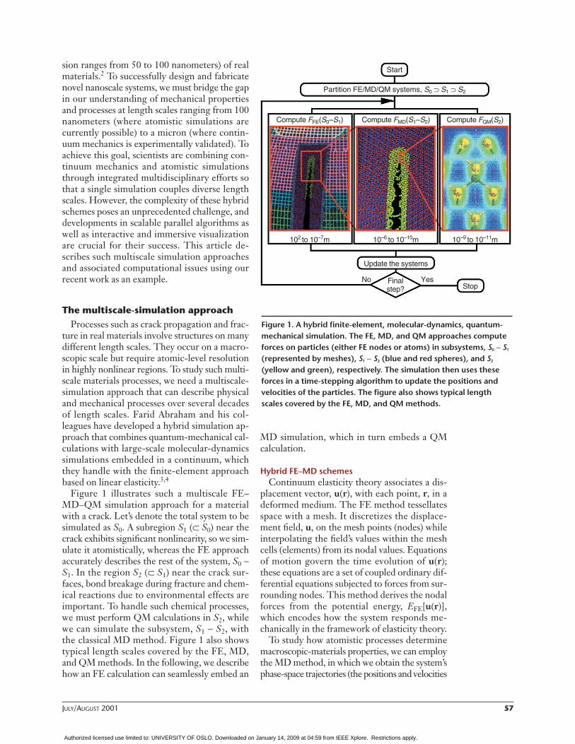
Figure 1 illustrates such a multiscale FE–MD–QM simulation approach for a materialwith a crack. Let’s denote the total system to besimulated as S0. A subregion S1 (⊂ S0) near thecrack exhibits significant nonlinearity, so we sim-ulate it atomistically, whereas the FE approachaccurately describes the rest of the system, S0 −S1. In the region S2 (⊂ S1) near the crack sur-faces, bond breakage during fracture and chem-ical reactions due to environmental effects areimportant. To handle such chemical processes,we must perform QM calculations in S2, whilewe can simulate the subsystem, S1 − S2, withthe classical MD method. Figure 1 also showstypical length scales covered by the FE, MD,and QM methods. In the following, we describehow an FE calculation can seamlessly embed an
MD simulation, which in turn embeds a QMcalculation.
Hybrid FE–MD schemesContinuum elasticity theory associates a dis-
placement vector, u(r), with each point, r, in adeformed medium. The FE method tessellatesspace with a mesh. It discretizes the displace-ment field, u, on the mesh points (nodes) whileinterpolating the field’s values within the meshcells (elements) from its nodal values. Equationsof motion govern the time evolution of u(r);these equations are a set of coupled ordinary dif-ferential equations subjected to forces from sur-rounding nodes. This method derives the nodalforces from the potential energy, EFE[u(r)],which encodes how the system responds me-chanically in the framework of elasticity theory.
To study how atomistic processes determinemacroscopic-materials properties, we can employthe MD method, in which we obtain the system’sphase-space trajectories (the positions and velocities
Figure 1. A hybrid finite-element, molecular-dynamics, quantum-mechanical simulation. The FE, MD, and QM approaches computeforces on particles (either FE nodes or atoms) in subsystems, S0 − S1
(represented by meshes), S1 − S2 (blue and red spheres), and S2
(yellow and green), respectively. The simulation then uses theseforces in a time-stepping algorithm to update the positions and velocities of the particles. The figure also shows typical lengthscales covered by the FE, MD, and QM methods.
Start
Partition FE/MD/QM systems, S0 ⊃ S1 ⊃ S2
Compute FFE(S0–S1) Compute FMD(S1–S2) Compute FQM(S2)
102 to 10–7m 10–6 to 10–10m 10–9 to 10–11m
Update the systems
Finalstep?
No YesStop
Authorized licensed use limited to: UNIVERSITY OF OSLO. Downloaded on January 14, 2009 at 04:59 from IEEE Xplore. Restrictions apply.

58 COMPUTING IN SCIENCE & ENGINEERING
of all atoms at all times). Accurate atomic-forcelaws are essential for describing how atoms in-teract with each other in realistic simulations ofmaterials. Mathematically, a force law is encodedin the interatomic potential energy, EMD(rN),which is a function of the positions of all Natoms, rN = {r1, r2, ..., rN}, in the system.
In the past years, we have developed reliableinteratomic-potential models for a number ofmaterials, including ceramics and semiconduc-tors.5 Our many-body interatomic potentialscheme expresses EMD(rN) as an analytic func-tion that depends on relative positions of atomicpairs and triples. The pair terms represent stericrepulsion between atoms, electrostatic interac-tion due to charge transfer, and inducedcharge–dipole and dipole–dipole interactionsthat take into account the large electronic polar-
izability of negative ions. The triple terms takeinto account covalent effects through the bend-ing and stretching of atomic bonds. We validatethe interatomic potentials by comparing variouscalculated quantities with experiments. Theseinclude lattice constants, cohesive energy, elas-tic constants, melting temperatures, phonon dis-persion, structural transformation pressures, andamorphous structures. A set of coupled ordinarydifferential equations, similar to those for FEnodes, govern the time evolution of rN.
Hybrid FE–MD schemes spatially divide thephysical system into FE, MD, and handshake re-gions.3,4 In the FE region, these schemes solveequations for continuum elastic dynamics on anFE mesh. To make a seamless transition fromthe FE to MD regions, these schemes refine theFE mesh in the HS region down to the atomicscale near the FE–MD interface such that eachFE node coincides with an MD atom.3,4 The FEand MD regions are made to overlap over theHS region, establishing a one-to-one corre-spondence between the atoms and the nodes.
Figure 2 illustrates an FE–MD scheme. Onthe top is the atomistic region (crystalline sili-con in this example), and on the bottom is theFE region. The red box marks the HS region, inwhich particles are hybrid nodes/atoms, and theblue dotted line in the HS region marks theFE–MD interface. These hybrid nodes/atomsfollow hybrid dynamics to ensure a smooth tran-sition between the FE and MD regions.
The scheme by Abraham and his colleaguesdefines an explicit energy function, or Hamil-tonian, for the transition zone to ensure energy-conserving dynamics.3,4 All finite elements thatcross the interface contribute one-half of theirweight to the potential energy. Similarly, anyMD interaction between atomic pairs and triplesthat cross the FE–MD interface contributes one-half of its value to the potential energy. We use alumped-mass scheme in the FE region; that is,we assign the mass on nodes instead of distrib-uting it continuously within an element.3,4 Thisreduces to the correct description in the atomiclimit, where nodes coincide with atoms.
To rapidly develop an FE–MD code by reusingan existing MD code, we exploited formal simi-larities between the FE and MD dynamics. Inour FE–MD program, particles are either FEnodes or MD atoms, and a single array storestheir positions and velocities. The FE method re-quires additional bookkeeping, because each ele-ment must be associated with its correspondingnodes. Our program efficiently performs this by
Figure 2. A hybrid FE–MD scheme for a silicon crystal. On the top isthe MD region, where spheres represent atoms and lines representatomic bonds. On the bottom is the FE region, where spheres represent FE nodes and FE cells are bounded by lines. The red boxmarks the handshake region, in which particles are hybridnodes/atoms; the blue dotted line in the HS region marks theFE–MD interface. The left and right figures are views of the 3Dcrystalline system from two different crystallographic orientations,[0
–11] and [
–211], respectively.
HS MD
FE
[1 1 1]
[–2 1 1]
[1 1 1]
[0 –1 1]
Authorized licensed use limited to: UNIVERSITY OF OSLO. Downloaded on January 14, 2009 at 04:59 from IEEE Xplore. Restrictions apply.
JULY/AUGUST 2001 59
using the linked cell list in the MD code.Parallel computing requires decomposing the
computation into subtasks and mapping themonto multiple processors. For FE–MD simula-tions, a divide-and-conquer strategy based onspatial decomposition is possible.6,7 (Task de-composition has previously been used betweenFE and MD tasks.3,4) This strategy divides thesystem’s total volume into P subsystems of equalvolume and assigns each subsystem to a proces-sor in an array of P processors. It then assignsthe data associated with a subsystem’s particles(either FE nodes or MD atoms) to the corre-sponding processor. For this strategy to calcu-late the force on a particle in a subsystem, thecoordinates of the particles in the boundaries ofneighbor subsystems must be “cached” from thecorresponding processors. After an updating ofthe particle positions due to a time-stepping pro-cedure, some particles might have moved out ofthe subsystem. These particles “migrate” to theproper neighbor processors.
With the spatial decomposition, the compu-tation scales as N/P while communication scalesin proportion to (N/P)2/3 for an N-particle sys-tem. The communication overhead thus be-comes less significant when N (typically 106 to109) is much larger than P (102 to 103)—that is,for coarse-grained applications. The unifiedtreatment of atoms and nodes with regular spa-tial decomposition could cause load imbalanceamong processors. However, load-balancingschemes developed for MD simulations can eas-ily solve this problem.6,7
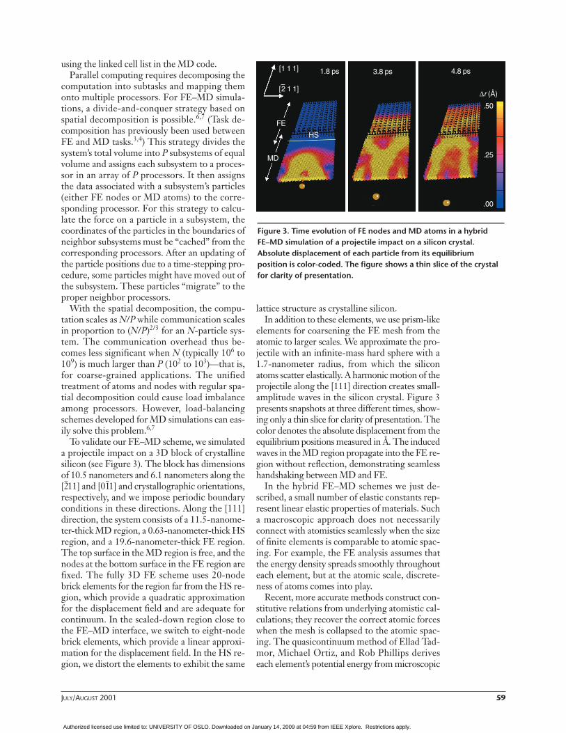
To validate our FE–MD scheme, we simulateda projectile impact on a 3D block of crystallinesilicon (see Figure 3). The block has dimensionsof 10.5 nanometers and 6.1 nanometers along the[2–11] and [01
–1] and crystallographic orientations,
respectively, and we impose periodic boundaryconditions in these directions. Along the [111]direction, the system consists of a 11.5-nanome-ter-thick MD region, a 0.63-nanometer-thick HSregion, and a 19.6-nanometer-thick FE region.The top surface in the MD region is free, and thenodes at the bottom surface in the FE region arefixed. The fully 3D FE scheme uses 20-nodebrick elements for the region far from the HS re-gion, which provide a quadratic approximationfor the displacement field and are adequate forcontinuum. In the scaled-down region close tothe FE–MD interface, we switch to eight-nodebrick elements, which provide a linear approxi-mation for the displacement field. In the HS re-gion, we distort the elements to exhibit the same
lattice structure as crystalline silicon.In addition to these elements, we use prism-like
elements for coarsening the FE mesh from theatomic to larger scales. We approximate the pro-jectile with an infinite-mass hard sphere with a1.7-nanometer radius, from which the siliconatoms scatter elastically. A harmonic motion of theprojectile along the [111] direction creates small-amplitude waves in the silicon crystal. Figure 3presents snapshots at three different times, show-ing only a thin slice for clarity of presentation. Thecolor denotes the absolute displacement from theequilibrium positions measured in Å. The inducedwaves in the MD region propagate into the FE re-gion without reflection, demonstrating seamlesshandshaking between MD and FE.
In the hybrid FE–MD schemes we just de-scribed, a small number of elastic constants rep-resent linear elastic properties of materials. Sucha macroscopic approach does not necessarilyconnect with atomistics seamlessly when the sizeof finite elements is comparable to atomic spac-ing. For example, the FE analysis assumes thatthe energy density spreads smoothly throughouteach element, but at the atomic scale, discrete-ness of atoms comes into play.
Recent, more accurate methods construct con-stitutive relations from underlying atomistic cal-culations; they recover the correct atomic forceswhen the mesh is collapsed to the atomic spac-ing. The quasicontinuum method of Ellad Tad-mor, Michael Ortiz, and Rob Phillips deriveseach element’s potential energy from microscopic
Figure 3. Time evolution of FE nodes and MD atoms in a hybridFE–MD simulation of a projectile impact on a silicon crystal.Absolute displacement of each particle from its equilibriumposition is color-coded. The figure shows a thin slice of the crystalfor clarity of presentation.
[1 1 1]
[–2 1 1]
1.8 ps
FE
MD
HS
.50
.25
.00
4.8 ps
∆r (Å)
3.8 ps
Authorized licensed use limited to: UNIVERSITY OF OSLO. Downloaded on January 14, 2009 at 04:59 from IEEE Xplore. Restrictions apply.

60 COMPUTING IN SCIENCE & ENGINEERING
interatomic potentials.8 This method assigns arepresentative crystallite in each element. It thendeforms the crystallite according to the local de-formation inside the element and assigns thecrystallite’s total energy to the element. RobertRudd and Jeremy Broughton’s coarse-grainedMD method derives constitutive relations forcontinuum directly from the interatomic poten-tial by means of a statistical coarse graining pro-cedure.4 For the actual atomic configurationwithin the elements, their method calculates thedynamical matrix and transforms it to an equiv-alent dynamical matrix for the nodes. Foratomic-size elements, the atomic and nodal de-grees of freedom are equal in number and theyobtain the MD dynamics. For large elements,they recover the continuum elasticity equationsof motion. This method constitutes a perfectlyseamless coupling of length scales but has highcomputational complexity.
Hybrid MD–QM schemesEmpirical interatomic potentials used in MD
simulations fail to describe chemical processes.Instead, to calculate interatomic interaction inreactive regions, we need a QM method that candescribe bond breakage and formation. Interesthas grown in developing hybrid MD–QM simu-lation schemes in which a reactive region treatedby a QM method is embedded in a classical sys-tem of atoms interacting through an empiricalinteratomic potential.
An atom consists of a nucleus and surround-ing electrons, and QM methods treat electronicdegrees of freedom explicitly, thereby describ-ing the wave-mechanical nature of electrons.One of the simplest QM methods is based ontight binding.3,4 TB does not involve electronicwave functions explicitly but solves an eigenvalueproblem for the matrix that represents interfer-ence between electronic orbitals. The spectrumof the eigenvalues gives the information on elec-tronic density of states. TB derives the electroniccontribution to interatomic forces through theHelmann-Feynman theorem, which states thatonly partial derivatives of the matrix elementswith respect to rN contribute to forces.
A more accurate but compute-intensive QMmethod deals explicitly with electronic wavefunctions,
(Nwf is the number of independent wave func-tions, or electronic bands, in the QM calcula-
tion), and their mutual interaction in the frame-work of the density functional theory9,10 and elec-tron–ion interaction using pseudopotentials.11
The DFT (for the development of which WalterKohn received a 1998 Nobel chemistry prize)reduces the exponentially complex quantummany-body problem to a self-consistent eigen-value problem that can be solved with O(N 3
wf)operations. With DFT, we can not only obtainaccurate interatomic forces from the Helmann-Feynman theorem, but also calculate electronicinformation such as charge distribution.
The quantum-chemistry community has ex-tensively developed hybrid MD–QM schemes.12
Various hybrid schemes combining both a mol-ecular orbital method with varying degrees ofquantum accuracy and a classical molecular me-chanics method simulate chemical and biologicalprocesses in solution. The hybrid MO–MMschemes usually terminate a dangling-bond arti-fact at the MO–MM boundary by introducing ahydrogen (H) atom in the MO calculation. Thehybrid simulation approach of Abraham and hiscolleagues uses a semiempirical TB method as aQM method and introduces an HS Hamiltonianto link the MD–TB boundary.3,4
Markus Eichinger and his colleagues have de-veloped a hybrid MD–QM scheme based on theDFT for simulating biological molecules in acomplex solvent.13 This scheme uses planewaves11 as the basis to solve the Kohn-Shamequations9 in the DFT. Such a plane-wave-basedscheme, however, is difficult to implement forthousands of atoms on massively parallel com-puters, because it uses the fast Fourier transform,which involves considerable communicationoverhead.
Recent efficient parallel implementations ofDFT calculations represent wave functions andpseudopotentials on uniform real-space meshpoints in Cartesian coordinates.14,15 These im-plementations perform the calculations in realspace using orthogonal basis functions and ahigh-order finite difference method. The multi-grid method can further accelerate real-spaceDFT calculations.15 Spatial-decomposition-based parallel implementation of the real-spacemethods is straightforward; systems containing afew thousand atoms can be simulated quantum-mechanically on 100 to 1,000 processors.
We have developed a hybrid scheme for dy-namic simulations of materials on parallel com-puters that embeds a QM region in an atomisticregion.16 A real-space multigrid-based DFT14,15
describes the motion of atoms in the QM region,
Ψ Ψ Ψ ΨN
Nwf
wfr r r r( ) = ( ) ( ) ( ){ }1 2, , ,K
Authorized licensed use limited to: UNIVERSITY OF OSLO. Downloaded on January 14, 2009 at 04:59 from IEEE Xplore. Restrictions apply.

JULY/AUGUST 2001 61
and the MD method describes it in the sur-rounding region. To partition the total systeminto the cluster and its environmental regions,we use a modular approach based on a linearcombination of QM and MD potential energies.
This approach consequently requires minimalmodification of existing QM and MD codes:12
where ECLsystem is the classical semiempirical po-
tential energy for the whole system and the lasttwo terms encompass the QM correction to thatenergy. EQM
cluster is the QM energy for an atomiccluster cut out of the total system (its danglingbonds are terminated by hydrogen atoms—handshake H’s). ECL
cluster is the semiempirical po-tential energy of a classical cluster that replaceshandshake H’s with appropriate atoms.
This approach requires calculating both QMand MD potential energies for the cluster. It in-troduces termination atoms in both calculationsfor the cluster. A unique scaled-position methodtreats HS atoms linking the cluster and the en-vironment. This method determines the posi-tions of HS atoms as functions of the originalatomic positions in the system. Different scalingparameters in the QM and classical clusters re-late the HS atoms to the termination atoms.
We implement our hybrid scheme on mas-sively parallel computers by first dividing proces-sors into the QM and the MD calculations (taskdecomposition) and then using spatial decom-position in each task. The parallel program isbased on message passing and follows the Mes-sage Passing Interface standard.17 We first placeprocessors into MD and QM groups by defin-ing two MPI communicators. (A communicator isan MPI data structure that represents a dynamicgroup of processes with a unique ID called con-text.) We write the code in the single-program,multiple-data (SPMD) programming style, sothat each processor executes an identical pro-gram. We use selection statements for the QMand the MD processors to execute only the QMand the MD code segments, respectively. To re-duce the memory size, we use dynamic memoryallocation and deallocation operations in For-tran 90 for all the array variables.
Figure 4 shows a flowchart of the parallelcomputations. First, spatial decomposition de-composes the total system into subdomains, eachof which is mapped onto an MD processor. TheMD processors calculate the classical potentialenergy, ECL
system, and corresponding atomic forces,
using an empirical interatomic potential. Sec-ond, atomic data for the cluster and the HSatoms that are necessary to create the H-termi-nated cluster are transferred to the QM proces-sors. Third, the QM processors perform DFTcalculations to obtain EQM
cluster and atomic forcesfor the H-terminated cluster, while the MDprocessors calculate ECL
cluster and atomic forces forthe classically terminated cluster, using the em-pirical interatomic potential. The real-spacemultigrid-based DFT code is parallelized by de-composing the mesh points to subdomains andthen distributing them into the QM processors.The MD processors collect the energy and forcesfrom QM and MD calculations. Finally, the MDprocessors calculate the total potential energy, E,and atomic forces, which in turn are used for timeintegration of the motion equations to updateatomic positions and velocities.
We applied the hybrid MD–QM simulationcode to oxidation of a silicon surface. Figure 5shows snapshots of the atomic configuration at50 and 250 femtoseconds; atomic kinetic ener-gies are color-coded. We see that dissociationenergy released at the reaction of an oxygen
E E E E= + −CLsystem
QMcluster
CLcluster
Update atomic positionsand velocities
MD–FE
Initial atomic positionsand velocities
QM nodes
Calculate classical forces(FCL,i )in the system
Calculate classical forces(FCL,i )in the cluster
Calculate total forces in the system: (Fi = FCL,i + FQM,i – FCL,i )
system
cluster
system clustercluster
Last step?No
Cluster data
(FQM,i )cluster
Calculatequantum-mechanical
forces (FQM,i )in the cluster
cluster
Figure 4. A flowchart of the parallel computations in our hybridFE–MD–QM simulation algorithm.
Authorized licensed use limited to: UNIVERSITY OF OSLO. Downloaded on January 14, 2009 at 04:59 from IEEE Xplore. Restrictions apply.

62 COMPUTING IN SCIENCE & ENGINEERING
molecule with silicon atoms in the cluster regiontransfers seamlessly to silicon atoms in the envi-ronment region.
Owing to the formal similarity between par-allel MD and FE–MD codes and the modular-ity of the MD–QM scheme, embedding a QMsubroutine in a parallel FE–MD code to developa parallel FE–MD–QM program is straightfor-ward, as Figure 4 shows.
Scalable FE–MD–QM algorithmsThe FE scheme calculates the force element-
by-element. And, with the lumped-mass approx-imation, it performs temporal propagation node-by-node with O(Nnode) operations in a highlyscalable manner (Nnode is the number of FEnodes). Atomistic study of process zones includ-ing mesoscale processes (dislocations and grains)requires that the MD region covers length scales
on the order of a micron ( N ~ 109 atoms); suchlarge-scale MD simulations require highly scal-able algorithms. Currently, the most serious bot-tleneck for large-scale FE–MD–QM simulationsis the computational complexity of QM calcula-tions. To investigate collective chemical reactionsat oxidation fronts or at frictional interfaces, theQM region must cover length scales of 1 to 10nanometers (approximately 103 to 104 atoms).Embedding a 104-atom QM calculation in 109-atom MD is only possible with scalable algo-rithms for both MD and QM simulations.
We have developed a suite of scalable MD andQM algorithms for materials simulations.18 Ourscalable parallel MD algorithms employ multi-resolutions in both space and time.6 We formu-late the DFT calculation as a minimization ofthe energy, EQM(rN, ψNwf) with respect to ψNwf,with orthonormalization constraints among theelectron wave functions, which is conventionallysolved by O(N 3
wf) operations.Researchers have proposed several O(Nwf)
DFT methods based on a real-space grid.19
These methods constrain each one-electron wavefunction in a local region and avoid orthogonal-ization of wave functions. We use the energy-functional minimization approach, which re-quires neither explicit orthogonalization norinversion of an overlap matrix but instead in-volves unconstrained minimization of a modifiedenergy function. Because the wave functions arelocalized in this approach, each wave function in-teracts with only those in the overlapping localregions. In each MD step, the conjugate-gradient(CG) method iteratively minimizes the energyfunction. Because the energy-minimization loopcontains neither a subspace diagonalization northe Gram-Schmidt orthonormalization, thecomputation time scales as O(Nwf/P) on P proces-sors. The communication data size betweenneighboring nodes to calculate the kinetic-energyoperator scales as O((Nwf/P)2/3) in the linear-scaling DFT algorithm, which is in contrast tothe O(Nwf(Nwf/P)2/3) communication in the con-ventional DFT algorithm. Global communica-tion for calculating overlap integrals of the wavefunctions, which scales as N 2
wf logP in the con-ventional DFT algorithm, is unnecessary in thelinear-scaling algorithm.
Figure 6 shows the computation time as afunction of the number of simulated atoms forour linear-scaling MD and DFT algorithms on1,024 IBM SP3 processors at the Naval Oceano-graphic Office Major Shared Resource Center.(For the DFT algorithm, we assume that each
Figure 5. A hybrid MD–QM simulation of oxidation of a silicon(100) surface. In the (a) initial configuration, magenta spheres arethe cluster silicon atoms, gray spheres are the environment siliconatoms, yellow spheres are termination hydrogen atoms for QM calculations, blue spheres are termination silicon atoms for MD calculations, and green spheres are cluster oxygen atoms. In thesnapshots at (b) 50 and (c) 250 femtoseconds, colors represent the kinetic energies of atoms in Kelvin.
(a)
(b) (c)
Authorized licensed use limited to: UNIVERSITY OF OSLO. Downloaded on January 14, 2009 at 04:59 from IEEE Xplore. Restrictions apply.

JULY/AUGUST 2001 63
MD step requires three self-consistent iterationsof the Kohn-Sham equations9 with 40 CG iter-ations per self-consistent iteration. To simulategallium arsenide systems, the DFT calculationsinclude two independent electron wave func-tions per atom.) The figure shows that the com-putation involved in both the MD and DFT al-gorithms scales linearly with the number ofatoms. The largest simulations include an 6.44-billion-atom silica system for MD and a111,000-atom gallium arsenide system for QM.Communication time in these calculations isnegligible compared with computation time.
Figure 6 also shows computation time for avariable-charge MD algorithm.20,21 This semi-empirical approach allows the study of certainchemical reactions such as oxidation with muchless computational complexity than with theDFT. This approach determines atomic chargesat every MD step to equalize electronegativitiesof all the atoms. Considering the long compu-tation time of the DFT algorithm comparedwith MD in Figure 6, such computationally lessdemanding semiempirical approaches to incor-porating chemical reactions in multiscale simu-lations continue to be important.
Immersive and interactivevisualization
The large-scale multiscale simulations we’vediscussed will generate enormous quantities ofdata. For example, a billion-atom MD simulationproduces 100 Gbytes of data per frame includingatomic species, positions, velocities, and stresses.Interactive exploration of such large datasets isimportant for identifying and tracking atomicfeatures that cause macroscopic phenomena. Im-mersive and interactive virtual environments arean ideal platform for such explorative visualiza-tion. We are designing algorithms to visualizelarge-scale atomistic simulations in 3D immer-sive and interactive virtual environments. Ourapproach employs adaptive and hierarchical datastructures for efficient visibility culling and levels-of-detail control for fast rendering.
To achieve interactive-walkthrough speed andlow access times in billion-atom systems, we em-ploy an octree data structure and extract the re-gions of interest at runtime, thereby minimizingthe size of the data sent to the rendering system(see Figure 7).22 We obtain the octree data struc-ture by recursively dividing the physical systeminto smaller cells. We use standard visibility-culling algorithms to extract only the atoms that
fit in the viewer’s field of view.The rendering algorithm uses a configurable
multiresolution scheme to improve the walk-through experience’s performance and visual ap-peal. This scheme individually draws eachatomic entity at resolutions ranging from a pointto a sphere, using from eight to 1,000 polygonsfor each entity. An OpenGL display list (a fastand convenient way to organize a set ofOpenGL commands) for each type of atom isgenerated at all possible resolutions, because itis more efficient than individual function calls.At runtime, a particular resolution is called foreach atom on the basis of the distance betweenthe viewer and object.
To accelerate the rendering and scene update,we use textures. We employ
• billboarding for displaying the atoms and• large texture maps to increase the depth.
Theoretically, these techniques will decrease thenumber of polygons to be displayed. However,accounting for the user perspective requires ad-ditional calculations. This can involve situationswhere slight changes in the user view make cer-tain objects visible.
Figure 6. The computation time of MD and QMalgorithms on 1,024 IBM SP3 processors. The figure shows wall clock time as a function of thenumber of atoms for three linear-scalingschemes: classical MD of silica based on many-body interatomic potentials (circles);environment-dependant, variable-charge MD ofalumina (squares); and a self-consistent QMscheme based on the DFT (triangles). Lines showideal linear-scaling behaviors.
Wal
l clo
ck ti
me
(sec
onds
per
MD
ste
p)
Authorized licensed use limited to: UNIVERSITY OF OSLO. Downloaded on January 14, 2009 at 04:59 from IEEE Xplore. Restrictions apply.

64 COMPUTING IN SCIENCE & ENGINEERING
We have implemented this system in an Imm-ersaDesk virtual environment (see Figure 8).The ImmersaDesk consists of a pivotal screen,an Electrohome Marquee stereoscopic projec-tor, a head-tracking system, an eyewear kit, in-frared emitters, a wand with a tracking sensor,and a wand-tracking I/O subsystem. A pro-grammable wand with three buttons and a joy-stick allows interactions between the viewer andsimulated objects. The rendering system is anSGI Onyx with two R10000 processors, 4Gbytes of system RAM, and an InfinityReality2graphics pipeline; it can render walkthroughs ofmultimillion-atom systems. However, it cannothandle multibillion-atom systems. For visualiza-tion at such large scales, we are exploring paral-lel processing on a cluster of PCs for data man-agement and dedicating the SGI system torendering. A scheme that predicts the user’s nextmovement and prefetches data from the clusterwould also be advantageous.
Modern MD simulations of materi-als started in 1964 when AneesurRahman simulated 864 argonatoms on a CDC 3600 com-
puter.23 Assuming a simple exponential growth,the number of atoms that classical MD simula-tions can handle has doubled every 19 monthsto reach 6.44 billion atoms. Similarly, the num-ber of atoms in DF–MD simulations (started byRoberto Car and Michelle Parrinello in 1985 foreight silicon atoms) has doubled every 12months to 111,000.
In the next 10 years, petaflop computers willmaintain the growth rates in these “MD Moore’slaws,” and we will be able to perform 1012-atomclassical and 107-atom quantum MD simula-tions. Multiresolution approaches, combinedwith cache-conscious techniques, will be essen-tial to achieve scalability on petaflop architec-tures. Ingenious use of multiscale FE–MD–QMsimulations implemented with such scalable al-
Figure 7. An octree data structure for culling. Octree cells (bounded by white lines) dynamically approximate the currentvisible region (the arrow represents the viewer’s position and viewing direction). Only the visible atoms are processedfor rendering.
Authorized licensed use limited to: UNIVERSITY OF OSLO. Downloaded on January 14, 2009 at 04:59 from IEEE Xplore. Restrictions apply.

JULY/AUGUST 2001 65
gorithms will play a significant role in nanoscalematerials research.
However, many problems remain. For exam-ple, ill-conditioned minimization prohibits thepractical application of current linear-scalingDFT algorithms.19 This is due to the localiza-tion approximation that destroys the invarianceof the energy under unitary transformations ofthe wave functions. Designing a scalable libraryof well-conditioned, fast FE–MD–QM algo-rithms that work for a wide range of applicationswill be one of the most exciting challenges incomputational science and engineering in thenext 10 years.
AcknowledgmentsWe carried out parts of the research presented in this ar-ticle in collaboration with Xinlian Liu, Paul Miller, andAshish Sharma at Louisiana State University and DeAn-dra Hayes at Xavier University. We thank Leslie F. Green-gard, S. Lennart Johnsson, Efthimios Kaxiras, Pramod P.Khargonekar, Wolfgang G. Knauss, Peter A. Kollman,Anupam Madhukar, Krishnaswamy Ravi-Chandar, Vik-tor K. Prasanna, James R. Rice, and Robert O. Ritchie forstimulating discussions. This work is partially supportedby the Air Force Office of Scientific Research, the Depart-ment of Energy, NASA, the National Science Foundation,and the USC-LSU Multidisciplinary Research Program ofthe University Research Initiative. We performed somemillion-atom simulations using in-house parallel com-puters at LSU’s Concurrent Computing Laboratory forMaterials Simulations. We performed 10-million- to bil-lion-atom simulations using parallel computers at the De-partment of Defense’s Major Shared Resource Centersunder a DoD Challenge project.
References1. M.C. Roco, S. Williams, and P. Alivisatos, eds., Nanotechnology
Research Directions: IWGN Workshop Report, World TechnologyDivision, Int’l Technology Research Inst., Loyola College, Bal-timore, 1999, http://itri.loyola.edu/nano/IWGN.Research.Directions (current 21 May 2001).
2. A. Pechenik, R.K. Kalia, and P. Vashishta, Computer-Aided Designof High-Temperature Materials, Oxford Univ. Press, Oxford, UK,1999.
3. F.F. Abraham et al., “Spanning the Length Scales in DynamicSimulation,” Computers in Physics, vol. 12, 1998, pp. 538–546.
4. R.E. Rudd and J.Q. Broughton, “Concurrent Coupling of LengthScales in Solid State Systems,” Physica Status Solidi B, vol. 217,2000, pp. 251–291.
5. P. Vashishta et al., “Molecular Dynamics Methods and Large-Scale Simulations of Amorphous Materials,” Amorphous Insula-tors and Semiconductors, M.F. Thorpe and M.I. Mitkova, eds.,Kluwer Academic Publishers, Dordrecht, Netherlands, 1996, pp.151–213.
6. A. Nakano, R.K. Kalia, and P. Vashishta, “Scalable Molecular-Dynamics, Visualization, and Data-Management Algorithms forMaterials Simulations,” Computing in Science & Eng., vol. 1, no. 5,Sept./Oct. 1999, pp. 39–47.
7. A. Nakano, “Multiresolution Load Balancing in Curved Space:The Wavelet Representation,” Concurrency: Practice and Experi-ence, vol. 11, 1999, pp. 343–353.
8. E.B. Tadmor, M. Ortiz, and R. Phillips, “Quasicontinuum Analysisof Defects in Solids,” Philosophical Magazine A, vol. 73, 1996, pp.1529–1563.
9. P. Hohenberg and W. Kohn, “Inhomogeneous Electron Gas,”Physical Rev., vol. 136, 1964, pp. B864–B871.
10. R. Car and M. Parrinello, “Unified Approach for Molecular Dy-namics and Density Functional Theory,” Physical Rev. Letters, vol.55, 1985, pp. 2471–2474.
11. M.C. Payne et al., “Iterative Minimization Techniques for Ab Ini-tio Total Energy Calculations: Molecular Dynamics and Conju-gate Gradients,” Rev. Modern Physics, vol. 64, 1992, pp.1045–1097.
12. S. Dapprich et al., “A New ONIOM Implementation in Gaussian98: I. The Calculation of Energies, Gradients, Vibrational Fre-quencies, and Electric Field Derivatives,” J. Molecular Structure:Theochem, vols. 461–462, 1999, pp. 1–21.
13. M. Eichinger et al., “A Hybrid Method for Solutes in ComplexSolvents: Density Functional Theory Combined with EmpiricalForce Fields,” J. Chemical Physics, vol. 110, 1999, pp.10452–10467.
14. J.R. Chelikowsky et al., “Electronic Structure Methods for Pre-dicting the Properties of Materials: Grids in Space,” Physica Sta-tus Solidi B, vol. 217, 2000, pp. 173–195.
Figure 8. A scientist immersed in an atomistic model of a fracturedceramic nanocomposite. This system is a silicon nitride ceramic matrix reinforced with silica-coated silicon carbide fibers. Smallspheres represent silicon atoms; large spheres represent nitrogen(green), carbon (magenta), and oxygen (cyan) atoms.
Authorized licensed use limited to: UNIVERSITY OF OSLO. Downloaded on January 14, 2009 at 04:59 from IEEE Xplore. Restrictions apply.

66 COMPUTING IN SCIENCE & ENGINEERING
15. J. Bernholc, “Computational Materials Science: The Era of Ap-plied Quantum Mechanics,” Physics Today, vol. 52, no. 9, 1999,pp. 30–35.
16. S. Ogata et al., “Hybrid Finite-Element/Molecular-Dynamics/Elec-tronic-Density-Functional Approach to Materials Simulations onParallel Computers,” to be published in Computer Physics Comm.
17. W. Gropp, E. Lusk, and A. Skjellum, Using MPI, 2nd ed., MITPress, Cambridge, Mass., 1994.
18. F. Shimojo et al., “A Scalable Molecular-Dynamics-AlgorithmSuite for Materials Simulations: Design-Space Diagram on 1,024Cray T3E Processors,” Future Generation Computer Systems, vol.17, 2000, pp. 279–291.
19. S. Goedecker, “Linear Scaling Electronic Structure Methods,”Rev. Modern Physics, vol. 71, 1999, pp. 1085–1123.
20. F.H. Streitz and J.W. Mintmire, “Electrostatic Potentials for Metal-Oxide Surfaces and Interfaces,” Physical Rev. B, vol. 50, 1994,pp. 11996–12003.
21. T.J. Campbell et al., “Dynamics of Oxidation of Aluminum Nano-clusters Using Variable Charge Molecular-Dynamics Simulationson Parallel Computers,” Physical Rev. Letters, vol. 82, 1999, pp.4866–4869.
22. D. Aliaga et al., “MMR: An Integrated Massive Model RenderingSystem Using Geometric and Image-Based Acceleration,” Proc.1999 ACM Symp. Interactive 3D Graphics, ACM Press, New York,1999, pp. 199–206.
23. A. Rahman, “Correlations in the Motion of Atoms in Liquid Ar-gon,” Physical Rev., vol. 136, no. 2A, 1964, pp. A405–A411.
Aiichiro Nakano is an associate professor of computerscience and a member of the Concurrent ComputingLaboratory for Materials Simulations and the Biologi-cal Computation and Visualization Center at LouisianaState University. He received his PhD in physics fromthe University of Tokyo. Contact him at the Dept. ofComputer Science, Coates Hall, Louisiana State Univ.,Baton Rouge, LA 70803-4020; [email protected];www.cclms.lsu.edu.
Martina E. Bachlechner, formerly with the Concur-rent Computing Laboratory for Materials Simulations,is an assistant professor of physics at West Virginia Uni-versity. She received her PhD in physics from JohannesKepler University in Austria. Contact her at the Dept.of Physics, Hodges Hall, West Virginia Univ., Morgan-town, WV 26507; [email protected].
Rajiv K. Kalia is a professor of physics and astronomyand of computer science at Louisiana State University.He is the director of LSU’s Biological Computation andVisualization Center and a cofounder, with PriyaVashishta, of the Concurrent Computing Laboratoryfor Materials Simulations. He received his PhD inphysics from Northwestern University. Contact him atthe Dept. of Physics & Astronomy, Nicholson Hall,Louisiana State Univ., Baton Rouge, LA 70803-4001;[email protected].
Elefterios Lidorikis is a postdoctoral researcher at theLouisiana State University’s Concurrent ComputingLaboratory for Materials Simulations and BiologicalComputation and Visualization Center. He received hisPhD in physics from Iowa State University. Contact himat the Dept. of Physics & Astronomy, Nicholson Hall,Louisiana State Univ., Baton Rouge, LA 70803-4001;[email protected].
Priya Vashishta is a Cray Research professor of com-putational sciences in the Departments of Physics &Astronomy and of Computer Science at LSU. He isthe director of LSU’s Concurrent Computing Labora-tory for Materials Simulations. He received his PhDin physics from the Indian Institute of Technology.Contact him at the Dept. of Physics & Astronomy,Nicholson Hall, Louisiana State Univ., Baton Rouge,LA 70803-4001; [email protected]. [email protected].
George Z. Voyiadjis is a Boyd Professor in the Depart-ment of Civil and Environmental Engineering atLouisiana State University. He is the director of LSU’sAdvanced Computational Solid Mechanics Laboratory.He received his D.Sc. in engineering mechanics fromColumbia University. Contact him at the Dept. of Civiland Environmental Eng., Louisiana State Univ., BatonRouge, LA 70803-6405; [email protected].
Timothy J. Campbell is a principal analyst at LogiconInformation Systems & Services and at the NavalOceanographic Office Major Shared Resource Center.He received his PhD in physics from Louisiana StateUniversity. Contact him at Logicon, NAVO MSRC PET,Bldg. 1103, Rm. 248, Stennis Space Center, MS39529; [email protected].
Shuji Ogata is an associate professor of applied physicsat Yamaguchi University, Japan. He received a PhD inphysics from the University of Tokyo, Japan. Contacthim at the Dept. of Applied Sciences, Yamaguchi Univ.,2-16-1 Tokiwadai, Ube 755-8611, Japan; [email protected].
Fuyuki Shimojo is a research associate in the Facultyof Integrated Arts and Sciences at Hiroshima Univer-sity, Japan, and a postdoctoral researcher at LouisianaState University’s Concurrent Computing Laboratoryfor Materials Simulations. He received his PhD inphysics from Niigata University, Japan. Contact him atthe Faculty of Integrated Arts and Sciences, HiroshimaUniv., Higashi-Hiroshima 739-8521, Japan; [email protected].
Authorized licensed use limited to: UNIVERSITY OF OSLO. Downloaded on January 14, 2009 at 04:59 from IEEE Xplore. Restrictions apply.


![ULTISCALE ODEL. SIMUL c - California Institute of …users.cms.caltech.edu/~owhadi/index_htm_files/SIAMMMS2010.pdf · diseasesasHuntington’sandAlzheimer’sandtypeIIdiabetes[45]](https://img.pdfslide.net/doc/110x75/5b5cbdaa7f8b9ad2198d0b2f/ultiscale-odel-simul-c-california-institute-of-userscms-owhadiindexhtmfilessiammms2010pdf.jpg)