Embed Size (px)
Citation preview
Ultra high frequency Nano Cantilevers g q y(NEMS)
Introduction
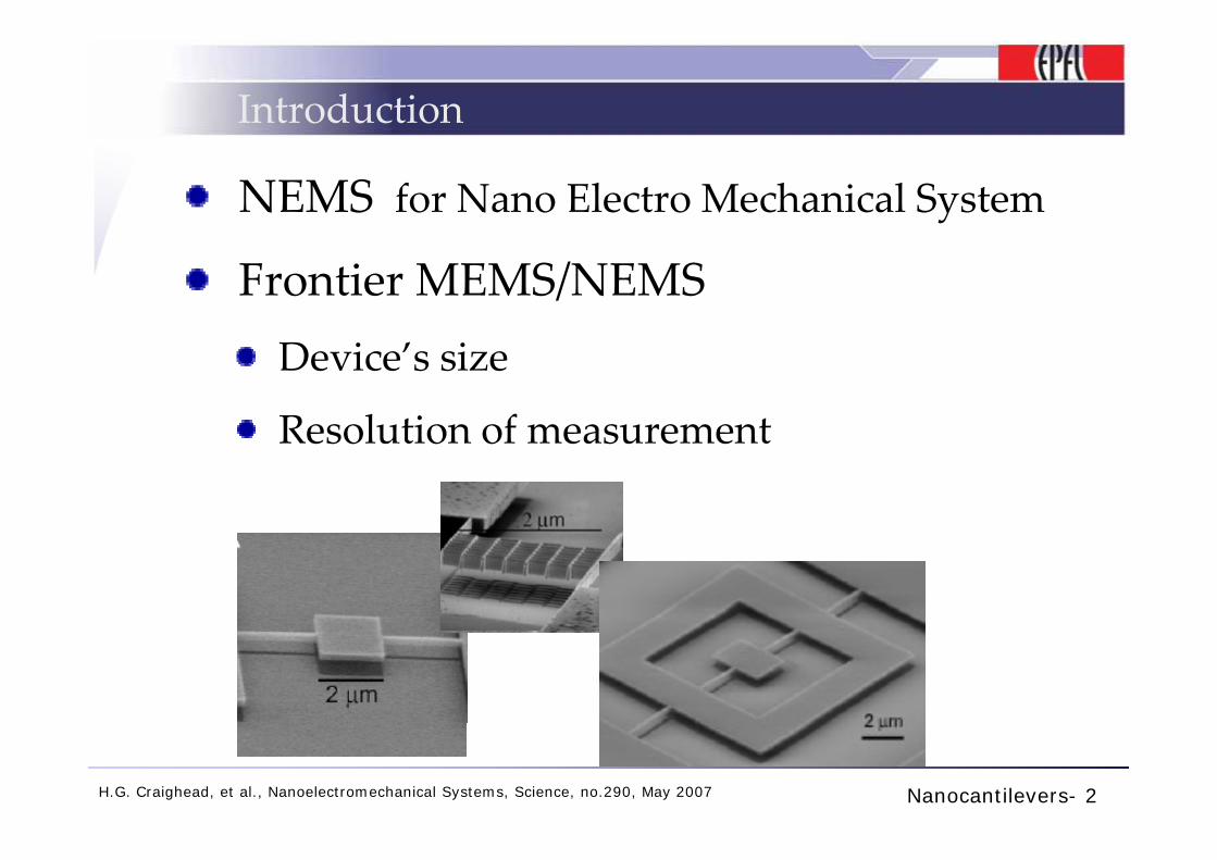
NEMS for Nano Electro Mechanical System
Frontier MEMS/NEMSDevice’s size
Resolution of measurementResolution of measurement
Nanocantilevers- 2H.G. Craighead, et al., Nanoelectromechanical Systems, Science, no.290, May 2007
Cantilevers (1)
MEMS/NEMS cantilevers
Applications:
Imaging (AFM, STM)Sensing (mass sensor gas detectionSensing (mass sensor, gas detection, molecular detection)
Nanocantilevers- 3
Cantilevers (2)
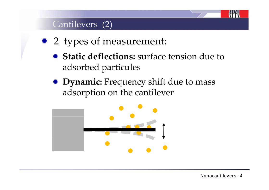
2 types of measurement:Static deflections: surface tension due to adsorbed particulesDynamic: Frequency shift due to mass adsorption on the cantileveradsorption on the cantilever
Nanocantilevers- 4

Cantilevers (3)
4 important factors to take in account for high performancefor high performance:1. Mechanical resonance frequency1. Mechanical resonance frequency
2. Sensitivity1. Mechanical element
2 Transducer2. Transducer
3. Quality factory
4. Resolution
TITLE- 5
Frequency resonance (1)
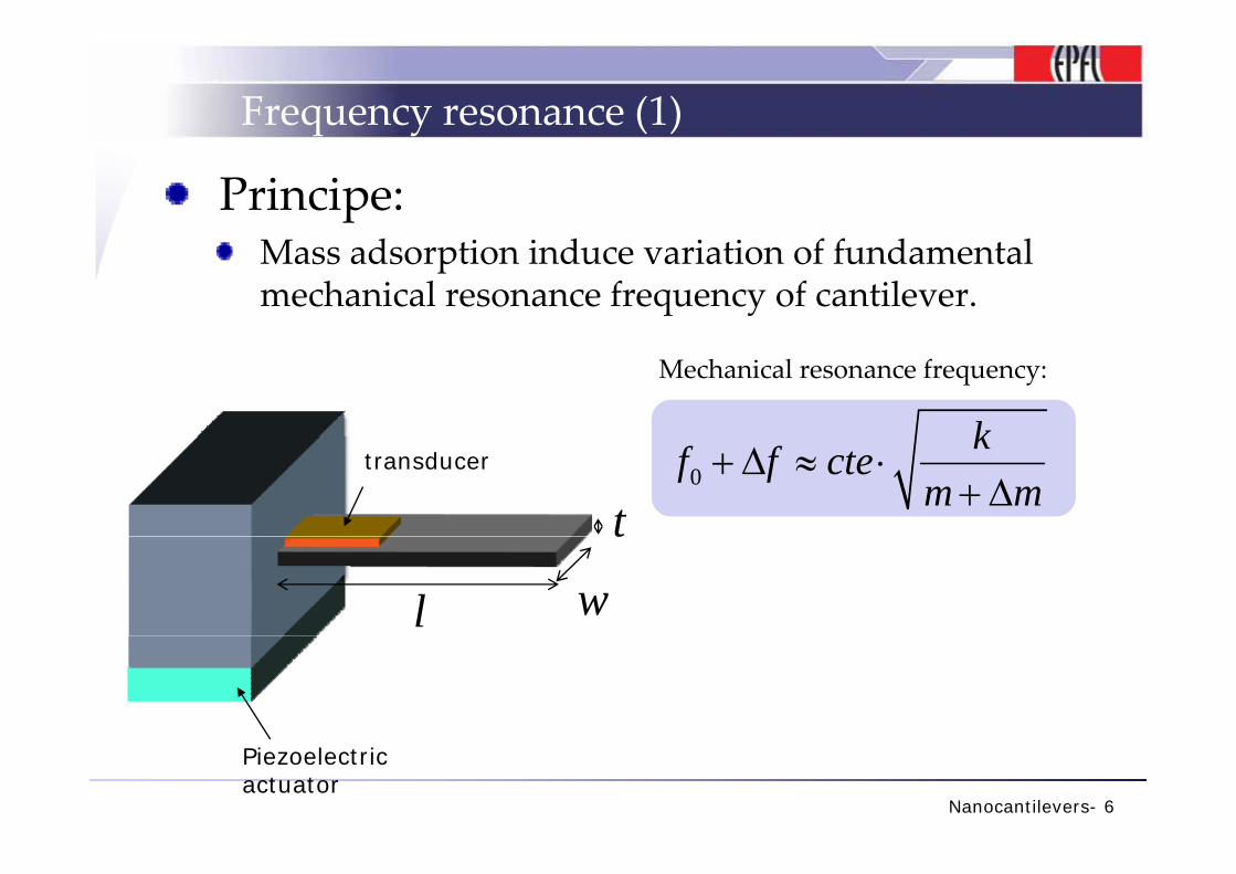
Principe:d d f f d lMass adsorption induce variation of fundamental
mechanical resonance frequency of cantilever.
k
Mechanical resonance frequency:
t0
kf f ctem m
+ Δ ≈ ⋅+ Δ
transducer
t
wl
Nanocantilevers- 6
Piezoelectric actuator
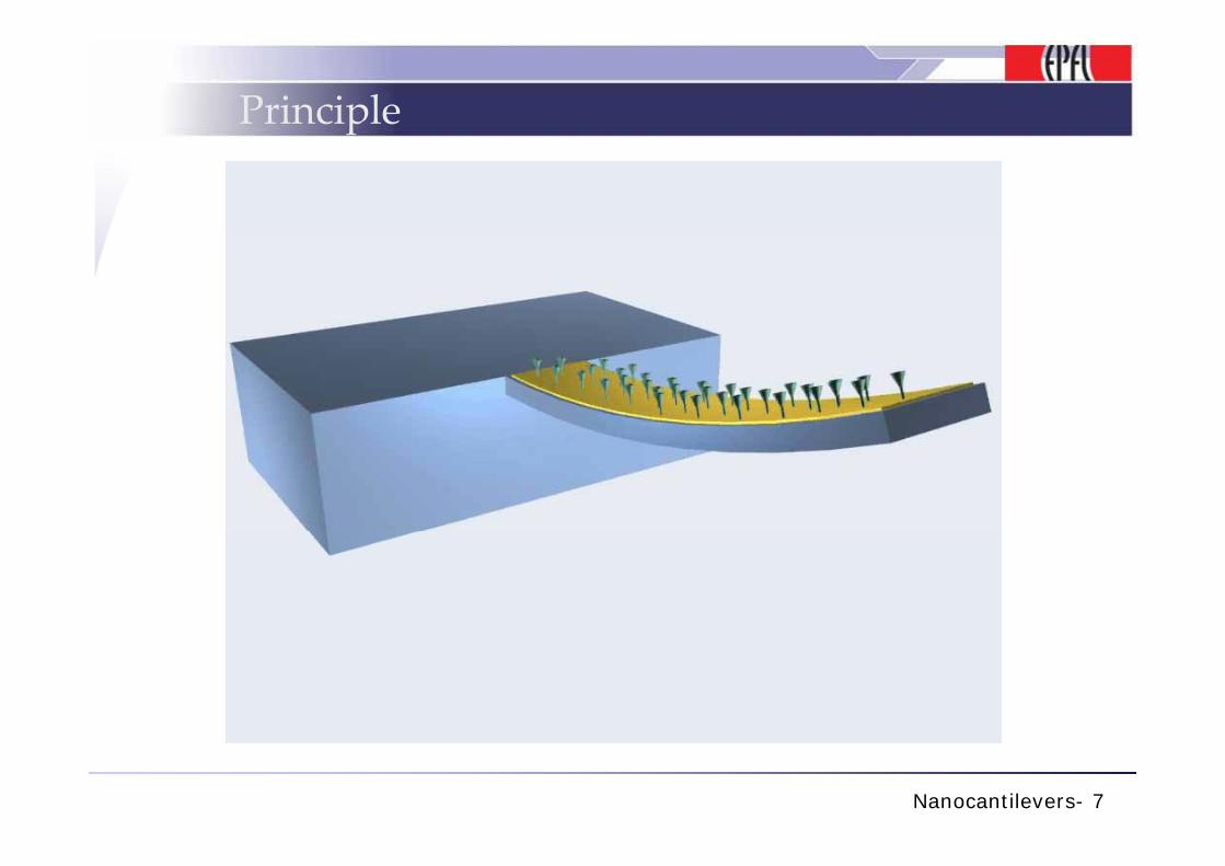
Principle
Nanocantilevers- 7
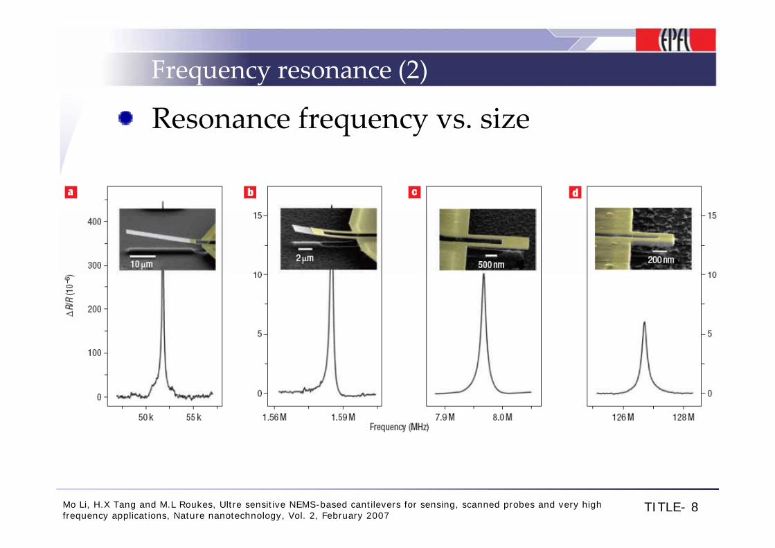
Frequency resonance (2)
Resonance frequency vs. size
TITLE- 8Mo Li, H.X Tang and M.L Roukes, Ultre sensitive NEMS-based cantilevers for sensing, scanned probes and very high frequency applications, Nature nanotechnology, Vol. 2, February 2007
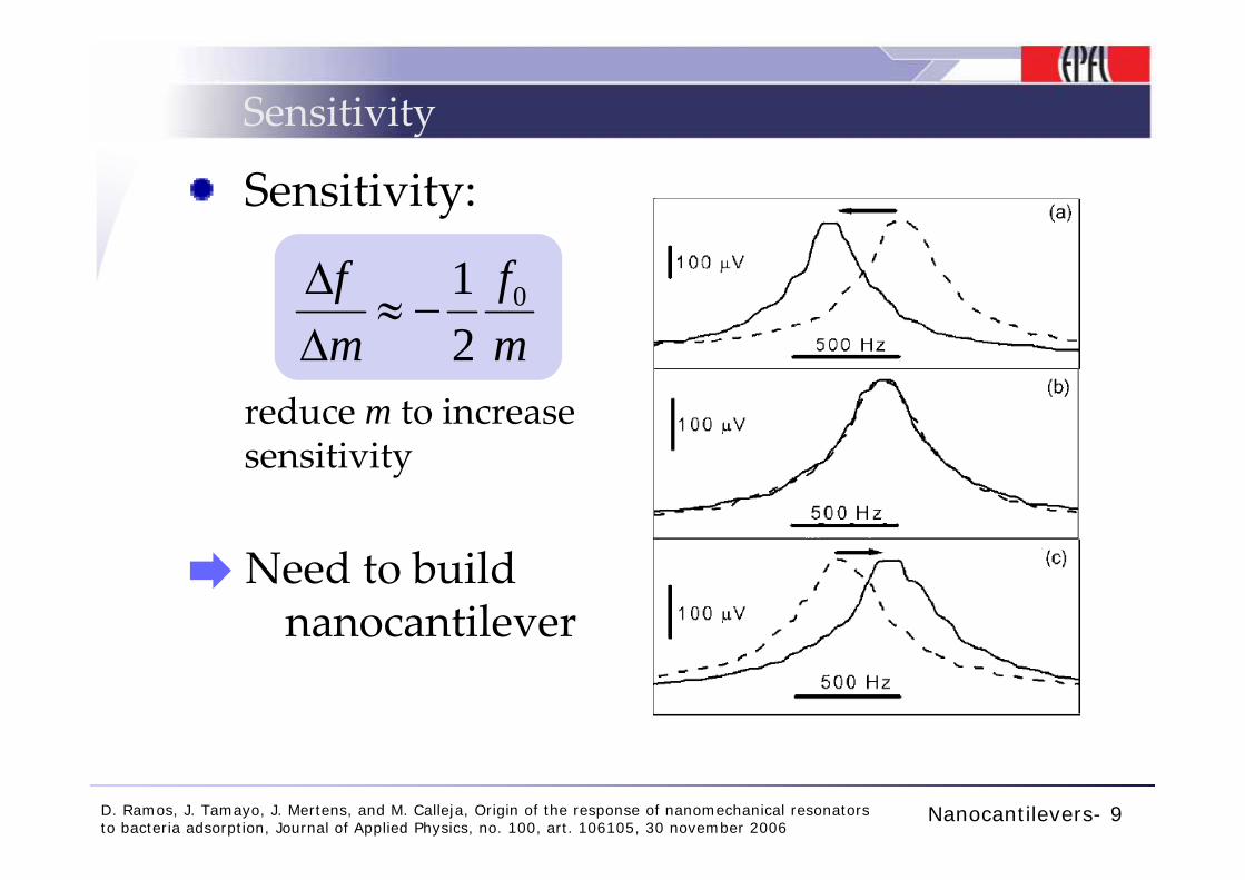
Sensitivity
Sensitivity:
012
ffm mΔ
≈ −Δ
reduce m to increase
2m mΔ
sensitivity
Need to build nanocantilever
Nanocantilevers- 9D. Ramos, J. Tamayo, J. Mertens, and M. Calleja, Origin of the response of nanomechanical resonators to bacteria adsorption, Journal of Applied Physics, no. 100, art. 106105, 30 november 2006
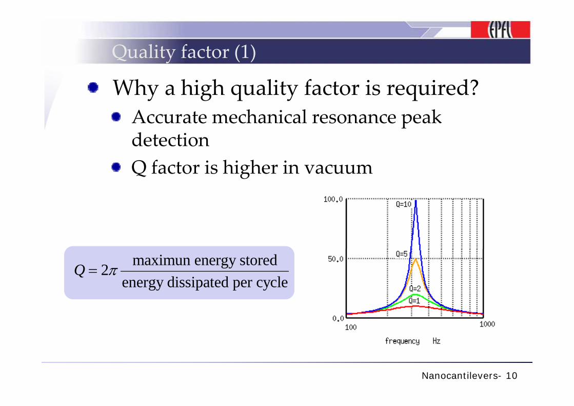
Quality factor (1)
Why a high quality factor is required?A h i l kAccurate mechanical resonance peak detectionQ factor is higher in vacuum
maximun energy stored2energy dissipated per cycle
Q π=
Nanocantilevers- 10
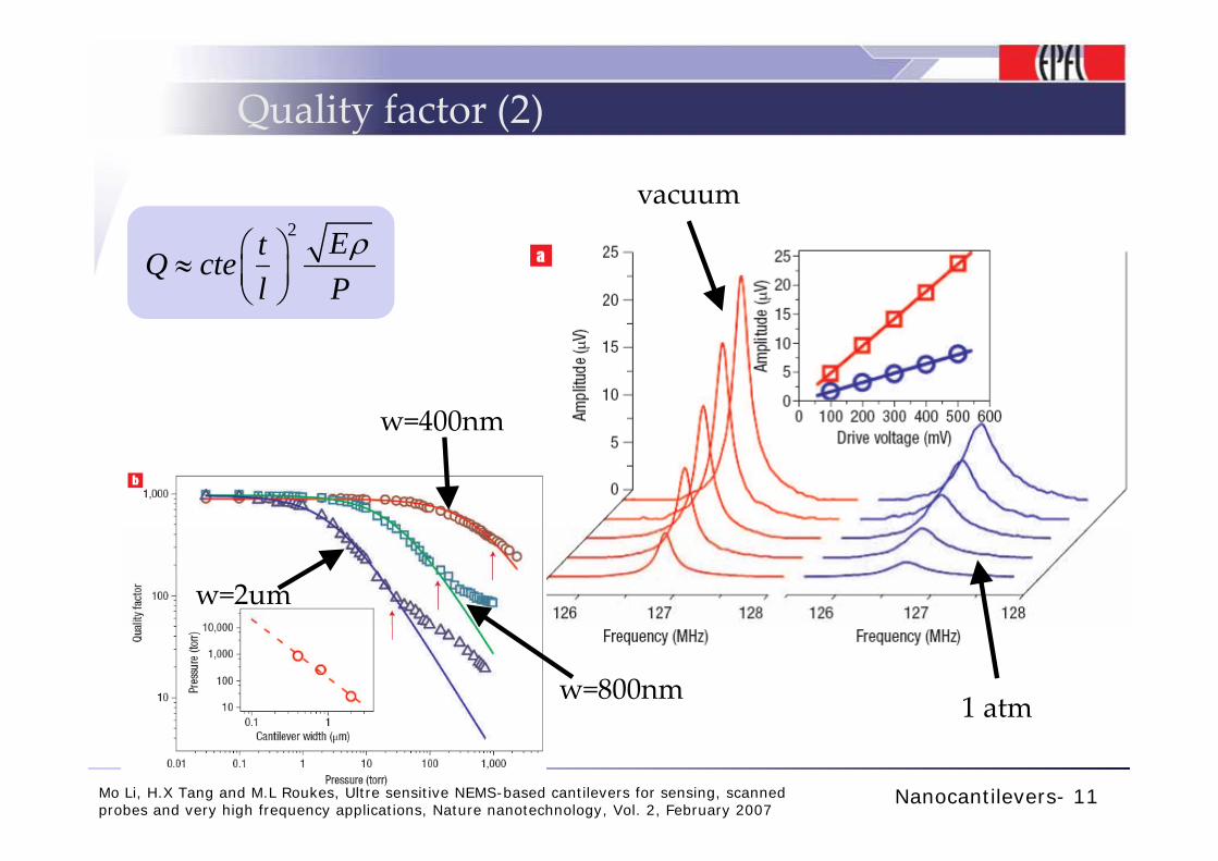
Quality factor (2)
2 E⎛ ⎞
vacuumvacuum2 EtQ cte
l Pρ⎛ ⎞≈ ⎜ ⎟
⎝ ⎠
w=400nm00
w=2um
1 atmw=800nm
Nanocantilevers- 11Mo Li, H.X Tang and M.L Roukes, Ultre sensitive NEMS-based cantilevers for sensing, scanned probes and very high frequency applications, Nature nanotechnology, Vol. 2, February 2007
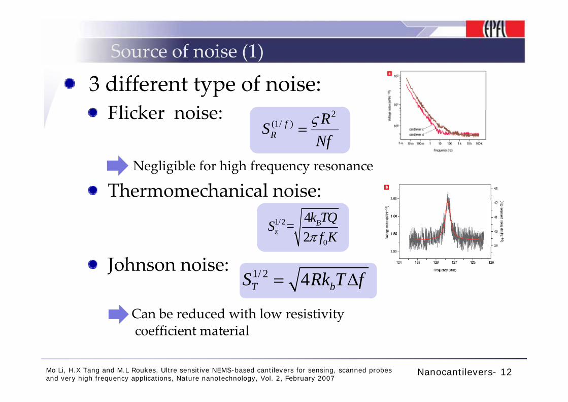
Source of noise (1)
3 different type of noise:Fli ke oi eFlicker noise: 2
(1/ )fR
RSNfς
=
Negligible for high frequency resonance
Thermomechanical noise:1/2
0
4=2
Bz
k TQSf Kπ
Johnson noise: 1/ 2 4T bS Rk T f= Δ
Can be reduced with low resistivitycoefficient material
Nanocantilevers- 12Mo Li, H.X Tang and M.L Roukes, Ultre sensitive NEMS-based cantilevers for sensing, scanned probes and very high frequency applications, Nature nanotechnology, Vol. 2, February 2007
Transducer (1)
Displacement transduction in NEMS:Optical
Diffraction effects problems appearsDiffraction effects problems appears
Capacitivep
Inadequate for nanoscale devices due to parasites effectsparasites effects
Piezoresistive
Integrated: Suitable for nanoscale devices !
Nanocantilevers- 13
Transducer(2)
Piezoresitive materials for transducers:Sensitivity:
with 20semiconductor metalR K K K
RεΔ
= ⋅ ≈ ⋅
But… 410semiconductor metalnoise noise≈ ⋅
The resolution is given by:
semiconductor metal
g ynoiseresolution
sensitivity=
metal semiconductorresolution resolution>>
Nanocantilevers- 14
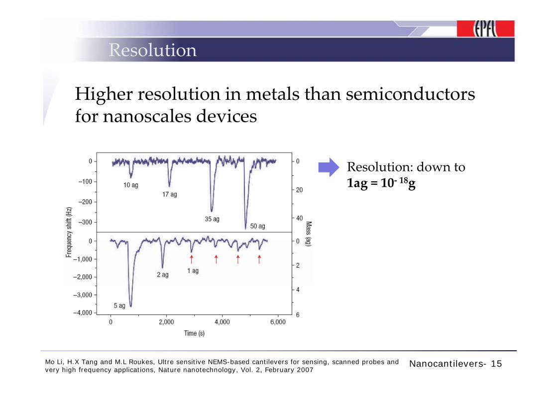
Resolution
Higher resolution in metals than semiconductors for nanoscales devices
Resolution: down to 1ag = 10‐ 18g
Nanocantilevers- 15Mo Li, H.X Tang and M.L Roukes, Ultre sensitive NEMS-based cantilevers for sensing, scanned probes and very high frequency applications, Nature nanotechnology, Vol. 2, February 2007
Conclusion
Increasing of performance can be achie ed byachieved by:
Higher frequency resonanceHigher frequency resonance
Low resistivity materials for transducer for nanoscales devicesEnhancement of nanofabricationEnhancement of nanofabrication techniques
Nanocantilevers- 16
Static Deflectionin Nanomechanical cantilevers
Nanotechnology Seminar
Gabriella Sinicco
Nanomechanics – Static Deflection- 2
Outline
• Introduction
• Nanomechanical cantilever
• What is static deflection?
• How does it work?
• Challenges
• Areas of interest
• Why does the cantilever bend?
• How to detect bending
• Applications
• Biomolecules recognition (advantages…)
• Artificial nose
• Conclusion
Nanomechanics – Static Deflection- 3
Introduction
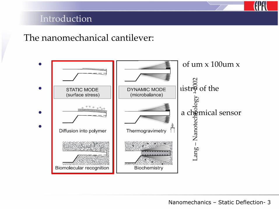
The nanomechanical cantilever:
• Thin flexible beam made of silicon (100 of um x 100um x
1um)
• Allows exploring the physics and chemistry of the
nanometer world
• Coated with a sensor layer, it serves as a chemical sensor
• Deflection is at nanometer scale
Lan
g –
Nan
ote
chn
olo
gy
-20
02
Nanomechanics – Static Deflection- 4
Introduction
What is static deflection?
• In “nanomechanics”:
bending of a nanomechanical cantilever due to the action of
a force
• The entity to be sensed will determine the force
• The entity is sensitive to the surface coating
Nanomechanics – Static Deflection- 5
Introduction
How does it work?
Nanomechanics – Static Deflection- 6
Introduction
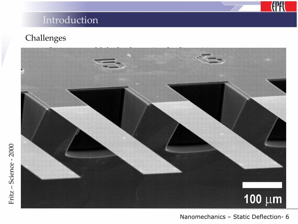
Challenges
• Improve sensitivity by decreasing the dimensions
• Selective bending of the cantilever allowing entity recognition and measurement
Motivations:
• No labeling needed for detection
• Easy and “cheap” production (Si technology)
• Can operate in air, vacuum, or liquid environments
• Fast analysis ( within some minutes)
• Cyclic operations after purging
• Arrays :
• Differential as well as simultaneous measurements
• Individual coating of each cantilever allows measurement of multiple substances within a mixture
Fri
tz –
Sci
ence
-20
00
Nanomechanics – Static Deflection- 7
Introduction
Areas of interest:
• Biochemical /medical analysis
• Gas sensing
• Quality control (food, chemicals, air)
• Fragrance design
• Oenology
• Forensic investigations
• Drugs and explosives detection
• Research
Nanomechanics – Static Deflection- 8
Bending origins
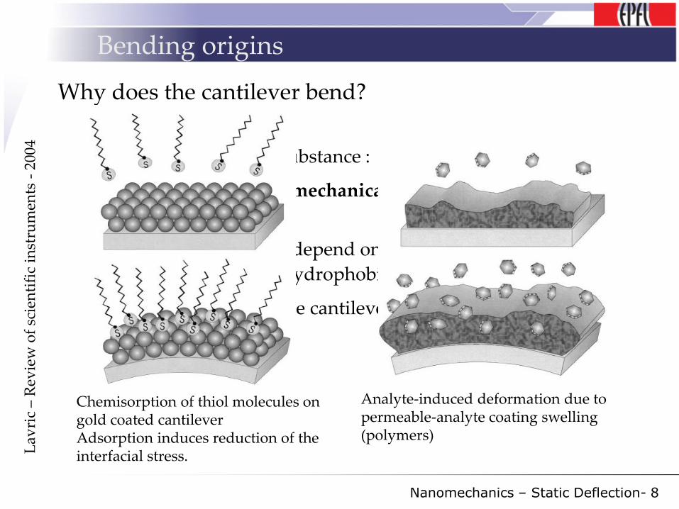
Why does the cantilever bend?
• Contact with target substance :
chemical reaction mechanical response: bending due to
surface stress
• Forces causing stress depend on entity at the surface
(electrostatic, steric, hydrophobic interactions …)
• Tiny dimensions of the cantilever extremely high
sensitivity.
Analyte-induced deformation due to permeable-analyte coating swelling (polymers)
Chemisorption of thiol molecules on gold coated cantileverAdsorption induces reduction of the interfacial stress.L
avri
c –
Rev
iew
of
scie
nti
fic
inst
rum
ents
-20
04
Nanomechanics – Static Deflection- 9
Detection of bending
How to detect bending
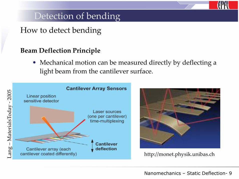
Beam Deflection Principle
• Mechanical motion can be measured directly by deflecting a
light beam from the cantilever surface.
Lan
g –
Mat
eria
lsT
od
ay -
2005
http://monet.physik.unibas.ch
Nanomechanics – Static Deflection- 10
Applications
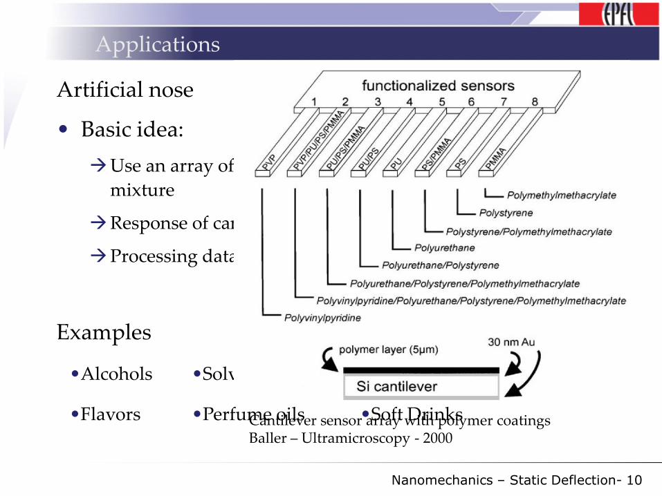
Artificial nose
• Basic idea:
Use an array of functionalized cantilevers and expose to
mixture
Response of cantilever characteristic for every mixture
Processing data allows to recognize the mixtures
Examples
•Alcohols •Solvents •Methanol/water mixtures
•Flavors •Perfume oils •Soft DrinksCantilever sensor array with polymer coatingsBaller – Ultramicroscopy - 2000
Nanomechanics – Static Deflection- 11
Applications
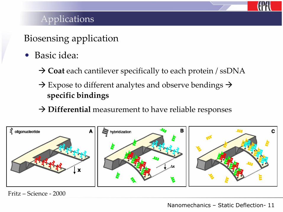
Biosensing application
• Basic idea:
Coat each cantilever specifically to each protein / ssDNA
Expose to different analytes and observe bendings
specific bindings
Differential measurement to have reliable responses
Fritz – Science - 2000
Nanomechanics – Static Deflection- 12
Conclusions
Current research:
• Improvements in reproducibility and sensitivity, and
integration of microfluidics and detection systems
Future trends :
• New fabrication methods to enhance cantilever
response : nanostructuration to increase surface area
• Portable biosensor microsystem for high-
throughput screening: integrate optical (or piezo-
resistive) read-out and micro fluidics
Nanomechanics – Static Deflection- 13
Key messages
• Sensing without labeling you save time
• Static deflection allows quantifying very small
quantities (nm deflections detectable ng/ml, nM
concentrations) very sensitive
• Versatile: can be operated in various environments
• Fast and reusable
SMFSSingle molecule force spectroscopy
Séminaire : Nanomechanics
DIA - 2
Principe
• Mesurer les forces de liaison au sein d’une molécule
• Mesure de la force à la rupture entre deux molécules (ex: anticorps - antigène)
• Propriétés mécaniques des molécules (élasticité)
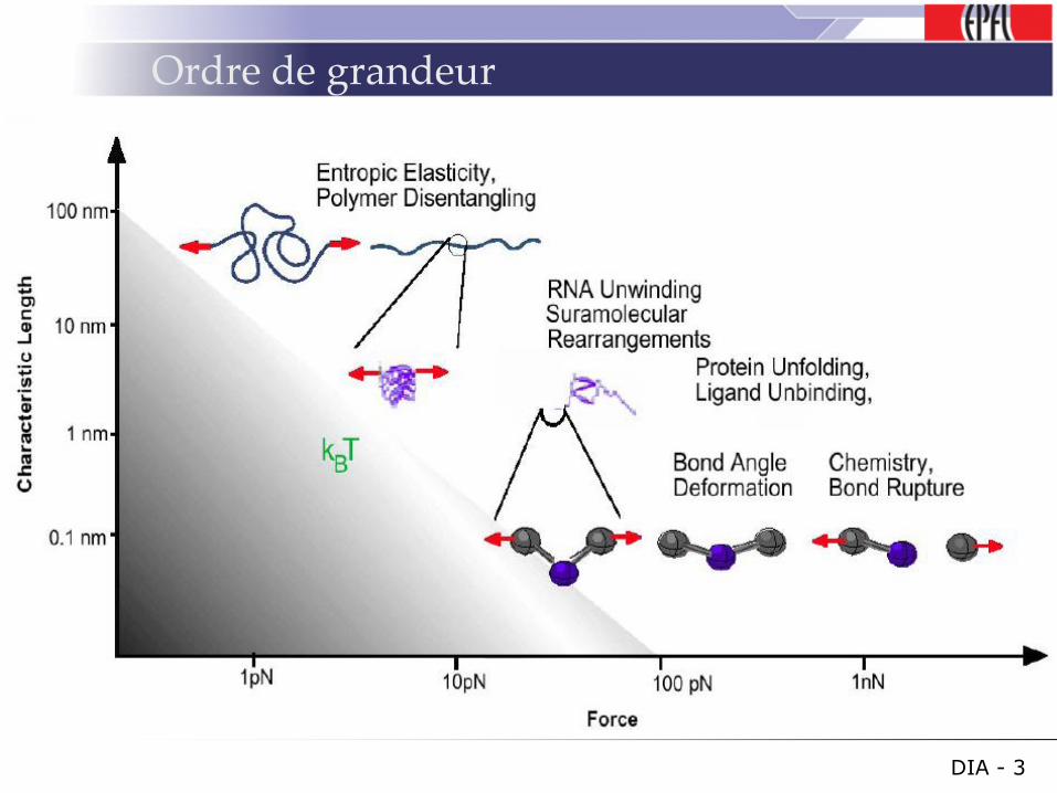
Ordre de grandeur
DIA - 3
Objectifs
Rappel biologie
• Conformation des molécules – structure tertiaire
• Sites de liaison entre molécules
• Changement de conformation dues aux conditions extérieures (chimique, mécanique, etc.)
Etudes des propriétés mécanique des molécules de leur liaison dans le but de comprendre les paramètres de ces phénomène
Comportement mécanique → fonctions biologiques
DIA - 4
Méthodes de mesure
• AFM– Fonctionnalisation de la pointe
• « Optical tweezers »– Bille diélectrique
– Détection de [pN] et déplacements [nm]
• Bille magnétique– Torsion possible
– Sensibilité : Femtonewton
• Microfibre– Moins bonne résolution
DIA - 5
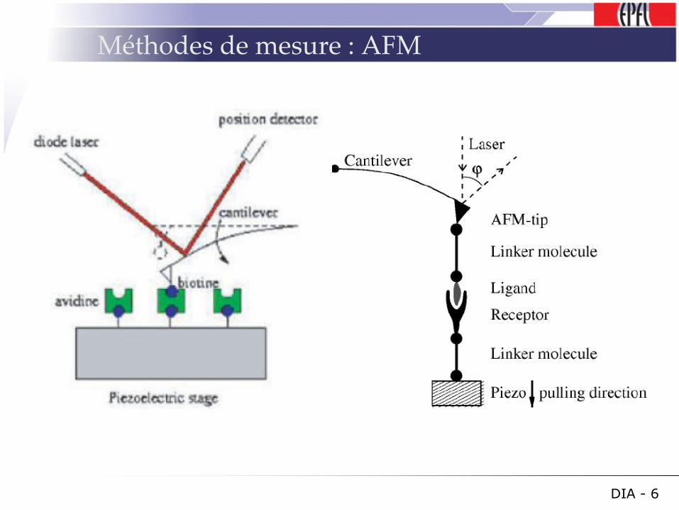
Méthodes de mesure : AFM
DIA - 6
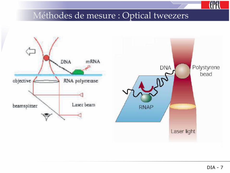
Méthodes de mesure : Optical tweezers
DIA - 7
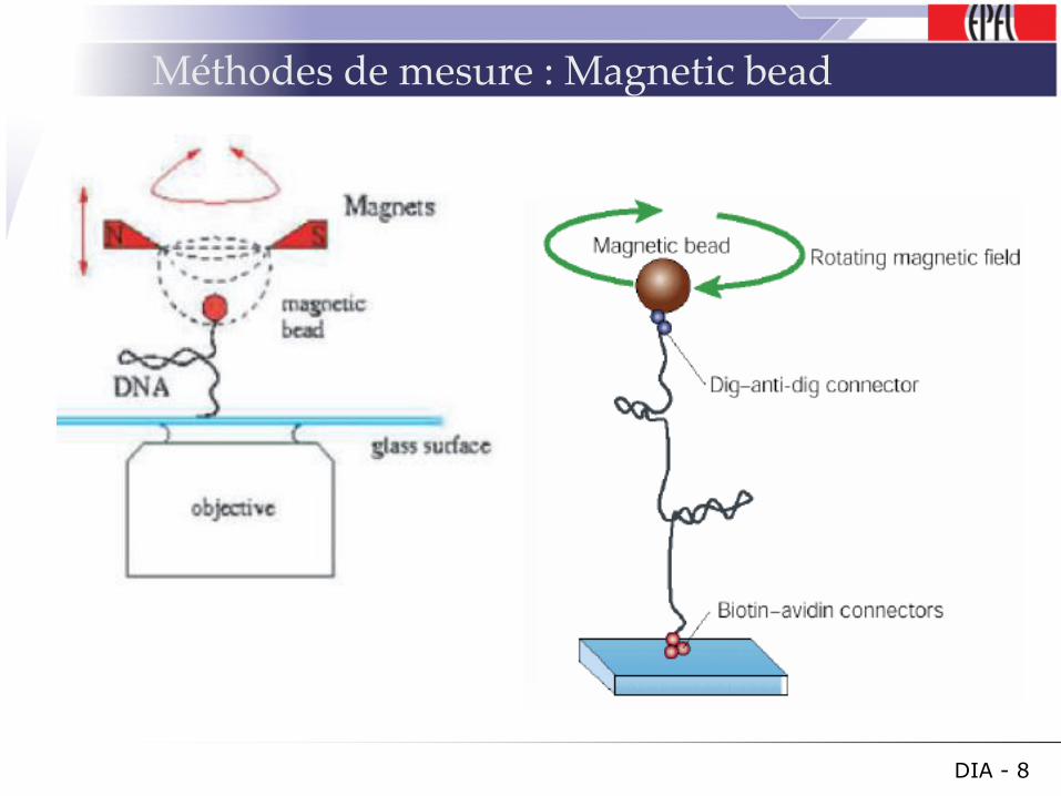
Méthodes de mesure : Magnetic bead
DIA - 8
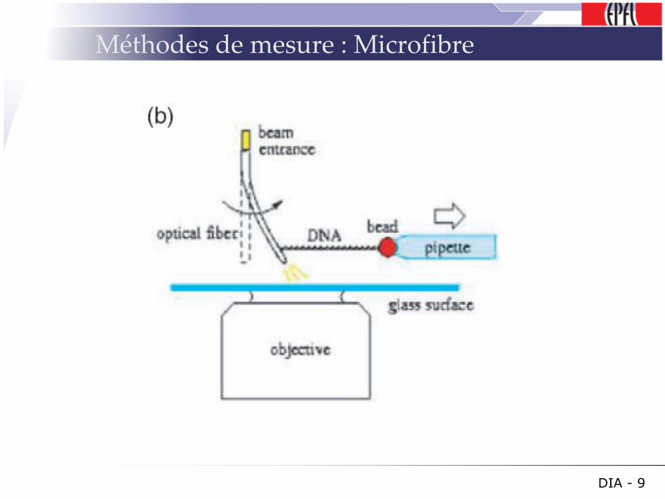
Méthodes de mesure : Microfibre
DIA - 9
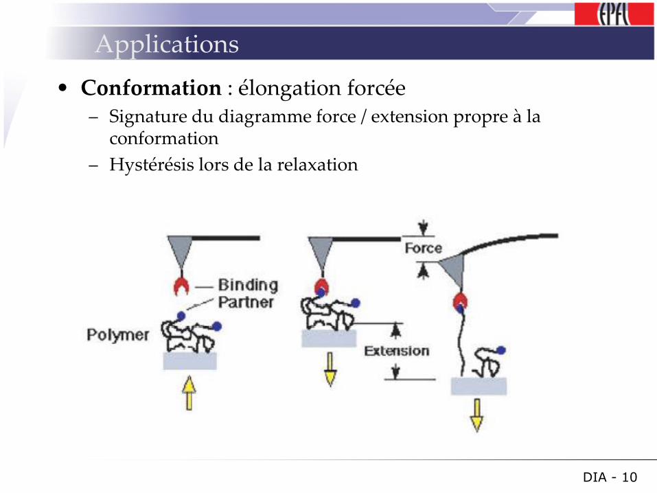
Applications
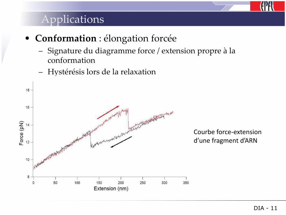
• Conformation : élongation forcée– Signature du diagramme force / extension propre à la
conformation
– Hystérésis lors de la relaxation
DIA - 10
Applications
• Conformation : élongation forcée– Signature du diagramme force / extension propre à la
conformation
– Hystérésis lors de la relaxation
DIA - 11
Courbe force-extension d’une fragment d’ARN
Applications
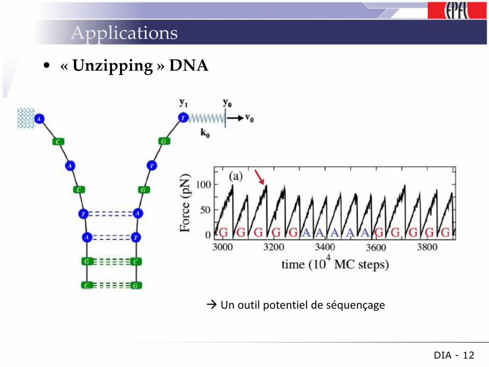
• « Unzipping » DNA
DIA - 12
Un outil potentiel de séquençage
Applications
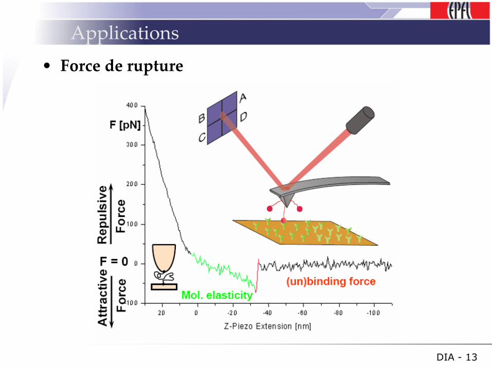
• Force de rupture
DIA - 13
Analyse
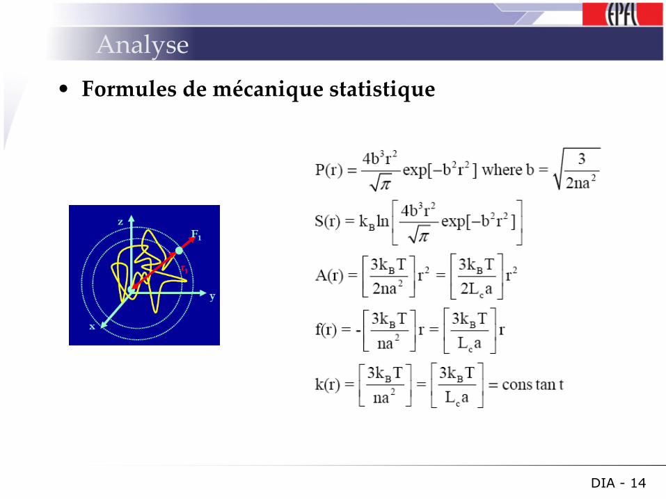
• Formules de mécanique statistique
DIA - 14
Analyse
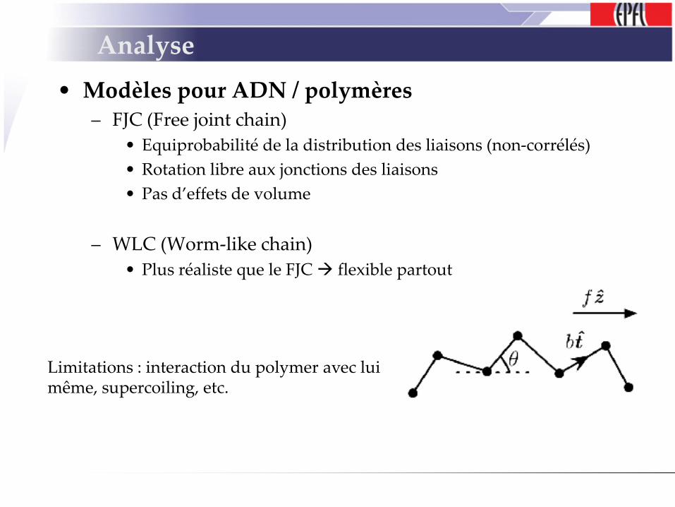
• Modèles pour ADN / polymères– FJC (Free joint chain)
• Equiprobabilité de la distribution des liaisons (non-corrélés)
• Rotation libre aux jonctions des liaisons
• Pas d’effets de volume
– WLC (Worm-like chain)
• Plus réaliste que le FJC flexible partout
Limitations : interaction du polymer avec lui même, supercoiling, etc.
Take home message
• Grand potentiel dans la recherche en biologie
• Actuellement pas encore de commercialisation
• Difficulté de modélisation du comportement des chaines polymériques
• Outils de manipulation d’objets nanométrique disponibles
DIA - 16
Références
T R Strick, M-N Dessinge, G Charvin, N H Dekker, J-F Allemand, D Bensimon and V. Croquette, Stretching of macromolecules and proteins, Rep. Prog. Phys. 66 (2003) 1–45
P. Mangeol1, D. Cote, T. Bizebard, O. Legrand, and U. Bockelmann, Probing DNA and RNA single molecules with a double optical tweezer, Eur. Phys. J. E 19, 311{317 (2006)
C. Storm and P. C. Nelson, Theory of high-force DNA stretching and overstretching, PHYSICAL REVIEW E 67, 051906 ~2003
Vogel H., Nano-Biotechnologies, force spectroscopy, course 4th, 2007
DIA - 17
Questions ?
DIA - 18

NanotechnologieSéminaire de nanomécanique
Casimir Forces :
Physics and applications
Lysandre Bonjour 2007
Content
Introduction
Physics of the Casimir forcesTheory
How to measure it
MEMS – NEMSNonlinear oscillators
Nanoscale position sensors
Quantum floatation
QED torque
Conclusion
References
Introduction
1948 : Casimir showed that by approaching two parallel plates made out of ideal metal ( unit reflectivity at all wavelength) , they should attract each other at very short distances in vacuum even if they are electrically neutral.
Generalization in the Lifshitz theory linking Casimir with Van der Waals.
• Dominant interaction mechanism between neutral objects at submicron distances !

Physics of the Casimir forces : Theory
Fluctuating virtual particles exert a "radiation pressure" on the plates which, on average is greater outside the plates than between them.
Produce a net attractive force ! (usually)
http://www.casimir.rl.ac.uk/
http://courses.washington.edu/overney/ChemE554_Course_Mat/course_material/surface_forces.pdf
Linked to VdW forces in the retarded regimes
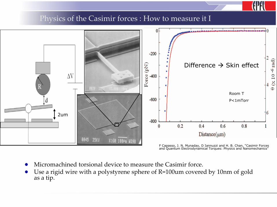
Physics of the Casimir forces : How to measure it I
Micromachined torsional device to measure the Casimir force.Use a rigid wire with a polystyrene sphere of R=100um covered by 10nm of gold as a tip.
Room T
P<1mTorr
2um
F Capasso, J. N. Munaday, D Iannuzzi and H. B. Chan, “Casimir Forces and Quantum Electrodynamical Torques: Physics and Nanomechanics”
Difference Skin effect
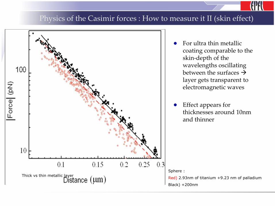
Physics of the Casimir forces : How to measure it II (skin effect)
For ultra thin metallic coating comparable to the skin-depth of the wavelengths oscillating between the surfaces layer gets transparent to electromagnetic waves
Effect appears for thicknesses around 10nm and thinner
Thick vs thin metallic layerSphere :
Red) 2.93nm of titanium +9.23 nm of palladium
Black) +200nm
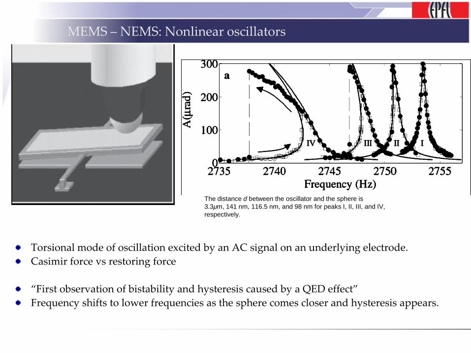
MEMS – NEMS: Nonlinear oscillators
Torsional mode of oscillation excited by an AC signal on an underlying electrode.
Casimir force vs restoring force
“First observation of bistability and hysteresis caused by a QED effect”
Frequency shifts to lower frequencies as the sphere comes closer and hysteresis appears.
The distance d between the oscillator and the sphere is
3.3μm, 141 nm, 116.5 nm, and 98 nm for peaks I, II, III, and IV,
respectively.
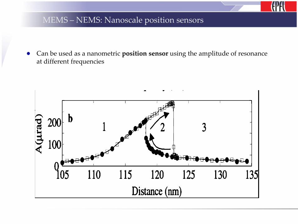
MEMS – NEMS: Nanoscale position sensors
Can be used as a nanometric position sensor using the amplitude of resonance at different frequencies

MEMS – NEMS: Casimir levitation I
Happens if the plates are immersed in a third medium with the following dielectric functions
One can calculate the Hamaker constant. If <0 repulsive force using the full Lifshitz theory
Also valid for VdW non-retarded.
ε1(iξ) < ε3(iξ) < ε2(iξ)orε2(iξ) < ε3(iξ) < ε1(iξ)
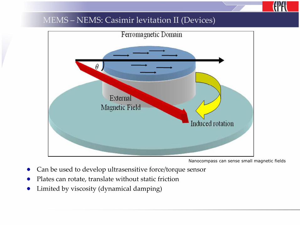
MEMS – NEMS: Casimir levitation II (Devices)
Can be used to develop ultrasensitive force/torque sensor
Plates can rotate, translate without static friction
Limited by viscosity (dynamical damping)
Nanocompass can sense small magnetic fields
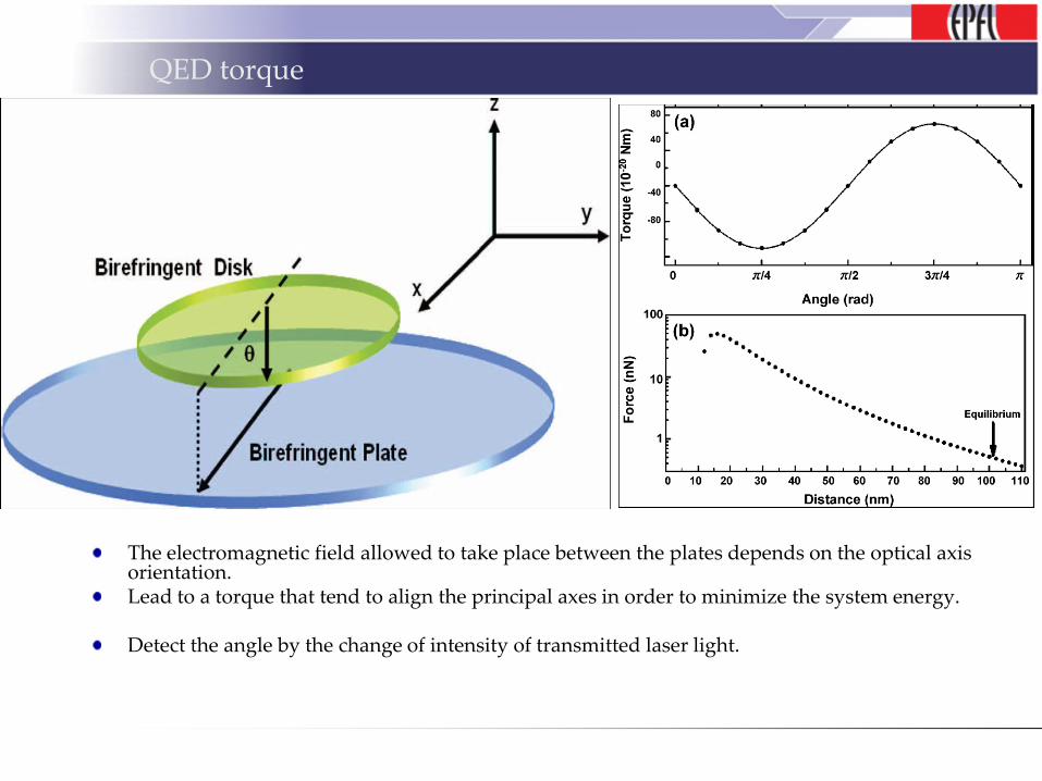
QED torque
The electromagnetic field allowed to take place between the plates depends on the optical axis orientation.Lead to a torque that tend to align the principal axes in order to minimize the system energy.
Detect the angle by the change of intensity of transmitted laser light.
Remember
Casimir effect is a QED phenomena that can be sensed at large distances ( 100-200nm).
It is closely related to VdW forces.
Il can be attractive or repulsive.
It might thus take a growing importance in the design of NEMS.
References
F Capasso, J. N. Munaday, D Iannuzzi and H. B. Chan, “Casimir Forces and Quantum Electrodynamical Torques: Physics and Nanomechanics” , IEEE journal of selected topis in quantum electronics, vol 13, n°2, march/april 2007
H. B. Chan, V. A. Aksyuk, R. N. Kleiman, D. J. Bishop, F. Capasso, “Quantum Mechanical Actuation of Microelectromechanical Systems by the Casimir Force”, Science 291, 1941 (2001)
M. Lisanti, D. Iannuzzi, and F. Capasso, “Observation of the skin-depth effect on the Casimir force between metallic surfaces”, PNAS 2005, 102, 11989-11992
http://courses.washington.edu/overney/ChemE554_Course_Mat/course_material/surface_forces.pdf


![PMU Placement to Ensure Observable Freqqyuency and Voltage Dynamics…electriconf/2012/slides/Section D2-P1/2... · References [1] Ali Abur, Optimal Plancement of Phasor Measurement](https://img.pdfslide.net/doc/110x75/5a827d217f8b9ada388de528/pmu-placement-to-ensure-observable-freqqyuency-and-voltage-dynamics-electriconf2012slidessection.jpg)