Embed Size (px)
Citation preview
1969, No. 8/9/10 241
Ultra-high-speed photography
H. Bacchi and G. Eschard
This article describes several pieces of researchdevoted to high-speed photography, some of whichhave been undertaken at the request of the FrenchAtomic Energy Commission and carried out in closecollaboration with E. Laviron and C. Delmare, of theLimeil Research Centre, and M. Marilleau, of theVaujours Research Centre.
High-speed full-image cameras can be grouped intothree categories, namely: mechanical, electro-opticaland electronic cameras.
Since 1954 mechanical cameras have provided ex-posure rates of 107 pictures per second, with the possi-bility of taking a very large number of pictures of thesame phenomenon (20 to 100, depending on the version).With these cameras there is a lower limit to the expo-sure time of about 50 ns.
Electro-optical cameras are composed from an inputlens, a shutter consisting of an electro-optic cell- usu-ally a Kerr cell situated between crossed polarizers-and a repeater lens. With these cameras, exposure isobtained by applying a voltage of 15-20 kVacross thecell. The exposure time can be reduced to a value ofabout 1 ns. The chief drawback is that the shutter trans-mits only 10-20 % of the incident light when it is open.
Electronic cameras, which first appeared on themarket in 1962, give performances which are superiorto those of the cameras already mentioned. They arealso suitable for a much wider range of applications.In this article we shall deal only with this type of camera.The heart of the camera in this case is an image-con-verter tube which acts as a shutter and is used in con-junction with an input objective and a repeater objec-tive.
The image converters which are used in these cam-eras all consist essentially of a photocathode and aluminescent screen. An image of the scene is producedon the photocathode by the objective lens; the lumi-nescent screen recei:ves the emitted photoelectrons andreproduces the image for a time which is relativelylong (0.1 to 10 milliseconds) compared to the time thetube is "open" (e.g. 1 nanosecond).
There are three main types of converter tube:
H. Bacchi, Ingenieur A. M. and E. S. E., and G.Eschard, IngenieurE. S.E., Dr. Ing., are with Laboratoires d'Electronique et de PhysiqueAppliquée, Llmell-Brévannes (Vat-de-Marne}, France.
1) Diode-type converters, consisting of a photocathodeand a screen placed in two close parallel planes; weshall describe one version in greater detail below.
2) Triode-type converters, in which' operation of thetube is controlled by an electrode in the form of agrid or ring [1].
3) Converters with deflection plates, in which theshutter function is achieved by shifting the electronbeam past a diaphragm ofvery small dimensions [2].
Other types of converter exist which offer possibilitiesfor information storage [3] or charge storage, but theyare not yet widely used.
In addition to its function as a shutter an image-converter tube gives a gain in photons and can ifnecessary be coupled to an image intensifier. Thismakes it possible for an electronic camera to photographwith very short exposure times phenomena which arenot bright enough to be photographed by an electro-optical camera.
As its name indicates, the image converter can alsoeffect conversion of the light frequencies, and it can besensitive to radiation of different wavelengths, depend:'ing on the photocathode used. For example, when thetype S 1 photocathode which is sensitive up to 1.1 !J.mis employed, frequency conversion takes place sincethe screenwhich reproducestheimage delivers radiationat a wavelength situated in the visible spectrum, cen-tred on 0.55 !J.m. This conversion makes it possible touse films of very high sensitivity which are practicallynon-existent for the higher wavelengths.
The lower limit of exposure time provided by thesetubes is governed either by the transit times of thephotoelectrons between the photocathode and thescreen or by propagation phenomena at the surface ofthe photocathode. These phenomena, which are pecu-liar to the tube, lead in practice to a lower exposure-time limit of the order of 100 picoseconds.
A converter-tube shutter is opened by applying ahigh-voltage pulse, usually between 15 and 20 kV, tothe electrodes. The width of this pulse approximately
[1] See for example J. A. Jenkins and R. A. Chippendale,High-speed photography by means of the image converter,Philips tech. Rev. 14, 213-225, 1952/53.
[2] A. E. Huston, Proc. 3rd Symp. on Photoelectronic imagedevices, London 1965, pp. 963-966.
[3] R. W. Smith, in: High-Speed Photography, Proc. 8th Int.Congress, Stockholm 1968, pp. 18-20.
242 PHILIPS TECHNICAL REVIEW VOLUME 30
determines the exposure time. If it is desired to obtainexposure times approaching the limiting value allowedby the tube, the control circuits have to deliver pulseswhose rise and fall times are of the order of one hun-dred picoseconds.The essential characteristics of the tubes and the
control circuits are a direct consequence of theserequirements. In fact, a voltage variation occurring insuch a short time can only be effectively applied to atube if it is transmitted by a transmission line whosehighest operating frequency is of the order of 3 GHz.The tube, of course, has to form an integral part of thistransmission line, a circumstance which determines thegeometry of the structure on which the sensitive layershave to be formed.Allowing for the relatively short distance between the
photocathode and the screen (cf. formula 1) and forthe need to have a useful surface area of severalsquare centimetres, we are obliged to use a transmis-sion line with a characteristic impedance of approxi-mately 25 n, and this means that the current will reacha value ofabout 600A when a pulse of 15kV is applied.Therefore, the trigger circuits have to include a high-speed spark gap, and our best results were obtainedwith a gap of coaxial structure [41[51.
We shall see later that the rise time of the leadingedge of the wave produced by a circuit comprising aspark gap is proportional to the distance between theelectrodes of the gap [61. A lower limit is imposed onthis distance by two factors: a) the usefullife, which willbe shortened when the gap is reduced, b) the pressureof the gas in the spark-gap cavity. In fact, the operatingvoltage of the spark gap is determined by the voltagerequired for the shutter tube, and, iffor a given voltagewedecide to decrease the distance between the electrodes,we are obliged to increase the pressure (Paschen's law).Technological problems limit the pressure to twenty orthirty bars, and consequently the distance betweenthe electrodes is made a few tenths of a millimetre.The final parameters which determine the minimum
length of the rise time are therefore the distance be-tween the electrodes of the spark gap and the quality ofthe various matching elements along the transmissionline linking the spark gap to the shutter tube.Additional requirements concerning the drive circuit
come into play if it is desiréd to obtain a perfectlyuniform transmission factor during the exposure andfor an accurately defined time. If before and after theactual exposure time the camera has to present themaximum opacity permitted by the converter tube, thewaveform ofthe appliéd pulse must remain fairly accur-ately rectangular despite the extremely short duration.The necessary circuits can now be realized thanks to
the progress made at LEP in the fieldof spark gaps with
ultra-high-speed triggering, inserted in coaxial lines.The performance of these spark gaps will be improvedstill further as a result of research at present in progress.We now propose to give a brief description ofthe con-
verter tubes developed at LEP and of several types ofcamera in which these tubes are used. A description ofthe tubes has been given by Eschard and Polaert [7] andvarious equipments have already been described inreferences [41 and [51. These equipments were also thesubject of a paper read before the Eighth InternationalCongress on High-Speed Photography in 196~ [81.
Several examples of spark gaps with two or threeelectrodes, developed at the Laboratoire Central del'Armement and LEP have also been described inthese articles.
Image-converter tubes
For a number of years now we have been developinga whole family of biplanar diode shutters [91. Theseshutters are very similar in their underlying principleand are based on the technique of activation of photo-cathodes by the transfer method [lOl. On page 235 inthis issue a laboratory equipment is shown with whichit is possible to make tubes whose useful diameter maybe as much as 120 mm. This is important sinceone of the interesting points about this type of shutteris that it enables the definition of the image to be in-creased by using increasing diameters.
The main characteristics of these shutters werediscussed in a recent paper [111. We shall first brieflyrecapitulate the main features to bring out the pointswhich have been the subject of new developments,particularly the possibility of using cathodes which aresensitive up to the near infra-red and constructionssuitable for very short exposure times.
Quality of the image
If we place the screen a distance d from the photo-cathode, the defocusing due to initial velocities resultsin the following formula for the resolution R (linepairs per mm):
0.61/ VR=d ~(~_ 1 )'
e A Ao
. . (1)
in which h is Planck's constant, c the velocity of light,e the electron charge, A the wavelength of the incidentlight, Ao the wavelength of the transmission thresholdof the photocathode, and Vthe voltage applied at theterminals of the tube (all in SI units).
A resolution of the order of 15 line pairs per milli-metre can be obtained when the distance d is sufficientlysmall. When the useful diameter of the image is as
1969, No. 8/9/10 ULTRA-HIGH-SPEED PHOTOGRAPHY 243
much as 60 mm, the resolution of the image can beas great as 1000 line pairs per diameter. The absenceof distortion is very important, especially when it isrequired to measure physical characteristics, particlevelocities or deformation of materials, or to examinespectra.
Opacity factor
in this range of shutters attenuation of the. incidentlight is due chiefly to a metallic backing on the lumi-nescent screen. The opacity factor depends on thethickness of the metallayer; it is limited by the numberand dimensions of micro-fissures in the layer. If theimage of a uniformly illuminated surface is examinedwhen the tube is not supplied with power, a series ofdots corresponding to faults in the backing will beobserved. We have developed a method which allowsan opacity factor of over 105 to be attained with a P 11screen.
Shutter speed
The main factors limiting the shutter speed are thetransit time of the photoelectrons, the conductivity ofthe electrodes, space-charge effects and the mannerin which the tube is integrated into the transmissionline.If allowance is made for the shape of the voltage
pulse, it can be shown that a transit time of less than80 picoseconds allows the tube to be used with a mini-mum exposure time of 100 picoseconds. This is not,therefore, the limiting factor in present tubes but weshall see that it will affect future developments, and thesame can be said of the space charge.The way in which the problem ofthe conductivity of
the electrodes is tackled can be explained as follows.Both the photocathode and the luminescent screenshould have sufficient conductivity for the voltage pulseto travel to the centre ofthe tube without undue defor-
[4] E. Laviron, C. Delmare and H. Bacchi, Caméras électroni-ques de 1 ns de durée d'ouverture, Onde électr. 48, 421-425,1968 (No. 494).
[5] H. Bacchi and M. Blanchet, Générateurs d'impulsions hautetension de 1 nanoseconde à mi-hauteur, Onde électr. 48,430-437, 1968 (No. 494).
[6] G. A. Mesjac ·and V. V. Kremnev, Raideur maximale dufront de montée dans un circuit RLC avec éclateur à étincelles,Bull. Acad. Sci. U.R.S.S., Sci. techno En. Transp., 1963, No.1, pp. 53-57 (in Russian). .
[7] G. Eschard and R. Polaert, Tube obturateur pour photographieultra-rapide, Onde électr. 48, 426-429, 1968 (No. 494).
[8] H. Bacchi and. J. Marillleau, in: High-Speed Photography,Proc. 8th Int. Congress, Stockholm 1968, pp: 57-60; E. Lavi-ron and H. Bacchi, ibid. pp. 61-63.
[9] G. Eschard and R. Polaert, in: High-Speed Photography,Proc. 8th Int. Congress, Stockholm 1968, pp. 54-56.
[10] P. Dolizy and R. Legoux, Proc. 4th Symp. on Photoelectron-ie image devices, London 1968; see also R. Legoux, page 234of this issue.
[11] G. Eschard and R. Polaert, Proc. 4th Syrup. on Photoelec-tronie image devices, London 1968.
mation. The screens commonly used in this type of tubemeet this requirement. The normal photocathodes how-ever are very poor conductors. We have measured sur-face-resistivityvalues of 108ohms per square. Aconduct-ing sub-layer must therefore be applied, but this will ab-sorb part of the incident light. For an exposure timeof 1 ns the surface resistance of the sub-layer shouldamount to some dozens of ohms per square. This isobtained at a loss of the order of 50% in gain. For thedevelopment of shutter tubes of even higher speed theuse ofhighly conductive and therefore highly absorbingsub-layers will be unavoidable. In this case the lightlosses may be reduced by applying the conductinglayer in an array of very narrow metallic bands, andthe types of layer now in use will serve the purpose.To obtain operating times of less than a nanosecond,
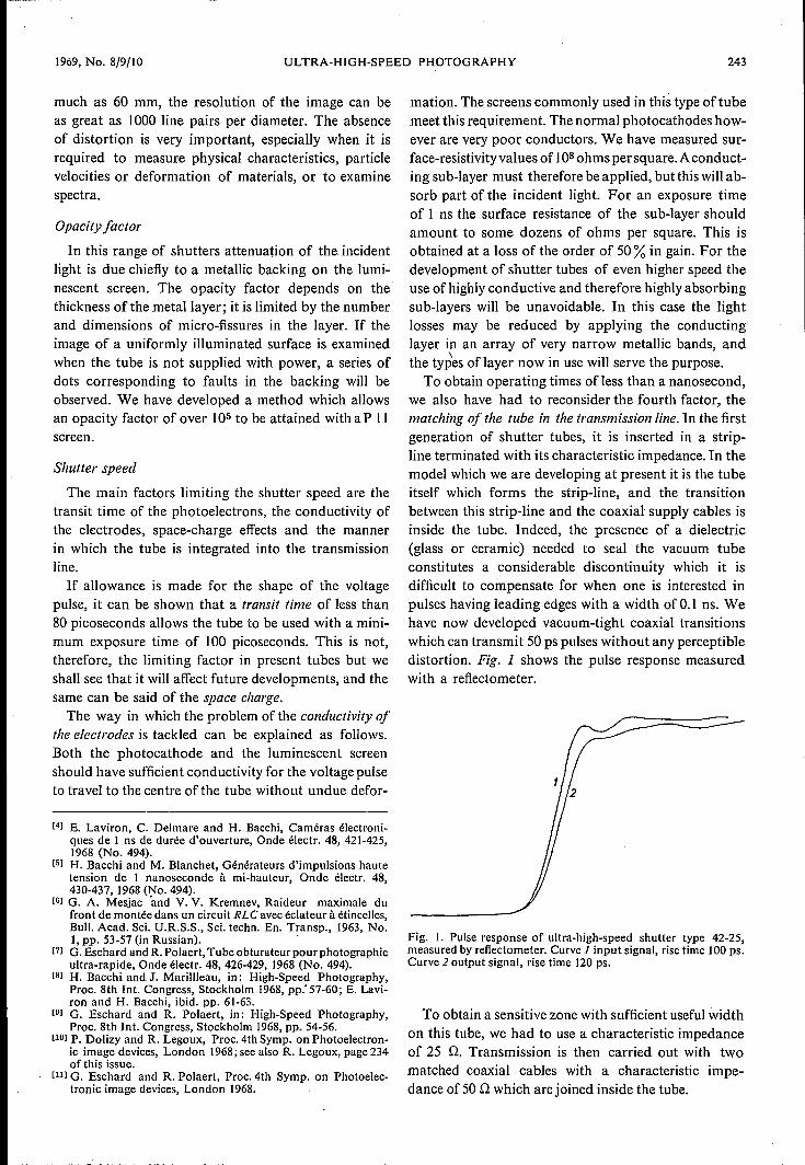
we also have had to reconsider the fourth factor, thematching of the tube in the transmission line. In the firstgeneration of shutter tubes, it is inserted in a strip-line terminated with its characteristic impedance. In themodel which we are developing at present it is the tubeitself which forms the strip-line, and the transitionbetween this strip-line and the coaxial supply cables isinside the tube. Indeed, the presence of a dielectric(glass or ceramic) needed to seal the vacuum tubeconstitutes a considerable discontinuity which it isdifficult to compensate for when one is interested inpulses having leading edges with a width ofO.l ns. Wehave now developed vacuum-tight coaxial transitionswhich can transmit 50 ps pulses without any perceptibledistortion. Fig. 1 shows the pulse response measuredwith a refiectometer.
Fig. 1. Pulse response of ultra-high-speed shutter type 42-25,measured by reflectometer. Curve 1input signal, rise time lOOps.Curve 2 output signal, rise time 120 ps.
To obtain a sensitive zone with sufficient useful widthon this tube, we had to use a characteristic impedanceof 25 Q. Transmission is then carried out with twomatched coaxial cables with a characteristic impe-dance of 50Q which are joined inside the tube.
244 PHILlPS TECHNICAL REVIEW VOLUME 30
Photocathode
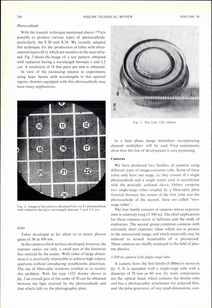
With the transfer technique mentioned above [10] it ispossible to produce various types of photocathode,particularly the S 20 and S 24. We recently adaptedthis technique for the production of tubes with silver-caesium layers (S 1), which are sensitive in the near infra-red. Fig.2 shows the image of a test pattern obtainedwith radiation having a wavelength between 1 and 1.2[Lm. A resolution of 18 line pairs per mm is obtained.
In view of the increasing interest in experimentsusing laser beams with wavelengths in this spectralregion, shutters equipped with this photocathode mayhave many applications.
Fig. 2. Image of test pattern obtained from an S J photocathodewith radiation having a wavelength between J and J.2 fLm.
Gain
Tubes developed so far allow us to attain photongains of 30 at 430 nm.
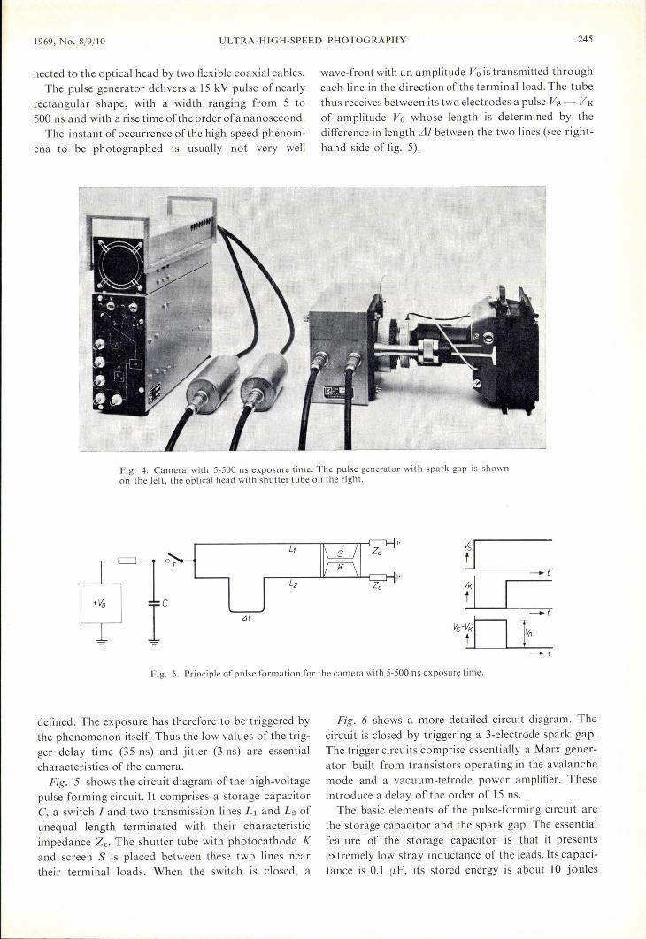
ln the cameras which we have developed, however, therepeater optics use only a small part of the luminousflux emitted by the screen. With tubes of large dimen-sions it is practically impossible to achieve high relativeapertures without introducing troublesome distortion.The use of fibre-optic windows enabled us to resolvethis problem. With the type J 325 shutter shown infig. 3 an overall gain of the order of 30 can be obtainedbetween the light received by the photocathode andthat which falls on the photographic plate.
Fig. 3. The type 1325 shutter.
In a later phase image intensifiers incorporatingchannel multipliers will be used. First experimentsshow that this line of development is very promising.
Cameras
We have produced two families of cameras usingdifferent types of image-converter tube. Some of thesetubes only have one stage, i.e. they consist of a singlephotocathode and a single screen used in accordancewith the principle outlined above. Others comprisetwo single-stage tubes coupled by a fibre-optic plateinserted between the screen of the first tube and thephotocathode of the second; these are called "two-stage tubes".
The first family consists of cameras whose exposuretime is relatively long (5-500 ns). The chief applicationsfor these cameras occur in ballistics and the study ofexplosives. The second group comprises cameras withextremely short exposure times which are at presentin the nanosecond range, and which eventually may bereduced to several hundredths of a picosecond.These cameras are chiefly em ployed in the field of plas-ma physics.
5-500 ns camera with single-stage tube
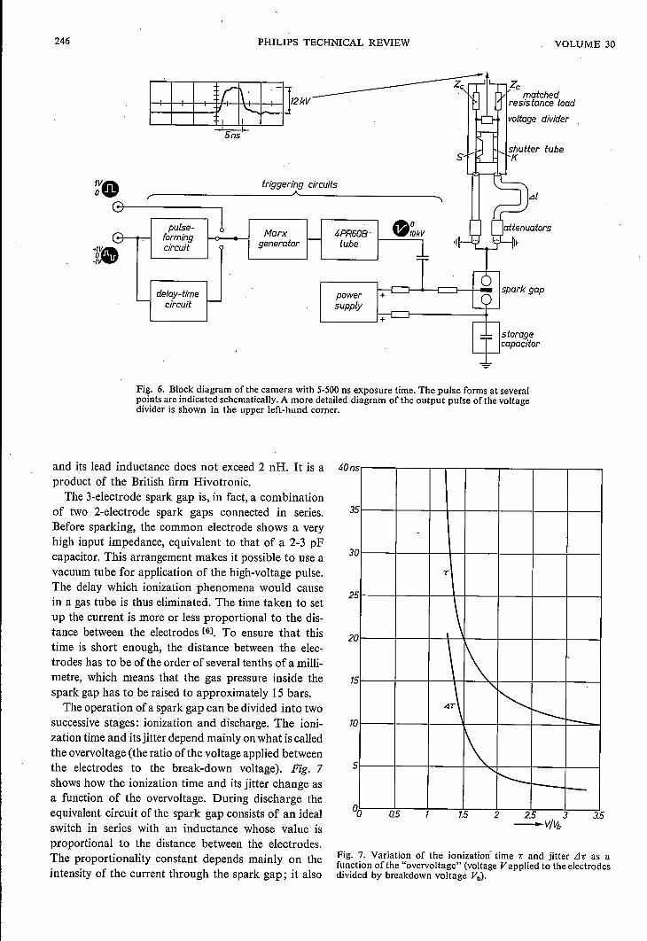
A camera from the first family (5-500ns) is shown infig. 4. It is equipped with a single-stage tube with adiameter of 38 mm or 60 mm. Its main componentsare the optical head, which contains the shutter tubeand has a photographic attachment for polaroid film,and the pulse generator, of very small dimensions, con-
1969, No. 8/9/10 ULTRA-HIGH-SPEED PHOTOGRAPHY 245
nected to the optical head by two flexible coaxial cables.The pulse generator delivers a 15 kV pulse ofnearly
rectangular shape, with a width ranging from 5 to500 ns and with a rise time ofthe order of a nanosecond.
The instant of occurrence of the high-speed phenom-ena to be photographed is usually not very well
wave-front with an amplitude Va is transmitted througheach line in the direction of the terminal load. The tubethus receives between its two electrodes a pulse Vs- VKof amplitude Va whose length is determined by thedifference in length Lil between the two lines (see right-hand side of fig. 5).
Fig. 4. Camera with 5-500 ns exposure time. The pulse generator with spark gap is shownon the left, the optical head with shutter tube on the right.
I"
~1"
tKI-t
+Vo r .èJ{
VS-tKI I-t
-}--t
Fig. 5, Principle of pulse formation for the camera with 5-500 ns exposure time.
defined. The exposure has therefore to be triggered bythe phenomenon itself. Thus the low values of the trig-ger delay time (35 ns) and jitter (3 ns) are essentialcharacteristics of the camera.
Fig. 5 shows the circuit diagram of the high-voltagepulse-forming circuit. It comprises a storage capacitorC, a switch I and two transmission lines L: and L2 ofunequal length terminated with their characteristicimpedance Ze. The shutter tube with photocathode Kand screen S is placed between these two lines neartheir terminal loads. When the switch is closed, a
Fig. 6 shows a more detailed circuit diagram. Thecircuit is closed by triggering a 3-elect[ode spark gap.The trigger circuits comprise essentially a Marx gener-ator built from transistors operating in the avalanchemode and a vacuum-tetrode power amplifier. Theseintroduce a delay of the order of 15 ns.The basic elements of the pulse-forming circuit are
the storage capacitor and the spark gap. The essentialfeature of the storage capacitor is that it presentsextremely low stray inductance of the leads. Its capaci-tance is 0.1 [LF, its stored energy is about 10 joules
246 PHILIPS TECHNICAL REVIEW VOLUME 30
:ia.Gf--------,!pulse-
formingcircuit
triggering circuits
voltage divider
shutter tubeK
Marxgenerator
delay-timecircuit
LJI
4PR60B'tube
powersupply
Fig. 6. Block diagram of the camera with 5-500 ns exposure time. The pulse forms at severalpoints are indicated schematically. A more detailed diagram of the output pulse ofthe voltagedivider is shown in the upper left-hand corner.
and its lead inductance does not exceed 2 nR. It is aproduct of the British firm Hivotronic,
The 3-electrode spark gap is, in fact, a combinationof two 2-electrode spark gaps connected in series.Before sparking, the common electrode shows a veryhigh input impedance, equivalent to that of a 2-3 pFcapacitor. This arrangement makes it possible to use avacuum tube for application of the high-voltage pulse.The delay which ionization phenomena would causein a gas tube is thus eliminated. The time taken to setup the current is more or less proportional to the dis-tance between the electrodes [6l. To ensure that thistime is short enough, the distance between the elec-trodes has to be of the order of several tenths of a milli-metre, which means that the gas pressure inside thespark gap has to be raised to approximately 15 bars.The operation of a spark gap can be divided into two
successive stages: ionization and discharge. The ioni-zation time and its jitter depend mainly onwhat is calledthe overvoltage (the ratio ofthe voltage applied betweenthe electrodes to the break-down voltage). Fig. 7shows how the ionization time and its jitter change asa function of the overvoltage. During discharge theequivalent circuit of the spark gap consists of an idealswitch in series with an inductance whose value isproportional to the distance between the electrodes.The proportionality constant depends mainly on theintensity of the current through the spark gap; it also
40ns
10
-
T
\
.\1\
A "<,---- :---1\'!'---t-
35
30
25
20
15
5
Q5 1.5 2 2.5 3-V/l1>
3.5
Fig. 7. Variation of the ionization time Tand jitter Lh as afunction ofthe "overvoltage" (voltage Vapplied to the electrodesdivided by breakdown voltage Vb)'
1969, No. 8/9/10 ULTRA-HIGH-SPEED PHOTOGRAPHY 247
depends, but to a lesser degree, on the nature of the gasand the shape and nature of the electrodes, and it ispractically independent of the pressure. For a currentof approximately 500 A, the proportionality constant isof the order of 45 nB/mm.
We have studied the effect of a certain number ofparameters, particularly the distance between the elec-trodes, on the service life of high-speed spark gaps. It
page 214). It will have a sealed spark gap, whichmakes it easier to operate.
Test facilities for exposure times between 5 and 500 ns
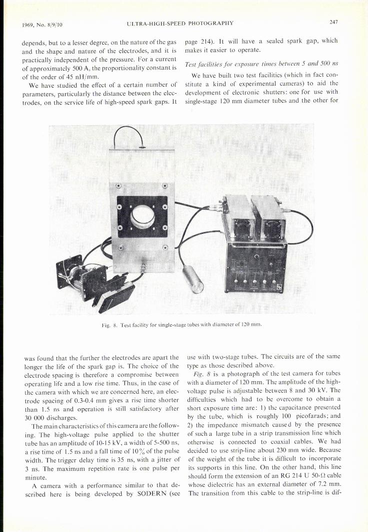
We have built two test facilities (which in fact con-stitute a kind of experimental cameras) to aid thedevelopment of electronic shutters: one for use withsingle-stage 120 mm diameter tubes and the other for
Fig. 8. Test facility for single-stage tubes with diameter of 120 mm.
was found that the further the electrodes are apart thelonger the life of the spark gap is. The choice of theelectrode spacing is therefore a compromise betweenoperating life and a low rise time. Thus, in the case ofthe camera with which we are concerned here, an elec-trode spacing of 0.3-0.4 mm gives a rise time shorterthan 1.5 ns and operation is still satisfactory after30 000 discharges.
The main characteristics of this camera are the follow-ing. The high-voltage pulse applied to the shuttertube has an amplitude of 10-15 kV, a width of 5-500 ns,a rise time of 1.5 ns and a fall time of 10% of the pulsewidth. The trigger delay time is 35 ns, with a jitter of3 ns. The maximum repetition rate is one pulse perminute.
A camera with a performance similar to that de-scribed here is being developed by SODERN (see
use with two-stage tubes. The circuits are of the sametype as those described above.
Fig. 8 is a photograph of the test camera for tu beswith a diameter of 120 mm. The amplitude of the high-voltage pulse is adjustable between 8 and 30 kV. Thedifficulties which had to be overcome to obtain ashort exposure time are: 1) the capacitance presentedby the tube, which is roughly 100 picofarads ; and2) the impedance mismatch cause d by the presenceof such a large tube in a strip transmission line whichotherwise is connected to coaxial cables. We haddecided to use strip-line about 230 mm wide. Becauseof the weight of the tube it is difficult to incorporateits supports in this line. On the other hand, this lineshould form the extension of an RG 214 U 50-1.1cablewhose dielectric has an external diameter of 7.2 mm.The transition from this cable to the strip-line is dif-
248 PHJLTPS TECHNICAL REVIEW VOLUME 30
ficult to achieve with good matching of the characteristicimpedance and a sufficient dielectric strength towithstand 30 kV. Despite these difficulties the exposuretime is still less than 10 nanoseconds. The performance
111 other respects is identical to that of the cameradescribed above.
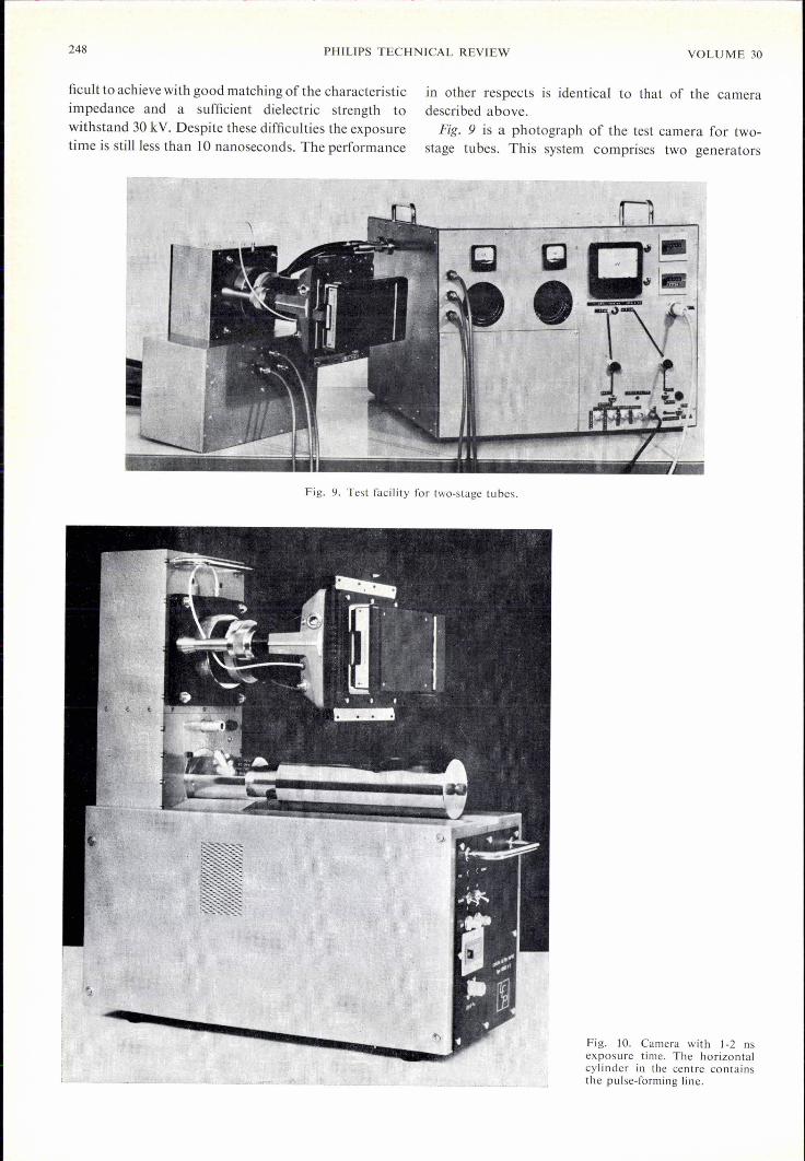
Fig. 9 is a photograph of the test camera for two-stage tubes. This system comprises two generators
Fig. 9. Test facility for two-stage tubes.
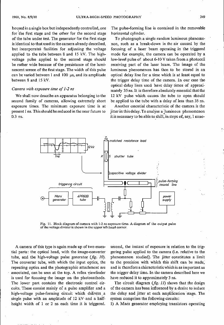
Fig. 10. Camera with 1-2 nsexposure time. The horizontalcylinder in the centre containsthe pulse-forming line.
1969, No. 8/9/10 ULTRA-HIGH-SPEED PHOTOGRAPHY 249
housed in a single box but independently controlled, onefor 'the first stage and the other for the second stageof the tube under test. The generator for the first stageis identical to that used in the camera already described,but incorporates facilities for adjusting the voltageapplied to the tube between 8 and 15 kV. The high-voltage pulse applied to the second stage shouldbe rather wide because of the persistance of the lumi-nescent screen of the first stage. The width of this pulsecan be varied between 1 and 100 (J.s,and its amplitudebetween 8 and 15 kV.
Camera with exposure time of 1-2 ns
We shall now describe an apparatus belonging to thesecond family of cameras, allowing extremely shortexposure times. The minimum exposure time is atpresent 1ns. This should be reduced in the near future to0.3 ns.
triggenng circuit
Marxgenerator
4PR60Btube
The pulse-forming line is contained in the removablehorizontal cylinder.
To photograph a single random luminous phenome-non, such as a break-down in the air caused by thefocusing of a laser beam operating in the triggeredmode for example, the camera can be operated by alow-level pulse of about 6-10 V taken from a photocellreceiving part of the laser beam. The image of theluminous phenomenon has then to be stored in anoptical delay line for a time which is at least equal tothe trigger delay time of the camera. In our case theoptical delay lines used have delay times of approxi-mately 35 ns. It is therefore absolutely essential that the12 kV pulse which causes the tube to open shouldbe applied to the tube with a delay of less than 35 ns.
Another essential characteristic of the camera is thejitter in this delay. To analyse a -Iuminous phenomenon.it is necessary to be able to shift, in steps of, say, 1nano-
Zematched resistance load
S shutter tube
capacitive voltage divider
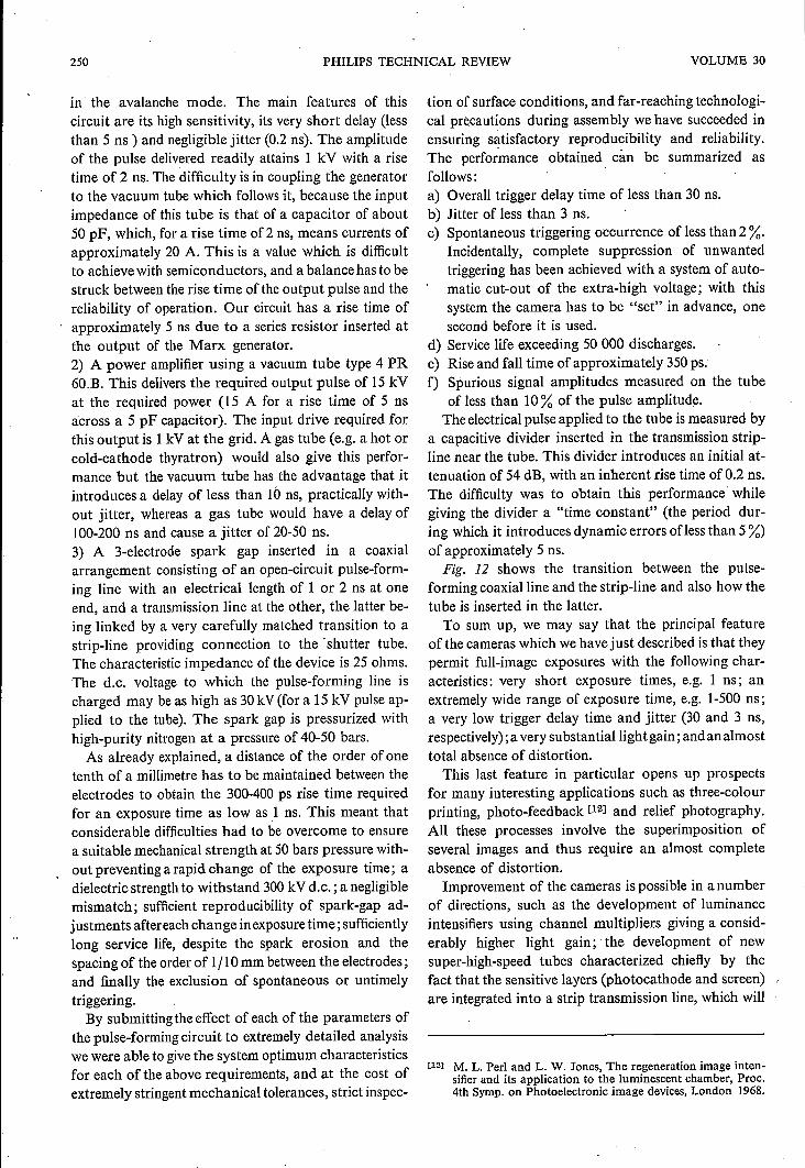
Fig. 11. Block diagram of camera with 1-2 ns exposure time. A diagram of the output pulseofthe voltage divider is shown in the upper left-hand corner.
A camera of this type is again made up of two essen-tial parts: the optical head, with the image-convertertube, and the high-voltage pulse generator (fig. la).The converter tube, with which the input optics, therepeating optics and the photographic attachment are
, associated, can be seen at the top. A reflex viewfinderis used for focusing the image on the photocathode.The lower part contains the electronic control cir-cuits. These consist mainly of a pulse amplifier and ahigh-voltage pulse-forming circuit which delivers asingle pulse with an amplitude of 12 kYand a half-height width of 1 or 2 ns each time it is triggered.
second, the instant of exposure in relation to the trig-gering pulse applied to the camera (i.e. relative to thephenomenon studied). The jitter constitutes a limitto the precision with which this shift can be made;and is therefore a chàracteristic which is as important asthe trigger delay time. In the camera described here wehave reduced it to approximately 3 ns.
The circuit diagram (fig.' 11) shows that the designof the camera has been influenced by a desire to reducethe delay and jitter at each amplification stage. Thesystem comprises the following circuits:1) A Marx generator employing transistors operating
250 PHILIPS TECHNICAL REVIEW VOLUME 30
in the avalanche mode. The main features of thiscircuit are its high sensitivity, its very short delay (lessthan 5 ns ) and negligible jitter (0.2 ns). The amplitudeof the pulse delivered readily attains 1 kV with a risetime of 2 ns. The difficulty is in coupling the generatorto the vacuum tube which follows it, because the inputimpedance of this tube is that of a capacitor of about50 pF, which, for a rise time of2 ns, means currents ofapproximately 20 A. This is a value which is difficultto achieve with semiconductors, and a balance has to bestruck between the rise time ofthe output pulse and thereliability of operation. Our circuit has a rise time ofapproximately 5 ns due to a series resistor inserted atthe output of the Marx generator.2) A power amplifier using a vacuum tube type 4 PR60 B. This delivers the required output pulse of 15 kVat the required power (15 A for a rise time of 5 nsacross a 5 pF capacitor). The input drive required forthis output is 1 kV at the grid. A gas tube (e.g. a hot orcold-cathode thyratron) would also give this perfor-mance but the vacuum tube has the advantage that itintroduces a delay of less than rö ns, practically with-out jitter, whereas a gas tube would have a delay of100-200 ns and cause a jitter of 20-50 ns.3) A 3-electrode spark gap inserted in a coaxialarrangement consisting of an open-circuit pulse-form-ing line with an electrical length of 1 or 2 ns at oneend, and a transmission line at the other, the latter be-ing linked by a very carefully matched transition to astrip-line providing connection to the 'shutter tube.The characteristic impedance of the device is 25 ohms.The d.c. voltage to which the pulse-forming line ischarged may be as high as 30 kV (for a 15 kV pulse ap-plied to the tube). The spark gap is pressurized withhigh-purity nitrogen at a pressure of 40-50 bars.
As already explained, a distance of the order of onetenth of a millimetre has to be maintained between theelectrodes to obtain the 300-400 ps rise time requiredfor an exposure time as low as 1 ns. This meant thatconsiderable difficulties had to be overcome to ensurea suitable mechanical strength at 50 bars pressure with-out preventing a rapid change of the exposure time; adielectric strength to withstand 300 kV d.c.; a negligiblemismatch; sufficient reproducibility of spark-gap ad-justments aftereach change in exposure time; sufficientlylong service life, despite the spark erosion and thespacing of the order of 1/ I 0 mm between the electrodes;and finally the exclusion of spontaneous or untimelytriggering.
By submitting the effect of each of the parameters ofthe pulse-forming circuit to extremely detailed analysiswe were able to give the system optimum characteristicsfor each of the above requirements, and at the cost ofextremely stringent mechanical tolerances, strict inspec-
tion of surface conditions, and far-reaching technologi-cal precautions during assembly we have succeeded inensuring satisfactory reproducibility and reliability.The performance obtained can be summarized asfollows:a) Overall trigger delay time of less than 30 ns.b) Jitter of less than 3 ns.c) Spontaneous triggering occurrence of less than 2%.
Incidentally, complete suppression of unwantedtriggering has been achieved with a system of auto-matic cut-out of the extra-high voltage; with thissystem the camera has to be "set" in advance, onesecond before it is used.
d) Service life exceeding 50 000 discharges.e) Rise and fall time of approximately 350 ps.f) Spurious signal amplitudes measured on the tube
of less than 10% of the pulse amplitude.The electrical pulse applied to the tube is measured by
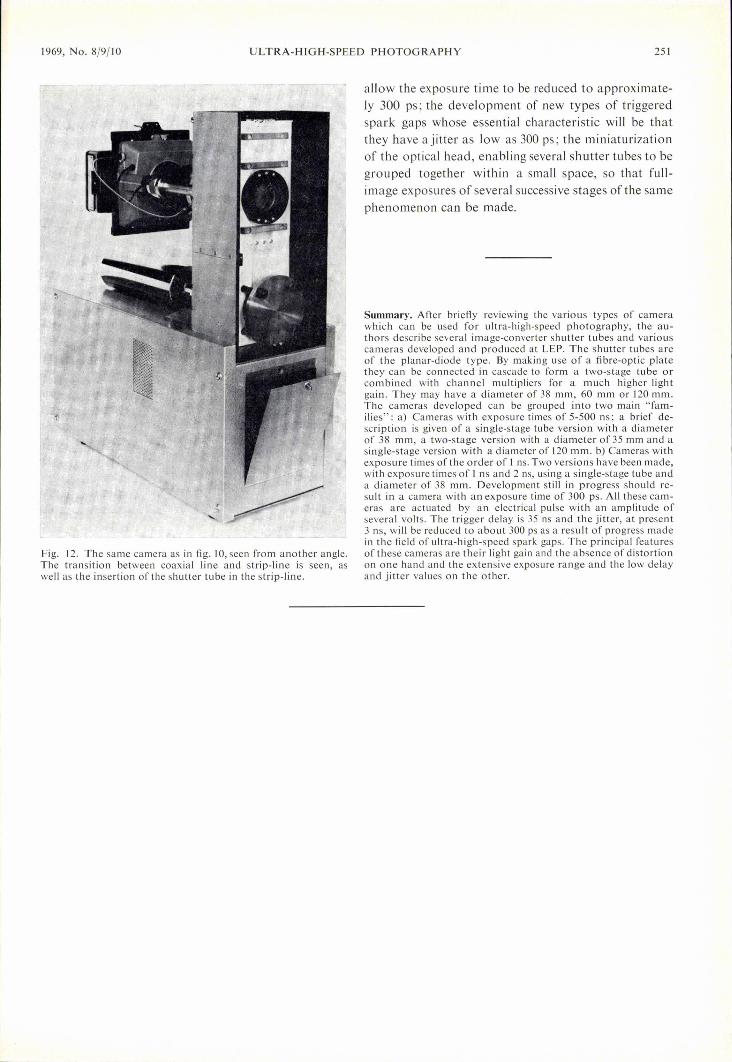
a capacitive divider inserted in the transmission strip-line near the tube. This divider introduces an initial at-tenuation of 54 dB, with an inherent rise time of 0.2 ns.The difficulty was to obtain this performance whilegiving the divider a "time constant" (the period dur-ing which it introduces dynamic errors ofless than 5%)of approximately 5 ns.Fig. 12 shows the transition between the pulse-
forming coaxialline and the strip-line and also how thetube is inserted in the latter.
To sum up, we may say that the principal featureof the cameras which we have just described is that theypermit full-image exposures with the following char-acteristics: very short exposure times, e.g. Ins; anextremely wide range of exposure time, e.g. 1-500 ns;a very low trigger delay time and jitter (30 and 3 ns,respectively); a very substantiallight gain; and an almosttotal absence of distortion.
This last feature in particular opens up prospectsfor many interesting applications such as three-colourprinting, photo-feedback [12] and relief photography.All these processes involve the superimposition ofseveral images and thus require an almost completeabsence of distortion.
Improvement of the cameras is possible in a numberof directions, such as the development of luminanceintensifiers using channel multipliers giving a consid-erably higher light gainj :the development of newsuper-high-speed tubes characterized chiefly by thefact that the sensitive layers (photocathode and screen) ,are integrated into a strip transmission line, which will
[12) M. L. Peri and L. W. Jones, The regeneration image inten-sifier and its application to the luminescent chamber, Proc.4th Symp. on Photoelectronic image devices, London 1968.
1969, No. 8/9/10 ULTRA-HIGH-SPEED PHOTOGRAPHY 251
Fig. 12. The same camera as in fig. 10, seen from another angle.The transition between coaxial line and strip-line is seen, aswell as the insertion of the shutter tube in the strip-line.
allow the exposure time to be reduced to approximate-ly 300 ps ; the development of new types of triggeredspark gaps whose essential characteristic will be thatthey have ajitter as low as 300 ps; the miniaturizationof the optical head, enabling several shutter tubes to begrouped together within a small space, so that full-image exposures ofseveral successive stages ofthe samephenomenon can be made.
Summary. After briefly reviewing the various types of camerawhich can be used for ultra-high-speed photography, the au-thors describe several image-converter shutter tubes and variouscameras developed and produced at LEP. The shutter tubes areof the planar-diode type. By making use of a fibre-optic platethey can be connected in cascade to form a two-stage tube orcombined with channel multipliers for a much higher lightgain. They may have a diameter of 38 mm, 60 mm or 120 mm.The cameras developed can be grouped into two main "fam-ilies": a) Cameras with exposure times of 5-500 ns; a brief de-scription is given of a single-stage tube version with a diameterof 38 mm, a two-stage version with a diameter of 35 mm and asingle-stage version with a diameter of 120 mm. b) Cameras withexposure times ofthe order of I ns. Two versions have been made,with exposure times of I ns and 2 !lS, using a single-stage tube anda diameter of 38 mm. Development still in progress should re-sult in a camera with an exposure time of 300 ps. All these cam-eras are actuated by an electrical pulse with an amplitude ofseveral volts. The trigger delay is 35 ns and the jitter, at present3 ns, will be reduced to about 300 ps as a result of progress madein the field of ultra-high-speed spark gaps. The principal featuresof these cameras are their light gain and the absence of distortionon one hand and the extensive exposure range and the low delayand jitter values on the other.