Embed Size (px)
Citation preview
JOURNAL OF RESEARCH of the National Bureau of Standards-A. Physics and Chemistry Vol. 64A, No.6, November-December 1960
Ultra Low-Conductivity Water by Electrophoretic Ion Exclusion
Wolfgang Haller a nd H. C. Duecker
(July 11, 1960)
Ult ra low-conductivity wa ter has bee n prepared by recircula t ing it t hrough a n electric fi eld of 1,000 volts/cent imeter mainta ined between t wo ion elective membra nes. It was possible to ob tain consistent ly water wi th an electri cal conductivity below t he lowest values reported in t he li terature. The lowest conductivi ty value whi ch could be reac hed was 0.039 X 1q- ~ ohm- 1 cn:- I at 18 °C, indicat i.ng an ionic impurity co ntent of only one t hird of t he mllllmUm prevIOus ly repor ted . Th is corres ponds to t he conductivi t v of a sodium chloride solu t ion at a concent ra t ion of 0.0010 par ts per million. .
1. Introduction
In the course of a kin etic diffusion study the authors were faced with the problem of preparing and maintaining ultra low-conductivity water which was to be circulated acros the surface of a solid from which very small amounts of a n ionic subs tance were r eleased . It was considered important to r emove con tinuously the in coming ions and to r ecord simul t~n eously their flux. The method developed for thiS purpose was found to maintain the water a t an extremely low conductivity level. In view of the fundamental importance of the properties of pures t wa ter to the physical sciences a nd because t he m ethod exceeds certain previous practical limits in th e purifica tion of wa ter , this accoun t of the method appli ed and the r esul ts obtained is g iven.
ffitra low-condu ctivity water has been prepared by distillation , ion exchange, a nd elec trodialysis. ~he lowest conductivity water reported in the lItera ture was obtain ed by Kohlrausch and H ewlweiHer [1] 1 after 36 consecutive vacuum distilla tion s. The present au thors chose a modified elec trophoretic procedure as such a method ser ved best the du al functions of ion r emoval and ion detection as r equired for the diffusion study. This paper , however , deals stric tly with the purification fun ction so that the detection fun ction enters the discussion only. t? the ex ten t that i t appears n ecessary in descnblllg the performance of th e apparatus.
Electrophoretic wa ter purifica tion methods ha ve in th e ~ast been used largely for processing of brine to ob tam water of potable quah ty [2 through 6] an application where i ts use is rather a matter of ~ost tha n of ul timate puri ty. The general method of elee trophoretical1,v purifying a n ion-con taining liquid consists of subj ecting i t to an electrical fi eld in whi ch th e cations a nd anions move toward th eir respec tive ele?trocles a nd recovering a portion of the liq uid whlCh has been depleted of ionic impuri ties . The isola tion .of the ion-d epleted liquid is ver." difficul t so that It h as become the practice to introduce
1 Figures in brackets indicate the literature references at the end of this paper.
flow-~hann eling diaphragms. S uch diaphragms can b e Simple porous separators [7], na tural organic membran es [8], or syn the tic membran es of preferred a nionic or cationic permeability [9 , 10, 11] . B ecause of th e use of such membran es, electrophoretic purification procedures have been generally called electrodialysis, even in cases where the ion discriminating fun ction of the membran es is no t n ecessarily a fundamental fea ture of the purificat ion mechanism .
2 . Method and Materials
The basic features of the purification appara tus used in this study ar e illustrated infiO"ure 1 A platinum impeller pump (A) circula tes water thr~ugh a elosed loop cons isting of a heat exchanger (B), the cen ter compar tment of the purification cell (0) the conductivity cell (D ), and thermometer well ' (E ). The impeller pump produces a h ead, or level difference, in the loop which is indica ted bv (Z) in th e d.rawin~ . . The center compartn:wn t or" the purifi.cat lOn c.elL IS separa ted from the Sid e cells by a caLlOn permeable membran e (F ) and an a nion-permeable m embra ne (0 ). Electrodes (H , I ) supply a d-c voltage to the electroly te solutions co ntained in th e side compartment of the purifica tion cell . The cathode compar tment (J) is filled with 0.05 N ammonium hydroxide and the a node compartment (K ) is filled wi th 0.02 N sulfuric acid. The a nodal and cathodal electrolytes are circulated through separa te closed loops by means of a peristaltic action pump (L ) . The most important purpose of circulating the electrodal liquids is homogeniza tion of th e electroly te concentration in the side compartments of th e purification cell . U nder th e influence of the elec tric field a nionic and ca tionic impurities migra te from th e water in the cen ter cell through the respec tive membran es, thus deple ting the water in the cen ter c.ell of ionic impuri ties . The r egions of the elec. troly te solu tions next to th e membra nes tend to become r edu ced in their con centra tion of sulfate a nd ammonium iolts . This tendency, if no t coun teracted by r apid circulat ion, would lead to regional
527
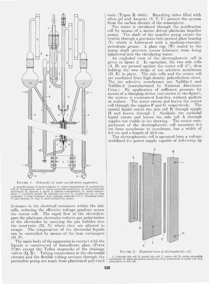
FIGURE 1. Schematic of water pW'ification apparatu8. A, Impeller pump; TI, heat exchanger; 0, center compartment; D, conductivity
cell ; E , thermometer well ; F , cation permeable membrane; G, anion permeable membrane; H , cathod e; I , anode; J, cathode compartment; lC, anode compartment; L, peristaltic pump; lvI , cathodal reservoir; N, anodal reservoir; 0, heat exchanger; P, heat exchanger; Q,R, drainage stopcocks; 8/1\U, breathing tubes; V, glass bearing; W, cup; Z, bead prod uced by pum p.
incr eases in the electrical resistan ce wi thin the side cells, reducing th e effective vol tage gradien t across the cen ter celL The rapid flow of th e electrolyte past the platinum electrodes r edu ces gas polarization of the electrodes by carrying th e gas bubbles in to th e reservoirs (M, N) where they ar e allowed to escape. The temperature of th e electrodal liquids can be con trolled by means of the hea t exchangers (0 , P).
The main body of the apparatus in con tact with the liquids is constructed of borosilicate glass (P yrex 7740) excep t the T eflon stopcocks of the drainage valves (Q, R ) . Tubing connections in the electrodal circuits and the flexible tubing sections t hrough the peristaltic pump are made from plasticized polyvinyl
resin (T ygon R - 3603). Breathing tubes fill ed with silica gel and Ascari te (S, T , U) protect t he system from th e carbon dioxide of the atmosphere.
The wa ter is cir culated through the purification cell by means of a motor driven pIa t inum impeller pump . The shaft of the impeller pump enter s th e system through a precision-bor e ground glass bearing (V) which is lubricated with a m edium-viscosity petroleum grease. A glass cup (W) sealed to th e pump shaft prevents excess lubrican t trom being spla tter ed in to the circulating wa ter .
An exploded view of the electrophoretic cell is given in figure 2. In operation, th e two side cells (A , B ) are pressed against the cen ter cell (C), thus holding the t wo s trips of ion selective m embrane (D , E ) in place. T he side cells and the cen ter cell ar e m achined from high-density polyethylene sheet. The ion selective membran es ar e N alfilm -l and N alfilm-2 (manufactured by National Aluminate Corp .). By application of sufficien t pressure by means of a elamping device (no t s110wn in t1le figure), the system is m aintained leak-fr ee wi thout gaskets or sealan t . The water enters n,nd leaves the cen ter cell through th e nipples F and G respectively . The anodal liquid enters the side cell B through nipple H and leaves through 1. Similarly the cathodal liquid en ters and leaves the side cell A through nipples no t visible in th e drawing. The center com partmen t of the electrophoretic cell measures 0.3 cm from m embran e to membrane, h as a wid th of 0.6 cm and a length of 30.0 cm.
TIle electrophoretic cell is operated from a vol tage stabilized d-c power supply capable of delivering up
F I GURE 2. Exploded view of electrophoretic cell.
A, Cathodal side cell ; B, anodal side cell ; C, center cell; D, cation permeable membran e; E, anion permeable membrane; F,G, connections to center cell ; R,I, conncctions to side cell.
528
to 200 ma between ° and 1500 v. The cell current and volLage arc measured with conventional instrume nLs. Inasmu ch ns Lhe re istance through the side cell j very mu ch lowel" Lhan LhnL Lhrough the water in Lh center cell , Lhe volLnge drop across the center cclli nlll10st idenLical to that ncl"OSS the electrodes. With the cell geomeLry and power supply described above, a voltage grndient or up to 5,000 vlcm can be produced.
3. Procedure and Performance
The ccll constant of the conductivity cell was determined with 0.01 N potnssium chloride solution nt 18 nnd 25 °0 using the method described by Daniels [12] and thc conductivity values of Jones and Brndshnw [13]. The resistance measurements for the cell calibration were made with n calibra ted a-c resistance bridgc (General Radio typc 650- A) capable of being read to within 0. 3 percent. The cell constant was found to be 0.368 em- l with an elTor or ± 0.5 perccnt.
The rcsistance of the watcr in the conductivity cell WitS measured with a calibrated d-c mcgohm resistance bridge (General Radio type 544-BS8) since the polarizntion effect were found to be negligible. The thermometer above the conductivity cell was calibrated by compnrison with a certified standard thermometer. Th e deviation of the temperatme of the water between the electrodes of the conductivity cell and the temperature indicated on the thermometer was investignted by circulating water or constant and high purity through the sys tem while lowering and raising the temperature o( the wnter . Temperature readings were Laken at the mom.ent or bridge balance at unnltered bridge setLings by appronching the resis tance from both iLbove nnd below. The nHtximum tcmpernturc deviation observed for identical conductivities at the rates of temperature change employed in the experimen ts was always smiLlIeI' tlMn 0.15 °0, and nt room. tempernture wns only 0.05 °0. '1'he maximum conductivity error introduced by the temperat ure m easurement was calculnted to be ± 0.5 percent.
A number of precautions were taken to prevent the contaminntion of the water with organic subs tances and to reduce the influx of ions from the surface of the glass. Among these precautions were: (1) B efore operating the purification nppanttus, the glass pnrts were steiLmcd for over 200 hI' in such a way that the s te/un condensed on the inner surfnce of the equipment and washed away ions extracted from the glass; (2) the ion-permeable membranes were converted in to the acid and hydroxyl forms, respectively, and soaked in uccessive portions of distilled water over a period of days to remove water-soluble residues; (3 ) the apparatus was operated several days in advance of an experiment with successive portion s of organic-free distilled water to remove further traces of impuriti es in the apparatus.
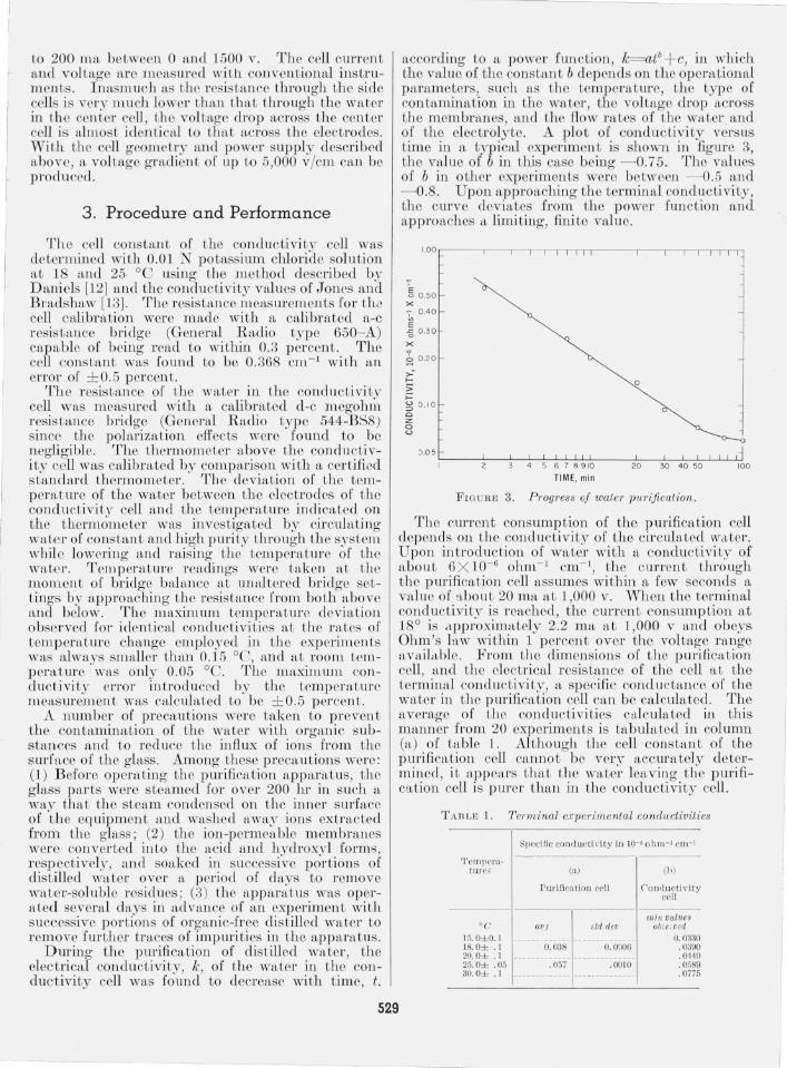
During the purificntion of dist illed water, the electrical conductivity, Ie , of the water in the conductivity cell was found to decrease with time, t.
according to a power function, 1c= CLtb +c, in which the value of the consL/LnL b dep ends on Lh e operational parameters, such fiS the temperature, the type of contiLmination in the ,.vater, the voltage drop across the membranes, and the flow rates of the W/L ter and of the electrolyte. A plot of conductivity vcrsus time in a typiclLI oxp eriment is shown in fig ure 3, the value of b in this case being - 0.75. The values of b in other experiments were between - 0.5 and - 0.. Upon npproaching the terminnl conductivity, the curve deviates from the power fLUlct ion and approaches <1, limiting, fini te value.
~ 0.50 x '7 0.40
E -g 0.30
x ~
~ 0.20-
,.: .... ;; >= ~ 0.10 o z: o '-'
o
~.O 5 '-_--!,----~----L--.l-..L..L..J....LL----L--L--L-..L...L-LLl.J 3 4 5 6 7 8 910 20 30 40 50 100
TIME, min
FIGURE 3. P Togress oj waleT pUTificalion .
The CUITent consumption of the purification cell depends on the conductivity of the circulated water. Upon introduction of water with fi conductivity of about 6 X 10- 6 ohm- l em- l, the current through the purification cell assumes within a few seconds a value of 'Lbout 20 rna at 1,000 v. When the tcrminal condu ctivity is reached, the current consumption at 18° is I'\,pproximately 2.2 rna at 1,000 v and obeys Ohm's law within 1 percent over the voltage range nvailable. From the dimensions of the purificnt ion cell, and the electrical resistance of the cell at the terminal conductivity, n specific conductance of the water in the purification cell C,Lll be ca lculated. Tho nverage of the conductivities calculated in this manner from 20 experiments is tabulated in column (n) of table 1. Although the cell constant of the purification cell cannot be very accurately determined, it appenrs that the water leaving the purification cell is purer thll.l1 in the co nductivity cell .
TABLE 1. T erminal e."Cperimenlal conductivities
TCfl1j)('ra· tu re,:;
°C 15. 0± 0. 1 18. 0± . 1 20. 0± . 1 25. 0± .05 30.0± . I
Speci fic conclurU yity in 1O-6 oh m-1 cm - l
(a)
Puri fi cation cell
av) add,"
O. 038 O. 0006
. 05i . 00 10
(b )
('on<luct i\"i ty cell
min values ob:e;v,d
O. 03:m . 0390 .0440 . 0589 . 0775
529
4. Results and Discussion
Using the precautions outlined earlier it takes approximately 1 hr to approach a terminal conductivity after fIlling the apparatus with a good grade of distilled water. The terminal conductivity of the most successful of 20 experiments is tabulated in column (b) of table 1. E ach value is subj ect to an es timated error of ± 1 percent. Prolonged operation of the apparatus over extended periods will not yield a water of higher purity than obtained after about 2 hI's.
The conductivities of ultra low-conductivity water reported by various researchers are given in table 2. For a better comparison the concentration of a solution of sodium chlorid e is calculated which would possess a specifIc conductivi ty corresponding to the reported values. These equivalent concentrations are given in table 2. The values are calculated using a theoretical conductivity of pure water equal to 0.0371 X 10- 6 ohm- 1 cm- 1 at 18° and 0.0549 X 10- 6
ohm- 1 cm- 1 at 25°. These values are calculated using the recent tabulations of the ionization constant and
equivalent conductivities of the H + and OH- ions given by Robinson and Stokes [23].
Kohlrausch and H eydweiller [1] obtained their water after 36 consecutive distillations in a vacuum and measured its conductivity in a fused silica cell which had been exposed to water for 10 yr. (Attempts by N ernst to reprocluce this value were unsuccessful [24]). Kunin and McGarvey [20] r eport on water from a mono bed ion exchange column although the temperature is not given . Those workers who used distillation methods incorporated one or more of the following modifIcations: (1) Distillation from an alkaline permanganate solution, (2) purging the solution and/or the distillate in the column with an inert gas to remove carbon dioxide, (3) use of materials of construction such as tin or organic substances to reduce miner al content.
The apparatus described by the present authors affords a method to produce water of lower ionic cont,ent than any previously r eported in the literature. It is expected to be particularly applicable where it is desired to conduct experiments with small quantities (10 to 50 ml) of extremely ion-free water.
TABLE 2. Data on ultra low-conductivity water, vbtained b!J various workers
Worker
This worL ____ _____ _______________ {
Kohlrausch and I-Teydweiller [1] - _ .. __ { Bengough, Stuart, and Lee [1 4] __ __ __ _ Kraus and D exter [1 5] ___ _ .. _________ _ Weiland [16] __________________ ____ _ Bencowitz and H otchkiss [17] _ _ ____ _ Thiessen an d H errman n [18] ________ _ Kunin and McGarvey [19] -----------Gostkowski [20] ___________________ _ Hulett [21] _____ __ _________________ _ Bourdillon [22] __ _______ ___________ _
Pure water (theoret ical) ______ __ _____ {
5. References
Conductivity in 10-6 ohm-1 cm- l
O. 0390 .0589 . 0429 .062 . 045 .048
O. 053 to O. 066 .06 to . 07
. 065 to . 080 O. 07
. 07
. 081
. 086
. 0371
. 0549
. 0111
[1] F . Eohlrausch and A. Heyd\\"eiller, Wied. Ann . 53, 209- 235 (1894) ; Z. ph ysik. Chem . H, 317- 330 (1894).
[2] F . Bergsma, Chem . Weekblad 48,361- 364 (1952). [3] W. F . Langelier, J . Am. Water Works Assoc. 44, 845- 848
(1952). [4] S. G. Wiechers a nd C. Van Hoek , R esearch 6, 192- 194
(Hl53). [5] R. E. E liassen, Civil Eng. 24, (no. 6) 44- 47 (1954). [6] A. G. Winger et al. , Ind. Eng. Chem. 47, 50- 60 (1955). [7] P . H. Pra Ll snitz, Glas nnd K eramische Filter, Akad.
Verlagsgesellschaft MBH, Leipzig, p. 151 (1933). [8] H . W. Morse and G. W . Pierce, Z. physik. Chem. 45,
589- 607 (1903). [9] Ie. H. Meyer and W . Straus, H elv. Chim. Acta 23,
795-800 (1940). [10] T. R. E. Kressman, Nature 165, 568 (1950). [11] W . Juda and E. A. Mason, Chem. Eng. Progr. 55, 155- 162
(1959) . [12] F. D a niels et al. , Experimental Physical Chemist ry,
pp . 163, 459 (Mc Graw-Hill Book Co., Inc. New York, N.Y., 1949).
Tem perature
°C
Concentr. of a sodium cbloride solution in ppm with same conductivity
18__ _________ 0. 0010 25 ___________ . 001 8 18 .. __ . ____ . __ .0031 25 ___________ .0032 18_________ __ . 0043 18___________ . 0059 18______ _____ 0. 0086 to O. 0156 Not given ______________ _________ _ 25 ____ _______ . 0046 to. 011 8 Not g iven _________ ______________ _ 0_ _ _ _ _ _ _ _ _ _ _ _ O. 0280 Not given _______________ ________ _ 18___________ .0260 1 8 _ _ _ _ _ _ _ _ _ _ _ . 0000 25_ _ _ _ _ _ _ _ _ _ _ . 0000 0_________ ___ . 0000
Method of purification
} Electrophoresis.
} Distillat ion . Do . Do. Do. Do. Do .
Ion exch ange. Distillation.
D o. Do .
[13] G. J ones a nd B. C. Bradshaw, J. Am. Chern. Soc. 55, 1780- 1800 (1933).
[14] G. D . Bengough, .J. M . Stuart and A. R . Lee, J . Chem. Soc. 1927, 2156- 2161.
[15] C. A. Kraus and W. B. D exter, .J. Am. Chern . Soc. 44, 2468- 2471 (1922).
[16] H. J . Weiland, J. Am. Chem . Soc. 40, 131- 150 (1918). [17] I. Bencowitz and H . T. Hotchkiss, Jr., J . Phys. Chem. 29,
705- 712 (1925). [1 8] P . A. Thiessen and Ie H errmann , Chem. Fabrik 10, 18
(1937). [19] R. Kunin and F. McGarv ey, Ind. Eng. Chem. 43, 734- 740
(1951 ) . [20] K. Gostkowski , Z. physik. Chem . 170, 149- 152 (1934) . [21] G. A. Hulett, Z. physik. Chem. 21, 297- 301 (1896). [22] R . Bourdillon,.J. Chern. Soc. 103, 791- 795 (191 3) . [23] R . A. Robinson and R . H . Stokes, Electrolyte Solutions,
2d ed. (Academic Press Inc ., New York, N.Y., 1959). [24] H . S. T aylor, A Treatise on Physical Chemistry 1, (D. Van
Nostrand Co., New York, N.Y. 1925) (see fo otnote p. 521).
(P aper 64A6- 76)
530


![A method for determining electrophoretic and …...[4,5]. Current techniques for measuring electrophoretic mo-bility include an electroacoustic method [6], electrophoretic light scattering](https://img.pdfslide.net/doc/110x75/5f08e22b7e708231d4242f99/a-method-for-determining-electrophoretic-and-45-current-techniques-for-measuring.jpg)