Embed Size (px)
Citation preview

Ultra-Short-Pulse Laser Technology and Applications: Lecture 5
153
Lectures on
Ultra-Short-Pulse Laser Technology and Applications
Fifth Lecture
Applications: materials processing, dental lasers, optical coherence tomography,
nonlinear microscopy, rapid-prototyping
5.1 Three general aspects of applications 155 5.2 High temporal resolution by optical pump-probe
experiments 156 5.3 Material ablation by ultra-short pulses 159 5.4 Medical applications of ultra-short pulses 168
5.4.1 Applications to hard-tissue ablation in dentistry 168 5.4.2 Applications to soft-tissue ablation: examples 177 5.4.3 Optical coherence tomography using ultra-short pulses 178 5.4.4 Three-dimensional resolution by non-linear interactions
within the focus of ultra-short pulses 183 5.4.5 Advanced applications in optical communications 186
References (Lecture 5) 187

Ultra-Short-Pulse Laser Technology and Applications: Lecture 5 154
Ultra-Short-Pulse Laser Technology and Applications: Lecture 5
155
5.1 Three general aspects of applications
Modern applications of ultra-short (i.e. picosecond and femtosecond) laser pulses
represent a fascinating wealth of new options becoming more and more mature, also
for commercial use. One may divide them into three categories according to the
dominant feature for the specific type of application, some of them being already
discussed above:
• Ultra-short time duration
• Ultra-broad spectral bandwidth
• High-average power
Ultra-short laser pulses of even modest average power in the tens of mW regime
permit outstanding temporal resolution reaching down to the sub-fs time domain.
Amplified pulses of shortest duration (i.e. nowadays few-cycle duration) allow the
most efficient generation of ultra-short wavelengths in the XUV and X-ray re-gime, especially when carrier-envelope phase-stabilized, as was shown earlier in
chapter 4.3. Ultra-high intensities can be attained with setups of table size giving
the opportunity to discover a new regime of non-linear optics associated with much
higher photon energies than in the visible, also explained in detail in chapter 4.
Another aspect of application is quite new, whereby the ultra-short laser is only a tool
for the generation of extremely broad spectra organized in well-defined and equally spaced frequencies represented by the longitudinal modes. On this basis, optical frequency standards have been revolutionized, as was explained in chapter 4.1. In
case of solely taking advantage of the short coherence length associated with ultra-
short pulses, optical coherence tomography (OCT) allows unprecedented three-dimensional imaging. This aspect of application will be discussed below. Even
ultra-broadband communication takes advantage of the high number of well-defi-
ned longitudinal modes in ultra-short pulse lasers.
High-average power systems represent a new tool for efficient and precise manu-facturing of even hardest materials without the necessity of resonantly absorbed
wavelengths creating negligible damage to the surrounding and remaining material
which can be of anorganic or biological nature. Taking advantage of non-linear
Ultra-Short-Pulse Laser Technology and Applications: Lecture 5 156
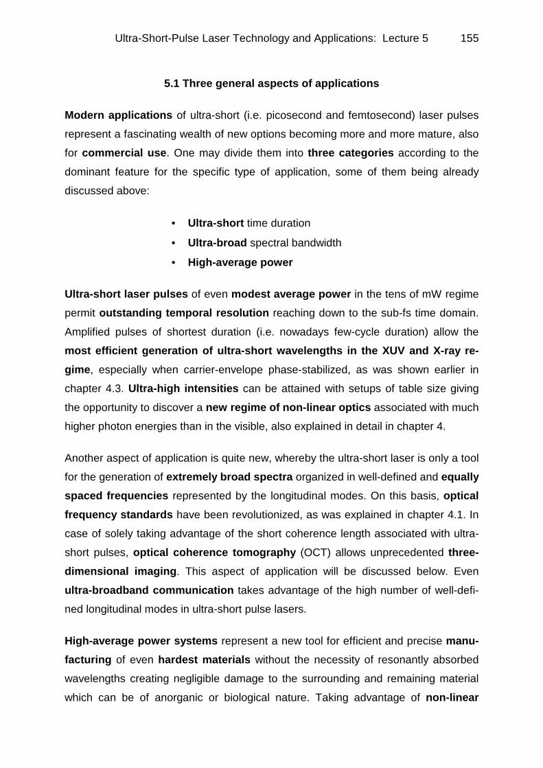
Fig.5.1: Optical pump-probe experi-ment of the absorption dyna-mics as an example for the application of ultra-short pul-ses for time-resolved measu-rements in the 20 ps-regime. PR prism, RR retroreflector, PM photomultiplier, PO polarizer
processes confined to the focus of a mode-locked train of ultra-short pulses yields
the possibility of three-dimensional resolution, being well-known in non-linear microscopy since some time, but representing an innovative solution to three-di-mensional structuring within the context of rapid-prototyping.
5.2 High temporal resolution by optical pump-probe experiments
Fig.5.1 shows an example of a pump-probe experiment (compare the lecture notes
“ultra-short light pulses”, chapter 7 Applications) for the measurement of absorption
dynamics in a semiconductor performed by the author [1]. The experiment involved
an actively mode-locked Nd:YAG laser emitting ~80 ps pulses whose repetition rate
in the order of 80 MHz was reduced by a modulator. The pulse duration was control-
led simultaneously by a specially designed autocorrelator for long delays of more
than 1 ns [2]. In a beam splitter about 90% of the power was separated to form the
pump beam propagating along the path through a λ/2-plate and a chopper to become
recombined with the probe beam which travelled via a folded delay stage to become
collinear with the pump again in second beam splitter. Both beams, being orthogon-
ally polarized with respect to each other, were focused onto the sample. The pump
beam increased the carrier density by becoming absorbed, but very shortly after,
bleaching started to be effective by absorption saturation. The probe beam transmit-
ted through the sample (its contribution to absorption was considered to be negligib-
le) which could be delayed by up to 1 ns, allowed to measure the amount of bleach-
ing being effective at any time within the measurement time span. For this purpose, a

Ultra-Short-Pulse Laser Technology and Applications: Lecture 5
157
Fig.5.2: Bleaching of the absorption in GaAs dep-ending on carrier density. Full lines, measuement data, dotted lines, numerical simulation in order to yield parameters A (Auger), B (bimolecular) and C (normal recombination)
polarizer filtered out the transmitted pump light and, additionally for the increase of
measurement accuracy, a lock-in technique in association with the chopper was
employed. The time resolution of this experiment was ∼∼∼∼ 20 ps being not outstanding
but sufficient for the problem. Fig.5.2 exhibits the typical result of such a measure-
ment: the graphs collected at
different intensities represent
the evolution of bleaching in a sample of GaAs. From
this finding, via a rather com-
plicated numerical iterative
evaluation procedure, based
on the basic formula for the
lifetime of carriers decaying
by three different processes
given in the figure, the Auger recombination coefficient could be derived. This was a
quite important problem at
that time when attempts
were made to explain the
much stronger time-depend-
ence of the threshhold cur-rent in quaternary semi-conductor lasers (of the
type GaInAsP employed in
the communication business) with respect to GaAs diode lasers. The answer yielded
by such experiments to the question which became widely known as T0-problem
was the much higher Auger recombination efficiency represented by the coefficient A
being a material property [3]. It could only become reduced by lowering the carrier
density at threshold by chosing semiconductor media of higher gain like quantum
wells.
Fig.5.3 depicts another type of time-resolving measurement technique: the cross-correlation method. In this case, the effect of two ultra-short pulse laser beams on a
sample is studied under a varying temporal delay relative to each other. The signal

Ultra-Short-Pulse Laser Technology and Applications: Lecture 5 158
Fig.5.3: Time-resolving measurement of lumines-cence in GaInAs by cross-correlation of 100 fspulses of a CPM dye laser with λ ≈ 620 nm. The achievable time resolution is around 10 fs.
Fig.5.4: Pump-probe measurement of the „tunneling time“ of optical pulses through multilayer dielectric mirrors yielding an accuracy better than 0.3 fs
yielded by the consecutive or
cumulative effect of the be-
ams is taken and accordingly
evaluated. In the case of this
figure, the correlation signal
of luminescence in two GaInAs samples, one being
undamaged and the other af-
ter He+ bombardement, was
studied with respect to time
delay. The laser employed
was a CPM dye laser with
λ ≈ 620 nm and a pulse dur-
ation τ = 100 fs. The result-
ing time resolution in this ca-
se is in the order of ∼ 10 fs [4].
A record temporal resoluti-on at the time this work has
been carried out, is illustra-
ted in Fig.5.4. It reveals the
setup of a measurement of
the “tunnelling time” of op-
tical pulses through multilayer dielectric mirrors (1D photonic bandgaps) [5]. In this
case, being easily understandable with respect to the measurement procedure, the
accuracy was better than 0.3 fs de-
monstrating the capacity of sub-fem-tosecond resolution for ultrafast spectroscopy. The result demanding
the propagation of a pulse faster than
the speed of light has been a very hot

Ultra-Short-Pulse Laser Technology and Applications: Lecture 5
159
Fig.5.5: Price of diode laser optical po-wer versus year (extrapolation for 2005)
topic for a certain time. The explanation is centered on the fact that the pulse is atte-
nuated by about 100 times in an asymmetric way so that shifts of the pulse center
contribute to the speed of propagation.
5.3 Material ablation by ultra-short pulses
Ablation, i.e. vaporization of material without substantial heating of the bulk, was
successfully tested with all kinds of matter so far. Hence this method allows to shape
metals, semiconductors and insulators as well as biological substance leading
to interesting aspects for commercial applicability. This aspect puts several limiting
requirements onto the source of the ultra-short pulses, i.e. the mode-locked laser.
1. Compactness: e.g. 40 × 40 × 30 cm3
2. Moderate cost: e.g. ≤ 50 000 €
3. Design: simple, robust, stable
4. Relevant specifications:
• pulse length
• wavelength
• average power
• repetition rate
• pulse quality and stability
Besides important aspects of laser oscillator and amplifier design, as they have been
discussed in detail in the previous chapters, the price of diode laser optical pump power is a major limitation. This is illustrated in Fig.5.5 following data and estimati-
ons by D. Scifres of Spectra Diode
Labs (SDL) [6]: the price of diode pump
power is plotted versus the year indi-
cating a decrease in $/Watt of 60% per
year. This allows a very optimistic ex-trapolation of 1 $/W to be reached
around 2005. It might be a question of
precision for such a forecast, but there
is no question that such values are
going to be reached. Unfortunately,

Ultra-Short-Pulse Laser Technology and Applications: Lecture 5 160
Fig.5.6: Femtosecond ablation of metals by (a, top) femtosecond and (b, bottom) nanosecond pulses
according to Momma et al. [7].
prices for diode-pumped solid-state laser like Nd:YAG of today are still higher than for
flashlamp-pumped ones.
For many industrial fabrication processes the shaping of metals is of great import-
ance. A very impressive comparison between the effect of femtosecond pulses drilling holes in steel and nanosecond pulses of even higher energy is depicted in
Fig.5.6a und b [7]. The main advantage of the ultra-short pulse application can be re-
cognized very easily: it is the
regularly shaped crater rims with no trace of dam-age in the surrounding ma-
terial. In more scientific
terms, there is no evidence
of thermal or shock-wave
collateral damage. The low-
er figure illustrating the im-
pact of the ns pulses dem-
onstrates just the contrary.
Nevertheless, there is still
discussion on this issue fac-
ing the experimental result
that under specific circum-
stances even ns pulses may
yield smooth craters and
surrounded by absolutely
unmolten material, as shown
in Fig.5.7 [8].In general, sub-picosecond pulses are the
ones of choice for achieving
the best results in case that
the fluence onto the focal
area is selected carefully not
overheating the material
leading to heat diffusion by hot carriers into the surroundings. Fig.5.8 representing a
result of Laser Zentrum Hannover (by S. Nolte and B.N. Chichkov) demonstrates the
Ultra-Short-Pulse Laser Technology and Applications: Lecture 5
161
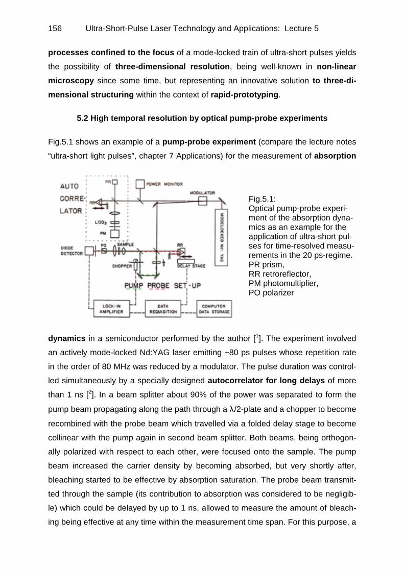
Fig.5.7: Laser ablated nozzle plate com-prising an array of 500 nm diameter slant holes at 20° to surface. τp = 20 - 40 ns, kHz repetition rate (Knowles et al. [8])
Fig.5.8: Microstructuring of tungsten by laser ablation with pulses of τp = 100 fs, Ep ≈1mJ, kHz rep. rate, λ=780 nm (Courtesy S. Nolte, B.N. Chichkov, Laser-Zentrum Hannover, Germany)
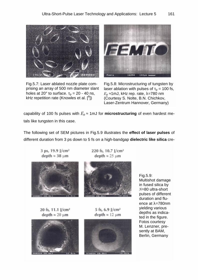
Fig.5.9: Multishot damage in fused silica by N=80 ultra-short pulses of different duration and flu-ence at λ=780nm yielding various depths as indica-ted in the figure. Fotos courtesy M. Lenzner, pre-sently at BAM, Berlin, Germany
capability of 100 fs pulses with Ep ≈ 1mJ for microstructuring of even hardest me-
tals like tungsten in this case.
The following set of SEM pictures in Fig.5.9 illustrates the effect of laser pulses of
different duration from 3 ps down to 5 fs on a high-bandgap dielectric like silica cre-

Ultra-Short-Pulse Laser Technology and Applications: Lecture 5 162
ating multi-shot damage [9]. The different shapes of the ablation craters depicted
in the four micrographs can be clearly seen. Picosecond ablation yields a very irregu-
lar hole, while shorter and shorter pulses give rise to eventually completely smooth
holes as the last photograph shows being created by the shortest 5 fs pulses.
Laser-induced breakdown resulting in damage to dielectrics has been subject of
extensive experimental and theoretical investigations since powerful lasers became
available [10,11,12]. It has been described in terms of three major processes: (i) the
excitation of electrons in the conduction band by impact and multiphoton ioniza-tion (MPI), (ii) heating of the conduction-band (hencefourth free) electrons by the
radiation, and (iii) transfer of the plasma energy to the lattice. For pulses of a few
picoseconds or shorter, heat diffusion is “frozen” during the interaction [13] and the
shock-like energy deposition leads to ablation.
Experiments being the background for Fig.5.9 by Lenzner et al. were carried out at
Photonics Institute a few years ago [9] as a comparison of two isotropic dielectrics,
fused silica (FS, Corning 7940), and barium aluminium borosilicate (BBS, Cor-
ning 7059). The surfaces of the samples were formed by a direct drawing process
from the melt; resulting in a residual surface roughness of < 13 nm. The bandgap
energies of the two materials are Eg ≈ 9 eV and Eg ≈ 4 eV, respectively. For a quan-
titative evaluation of ablation, the samples were investigated by light and scanning
electron microscopy. In order to make the ablated volume per pulse Va and the ab-
lation depth da accurately measurable, each site was exposed to 50 pulses at a given
fluence. As an example, Fig.5.10 depicts Va versus on-axis fluence F for two different
pulse durations in FS. The linearity of Va(F) is striking and found to be a general fea-
ture for the entire pulse width regime studied. This characteristic can be utilized for
determining the damage threshold fluence Fth by extrapolating the regression line
of Va on F to Va = 0. Fig.5.11 shows Fth determined in such a way for pulse durations
between 5 ps and 5 fs in FS and BBS. The error bars depict relative (random) errors,
the absolute (systematic) error of the measurements was less than ±15%. Figs.5.12
and 5.13 show the accumulated ablation depth as a function of the number of laser
shots for FS and BBS, respectively, revealing important differences (A) and similari-
ties (B) in the behavior of the two materials. (A) The comparable slopes of the regres-
sion lines in Fig.5.12 yield ablation depths da that exhibit hardly any dependence on

Ultra-Short-Pulse Laser Technology and Applications: Lecture 5
163
Fig.5.10: Volume Va of fused silica ablat-ed by one laser pulse versus energy flu-ence F for two different pulse durations
Fig.5.11: Threshold fluence in FS and BBS versus τ at λ = 780 nm. Each site was irradiated by 50 laser pulses [9]
the pulse duration in FS. In strong contrast, such a τ invariance is limited to the sub-
picosecond regime in BBS (Fig.5.13), whereas da rapidly decreases for decreasing
pulse durations as τ approaches the 10 fs regime. The reproducibility of ablation is,
in both materials, substantially higher in the 10 fs regime than in the subpicosecond
regime.
A few years ago, Stuart et al. [14] derived a simple rate equation for the evolution of
a free electron density n(t) in a dielectric medium exposed to intense laser radiation,
dn/dt = αI(t)n(t) + σkIk, (1)
where I(t) is the intensity of the laser pulse, α is the avalanche coefficient, and σk is
the k-photon absorption cross-section with the smallest k satisfying kћω ≥ Eg, where
ω is the laser angular frequency. The energy of the free electrons heated by the laser
is subsequently transferred to the lattice. This energy transfer leads to the ablation of
the heated zone, which is the major manifestation of femtosecond optical breakdown.
The experimental observations could be consistently interpreted in terms of Eq. (1).
Fth can be predicted by postulating a threshold electron density nth associated with
the onset of permanent damage and solving the rate equation. In strong contrast with
long-pulse damage, the density of seed electrons for the avalanche does not have to
be postulated because it no longer relies on thermal excitation of impurity states, but

Ultra-Short-Pulse Laser Technology and Applications: Lecture 5 164
Fig.5.12: Ablation depth in fused silica FS for increasing number of pulses and different pulse durations, measured at fluence levels of 5±J/cm2 [9].
Fig.5.13: Ablation depth in barium aluminum borosilicate BBS for increa-sing number of pulses and different pulse durations at fluence levels of 6.2±0.7 J/cm2 [9].
can be produced by MPI with rapidly increasing efficiency for decreasing pulse dura-
tion. The dramatically increased reproducibility of ablation in the 10 fs regime report-
ted above is a direct consequence of the strongly increased deterministic seed elec-
tron production for the avalanche (Fig.5.9 basically illustrates this finding in a two-di-
mensional way). Another interesting finding derived from theory applies just for 5 fs
pulses, where photoionization is dominated by tunnelling as the breakdown threshold
is approached at this pulse duration.
Quantitative prediction of the penetration depth of the incident radiation, and hen-
ce that of da, would call for solving the coupled rate and wave equations for n(t,z)
and E(z,t). Nevertheless, the influence of the pulse duration on da, which is expected
to scale inversely proportional to the free electron density, can be qualitatively asses-
sed by inspecting rate Eq. (1). For a regime in which carrier generation is dominated
by impact ionization, Eq. (1) predicts an electron density, and hence da, that is in-
dependent of τ at a fixed fluence. By contrast, in an MPI-dominated regime, da is
expected to rapidly decrease for decreasing pulse durations (at F is constant). The
theoretically accessible values of the avalanche and MPI coefficients allow predicting
the qualitative behavior of da (τ) and its comparison with the data in Figs.5.12 and
5.13. The fraction of the critical density produced by photoionization at F = Fth is
calculated as np(500 fs)/nth ≈ 4×10⁻⁸ and np(50 fs)/nth ≈ 1.5×10⁻⁴ for FS, and

Ultra-Short-Pulse Laser Technology and Applications: Lecture 5
165
Fig.5.14: Scheme of interaction of laser pulses with a metal exciting first the elec-tron gas which is coupled to the lattice in a delayed fashion
np(500 fs)/nth ≈ 0.09 and np(50 fs)/nth ≈ 0.35 for BBS. These data suggest that opti-
cal breakdown in fused silica is dominated by the avalanche process down to the
10 fs regime, whereas in BBS having much smaller bandgap, multiphoton ioniza-tion takes over for pulse durations below 100 fs. This finding is conclusively confir-
med by the data in Figs.5.12 and 5.13. As a matter of fact, da is virtually independent
of pulse duration for FS in the entire femtosecond regime. In BBS, this applies only to
the subpicosecond regime, with da becoming subject to a rapid decrease with de-
creasing pulse duration for τ approaching the 10 fs regime. These results show that,
even for a bandgap as large as ∼ 9 eV, MPI produces some 10 orders of magnitude
higher seed electron density in the 10 fs regime than available in thermal equilibrium.
As a result, sub-10 fs laser ablation can be accomplished with a precision correspon-
ding to a few tens of atomic layers. Maybe this will allow precise microstructuring
in the future also for dielectrics by applying 10 fs pulses in the mJ regime.
The comparison of ablation results for
metals and dielectrics given above
clearly reveals the fact that the former
are much easier to shape by ablation
as sufficient densities of free elec-
trons to be heated are around. For a
quantitative treatment, there exist a
number of theories of different com-
plexity to describe the relevant para-
meters. In the following, a simple two-temperature model [7] is pre-
sented by its basic aspects. Fig.5.14
schematically depicts the situation where laser radiation penetrates a solid thereby
first heating the electrons. The hot electron gas is coupled (via a coupling coefficient
γ) to the lattice transferring thermal energy there. Of course, the electron gas may
also loose heat via diffusion, especially via hot electrons. Eventually, the lattice un-
dergoes ablation as soon as the temperature exceeds the boiling point, and hence
atoms being expelled off the surface. The table in Fig.5.15 contains the coupled rate
equations for electron temperature Te and lattice temperature Ti based on the
heat balance in the electron gas (1) and the lattice (2). All the symbols used are ex

Ultra-Short-Pulse Laser Technology and Applications: Lecture 5 166
Fig.5.16: Ablation depth per pul-se versus fluence for Ti:sapphire laser pulses with λ = 780 nm and τp = 150 fs. The lines repre-sent the best fits to the corres-ponding equations in Fig.5.15 indicating two ablation thres-holds and efficiencies.
Fig.5.15: Metal ablation:Theoreti-cal des-cription by a simple two-tem-perature model [7]
plained in the figure. There exist two special solutions of these coupled differential
equations: in the first case, the characteristic diffusion length of electrons l is much
smaller than the optical penetration depth δ. In the second case l is much larger than
δ. This fact yields different ablation efficiencies as depicted in Fig.5.16. Calculations

Ultra-Short-Pulse Laser Technology and Applications: Lecture 5
167
based on the formulae derived above show the following corresponding results for
two cases of different laser specifications:
Ablation Depth in Metals
Pulse energy 10 µµµµJ, repetition rate 1 MHz, average power 10 W
Focal diameter d ∼ 10 µm d ∼ 50 µm per pulse per ms per pulse per ms
Al 320 nm 0.32 nm 43 nm 43 µm Au 310 nm 0.31 nm 36 nm 36 µm Cu 270 nm 0.27 nm 13 nm 13 µm
Pulse energy 1 mJ, repetition rate 10 kHz, average power 10 W
Focal diameter d ∼ 10 µm d ∼ 50 µm per pulse per ms per pulse per ms
Al 710 nm 7.1 µm 430 nm 4.3 µm Au 700 nm 7.0 µm 430 nm 4.3 µm Cu 640 nm 6.4 µm 380 nm 3.8 µm
In case the average power is kept constant, the results suggest to employ rather
higher repetition rates and smaller pulse energies to achieve the best ablation
efficiency. Of course, the repetition rate is limited by the time, the ablated plasma
plume needs to leave the area of laser irradiation yielding an upper limit for repetition
in the regime between 100 kHz and 1 MHz.
Fig.5.17a and b shows two other examples of high-precision ultra-short pulse ma-chining of metals, in this case of copper: (a) represents a scanning electron micro-
graph of a micro-gear wheel out of Cu. (b) demonstrates the reproducibility of abla-
tion by femtosecond pulses.
Fig.5.17: Femtosecond ablation of copper: (a, left) scanning electron micrograph of a micro-gear wheel. (b, right). Array of holes in order to demonstrate the repro-ducibility. λ = 390 nm, τp = 120 fs, F = 0.8 J/cm2, number of pulses N = 5000 [7]

Ultra-Short-Pulse Laser Technology and Applications: Lecture 5 168
5.4 Medical applications of ultra-short pulses
5.4.1 Applications to hard-tissue ablation in dentistry
Already shortly after the first demonstration of the laser in the year 1960, first at-
tempts to ablate dental hard-tissue were undertaken. As soon as in 1967, however,
it became evident that ruby, Nd:YAG and CO2 lasers are not suitable for such appli-
cations because by their interaction a damaging temperature rise within the pulp oc-
curred. Hence, only dental technologic applications (prosthesis etc.) of these lasers
could be successfully carried out. The critical limit for a reversible temperature rise
within the pulp lies around 5°C above body temperature. If this limit is exceeded irre-
versible damage is caused [15].
The Ho:YAG and the Er:YAG became the next candidates for dental lasers. Becau-
se of the danger of overheating the pulp they are only used in a pulsed mode mostly
under application of a cooling water spray onto the location of treatment on the tooth.
The pulse durations thereby are in a range between 4 µs and several 100 µs and the
repetition rates typically are around 1-20 Hz. While the laser energy in case of the Er-
laser predominantly is coupled in via absorption of water within the dental hard tis-
sue, in case of the Ho-laser due to the weaker coupling of radiation to water absorp-
tion mostly thermal ablation takes place. Therefore, already in 1993 this type of
laser was considered to be not suited for the treatment of dental hard tissue.
The wavelength of the Er-laser is located close to an absorption maximum of water
thus allowing to couple energy into the dental tissue very effectively. Thereby, via im-
mediate heating and vaporization of the water content within the focus on a tooth,
micro-explosions take place blowing out pieces of tissue [16]. By this approach, ab-
lation rates become feasible which allow practical application of this technology. As-
sociated with this mechanism of ablation, however, micro-cracks within the dental
hard-tissue occur penetrating down to 0.3 mm depth within the tooth. Conventional
turbine based cavity preparation, for comparison, only causes cracks up to 0.02 mm
depth.
Already at the beginning of the 1990s, investigations on ablating dental hard tissue
(enamel and dentine) were carried out with ultra-short pulses [17,18,19] involving
pulse durations around 30 ps. The results achieved with respect to shape of faces,

Ultra-Short-Pulse Laser Technology and Applications: Lecture 5
169
quality of the crater rims and absence of damage within the remaining material (key
issues: free of cracks as well as of molten, re-solidified zones along rims and faces of
cavities) were clearly superior to conventional IR laser systems. In case of suitably
selected parameters even complete absence of damage could be achieved. The rea-
son for this improvement can be seen in plasma-induced ablation, whereby dental
tissue is not removed by sudden vaporization of water as described for the case of
conventional IR laser systems, but via direct plasma formation and the consecutive
expulsion of material. The associated shock waves and the thermal load are signi-
ficantly smaller than in conventional laser cavity preparation. The mechanisms of plasma-induced ablation are as follows: at power densities >1011 W/cm² obtainable
routinely with ultra-short pulses of sufficient pulse energy at suitable focusing condi-
tions, an electric field of >107 V/cm is generated at the focus spot. A micro-plasma is
induced with an absorption coefficient much higher than that of enamel. Conse-
quently, the laser beam is absorbed totally by the plasma. The ablation itself is caus-
ed by the ionization of the enamel and the shock wave generated by this. The validity
of this model was proven by numerous publications and consequently elaborated for
the regimes of femto-, sub-pico- and picosecond pulse durations. In comprehensive
studies the interaction of ultra-short pulses with dental tissue and the ideal parame-ters for ablation were investigated. Thereby, out of reasons of system availability,
predominantly results covering the time interval between 120 fs and a few ps as well
as above 20-25 ps were reported. Spatial scanning over the area to be treated, hav-
ing been employed by some research groups right from the beginning on in order to
make handling for the dentist more efficient as opposed to small focal areas, was
soon also requested out of more scientific reasons, because laser shots impacting
repetitively onto the same spots yield unfavorable heat distribution and cavity shapes
[20] being undesirable in practical applications.
The details of ultra-short pulse tissue interaction are as follows:
i) Plasma formation by the impact of ultra-short pulses
The incident electromagnetic field of the laser radiation causes an avalanche-like generation of free electrons. The laser energy is absorbed that rapidly within the
material so that at pulse durations of ∼ 10 ps and less hardly any thermal or hydro-dynamic response can take place. The value of the fluence leading to the formation
of a plasma depends on several factors, like the wavelength, pulse duration, physical

Ultra-Short-Pulse Laser Technology and Applications: Lecture 5 170
Fig.5.18: Observed values of damage threshold for fused silica at λ = 1053 nm (full circles) and 825 nm (full triangles), and CaF2 at λ = 1053 nm (full squares). Solid lines are τ1/2 fits to long pulse results. Estimated absolute error in data is ± 15% [22].
tissue parameters and defect density [21]. Models to calculate the relevant quantities
in case of dental hard tissue follow quite exact calculations performed on silica as-
suming a situation matching to an insulator in many respects. Fig.5.18 gives relevant
data on damage threshold for fused silica at λ = 1053 nm and 825 nm as well as for
calcium fluoride CaF2 at λ = 1053 nm [22]. The trigger for the plasma formation is the
high intensity I of the incident radiation (starting at ∼ 0.1-10 TW/cm²). At such values
multi-photon absorption (MPA) is very likely to occur. A valence electron can gain
enough energy by the absorption of several photons (e.g. 8 for fused silica, 6 for
water @ λ = 1 µm) resulting in an effectively free electron. The probability for the
simultaneous absorption of m photons scales as Im also making the process quite
confined. The free electron faces additional acceleration in the electromagnetic field
of the laser pulse creating a hot electron. Collisions with the surrounding atoms lead
to impact ionization causing an avalanche process to start. Even transparent media
become highly absorbing in this way. In general, an initial electron concentration n0 is
present in all materials, especially in dental hard tissue. It can be easily shown (simi-
larly to description above)[23] that n0 is unimportant if it is small compared to the ratio
of the MPA source term to the avalanche rate. This is always the case due to the
high nonlinearity if I is sufficiently high. The electric conductivity can be derived in a
simplified model by assumptions on the electron-phonon coupling and hence on the
mobility of electrons being comparable in silica and dental enamel. According to the
Wiedemann-Franz law the thermal and the electric conductivity are mutually propor-
tional thus allowing to approximate the thermal diffusivity. Quantitative results of the
model thus are: the thermal diffusion length for heat induced by a 1 ps pulse is on
the order ~0.01 µµµµm in biological tissue. Hence no heat conduction for pulses with

Ultra-Short-Pulse Laser Technology and Applications: Lecture 5
171
Fig.5.19: Distribution of the absorbed laser energy density in di-rection of the beam for 4 different pulse durations in dental hard-tissue. The flu-ences were assumed to be 10% above ablation thres-hold. Nearly all the energy is deposited within a layer of 1 µm (λ = 1053 nm, µa li-near absorption coefficient)
Fig.5.20: Generation of free elec-trons (a) solely via MPA (dotted line) and (b) via MPA and impact ionization together (full line). The incident laser pulse is shown by the broken line for reference [23].
durations < 1 ps may be assumed (for comparison the mean-free path of an electron
in Si is ~1000 times larger, hence the corresponding diffusion length ~1 µm).
ii) Ultra-short pulse propagation in dental material
The propagation of an ultra-short laser pulse within a material in this context is gover-
ned by absorption and reflection at the layer of plasma generated by the pulse it-
self. Absorption is described in this case (when neglecting reflection as a first step)
by the dissipated energy per time employed for the generation of free electrons. Mea-
surements like the ones depicted in Fig.5.19 for fluences 10% above the ablation
threshold show that the values of absorption throughout the whole range of depths
within tissue do not differ significantly for pulse durations between 0.5 ps and 10 ps.
For all pulse durations within this regime nearly the whole energy is deposited within
a layer of ∼ 1 µm thickness [24].

Ultra-Short-Pulse Laser Technology and Applications: Lecture 5 172
Fig.5.21: The generation of high electron densities yields reflection of the laser pulse by the plasma. The full line depicts the intensity trans-mitted into the tissue un-derneath the plasma layer. The dotted line represents the shape of the incident pulse for reference [21].
Fig.5.20 describes the evolution of electron density at the material surface for a
pulse close to ablation threshold. From the quasi-parallel onsets of curve (a) and (b)
within the rising part of the pulse it becomes evident that MPA within the ultra-short
pulse temporal regime is the most important initiation effect for the increase of
carrier density. Because of its strong intensity dependence, in fact, it ends very soon
after the peak of the pulse indicated by horizontal part of curve (a) [23].
After MPA impact ionization dominates based on the acceleration of electrons in the
electric field of the laser leading to stochastic collisions of those electrons with atoms
giving rise to avalanche multiplication effects. The incident radiation is most effective-
ly absorbed in the vicinity of the critical electron density nc (see below). Radiation be-
ing not absorbed on its way towards this layer having nc is reflected there [21]. As
soon as the material within the surface layer is completely ionized, the additional inci-
dent radiation acts predominantly towards the increase of electron energy. The re-
flection over the temporal span of the incident pulse, however, is rather incomplete as
it is graphically demonstrated in Fig.5.21.
Generally, the reflection increases proportional to the plasma density, i.e. the
penetration depth decreases with the generation of the plasma. If the electron density
in the material reaches the critical value nc being defined as
2
20
4 emn c π
ω=

Ultra-Short-Pulse Laser Technology and Applications: Lecture 5
173
the plasma becomes highly reflective for the incident radiation (ω0 being the angular
frequency of the laser light). Thus, a dependence of the critical electron density
nc ∝ 1/λ² on the wavelength λλλλ follows representing the well-known shielding effect.
The higher the intensity within the pulse, the earlier reflection occurs, i.e. strong ab-
sorption of radiation happens at such electron densities n within a very thin layer
whose thickness is proportional to √n. After nc is reached, the penetration depth is
not reduced any further. As soon as total ionization has taken place, additional input
energy is used for heating the electrons causing a rather fast drop of absorption and
an increase of reflection. This leads to the conclusion that intensities being higher
than necessary for plasma formation are not useful. Hence, the existence of an optimum fluence for ultra-short pulse ablation can be derived.
Reflection plays only a minor role for fs pulses as due to their short duration only a
fraction of the trailing pulse edge can be reflected. For ps pulses stronger interaction
takes place because a substantial part of the pulse propagates into the plasma form-
ed by the leading section of the pulse, i.e. a larger fraction of the energy is employed
for the heating of the plasma or reflected.
Process of ablation
The ablation process proper happens after the end of the impacting laser pulse. As
all the absorbed energy is concentrated in a very thin layer, an energy density occurs
far above the binding energy per atom. Consecutively, the energy of the electrons is
transferred to the ions, a process lasting some tens of ps. The largest fraction of the
energy within the plasma is not used to overcome the binding energy but for acceler-ation of the material to be expelled [20]. The plasmafied material is thrown out ac-
cording to hydrodynamic laws whereby the layer thickness and the velocity of expul-
sion can be calculated according to the deposited energy. Ablation depths are
around ∼ 1 µm. An increase of pulse energy does not lead linearly to an increase of
penetration depth, due to the rising reflectivity of the plasma. The typical duration of
the expulsion process lies within a few ns [20]. The processes of material expulsion
and crater formation are to a large amount independent of the structure and molecu-
lar composition of the tissue. Behind the layer of thickness δ a shock wave propa-
gates into the material, heating up and removing also deeper lying layers. The trans-
fer of input energy into heat, however, is limited to ∼ 15 %. The expanding expelled

Ultra-Short-Pulse Laser Technology and Applications: Lecture 5 174
plasma cools down and recombines within a time duration of ~100 ps. Thereby the
exiting plasma wave undergoes a transition into a wave of evaporation. This evapo-
ration process of the irradiated tissue goes on until the temperature falls below the
evaporation point.
Effects on the surrounding tissue Only a small amount of energy stays in the surrounding material while most of it is
removed together with the ablated matter. Via the dissipation of the shock wave ener-
gy a rise of pressure and temperature is caused in deeper lying layers. Thus 3 zones
may be distinguished within the material:
1. Ablated zone (< 0.32 µm): the material is completely removed (1 - 30 ps
after the end of the pulse). In this case, the penetration of MPA amounts
to ∼ 0.1 µm, up to 0.18 µm depth plasma is generated by the electron
avalanche. Between 0.18 µm and ∼ 0.32 µm, i.e. within a layer where no
plasma is built up, ablation is caused by impact heating. The shock
wave penetrating into the tissue still deposits sufficient energy to enable
ablation there (i.e. evaporation).
2. Zone of irreversible physical modifications: shock heating, however with
no ablation (> 0.32 µm).
3. Zone influenced by mechanical and thermal interaction where reversible
effects take place with no indication for physical modifications.
Zones 1 and 2 together may have a thickness of < 5 µm in reality in case of certain
fluences [25]. Caused by high pressures on the surface of the material during the ab-
lation process (plasma expansion) a pressure wave penetrates into the material pro-
pagating at a velocity of ∼ 5 µm/ns (slightly faster than the speed of sound at room
temperature). According to simulations, the pressure peaks reach up to ∼ 10 kbar and
decay exponentially towards larger material depths. The simulations also report on
tensile stresses allowing to assume that ablation also may happen via splintering off
processes. The shock wave of the entering pressure wave has extremely high fre-
quency (1-10 GHz). Due to this, however, it cannot penetrate deeply into the tissue
and is absorbed in a very shallow layer under the surface (< 1 µm). The amplitude of
recoil pressure caused by the evaporation process is defined by the product of ex-
pelled mass times the expulsion velocity. The duration of this recoil pulse depends on

Ultra-Short-Pulse Laser Technology and Applications: Lecture 5
175
the temperature distribution within the irradiated medium. As the fraction of energy
contained within the high-frequency components of the recoil wave is much higher in
case of ultra-short pulses than in case of longer laser pulses (e.g. sub-ns pulses) the
shock wave of the former is damped significantly more.
A shock wave in the kbar regime can damage the tissue persistently. The steeper
the rising slope of the wave amplitude the higher the damage. Via nonlinear propa-
gation of acoustic waves of high amplitude their velocity can exceed the speed of
sound thereby generating very steep rising slopes. When comparing shock waves
caused by 350 ps pulses with corresponding ones originating from 350 fs pulses, the
former cause more substantial damage as the major part of their frequency spectrum
contains lower frequencies intruding into tissue with higher pressures. In comparison,
350 fs shock waves have only ¼ of the recoil amplitude and half of the gradient depth of the 350 ps waves.
Heat conduction is another very critical issue on the surrounding tissue and has to
be discussed also. The thermal relaxation time τrel is the characteristic time heat
needs to penetrate deeper into the material in order to reduce the local temperature
by a factor of 2. If the pulse duration is substantially shorter than τrel the heat input
depends only on the incident laser radiation and not on the heat conduction proper-
ties of the tissue. In order to avoid linear absorption and the associated strong heat-
ing, the laser pulses should have a risetime as short as possible to generate plas-
ma as early as possible. The trailing edge is much less critical as its energy is mostly
reflected by the plasma.
Out of all these findings one can derive the following conclusion: sub-picosecond pulses cause a lower heat input into the surrounding tissue, although in no case
picosecond pulses were declared to be incapable for the ablation of dental hard
tissue.
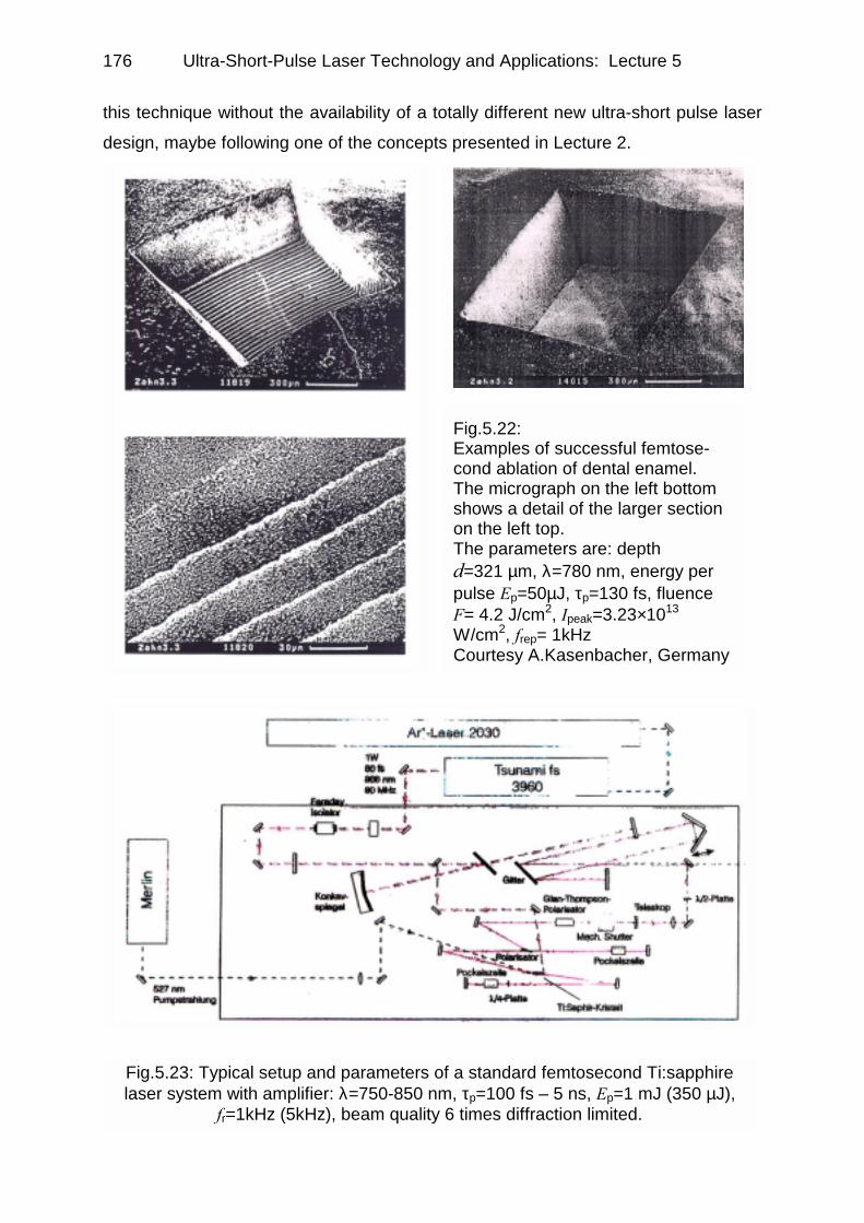
As a conclusion of this subsection, 3 electron micrographs (Fig.5.22a,b,c) are pre-
sented showing examples of successful dental enamel processing by femtose-cond pulses (A. Kasenbacher in cooperation with Laser-Zentrum Hannover). These
results have been acquired with a commercial laser system of rather great complexity
comparable to the setup depicted in Fig.5.23 not allowing commercial application of
Ultra-Short-Pulse Laser Technology and Applications: Lecture 5 176
Fig.5.22: Examples of successful femtose-cond ablation of dental enamel. The micrograph on the left bottom shows a detail of the larger section on the left top. The parameters are: depth d=321 µm, λ=780 nm, energy per pulse Ep=50µJ, τp=130 fs, fluence F= 4.2 J/cm2, Ipeak=3.23×10¹³ W/cm2, frep= 1kHz Courtesy A.Kasenbacher, Germany
this technique without the availability of a totally different new ultra-short pulse laser
design, maybe following one of the concepts presented in Lecture 2.
Fig.5.23: Typical setup and parameters of a standard femtosecond Ti:sapphire laser system with amplifier: λ=750-850 nm, τp=100 fs – 5 ns, Ep=1 mJ (350 µJ),
fr=1kHz (5kHz), beam quality 6 times diffraction limited.

Ultra-Short-Pulse Laser Technology and Applications: Lecture 5
177
Fig.5.24: Optical photomicrograph showinga 550 µm deep excision in bovine brain tis-sue. τp=140 fs, Ep=11 µJ, λ=800 nm, spot size dspot=20 µm, excision volume by abla-tion Va=0.37 mm3, number of applied pul-ses N=36000. Va/pulse=10.3×103 µm3. Thesample was stained with HE.
Fig.5.25: Corneal ultra-ac-curate surgery by femtosecond laser pulses: (top row) SEMs of in-vitro intrastromal cutt-ing in primate eye, (a) successful by femtosecond and (b) unsatisfactory by 60ps pulses. (bottom row) Intraoperative and 1-week post-oper-ative view of rab-bit eye treated with femtosecond laser pulses in a spiral pattern.
5.4.2 Applications to soft-tissue ablation: examples
Soft-tissue can be ablated by ultra-
short pulses very effectively, as the
example on bovine brain tissue given
in Fig.5.24 [26] shows. The precision of the cut and the complete absence of thermal collateral damage are in-
triguing. The laser operation data are
mentioned in the figure caption.
Also applications in ophthalmology
have been successfully tested. Corne-
al shaping usually is well-known in the
context of application of excimer laser
radiation. Fig.5.25 depicts a series of 4
scanning electron micrographs of in-vitro intrastromal cutting in a primate eye
(i.e. a cut achieved in the interior of the cornea by a two-dimensional series of optical
breakdowns) [27]. The first row allows a comparison between (a, left) a successfully
Ultra-Short-Pulse Laser Technology and Applications: Lecture 5 178
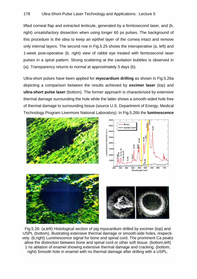
Fig.5.26: (a,left) Histological section of pig myocardium drilled by excimer (top) and USPL (bottom), illustrating extensive thermal damage or smooth-side holes, respecti-vely. (b,right) Luminescence signal for bone and spinal cord. The prominent Ca peaks
allow the distinction between bone and spinal cord or other soft tissue. (bottom,left) 1 ns ablation of enamel showing extensive thermal damage and cracking. (bottom,
right) Smooth hole in enamel with no thermal damage after drilling with a USPL.
lifted corneal flap and extracted lenticule, generated by a femtosecond laser, and (b,
right) unsatisfactory dissection when using longer 60 ps pulses. The background of
this procedure is the idea to keep an epithel layer of the cornea intact and remove
only internal layers. The second row in Fig.5.25 shows the interoperative (a, left) and
1-week post-operative (b, right) view of rabbit eye treated with femtosecond laser
pulses in a spiral pattern. Strong scattering at the cavitation bubbles is observed in
(a). Transparency returns to normal at approximately 3 days (b).
Ultra-short pulses have been applied for myocardium drilling as shown in Fig.5.26a
depicting a comparison between the results achieved by excimer laser (top) and
ultra-short pulse laser (bottom). The former approach is characterized by extensive
thermal damage surrounding the hole while the latter shows a smooth-sided hole free
of thermal damage to surrounding tissue (source U.S. Department of Energy, Medical
Technology Program Livermore National Laboratory). In Fig.5.26b the luminescence

Ultra-Short-Pulse Laser Technology and Applications: Lecture 5
179
Fig.5.27: Optical coherence tomographyfilling headlines of journals: tomogram ofXenopus laevis (African frog) with sub-cellular resolution.
signals of different tissue sections are identified by their spectroscopic lines. This
idea also has a great potential for identification feedback when ablating dental tissue.
5.4.3 Optical coherence tomography using ultra-short pulses
A very challenging rather new field of application of shortest femtosecond pulses is
optical coherence tomography [28] which was advertised in recent years in many pub-
lications, e.g. in the trade journal Biophotonics (October 1999) on the front page
(Fig.5.27). This method originally involved superluminescent diodes having a rather
short coherence length defining the resolution of measurement [29], originally of dist-
ances between optically different lay-
ers in the eye, like the thickness of
the cornea or the depth of the eye
down to the retina [30]. Soon, two-di-
mensional scanning of the back-
ground of the eye was achieved and,
furthermore, this method was applied
to a variety of scattering biological
media like skin tissue or dental tissue
[31]. A major step forward was made
by taking advantage of the short coherence length of femtosecond
pulses which is in the µm regime
and hence about one order of magni-
tude shorter than the one of superlu-
minescent diodes but associated with
excellent brightness of laser sources.
As a definition, optical coherence to-
mography allows non-invasive images of cross-sections (tomograms) in scattering
media, especially in biological tissue. Imaging through scattering media was an issue
since long time, i.e. since the early das of laser development. Fig.5.28 schematically
shows the propagation of a laser pulse through scattering media. The unscattered
photons are faster, but fewer and under normal conditions completely overwhelmed
by the scattered photons arriving later. If it is possible to establish a temporal gate

Ultra-Short-Pulse Laser Technology and Applications: Lecture 5 180
Fig.5.28: Scheme for imaging through scattering media (a) by employing a fast optical gate switch allowing just few unscattered but faster photons to reach the detection system generat-ing the image while the larger numbers of scattered photons are shut off (b).
Fig.5.29: (upper half) Scheme of a fiber-optic Michelson interferometer for optical coherence tomography consisting of measurement (S) and reference (R) arms. (lower half) Tomographic cross sections through an onion, taken (a) by high-resolution Ti:S OCT or (b) superluminescence diode OCTsystems [32].
switch to select only the unscattered photons, imaging becomes possible. This was
achieved by non-linear fast optical switches which, however, are very inefficient and
require large laser power. In the concept of OCT, the gate is realized as a coher-ence gate.
Fig.5.29 exhibits a very simplified scheme of a modern fiber-based optical coher-ence tomograph [32]. It
seems to be worth mentio-
ning that it is no problem or
even contradiction when
considering ∼ 10 fs pulses
with a bandwidth of about
120 nm propagating through
non-negligible lengths of
optical fiber associated with
a lot of dispersion. It is the

Ultra-Short-Pulse Laser Technology and Applications: Lecture 5
181
Fig.5.30: Comparison of bandwidth (top) and coherence length (bottom) for super-
luminescent diodes and femtosecond laser pulses
coherence length and bandwidth remaining unchanged even if the originally band-
width limited pulses out of the laser are torn apart by dispersion. A compensator
within the reference arm should provide approximately equal dispersion conditions in
both, the measurement and the reference arm. Fig.5.30 allows a comparison of
bandwidth and coherence length for superluminescent diodes and femtosecond laser
pulses being more or less self-explaining. Thus, superluminescence diodes yield
∼ 20 µm longitudinal resolution while femtosecond lasers achieve one order of
magnitude smaller values, i.e. ≥2 µm.
In this way, a resolution of ∼ 2 µm in the
longitudinal direction is achieved as it
can be seen in Fig.5.31 showing sub-cellular details of African frog tissue
(xenopus laevis [33,34]) with a lateral re-
solution of 3 µm. This most modern
version of OCT, although so far only
performed by Ti:sapphire pulses
around 800 nm penetrating about 1
mm into normal tissue, seems to be
ideally suited for the application of
diode-pumped femtosecond lasers like
Cr3+:LiSAF or LiSGaF as they can be
directly diode-pumped and hence are
substantially simpler and potentially
cheaper. Their penetration depth is
also somewhat deeper due to the
center wavelength being about 100 nm
longer. The average power needed for OCT lies in the sub-10mW regime, usually it
is 3-5 mW, representing a rather modest requirement in general. For ophtalmological
applications only 300 µW are needed and only ∼ 1mW would be permissible for safety
reasons [35]. The implementation of OCT together with compact and moderately priced femtosecond laser sources in several wavelength regimes would be highly
desirable: there are absorption windows around 950 nm, 1300 nm (yielding approxi-
mately 4 mm penetration depth) and 2200 nm. If taking also advantage of secondary

Ultra-Short-Pulse Laser Technology and Applications: Lecture 5 182
Fig.5.31: Optical coherence tomograms of African frog tadpole (Xenopus laevis) yielded by a Ti:sapphire femtosecond laser having τp=5.4 fs and 250 nm band-width revealing sub-cellular resolution. The image is 0.83 × 1 mm large, 1800 ×
1000 pixels. On the left picture, the olefactory tube (OT) and mitosis of 2 cell pairs(arrows) are shown. Courtesy of W. Drexler.
information like spatially resolved dispersion and absorption (compare Fig.5.32
[36]) this will revolutionize in-vivo non-destructive medical diagnosis being applicable
to many areas of interest via endoscopic methods.
Optical coherence tomography is al-
so, as mentioned above, used for
dental applications: Fig.5.33 illu-
strates this approach and its results
in an impressive way allowing to di-
stinguish the various features of a
tooth, aiding diagnosis (source U.S
Department of Energy, UCRL-MI-
129402).
Fig.5.32: Comparison of high-resolution (top) and spectroscopic (bottom) femtose-cond OCT. By exploiting linear optical properties like dispersion and absorption, ad-ditional contrast can be yielded which usually is depicted in false colors as the bar
below the pictures indicates [36].

Ultra-Short-Pulse Laser Technology and Applications: Lecture 5
183
Fig.5.33: Optical coherence tomography for dental applications. (left) Cross secti-onal images taken with OCT can be combined to give a 3-dimensional represen-tation. (right) In the OCT image (right part) the various features of a tooth can be
easily distinguished, aiding diagnosis.
Fig.5.34: Example of multi-photon non-linear microscopy depicting two-photon fluorescence of leukaemia cells of rats [37]
5.4.4 Three-dimensional resolution by non-linear interactions within the focus of ultra-short pulses
Ultra-short pulses having sufficient sin-
gle pulse energy and repetition rates in
the MHz regime allow the application of
high peak powers to the focal spots
reaching intensities as required for var-ious non-linear processes without
destroying the sample necessarily, to-
gether with sufficient speed for e.g.
sampling or scanning purposes. Multi-photon non-linear microscopy (e.g.
[37]) takes advantage of this aspect al-
lowing three-dimensional resolution
via two- and three-photon fluorescence
excitation or second and third harmonic
generation. In this case, the require-
ments with respect to short pulse dur-
ation or high-average power are not
very stringent. Therefore, this techni-
que has been started to be employed

Ultra-Short-Pulse Laser Technology and Applications: Lecture 5 184
Fig.5.35: Classical steps of rapid-prototyping employing monomers to become UV-hardened: first a cal-culated CAD-model is computer-decomposed into layers. In each of the layers laser-assisted gen-eration of cured rasin structures is carried out, which consecutively form the real 3D model. The fabrication of the single solidified layers involves a number of mechanical steps of motion like dip-ping in and wiping off, so that the overall process is rather time consuming.
already a number of years ago. Fig.5.34 represents a very successful example de-
picting two-photon fluorescence of leukaemia cells of rats [37]. The development of
compact diode-pumped sources might contribute to the wide spread of this technique
in an innovative way as well as the availability of a wide spectral range of ultra-short
pulses.
Related to this concept, with respect to localized non-linear intra-focal interaction,
but demanding for much more average power is a rather novel approach to rapid-prototyping with polymers. Traditionally, two-dimensional computer controlled expo-
sition of monomers to UV cw laser radiation allows to solidify them to polymeric struc-
tures. They have to be created layer by layer eventually yielding a sizable three-di-mensional body. Typical commercial exposition times for 30 cm sized figures are of
the order of 50 hours limited by UV laser power on the one hand, but also by many
mechanical steps like immersion into the liquid monomer, wiping off the excess liquid,
linear sequential exposition by a scanned focus and so forth. Fig.5.35 illustrates how
this technique works. 3D-prototyping, however, makes use of three-dimensional
confinement of non-linear interactions within the focus of an ultra-short pulse train.
Two- or three-photon absorption can expose a monomer [38,39] and create a hard
structure within the volume of the liquid [40] starting from a substrate. There are no
mechanical motions required any more, and therefore the process is potentially much
Ultra-Short-Pulse Laser Technology and Applications: Lecture 5
185
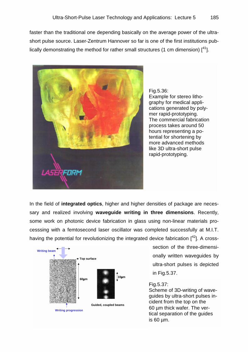
Fig.5.36: Example for stereo litho-graphy for medical appli-cations generated by poly-mer rapid-prototyping. The commercial fabrication process takes around 50 hours representing a po-tential for shortening by more advanced methods like 3D ultra-short pulse rapid-prototyping.
Writing progression
Top surface
60µµµµm 10µµµµm
Writing beam
Guided, coupled beams
faster than the traditional one depending basically on the average power of the ultra-
short pulse source. Laser-Zentrum Hannover so far is one of the first institutions pub-
lically demonstrating the method for rather small structures (1 cm dimension) [41].
In the field of integrated optics, higher and higher densities of package are neces-
sary and realized involving waveguide writing in three dimensions. Recently,
some work on photonic device fabrication in glass using non-linear materials pro-
cesssing with a femtosecond laser oscillator was completed successfully at M.I.T.
having the potential for revolutionizing the integrated device fabrication [42]. A cross-
section of the three-dimensi-
onally written waveguides by
ultra-short pulses is depicted
in Fig.5.37.
Fig.5.37: Scheme of 3D-writing of wave-guides by ultra-short pulses in-cident from the top on the 60 µm thick wafer. The ver- tical separation of the guides is 60 µm.

Ultra-Short-Pulse Laser Technology and Applications: Lecture 5 186
time
27.2 ns 24 ns
time
Power
271-bitword
time
λλλλ 27.2 ns
fs FiberLaser
36.7 MHz
4 km DCF (-340ps/nm)
9.94 Gb/s Data
Pulse PatternGenerator
InGaAsPModulator
Ext.Clock
271RF
harm.
st
9.94 GHz
TDM
λλλλ
<100 fs
101 10 ... 11" " " "11 0271-bitword
21 ns27.2 ns
Tx Output
(*) Dynamic biasadjustment
Fig.5.38: Schematic diagram of 206-channel chirped-pulse WDM transmitter by Boivin et al. [43]. The channels are spaced by ∼ 37 GHz, the channel bit rate is
36.7 Mbit/s and the aggregate bit rate is 9.942 Gbit/s. The device is operated by a single mode-locked femtosecond fiber laser and a single TDM modulator
5.4.5 Advanced applications in optical communications
Also in the field of optical communication femtosecond pulses become more and
more important and get used for wavelength division multiplexing (WDM) and
demultiplexing. Fig.5.38 illustrates a 206-channel chirped-pulse WDM transmitter as
published by Nuss, Knox and collaborators at Bell Laboratories about 4 years ago
[43]. This represented a record for the number of channels, using a single femtose-
cond laser (τp < 100 fs, fr =36.7 MHz @1.55 µm) and a single time-division multiplex-
ed electro-absorption modulator. The channel spacing is ∼ 37 GHz (0.3 nm), and the
bit rate in each channel is 36.7 Mbit/s. In the meantime, this approach has been dra-
matically improved to a 1021 channel WDM system [44]. Very recently, 80 Gbit/s de-
multiplexing via a semiconductor optical amplifier in an ultra-fast nonlinear interfero-
meter using two mode-locked fiber lasers (@ 1550 nm and 1545 nm) yielding a 5 ps
switching window has been achieved at M.I.T. Lincoln Laboratory [45].

Ultra-Short-Pulse Laser Technology and Applications: Lecture 5
187
References (Lecture 5): [1] E. Wintner, J. Appl.Phys. 57, 1533 (1985) [2] E. Wintner, Optics and Laser Technology 17, 159 (1985) [3] E. Wintner and E.P. Ippen, Appl. Phys. Lett. 44, 999 (1984) [4] R.A. Höpfel, N. Sawaki, E. Wintner, Appl. Phys. Lett. 55, 460 (1989) [5] Ch. Spielmann, R. Szipöcs, A. Stingl, F. Krausz, Phys. Rev. Lett. 73, 2308 (1994) [6] D. Scifres, Conf. on Lasers and Electro-Optics, CLEO (1999) [7] C. Momma et al., Laser und Optoelektronik 29, 82 (1997) [8] M.R.H. Knowles, G. Rutterford, A.I. Bell, A.J. Andrews, G. Foster-Turner, A.J. Kearsley,
D.W. Coutts, D. Kapitan, C.E. Webb, CLEO 2000 San Francisco, paperCFD5, p 581 [9] M. Lenzner, J. Krüger, S. Sartania, Z.Cheng, Ch. Spielmann, G. Mourou, W. Kautek, F.Krausz,
Phys. Rev. Lett. 80, 4076 (1998) [10] N. Bloembergen, IEEE J. Quantum Electron. QE-10, 375 (1974) [11] R.M. Wood, Laser Damage in Optical Materials (Hilger, Boston, 1986) [12] S.C. Jones et al., Opt. Eng. 28, 1039 (1989) [13] M.H. Niemz, Appl. Phys. Lett. 66, 1181 (1995) [14] B.C. Stuart et al., Phys. Rev. Lett. 74, 2248 (1995) ; J. Opt. Soc. Am. B 13, 459 (1996) [15] L. Zack, G. Cohen, Pulp response on external applied heat, OS,OM & OP V 19, 515-430 (1965) [16] A. Mehl, L. Kremers, K. Salzmann, R. Hickel, 3D-volume-ablation rate and thermal side effects with
the Er:YAG and Nd:YAG laser, Dent. Mater. 13, 246-251 (1997) [17] G.B. Altshuler, N.R. Belashenkov, V.B. Karasev, A.V. Skripnik, A.A. Solunin, Application of ultra-
short laser pulses in dentistry, SPIE 2080, 77-81 (1993) [18] A. Mindermann, M.H. Niemz, L. Eisenmann, F.H. Loesel, J.F. Bille, Comparison of three different
laser systems for application in dentistry, SPIE 2080 Dental Application of Lasers, 68-76 (1993) [19] M.H. Niemz, Schmerzfreie Zahnpräparation mit dem Nd:YLF-Pikosekundenlase, Laser und
Optoelektronik 26, 68-73 (1994) [20] A.M. Rubenchik, L.B. Da Silva, M.D. Feit, S. Lane, R. London, M.D. Perry, B.C. Stuart, J. Neev,
Dental Tissue Processing with Ultra-Short Pulse Laser, SPIE 2672, 222-230 (1996) [21] W. Seka, J.D.B. Featherstone, D. Fried, S.R. Visuri, J.T. Wals, Laser ablation of dental hard tissue:
from explosive ablation to plasma-mediated ablation, SPIE 2672, 144-158 (1996) [22] M.D. Perry et al., Ultra-short pulse laser machining of dielectric materials, J. Appl. Phys. 65,
(1999) [23] M.D. Feit, A.M. Rubenchik, B.W. Shore, Unique Aspects of Laser Energy Deposition in the fs Pulse
Regime, SPIE 2672, 243-249 (1996) [24] A.A. Oraevsky, L.B. da Silva, A.M. Rubenchik, M.D. Feit, M.E. Glinsky, M.D. Perry, B.M. Mammini,
W. Small, B.C. Stuart, Plasma Mediated Ablation of Biological Tissues with Nanosecond- to Femtosecond Laser Pulses: Relative Role of Linear and Nonlinear Absorption, IEEE J. Sel. Top. Quantum Electron. 2, 801-809 (1996)
[25] J. Neev, D.S. Huynh, C.C. Dan, J.M. White, L.B. da Silva, M.D. Feit, D.L. Matthews, M.D. Perry, A.M. Rubenchik, B.C. Stuart, Scanning Electron Microscopy and Ablation Rates of Hard Dental Tissue Using 350 fs and 1 ns Laser Pulses, SPIE 2672, 250-261 (1996)
[26] F.H. Loesel et al., Non-thermal ablation of neural tissue with femtosecond laser pulses, Appl. Phys. B 66, 121 (1998)
[27] T. Juhasz, F.H. Loesel, C. Horvath, R.M. Kurtz, G. Mourou, invited talk, Digest Ultrafast Phenomena, Garmisch Partenkirchen (1998)
[28] Ultrafast Phenomena XII-OSA Technical Digest (Optical Society of America, Washington DC (2000); Ultrafast Phenomena X-Proceedings of the 10th International Conference, Del Coronado, CA (1996) (Springer Series in Chemical Physics 62); Ultrafast Phenomena XI-Proceedings of the 11th International Conference, Garmisch-Partenkirchen (1998) (Springer Series in Chemical Physics 63).
[29] For a comprehensive review: A.F. Fercher, J. Biomed. Opt. 1, 157 (1996) [30] W. Drexler, In vivo optical coherence tomography and topography of the fundus of the human eye,
PhD thesis, Univ. Technology Vienna (1995) [31] A. Baumgartner, Ch.K. Hitzenberger, S. Dichtl, H. Sattmann, A. Moritz, W. Sperr, A.F. Fercher,
Proc. SPIE 3248, 130 (1998) [32] W. Drexler, U. Morgner, F.X. Kärntner, C. Pitris, S.A. Boppart, X.D. Li, E.P. Ippen, J.G. Fujimoto,
Opt. Lett. 24, 1221 (1999) [33] W. Drexler, private communication (2000)

Ultra-Short-Pulse Laser Technology and Applications: Lecture 5 188
[34] U. Morgner, F.X. Kärntner, S.H. Cho, Y. Chen, H.A. Haus, J.G. Fujimoto, E.P. Ippen, V. Scheuer,
G. Angelow, T. Tschudi, Opt. Lett. 24, 411 (1999) [35] comp. European Standard EN 60825-1 about safety of laser products (1996); based on IEC 825-
1:1993+A11:1996 [36] U. Morgner, W. Drexler, F.X. Kärtner, X.D. Li, C. Pitris, E.P. Ippen, J.G. Fujimoto, Opt. Lett. 25,
111(2000) [37]. Ch. Xu, W. Zipfel, J. Shear, R. Williams, W. Webb, Proc. Natl. Acad. Sci. USA 93, 10763 (1996) [38]. Ch. Ondrusek, diploma thesis, Univ. Technology Vienna (2001) [39]. B.H. Cumpston, S.P. Ananthavel, S. Barlow, D.L. Dyer, J.E. Ehrlich, L.L. Erskine, A.A. Heikal,
S.M. Kuebler, I.-Y. Sandy Lee, D. McCord-Maughon, J Qin, H. Röckel, M. Rumi, Xiang-Li Wu, S.R. Marder, J.W.Perry, Nature 398, 51 (1999)
[40]. S. Kawata, Hong-Bo Sun, T. Tanaka, K. Takada, Nature 412, 697 (2001) [41]. B.N. Chichkov, private communication; announcement at LASER 2001 World of Photonics,
Munich 2001 [42]. K. Minoshima, A.M. Kovalevicz, I. Hartl, E.P. Ippen and J.G. Fujimoto, Opt. Lett. (in press, 2001) [43]. L. Boivin, M.C. Nuss, W.H. Knox, J.B. Stark, Electron. Lett. 33, 827 (1997) [44]. B.C. Collings, M.L. Mitchell, L. Boivin, W.H. Knox, IEEE Photon. Tech. Lett. 12, 906 (2000) [45]. E.P. Ippen, private communication 2001