Embed Size (px)
Citation preview
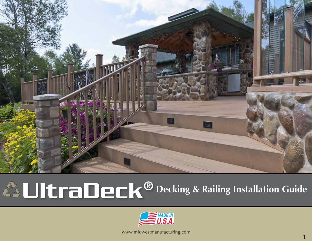
Decking & Railing Installation Guide
www.midwestmanufacturing.com
UltraDeck®
1
1
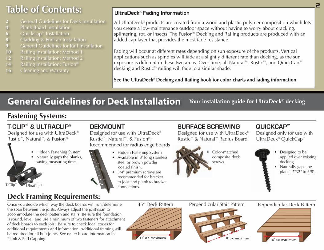
Table of Contents:2 General Guidelines for Deck Installation4 Plank Board Installation6 QuickCap™ Installation8 Cladding & Endcap Installation9 General Guidelines for Rail Installation10 Railing Installation: Method 112 Railing Installation: Method 214 Railing Installation: Fusion®
16 Cleaning and Warranty
General Guidelines for Deck Installation
• Hidden Fastening System• Available in 8' long stainless
steel or brown powder coated finish.• 3/4" premium screws are
recommended for bracket to joist and plank to bracket connections.
• Hidden Fastening System • Naturally gaps the planks,
saving measuring time.
• Color-matched composite deck screws.
• Designed to be applied over existing decking
• Naturally gaps the planks 7/32" to 3/8".
DEKMOUNTDesigned for use with UltraDeck®
Rustic™, Natural™, & Fusion®; Recommended for radius edge boards
T-CLIP™ & ULTRACLIP®
Designed for use with UltraDeck®
Rustic™, Natural™, & Fusion®
SURFACE SCREWINGDesigned for use with UltraDeck®
Rustic™ & Natural™ Radius Board
QUICKCAP™
Designed only for use with UltraDeck® QuickCap™
Fastening Systems:
Once you decide which way the deck boards will run, determine the span between the joists. Always adjust the joist span to accommodate the deck pattern and stairs. Be sure the foundation is sound, level, and use a minimum of two fasteners for attachment of deck boards to each joist. Be sure to check local codes for additional requirements and information. Additional framing will be required for all butt joints. See nailer board information in Plank & End Gapping. 12" o.c. maximum
45° Deck Pattern
8" o.c. maximum
Perpendicular Stair Pattern
16" o.c. maximum
Perpendicular Deck Pattern
Deck Framing Requirements:
Your installation guide for UltraDeck® decking
T-Clip™ UltraClip®
UltraDeck® Fading Information
All UltraDeck® products are created from a wood and plastic polymer composition which lets you create a low-maintenance outdoor space without having to worry about cracking, splintering, rot, or insects. The Fusion® Decking and Railing products are produced with an added cap layer that provides the most fade resistance.
Fading will occur at different rates depending on sun exposure of the products. Vertical applications such as spindles will fade at a slightly different rate than decking, as the sun exposure is different in these two areas. Over time, all Natural™, Rustic™, and QuickCap™ decking and Rustic™ railing will fade to a similar shade.
See the UltraDeck® Decking and Railing book for color charts and fading information.
2
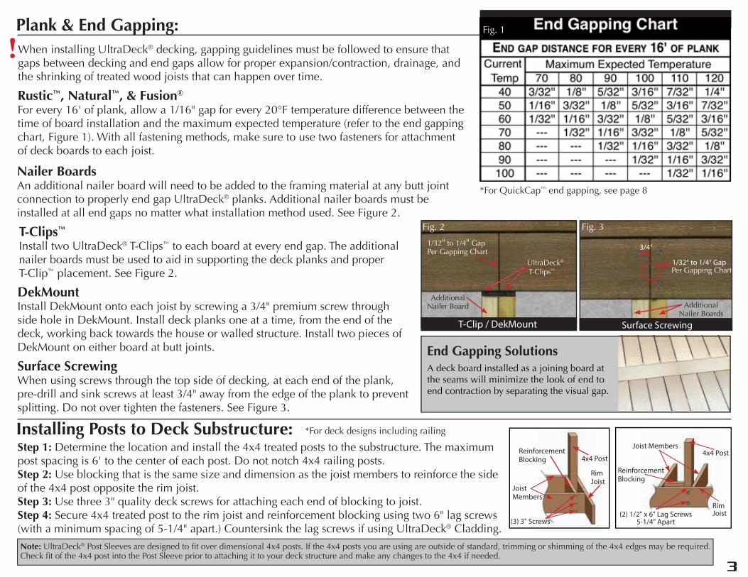
When installing UltraDeck® decking, gapping guidelines must be followed to ensure that gaps between decking and end gaps allow for proper expansion/contraction, drainage, and the shrinking of treated wood joists that can happen over time.
3/4"
1/32" to 1/4" GapPer Gapping Chart
Surface Screwing
Nailer BoardsAn additional nailer board will need to be added to the framing material at any butt joint connection to properly end gap UltraDeck® planks. Additional nailer boards must be installed at all end gaps no matter what installation method used. See Figure 2.
Plank & End Gapping:
!
T-Clips™
Install two UltraDeck® T-Clips™ to each board at every end gap. The additional nailer boards must be used to aid in supporting the deck planks and proper T-Clip™ placement. See Figure 2.
Rustic™, Natural™, & Fusion®
For every 16' of plank, allow a 1/16" gap for every 20°F temperature difference between the time of board installation and the maximum expected temperature (refer to the end gapping chart, Figure 1). With all fastening methods, make sure to use two fasteners for attachment of deck boards to each joist.
DekMountInstall DekMount onto each joist by screwing a 3/4" premium screw through side hole in DekMount. Install deck planks one at a time, from the end of the deck, working back towards the house or walled structure. Install two pieces of DekMount on either board at butt joints.
Surface ScrewingWhen using screws through the top side of decking, at each end of the plank, pre-drill and sink screws at least 3/4" away from the edge of the plank to prevent splitting. Do not over tighten the fasteners. See Figure 3.
Note: UltraDeck® Post Sleeves are designed to fit over dimensional 4x4 posts. If the 4x4 posts you are using are outside of standard, trimming or shimming of the 4x4 edges may be required. Check fit of the 4x4 post into the Post Sleeve prior to attaching it to your deck structure and make any changes to the 4x4 if needed.
4x4 PostJoist Members
Reinforcement Blocking
Rim Joist(2) 1/2" x 6" Lag Screws
5-1/4" Apart
A deck board installed as a joining board at the seams will minimize the look of end to end contraction by separating the visual gap.
End Gapping Solutions
4x4 Post
Rim Joist
Joist Members
Reinforcement Blocking
(3) 3" Screws
Installing Posts to Deck Substructure:Step 1: Determine the location and install the 4x4 treated posts to the substructure. The maximum post spacing is 6' to the center of each post. Do not notch 4x4 railing posts.Step 2: Use blocking that is the same size and dimension as the joist members to reinforce the side of the 4x4 post opposite the rim joist. Step 3: Use three 3" quality deck screws for attaching each end of blocking to joist.Step 4: Secure 4x4 treated post to the rim joist and reinforcement blocking using two 6" lag screws (with a minimum spacing of 5-1/4" apart.) Countersink the lag screws if using UltraDeck® Cladding.
*For deck designs including railing
Fig. 1
Fig. 3Fig. 2
Additional Nailer Boards
Additional Nailer Board
UltraDeck®
T-Clips™
1/32" to 1/4" Gap Per Gapping Chart
T-Clip / DekMount
Fig. 2
*For QuickCap™ end gapping, see page 8
3
2
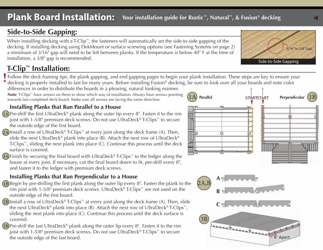
When installing decking with a T-Clip™, the fasteners will automatically set the side-to-side gapping of the decking. If installing decking using DekMount or surface screwing options (see Fastening Systems on page 2) a minimum of 3/16" gap will need to be left between planks. If the temperature is below 40˚ F at the time of installation, a 3/8" gap is recommended.
3/16" to 3/8" Gap
Side-to-Side Gapping
Plank Board Installation: Your installation guide for Rustic™, Natural™, & Fusion® decking
Side-to-Side Gapping:
Follow the deck framing tips, the plank gapping, and end gapping pages to begin your plank installation. These steps are key to ensure your decking is properly installed to last for many years. Before installing Fusion® decking, be sure to look over all your boards and note color differences in order to distribute the boards in a pleasing, natural looking manner.
Installing Planks that Run Parallel to a HousePre-drill the first UltraDeck® plank along the outer lip every 8". Fasten it to the rim joist with 1-5/8" premium deck screws. Do not use UltraDeck® T-Clips™ to secure the outside edge of the first board. Install a row of UltraDeck® T-Clips™ at every joist along the deck frame (A). Then, slide the next UltraDeck® plank into place (B). Attach the next row of UltraDeck® T-Clips™, sliding the next plank into place (C). Continue this process until the deck surface is covered. Finish by securing the final board with UltraDeck® T-Clips™ to the ledger along the house at every joist. If necessary, cut the final board down to fit, pre-drill every 8", and fasten it to the ledger with premium deck screws.
Installing Planks that Run Perpendicular to a HouseBegin by pre-drilling the first plank along the outer lip every 8". Fasten the plank to the rim joist with 1-5/8" premium deck screws. UltraDeck® T-Clips™ are not used on the outside edge of the first board. Install a row of UltraDeck® T-Clips™ at every joist along the deck frame (A). Then, slide the next UltraDeck® plank into place (B). Attach the next row of UltraDeck® T-Clips™, sliding the next plank into place (C). Continue this process until the deck surface is covered. Pre-drill the last UltraDeck® plank along the outer lip every 8". Fasten it to the rim joist with 1-5/8" premium deck screws. Do not use UltraDeck® T-Clips™ to secure the outside edge of the last board.
T-Clip™ Installation:
!
8" Apart
START
A B
C
Parallel Perpendicular1A
2A,B
3B
Note: T-Clips™ have arrows on them to show which way of installation. Always have arrows pointing towards last completed deck board. Make sure all arrows are facing the same direction.
1A
2A
3A
1BSTARTSTART
1B
2B
3B
4
Follow the deck framing tips, the plank gapping, and end gapping pages to begin your plank installation. These steps are key to ensure your decking is properly installed to last for many years. Before installing Fusion® decking, be sure to look over all your boards and note color differences in order to distribute the boards in a pleasing, natural looking manner.
Follow the deck framing tips, the plank gapping, and end gapping pages to begin your plank installation. These steps are key to ensure your decking is properly installed to last for many years.
!
!
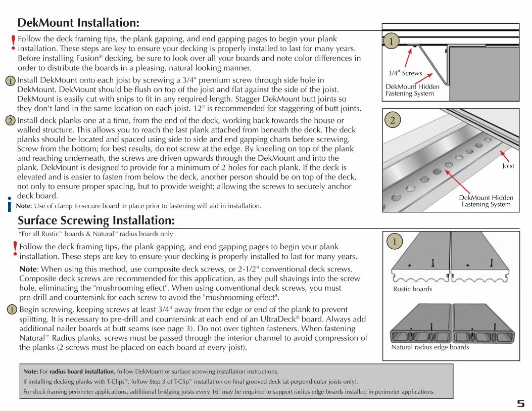
DekMount Installation:
Surface Screwing Installation:
Note: When using this method, use composite deck screws, or 2-1/2" conventional deck screws. Composite deck screws are recommended for this application, as they pull shavings into the screw hole, eliminating the "mushrooming effect". When using conventional deck screws, you must pre-drill and countersink for each screw to avoid the "mushrooming effect".
Begin screwing, keeping screws at least 3/4" away from the edge or end of the plank to prevent splitting. It is necessary to pre-drill and countersink at each end of an UltraDeck® board. Always add additional nailer boards at butt seams (see page 3). Do not over tighten fasteners. When fastening Natural™ Radius planks, screws must be passed through the interior channel to avoid compression of the planks (2 screws must be placed on each board at every joist).
Install DekMount onto each joist by screwing a 3/4" premium screw through side hole in DekMount. DekMount should be flush on top of the joist and flat against the side of the joist. DekMount is easily cut with snips to fit in any required length. Stagger DekMount butt joints so they don't land in the same location on each joist. 12" is recommended for staggering of butt joints.
Install deck planks one at a time, from the end of the deck, working back towards the house or walled structure. This allows you to reach the last plank attached from beneath the deck. The deck planks should be located and spaced using side to side and end gapping charts before screwing. Screw from the bottom; for best results, do not screw at the edge. By kneeling on top of the plank and reaching underneath, the screws are driven upwards through the DekMount and into the plank. DekMount is designed to provide for a minimum of 2 holes for each plank. If the deck is elevated and is easier to fasten from below the deck, another person should be on top of the deck, not only to ensure proper spacing, but to provide weight; allowing the screws to securely anchor deck board.
1
2
3/4" Screws
DekMount Hidden Fastening System
DekMount Hidden Fastening System
Joist
1
1
*For all Rustic™ boards & Natural™ radius boards only1
2
Note: Use of clamp to secure board in place prior to fastening will aid in installation.i
Rustic boards
Natural radius edge boards
Note: For radius board installation, follow DekMount or surface screwing installation instructions.
If installing decking planks with T-Clips™, follow Step 3 of T-Clip™ installation on final grooved deck (at perpendicular joists only).
For deck framing perimeter applications, additional bridging joists every 16" may be required to support radius edge boards installed in perimeter applications.
4
5
QuickCap™ Installation: Your installation guide for QuickCap™ decking
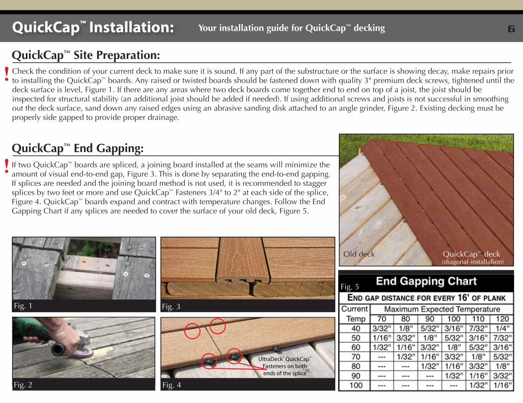
If two QuickCap™ boards are spliced, a joining board installed at the seams will minimize the amount of visual end-to-end gap, Figure 3. This is done by separating the end-to-end gapping. If splices are needed and the joining board method is not used, it is recommended to stagger splices by two feet or more and use QuickCap™ Fasteners 3/4" to 2" at each side of the splice, Figure 4. QuickCap™ boards expand and contract with temperature changes. Follow the End Gapping Chart if any splices are needed to cover the surface of your old deck, Figure 5.
!QuickCap™ End Gapping:
QuickCap™ Site Preparation:Check the condition of your current deck to make sure it is sound. If any part of the substructure or the surface is showing decay, make repairs prior to installing the QuickCap™ boards. Any raised or twisted boards should be fastened down with quality 3" premium deck screws, tightened until the deck surface is level, Figure 1. If there are any areas where two deck boards come together end to end on top of a joist, the joist should be inspected for structural stability (an additional joist should be added if needed). If using additional screws and joists is not successful in smoothing out the deck surface, sand down any raised edges using an abrasive sanding disk attached to an angle grinder, Figure 2. Existing decking must be properly side gapped to provide proper drainage.
!
Fig. 2
Old deck QuickCap™ deck (diagonal installation)
Fig. 1 Fig. 3
Fig. 5
UltraDeck® QuickCap™ Fasteners on both ends of the splice
Fig. 4
6
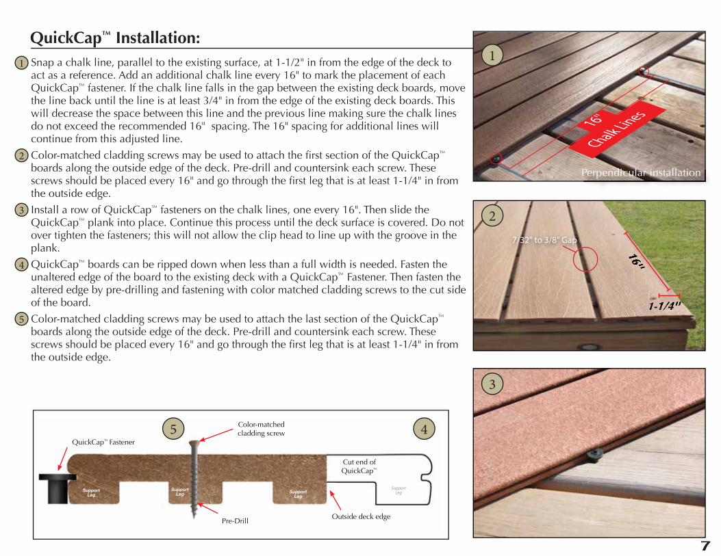
QuickCap™ Installation:Snap a chalk line, parallel to the existing surface, at 1-1/2" in from the edge of the deck to act as a reference. Add an additional chalk line every 16" to mark the placement of each QuickCap™ fastener. If the chalk line falls in the gap between the existing deck boards, move the line back until the line is at least 3/4" in from the edge of the existing deck boards. This will decrease the space between this line and the previous line making sure the chalk lines do not exceed the recommended 16" spacing. The 16" spacing for additional lines will continue from this adjusted line.
Color-matched cladding screws may be used to attach the first section of the QuickCap™ boards along the outside edge of the deck. Pre-drill and countersink each screw. These screws should be placed every 16" and go through the first leg that is at least 1-1/4" in from the outside edge.
Install a row of QuickCap™ fasteners on the chalk lines, one every 16". Then slide the QuickCap™ plank into place. Continue this process until the deck surface is covered. Do not over tighten the fasteners; this will not allow the clip head to line up with the groove in the plank.
QuickCap™ boards can be ripped down when less than a full width is needed. Fasten the unaltered edge of the board to the existing deck with a QuickCap™ Fastener. Then fasten the altered edge by pre-drilling and fastening with color matched cladding screws to the cut side of the board.
Color-matched cladding screws may be used to attach the last section of the QuickCap™ boards along the outside edge of the deck. Pre-drill and countersink each screw. These screws should be placed every 16" and go through the first leg that is at least 1-1/4" in from the outside edge.
Cut end ofQuickCap™
Color-matchedcladding screw
QuickCap™ Fastener
SupportLeg
SupportLeg Support
Leg
SupportLeg
Outside deck edgePre-Drill
16''
1-1/4''
16''
1-1/4''
7/32" to 3/8" Gap
16''
Chalk Lines
1
2
3
4
5
1
2
3
45
Perpendicular installation
6
7
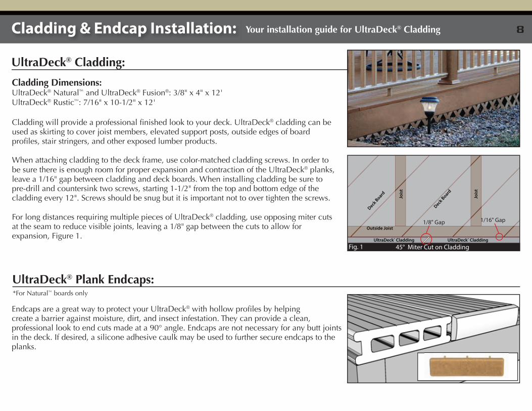
Cladding Dimensions:UltraDeck® Natural™ and UltraDeck® Fusion®: 3/8" x 4" x 12'UltraDeck® Rustic™: 7/16" x 10-1/2" x 12'
Cladding will provide a professional finished look to your deck. UltraDeck® cladding can be used as skirting to cover joist members, elevated support posts, outside edges of board profiles, stair stringers, and other exposed lumber products.
When attaching cladding to the deck frame, use color-matched cladding screws. In order to be sure there is enough room for proper expansion and contraction of the UltraDeck® planks, leave a 1/16" gap between cladding and deck boards. When installing cladding be sure to pre-drill and countersink two screws, starting 1-1/2" from the top and bottom edge of the cladding every 12". Screws should be snug but it is important not to over tighten the screws.
For long distances requiring multiple pieces of UltraDeck® cladding, use opposing miter cuts at the seam to reduce visible joints, leaving a 1/8" gap between the cuts to allow for expansion, Figure 1.
UltraDeck® Cladding UltraDeck® Cladding
Outside Joist
Jois
t
Jois
t
Deck Board
Deck Board
45° Miter Cut on Cladding
Endcaps are a great way to protect your UltraDeck® with hollow profiles by helping create a barrier against moisture, dirt, and insect infestation. They can provide a clean, professional look to end cuts made at a 90° angle. Endcaps are not necessary for any butt joints in the deck. If desired, a silicone adhesive caulk may be used to further secure endcaps to the planks.
Cladding & Endcap Installation: Your installation guide for UltraDeck® Cladding
UltraDeck® Cladding:
UltraDeck® Plank Endcaps:*For Natural™ boards only
Fig. 1
1/8" Gap 1/16" Gap
8
Your installation guide for UltraDeck® Railing
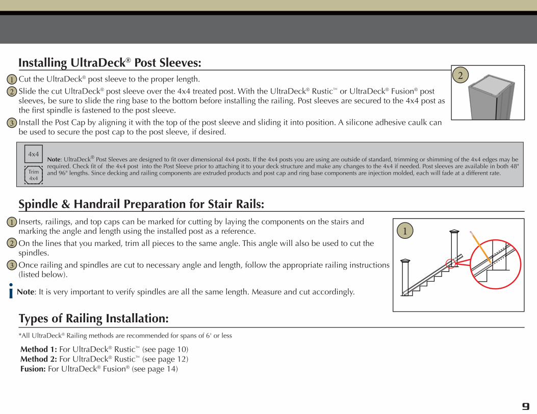
Cut the UltraDeck® post sleeve to the proper length.
Slide the cut UltraDeck® post sleeve over the 4x4 treated post. With the UltraDeck® Rustic™ or UltraDeck® Fusion® post sleeves, be sure to slide the ring base to the bottom before installing the railing. Post sleeves are secured to the 4x4 post as the first spindle is fastened to the post sleeve.
Install the Post Cap by aligning it with the top of the post sleeve and sliding it into position. A silicone adhesive caulk can be used to secure the post cap to the post sleeve, if desired.
Installing UltraDeck® Post Sleeves:
Note: UltraDeck® Post Sleeves are designed to fit over dimensional 4x4 posts. If the 4x4 posts you are using are outside of standard, trimming or shimming of the 4x4 edges may be required. Check fit of the 4x4 post into the Post Sleeve prior to attaching it to your deck structure and make any changes to the 4x4 if needed. Post sleeves are available in both 48" and 96" lengths. Since decking and railing components are extruded products and post cap and ring base components are injection molded, each will fade at a different rate.
12
3
Inserts, railings, and top caps can be marked for cutting by laying the components on the stairs and marking the angle and length using the installed post as a reference.
On the lines that you marked, trim all pieces to the same angle. This angle will also be used to cut the spindles.
Once railing and spindles are cut to necessary angle and length, follow the appropriate railing instructions (listed below).
Spindle & Handrail Preparation for Stair Rails:
General Guidelines for Rail Installation:
1
2
3
Types of Railing Installation:
Method 1: For UltraDeck® Rustic™ (see page 10)Method 2: For UltraDeck® Rustic™ (see page 12)Fusion: For UltraDeck® Fusion® (see page 14)
*All UltraDeck® Railing methods are recommended for spans of 6' or less
1
i Note: It is very important to verify spindles are all the same length. Measure and cut accordingly.
2
4x4
Trim4x4
8
9
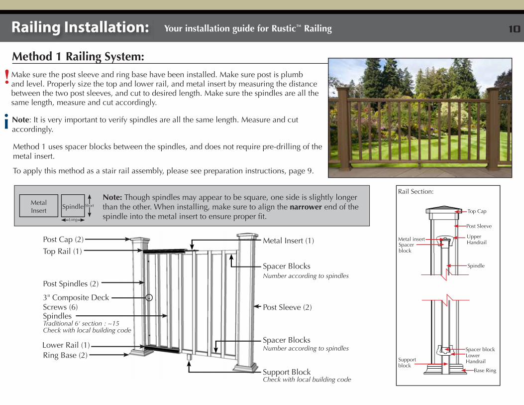
Method 1 Railing System:
Railing Installation: Your installation guide for Rustic™ Railing
!
Method 1 uses spacer blocks between the spindles, and does not require pre-drilling of the metal insert.
Make sure the post sleeve and ring base have been installed. Make sure post is plumb and level. Properly size the top and lower rail, and metal insert by measuring the distance between the two post sleeves, and cut to desired length. Make sure the spindles are all the same length, measure and cut accordingly.
Top Rail (1)
Post Spindles (2)
3" Composite Deck Screws (6)
Lower Rail (1)
Support BlockCheck with local building code
Post Cap (2)
Spindles Traditional 6' section : ~15Check with local building code
Post Sleeve (2)
Spacer Blocks
Spacer BlocksNumber according to spindles
Number according to spindles
Metal Insert (1)
Ring Base (2)
i Note: It is very important to verify spindles are all the same length. Measure and cut accordingly.
To apply this method as a stair rail assembly, please see preparation instructions, page 9.
Top Cap
Post Sleeve
Upper Handrail
Spindle
Base Ring
Spacer blockLower HandrailSupport
block
Rail Section:
Metal insertSpacer block
Note: Though spindles may appear to be square, one side is slightly longer than the other. When installing, make sure to align the narrower end of the spindle into the metal insert to ensure proper fit.
SpindleMetal Insert
Long
Short
10
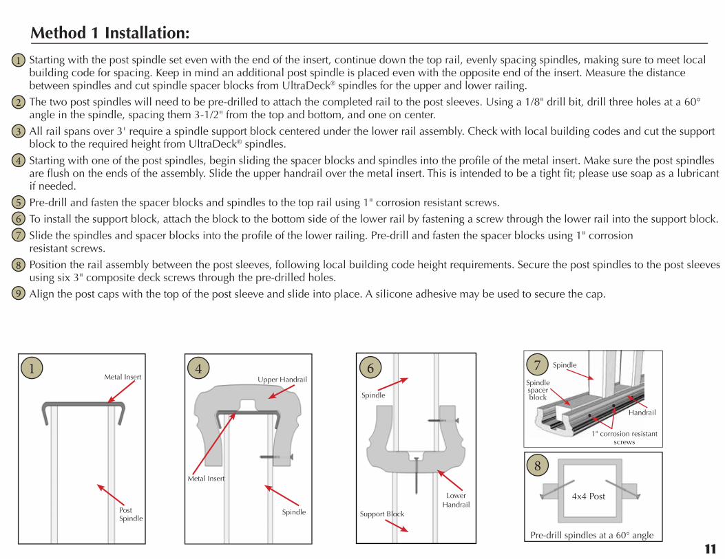
Starting with the post spindle set even with the end of the insert, continue down the top rail, evenly spacing spindles, making sure to meet local building code for spacing. Keep in mind an additional post spindle is placed even with the opposite end of the insert. Measure the distance between spindles and cut spindle spacer blocks from UltraDeck® spindles for the upper and lower railing.
The two post spindles will need to be pre-drilled to attach the completed rail to the post sleeves. Using a 1/8" drill bit, drill three holes at a 60° angle in the spindle, spacing them 3-1/2" from the top and bottom, and one on center.
All rail spans over 3' require a spindle support block centered under the lower rail assembly. Check with local building codes and cut the support block to the required height from UltraDeck® spindles.
Starting with one of the post spindles, begin sliding the spacer blocks and spindles into the profile of the metal insert. Make sure the post spindles are flush on the ends of the assembly. Slide the upper handrail over the metal insert. This is intended to be a tight fit; please use soap as a lubricant if needed.
Pre-drill and fasten the spacer blocks and spindles to the top rail using 1" corrosion resistant screws.
To install the support block, attach the block to the bottom side of the lower rail by fastening a screw through the lower rail into the support block.
Slide the spindles and spacer blocks into the profile of the lower railing. Pre-drill and fasten the spacer blocks using 1" corrosion resistant screws.
Position the rail assembly between the post sleeves, following local building code height requirements. Secure the post spindles to the post sleeves using six 3" composite deck screws through the pre-drilled holes.
Align the post caps with the top of the post sleeve and slide into place. A silicone adhesive may be used to secure the cap.
Metal Insert
Spindle
Upper Handrail
1
2
3
4
567
8
9
Method 1 Installation:
4x4 Post
8
4
Spindle
Support Block
Lower Handrail
6 Spindle
Spindle spacer block
Handrail
1" corrosion resistant screws
7
Pre-drill spindles at a 60° angle
Metal Insert
PostSpindle
1
10
11
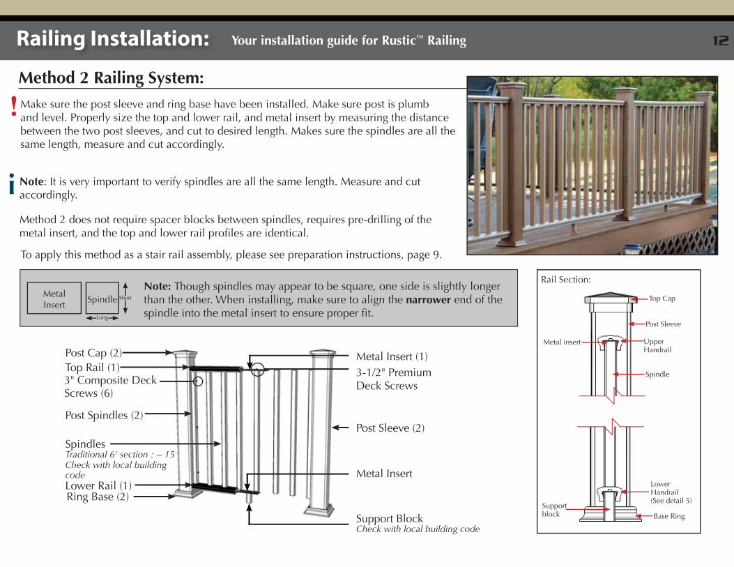
Method 2 Railing System:
Railing Installation: Your installation guide for Rustic™ Railing
!Make sure the post sleeve and ring base have been installed. Make sure post is plumb and level. Properly size the top and lower rail, and metal insert by measuring the distance between the two post sleeves, and cut to desired length. Makes sure the spindles are all the same length, measure and cut accordingly.
Method 2 does not require spacer blocks between spindles, requires pre-drilling of the metal insert, and the top and lower rail profiles are identical.
Top Rail (1)
Post Spindles (2)
3" Composite Deck Screws (6)
Lower Rail (1)
Support BlockCheck with local building code
Post Cap (2)
Spindles Traditional 6' section : ~ 15Check with local building code
Post Sleeve (2)
Metal Insert
3-1/2" Premium Deck Screws
Metal Insert (1)
Ring Base (2)
i Note: It is very important to verify spindles are all the same length. Measure and cut accordingly.
To apply this method as a stair rail assembly, please see preparation instructions, page 9.
Rail Section:
Top Cap
Post Sleeve
Upper Handrail
Spindle
Base RingSupport block
Lower Handrail(See detail 5)
Metal insert
Note: Though spindles may appear to be square, one side is slightly longer than the other. When installing, make sure to align the narrower end of the spindle into the metal insert to ensure proper fit.
SpindleMetal Insert
Long
Short
12
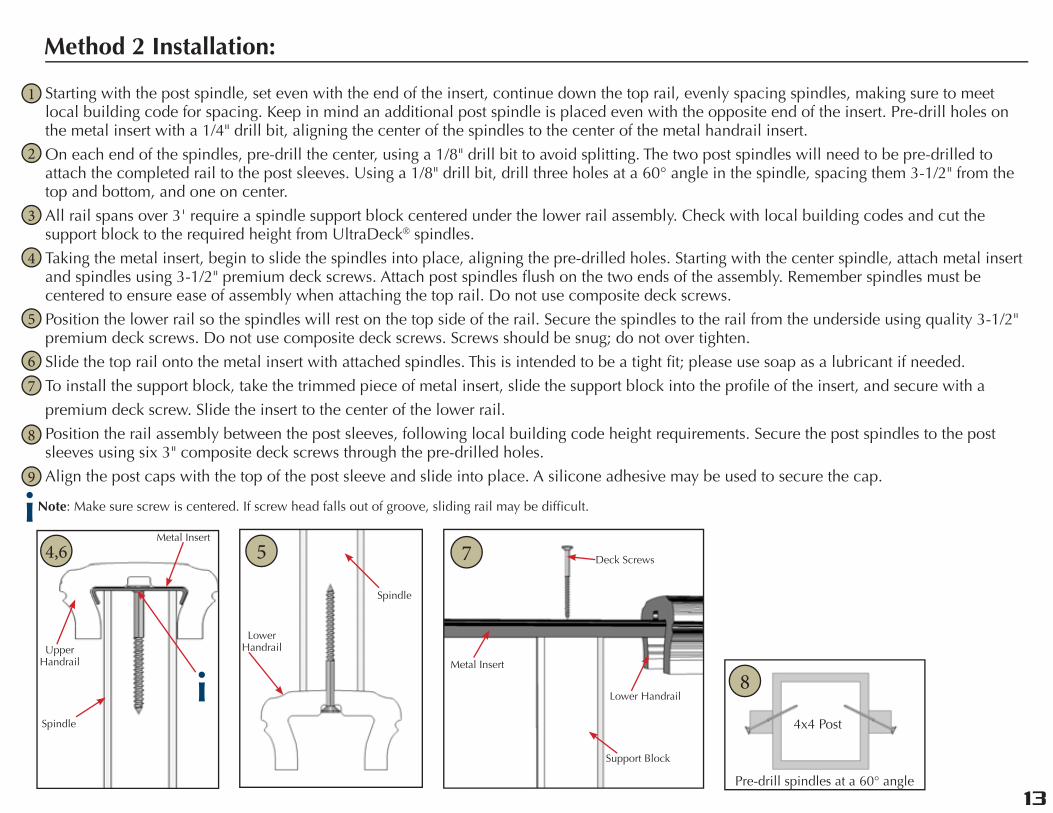
Starting with the post spindle, set even with the end of the insert, continue down the top rail, evenly spacing spindles, making sure to meet local building code for spacing. Keep in mind an additional post spindle is placed even with the opposite end of the insert. Pre-drill holes on the metal insert with a 1/4" drill bit, aligning the center of the spindles to the center of the metal handrail insert.
On each end of the spindles, pre-drill the center, using a 1/8" drill bit to avoid splitting. The two post spindles will need to be pre-drilled to attach the completed rail to the post sleeves. Using a 1/8" drill bit, drill three holes at a 60° angle in the spindle, spacing them 3-1/2" from the top and bottom, and one on center.
All rail spans over 3' require a spindle support block centered under the lower rail assembly. Check with local building codes and cut the support block to the required height from UltraDeck® spindles.
Taking the metal insert, begin to slide the spindles into place, aligning the pre-drilled holes. Starting with the center spindle, attach metal insert and spindles using 3-1/2" premium deck screws. Attach post spindles flush on the two ends of the assembly. Remember spindles must be centered to ensure ease of assembly when attaching the top rail. Do not use composite deck screws.
Position the lower rail so the spindles will rest on the top side of the rail. Secure the spindles to the rail from the underside using quality 3-1/2" premium deck screws. Do not use composite deck screws. Screws should be snug; do not over tighten.
Slide the top rail onto the metal insert with attached spindles. This is intended to be a tight fit; please use soap as a lubricant if needed.
To install the support block, take the trimmed piece of metal insert, slide the support block into the profile of the insert, and secure with a
premium deck screw. Slide the insert to the center of the lower rail.
Position the rail assembly between the post sleeves, following local building code height requirements. Secure the post spindles to the post sleeves using six 3" composite deck screws through the pre-drilled holes.
Align the post caps with the top of the post sleeve and slide into place. A silicone adhesive may be used to secure the cap.
Method 2 Installation:
1
2
3
4
5
67
8
9
Spindle
Metal Insert
Upper Handrail
Lower Handrail
Spindle
Metal Insert
Support Block
Lower Handrail
Deck Screws4,6 7
4x4 Post
8
5
Pre-drill spindles at a 60° angle
iNote: Make sure screw is centered. If screw head falls out of groove, sliding rail may be difficult.
i
12
13
Railing Installation: Your installation guide for Fusion® Railing
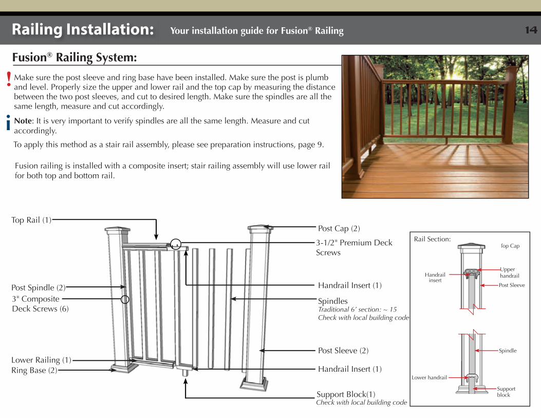
Fusion® Railing System:
!Make sure the post sleeve and ring base have been installed. Make sure the post is plumb and level. Properly size the upper and lower rail and the top cap by measuring the distance between the two post sleeves, and cut to desired length. Make sure the spindles are all the same length, measure and cut accordingly.
i Note: It is very important to verify spindles are all the same length. Measure and cut accordingly.
To apply this method as a stair rail assembly, please see preparation instructions, page 9.
Fusion railing is installed with a composite insert; stair railing assembly will use lower rail for both top and bottom rail.
Post Cap (2)
Post Sleeve (2)
Handrail Insert (1)
3-1/2" Premium Deck Screws
Top Rail (1)
Handrail Insert (1)Post Spindle (2)
Spindles3" Composite Deck Screws (6) Traditional 6’ section: ~ 15
Check with local building code
Support Block(1)Check with local building code
Lower Railing (1)Ring Base (2)
Upper handrailHandrail
insert
Lower handrail
Spindle
Support block
Post Sleeve
Top CapRail Section:
14
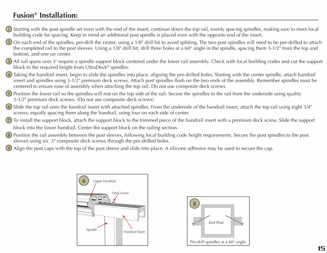
Starting with the post spindle set even with the end of the insert, continue down the top rail, evenly spacing spindles, making sure to meet local building code for spacing. Keep in mind an additional post spindle is placed even with the opposite end of the insert.
On each end of the spindles, pre-drill the center, using a 1/8" drill bit to avoid splitting. The two post spindles will need to be pre-drilled to attach the completed rail to the post sleeves. Using a 1/8" drill bit, drill three holes at a 60° angle in the spindle, spacing them 3-1/2" from the top and bottom, and one on center.
All rail spans over 3' require a spindle support block centered under the lower rail assembly. Check with local building codes and cut the support block to the required height from UltraDeck® spindles.
Taking the handrail insert, begin to slide the spindles into place, aligning the pre-drilled holes. Starting with the center spindle, attach handrail insert and spindles using 3-1/2" premium deck screws. Attach post spindles flush on the two ends of the assembly. Remember spindles must be centered to ensure ease of assembly when attaching the top rail. Do not use composite deck screws.
Position the lower rail so the spindles will rest on the top side of the rail. Secure the spindles to the rail from the underside using quality 3-1/2" premium deck screws. (Do not use composite deck screws)
Slide the top rail onto the handrail insert with attached spindles. From the underside of the handrail insert, attach the top rail using eight 3/4" screws, equally spacing them along the handrail, using four on each side of center.
To install the support block, attach the support block to the trimmed piece of the handrail insert with a premium deck screw. Slide the support
block into the lower handrail. Center the support block on the railing section.
Position the rail assembly between the post sleeves, following local building code height requirements. Secure the post spindles to the post sleeves using six 3" composite deck screws through the pre-drilled holes.
Align the post caps with the top of the post sleeve and slide into place. A silicone adhesive may be used to secure the cap.
Fusion® Installation:
1
2
3
4
5
6
7
8
9
4x4 Post
Pre-drill spindles at a 60° angle
8
Deck Screw
Handrail InsertSpindle
Upper Handrail6
14
15
www.midwestmanufacturing.com
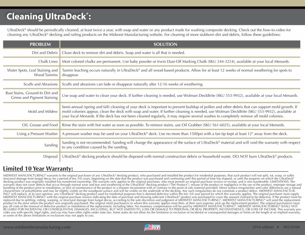
MIDWEST MANUFACTURING® warrants to the original purchaser of any UltraDeck® decking product, who purchased and installed the product for residential purposes, that such product will not split, rot, warp, or suffer structural damage from fungal decay for a period of ten (10) years, beginning on the date that the product was purchased and continuing until this period of time has elapsed, or until the property on which the UltraDeck® decking product was originally installed has transferred ownership. The warranty only applies to the original purchaser, who must present an original purchase invoice or receipt, and is non-transferable. LIMITATIONS. The warranty does not cover defects that occur through normal wear and tear and weathering of the UltraDeck® decking product (“The Product”), misuse of the product or negligence in the use of the product, improper storage and handling of the product prior to installation, or lack of maintenance of the product in a manner inconsistent with or contrary to the point of sale material provided. Minor surface irregularities and color differences are a natural characteristic of polyethylene and may be slightly visible on the woodgrain surface and will be visible on the underside of the decking. Any such irregularities do not constitute a product defect. MIDWEST MANUFACTUR-ING® will replace, at its own opinion, any UltraDeck® decking product used for residential purposes that is deemed defective within the ten (10) year period for which this warranty applies. The original purchaser must supply MIDWEST MANUFACTURING® ® product was purchased to cover the amount claimed to be defective. If the product must be replaced due to splitting, rotting, warping, or structural damage from fungal decay, according to the sole discretion and judgment of MIDWEST MANUFACTURING®, MIDWEST MANUFACTURING® will send the replacement product to the store where the product was originally purchased. The original retail purchaser(s) to whom this warranty applies must then, at their own expense, pick up the replacement product. The original purchaser(s) must pay all costs of the removal of defective product or installation of the replacement, including labor. No monetary compensation will be paid by MIDWEST MANUFACTURING®. MIDWEST MANUFACTURING® SHALL NOT BE LIABLE FOR INCIDENTAL OR CONSEQUENTIAL DAMAGES, INCLUDING, BUT NOT LIMITED TO, LOSS OR DAMAGE TO PERSONAL OR REAL PROPERTY, INCONVENIENCE, OR LOSS OF INCOME. This warranty pro-
so some of the above limitations or exclusions may not apply to you.
Limited 10 Year Warranty:
PROBLEM SOLUTION
Clean deck to remove dirt and debris. Soap and water is all that is needed.
Most colored chalks are permanent. Use baby powder or Irwin Dust-Off Marking Chalk (SKU 244-3224), available at your local Menards.
Tannin leaching occurs naturally in UltraDeck® and all wood-based products. Allow for at least 12 weeks of normal weathering for spots to disappear.
Scuffs and abrasions can fade or disappear naturally after 12-16 weeks of weathering.
Use soap and water to clean your deck. If further cleaning is needed, use Wolman DeckBrite (SKU 553-9932), available at your local Menards.
Dirt and Debris
Chalk Lines
Water Spots, Leaf Staining and Wood Tannins
Scuffs and Abrasions
Rust Stains, Ground-In Dirt and Grime and Pigment Staining
Semi-annual (spring and fall) cleaning of your deck is important to prevent buildup of pollen and other debris that can support mold growth. If mold colonies appear, clean the deck with soap and water. If further cleaning is needed, use Wolman DeckBrite (SKU 553-9932), available at your local Menards. If the deck has not been cleaned regularly, it may require several washes to completely remove all mold colonies.
Mold and Mildew
A pressure washer may be used on your UltraDeck® deck. Use no more than 1500psi with a fan tip kept at least 12" away from the deck.Using a Pressure Washer
Rinse the stain with hot water as soon as possible. To remove stains, use Oil Grabber (SKU 561-6025), available at your local Menards.Oil, Grease and Food
Sanding is not recommended. Sanding will change the appearance of the surface of UltraDeck® material and will void the warranty with respect to any condition caused by the sanding.
UltraDeck® decking products should be disposed with normal construction debris or household waste. DO NOT burn UltraDeck® products.
Sanding
Disposal
UltraDeck® should be periodically cleaned, at least twice a year, with soap and water or any product made for washing composite decking. Check out the how-to-video for cleaning any UltraDeck® decking and railing products on the Midwest Manufacturing website. For cleaning of more stubborn dirt and debris, follow these guidelines:
Cleaning UltraDeck®: