Embed Size (px)
Citation preview
E. M. CampbellDeputy Director,University of RochesterLaboratory for Laser Energetics
Presentation at George Washington University
Washington, DC14 December 2015
Ultrahigh Brightness Laser Development at the Laboratory for Laser Energetics
1
Seed
Pump
Time
Plasma wave
Depleted pump
Amplified
seed
EP OPAL beamline
EP OPAL compressorUltra-broadband front end
OMEGA EP OPAL
Short-pulsetransport
and focusing

Collaborators
D. Haberberger, A. Davies, S.-W. Bahk, J. Bromage, J. D. Zuegel, and D. H. Froula
University of RochesterLaboratory for Laser Energetics
J. Sadler and P. A. Norreys
University of Oxford
...and many others
2

LLE and collaborators are pursuing two paths for the development of multipetawatt, high-brightness lasers
Outline
I2270
• Raman plasma-wave amplifier
– parametric amplification of a short seed pulse by stimulated Raman scattering in a matched plasma medium
• Optical parametric amplifier (OPA) pumped by multikilojoule Nd:glass laser
– ~12-kJ (0.532-nm), 2.5-ns pulse pump (OMEGA EP) for OPA
– large-aperture (80-cm), high-damage (300-mJ/cm2) grating for pulse compression [chirped-pulse amplification (CPA)]
3

Raman amplifiers: Exploit the nonlinear physics of laser–plasma interactions (LPI)’s
I2271
4
• Intense laser radiation can excite electrostatic waves in plasmas
Laser light propagates through the plasma
Oscillations in the plasma begin to radiate scattered light (linear Thomson scatter)
The beating of the two light waves creates a ponderomotive force, pushing the particles into the troughs of the envelope
If the bunching of the particles matches an electrostatic mode, the three waves become resonant and grow
E E E E
Electrostatic plasma wave
Step 1
Step 2
Step 3
Step 4

If there is a resonance with electrostatic modes of the plasma, instabilities can result (example SRS, SBS)
I2272
5
Raman amplifiers are “seeded” SRS.
• Simulated Raman scattering (SRS)
• Simulated Brillouin scattering (SBS)
• SRS occurs when:
• SBS occurs when:
Laser light Electron plasma wave (EPW)
Scattered-light wave
Laser light Ion sound wave (IAW)
Scattered-light wave
k k kEPW
EPW0 2
0 2
~ ~ ~= +
= +
k k kIAW
IAW0 1
0 1
~ ~ ~= +
= +

National Plasma Science reports have identified plasma-wave (Raman) amplifiers as a potential for the next generation of pettawatt-class lasers
I2273
6
Seed
Pump
Time
Plasma wave
Depleted pump
Amplified
seed
High-energy compression gratings are NOT required.
Manley–Rowe (energy and momentum conservation)
• ~pump = ~seed + ~EPW
• kpump = kseed + kEPW
• Plasma [EPW (dne/ne ~1%)] is the medium that transfers energy from a long-pulse (ns) pump, high-energy laser to a short-pulse (~15 fs), low-energy seed laser

Raman amplifiers require understanding and control of nonlinear plasma physics
I2274
• Goal: efficient energy transfer from long pulse pump to seed
– pump depletion
• Challenges that limit efficiency and resonance condition and brightness (focusability)
– filamentation– frequency detuning– amplitude of EPW
- wave breaking- mode coupling
– competition with plasma-wave interactions- Raman forward scattering of the seed pulse- Raman backscatter of the pump pulse
7
Pump intensity and plasma density are key controlling parameters.
– /v k n n
c1ph
e c0
0~= =
– /index of refractionn n n1 /plasma e c
1 2=^ ^h h
Low-light pressure
Low-light pressure
Laser“Hotspot”
High-lightpressure Laser light
self-focuses
Electrondensity

Multidimensional particle-in-cell (PIC) codes have identified operating parameters for efficient pump-seed conversion
I2275
• Strategy
– maximize Raman amplification of the pump
- limit forward Raman scattering (gain < 10)
– limit filamentation of the seed (gain < 10)
• Strategy defines experimental parameters
– Ipump < 5 × 10¹⁴ W/cm2
– 2.5 × 10¹⁸ < ne < 5 × 1018 cm–3
– Iseed < 4 × 1017 cm3
8
n/n
c
10–3
10–2
1012 1013
Pump intensity (W/cm2)
1014 1015
30
25
20
15
10
5
0
psto fsps
to fs
nsto ps
nsto ps
3535 2020
6060
40404545
Max
imu
m p
rop
agat
ion
dis
tan
ce (
cm)

1150
1140
1130
1120
1110
1100
109031 5 7
Plasma density (×1018 cm–3)
See
d w
avel
eng
th (n
m)
1.00.8
0.6
0.4
0.2
0.01000 1050 1100950 1150
Wavelength (nm)
Sp
ectr
a (n
orm
aliz
ed)
SignalIdler
A tunable seed laser is being built to access the optimal Raman amplification regime for a 1053-nm pump laser
E23502b
9
The plasma density and seed wavelength will be varied to optimize amplification.
20pe0
~~
=
peseed 0 -~ ~ ~=
14pe0
~~
=
PumpMulti-Terawatt (MTW) Laser SystemNd:glass: 1053 nmEmax = 75 JDt = 25 ps
SeedOptical parametric amplifier line (OPAL)Emax = 50 mJ (1100 nm to 1300 nm)Dt ~ 0.1 ps

Research at LLE is exploring the laser–plasma physics with the goal of demonstrating an efficient petawatt plasma-wave amplifier
E23501a
• Optical plasma densities– tunable pump and seed wavelengths
• Laser pump energy– ~75 J
• High-intensity seed pulse– Eseed ~ 75 mJ– Iseed ~ 2 × 10¹⁴ W/cm3
• Homogeneous plasma– 4-cm-long gas cell– cold plasma (<70 eV)
- limit EPW wave breaking
• Sophisticated diagnostics– optical Thomson scattering
- EPW characterization– interferometry
- plasma density– spectral phase interferometry (SPIDER)
- phase and electric field of amplified laser pulse
10
*Epump/Eseed ~104 to 106 (limits pump depletion and efficiency).
1.1
***
1.0
0.9
0.8
0.7
0.6
0.55 10 15 20
Plasma density (1018 cm–3)
~0/~pe = 14~0/~pe = 20Previous experimentsLLE experiments
Pu
mp
wav
elen
gth
(n
m)

The goal of the present effort is to demonstrate the feasibility of a plasma-wave amplifier in the pump-depletion regime
I2276
11
The next-generation ultrahigh-power, short-pulse system at LLE could use plasma-wave amplification as the final amplifier to achieve 100 PW.
10 J, 15 fs
MTW OPAL
EP OPAL100 J, 20 fs, 5 PW
20 kJ, 20 fs
1 exawatt1025 W/cm2
30 kJ, 500 ps
Plasma-wavepump
Plasma-waveamplifier
OMEGA EP

LLE and collaborators are pursuing two paths for the development of multipetawatt, high-brightness lasers
Outline
I2270a
• Raman plasma-wave amplifier
– parametric amplification of a short seed pulse by stimulated Raman scattering in a matched plasma medium
• Optical parametric amplifier (OPA) pumped by multikilojoule Nd:glass laser
– ~12-kJ (0.532-nm), 2.5-ns pulse pump (OMEGA EP) for OPA
– large-aperture (80-cm), high-damage (300-mJ/cm2) grating for pulse compression [chirped-pulse amplification (CPA)]
12

LLE is developing a concept for a >50-PW single-aperture laser based on pumping an OPA with two OMEGA EP beamlines
I2286
• The EP OPAL design at full scale would produce 75 PW (1.5 kJ at 20 fs) with high contrast
13
OMEGA EPbeamlines
EP OPAL beamline
EP OPAL compressor
Ultra-broadbandfront end (UFE)
Short-pulse transport and
focusing1234

Only KDP** and DKDP*** can be grown in boule sizes large enough for kilojoule amplifiers.
Nd:glass lasers can pump large optical parametric amplifiers, producing bandwidth for sub-20-fs pulses*
E24282b
14
*I. N. Ross et al., Opt. Commun. 144, 125 (1997); V. V. Lozhkarev et al., Laser Phys. 15, 1319 (2005).**KDP: potassium dihydrogen phosphate
***DKDP: deuterated potassium dihydrogen phosphate
Nonlinear crystal |(2)Signal
Amplifiedsignal
Signal gain when wave vectors
conserve energy AND momentum
(Angles exaggerated for clarity)
Idler
OMEGA EPpump
Signal bandwidth
kPkS kI 800 850 900 950 1000 1050
0
500
1000
Wavelength (nm)
DKDP small-signal gain2-GW/cm2 pump,
45-mm crystal thickness
Sm
all-
sig
nal
gai
n
170 nm

The multikilojoule Nd:glass OMEGA EP laser can serve as a pump for an OPA
I2287
• OMEGA EP
– four beams
- ~50 kJ at 1.05 nm
- >25 kJ at 0.53 nm
- >16 kJ at 0.35 nm
15

EP OPAL is an OPCPA* system, consisting of an ultra-broadband front end, large-aperture NOPA’s,** a compressor, and focuses on the OMEGA EP target chamber
E24287b
16
Beamline 36.3 kJ2.5 ns
NOPA7
Beamline 4
NOPA6
6.3 kJ2.5 ns
NOPA5 pump
NOPA5
100 J2.5 ns
OMEGA EP
Ultra-broadband front end(NOPA1 to NOPA4)
Beamline 1pulses to
EPTC
Beamline 2ps (IR)
+ns (UV)
EP OPAL beamline
0.25 J, 2.5 ns, 160 nm
Compressor
1.6 kJ, 20 fs
OMEGA EPtarget
chamber(EPTC)
~75 PW~1024 W/cm2
1053 nm527 nm810 to 1010 nm
*OPCPA: optical parametric chirped-pulse identification**NOPA: noncollinear optical parametric amplifier

Schematic of OPCPA pumped by OMEGA EP
E24288a
17
*VSF: vacuum spatial filter**FWHM: full width at half maximum
Pump parameters for all noncollinear optical parametric amplifiers (NOPA’s): 527 nm, 2.5 ns, 2 GW/cm2
80-cm beam (FW 1%)300 mJ/cm2 at gratings" 75 PW
UFE
Pu
mp
/sig
nal
Pu
mp
/sig
nal
Pu
mp
/sig
nal
Pu
mp
/sig
nal
Co
mp
ress
or
NO
PA6
NO
PA7
VSF*8×
VSF1.0×
VSF2.2×
NOPA5Pump/signal
Pump/signal
Pump in: 4.5 cm (FWHM**) 100 J Signal out: 25 J
Pump in: 35.5 cm (FWHM) 6.3 kJ Signal out: 1.5 kJ
Pump in: 35.5 cm (FWHM) #6.3 kJ Signal out: #3 kJ
Signal in: 73 cm (FWHM) 2.3 kJ Signal out: 20 fs 1.6 kJ 300 mJ/cm2

A single-aperture >50-PW laser will require advances in several areas
I2288
• Advanced broadband, efficient, damage-resistant gratings
• Ultra-broadband wavefront control and focusing
• Large-aperture, high deuterated DKDP
• Damage-resistant short-pulse (broadband) coatings
• Diagnostics
• Ultra-broadband dispersion control
• NOPA gain control and adjustment
• Ultra-broadband front end
18
LLE is developing a scaled facilty (MTW OPAL) to develop/demonstate ultra-peak-power OPCPA lasers.

MTW OPAL has several technical and scientific goals
E24300b
19
Goal 1: Develop and demonstrate laser technologies required for EP OPAL
Goal 2: Build operational experience with a mid-scale user facility
Goal 3: Grow a science program with ultrashort pulses

Although MTW OPAL is significantly smaller than EP OPAL, it uses the same technologies
E24301a
20
Parameter MTW OPAL EP OPAL
Pulse width (FWHM) 15 fs 20 fs
Compressor beam size (FW 1%) 9 cm 60 to 80 cm
Compressor output energy 7.5 J 300 to 1600 J
Power 0.5 PW 14 to 75 PW
Technologies MTW OPAL EP OPAL
Advanced grating types { {
Achromatic image relays { {
DKDP amplifiers { {
Short-pulse coatings { {
Short-pulse diagnostics { {

The MTW OPAL system uses the existing MTW laser at LLE to pump the final amplifier (NOPA5)
E24302a
21
*SHG: second-harmonic generation
MTW front end+6 nm FWHM
OPCPA pumplaser
UFE+200 nm FWHM
Radial-group-delay compensator
(RGDC)
OPCPA Rod amplifierDisk amplifier
SHGtable
NOPA5NOPA4
32
1
Picosecondcompressor
New targetchamber
Femtosecondcompressor
MTW targetchamber
SHG*
Laser Development Laboratory (LDL)
LDL-Annex
Activated
527 nm 830 to 1010 nm 1053 nm
Operational
Underconstruction
Ordered(except crystal)
Optical designin progress
Underconstruction
TestingUnder
construction

The UFE consists of a white-light–seeded chain of NOPA’s and a 1.5-ns stretcher
E24303a
22
Oscillator
1053 nm160 fs
Delayand sync
CompressorNOPA12~
2~
NOPA2
NOPA3
Dazzler™
Beam relay
Stretcher
WLC*
Yb fiber
Fiber CPA pump laser
250 fs, 14 nJ, 500 kHz 5 nJ, 0.3 ps
0.3 mJ, 1.5 ns
11 ps, 70 mJ, 5 Hz
Stretch
Nd:YLF pump laser
Regen with self-phase
modulation (SPM)compensation
527 nm 810 to 1010 nm 1053 nm
Poweramplifier
*WLC: white-light continuum

The prototype UFE is operational and available to support MTW OPAL development
E24304a
23
0
0
–5
–5
5
5
x axis (mm)
y ax
is (
mm
)
Stretcher near field
00
40
60
120
160
200
0
500–500
400
–400
x (nrad)
y (n
rad
)
Stretcher far field
Diffractionlimit FWHM
Symmetric withnegligible wings
Delay (ps)
Prestretch temporal contrast
0
10–16
10–12
10–8
10–4
1
–200 200
Diagnosticnoise floor NOPA1
+ NOPA2+ NOPA3
†††
Diagnosticreflection
†
Cro
ss-c
orr
elat
ion
(d
B)
NOPA1 pulse afterprism compressor
0
Time (fs)
Inte
nsi
ty
(arb
itra
ry u
nit
s)0.0
0.5
1.0
50–50
Fouriertransform
limit(11.9 fs)
Measured(12.8 fs)
Wavelength (nm)
Sp
ectr
um
(a
rbit
rary
un
its)
Stretcher output spectrum
900
210 nm
10008000
40
80
120mean!rms*
• UFE has been thoroughly characterized
• Additional measurements will be required after the full system is built (e.g., recompression)
*rms: root mean square

Activation of the NOPA4 stages and transport to NOPA5 (DKDP final amplifier) will be completed this year
E24305a
24
SHGtable
NOPA5 pump and signal transporthave been designed and ordered
NOPA4 stages areunder construction
NOPA5

A compressor chamber is being designed for multiple functions
E24306a
25
Short-pulse diagnostics
Double plasmamirror
To target chamber
Periscope
Achromatic image relay
Compressor
Periscope
From NOPA5
• Demonstrate an achromatic relay (2× magnification)
• Recompress pulse from 1.5 ns to 15 fs
• Test gold (p-pol) and hybrid gratings (s-pol)
• Demonstrate femtosecond coatings (s- and p-pol)
• Develop a double-plasma mirror option for improved temporal contrast (~100×)
• Sample beams for short- pulse diagnostics
Optical design is underway and a full optomechanical design must be completed in 2016.

After MTW OPAL is completed, the technology readiness levels (TRL’s) for the main technical challenges will have improved to TRL 5–TRL 6
E24309a
26
Technical challenge Current TRL
MTW OPAL Progress
Advanced gratings 2 5 Technology concept " Lab-scale prototype
Ultra-broadband wavefront control and focusing 2 5 Technology concept " Lab-scale prototype
Large-aperture, highly deuterated DKDP 2 5 Technology concept " Lab-scale prototype
Short-pulse coatings 3 5 Active R & D " Lab-scale prototype
Short-pulse diagnostics 3 6 Active R & D " Pilot-scale prototype
Ultra-broadband dispersion control 3 6 Active R & D " Pilot-scale prototype
NOPA gain adjustment 2 6 Technology concept " Pilot-scale prototype
Ultra-broadband front end 5 6 Lab-scale prototype " Pilot-scale prototype

LLE vision: three world-class user laser facilities
I2289
• OMEGA (60 beams)
– 30 kJ
– 30 TW
– 0.35 nm
27
• OMEGA EP (four beams)
– four beams (option 1)
- ~16 kJ
- ~8 TW
- 0.35 nm
– two beams (option 2)
- ~2 kJ
- ~10 ps
- 1.05 nm
• EP OPAL (one beam)
– one beam
- ~1.5 kJ
- 20 fs
- ~0.83 to 1 nm

Backup
28

A number of petawatt facilities are operational, but multipetawatt facilities are only in development
E24284a
29
Name Facility Technology Peak power Status
Apollon-10P
Laboratoire pour l’Utilisation des Lasers Intenses + Laboratoire d’Optique Appliquée +
Institute Optique
OPCPA + Ti:sapphire 5 PW Under
construction
L4
Extreme Light Infrastructure-CZ +
National Energetics
OPCPA + Nd:glass 10 PW Under
contract
–Extreme Light
Infrastructure-NP + Thales
OPCPA + Ti:sapphire 2 × 10 PW Under
contract
Vulcan 20 PWRutherford Appleton
Laboratory (RAL)OPCPA 20 PW On hold
Exawatt Center for
Extreme Light Studies
Institute of Applied Physics (IAP) OPCPA 12 × 15 PW Concept

The UFE consists of a white-light–seeded chain of NOPA’s and a 1.5-ns stretcher
E24303b
30
Oscillator
1053 nm160 fs
Delayand sync
CompressorNOPA12~
2~
NOPA2
NOPA3
Dazzler™
Beam relay
Stretcher
WLC
Yb fiber
Fiber CPA pump laser
250 fs, 14 nJ, 500 kHz 5 nJ, 0.3 ps
0.3 mJ, 1.5 ns
11 ps, 70 mJ, 5 Hz
Stretch
Nd:YLF pump laser
Regenwith SPM
compensation
527 nm 810 to 1010 nm 1053 nm
Poweramplifier
A UFE prototype has been built and testing is underway
E24316a
31
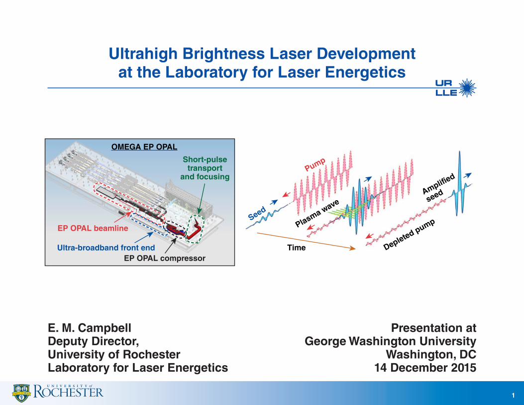
• All parameters measured so far meet requirements
• Testing will be ongoing
– operational maturity
– spectral phase control for recompression
– temporal contrast and prepulses
• A new stretcher is required for an EP OPAL-scale compressor
– prototype: 1.5 ns/200 nm (7.5 ps/nm)
– EP OPAL: 2.5 ns/150 nm (16.6 ps/nm)
Ultra-broadband front end for MTW OPAL
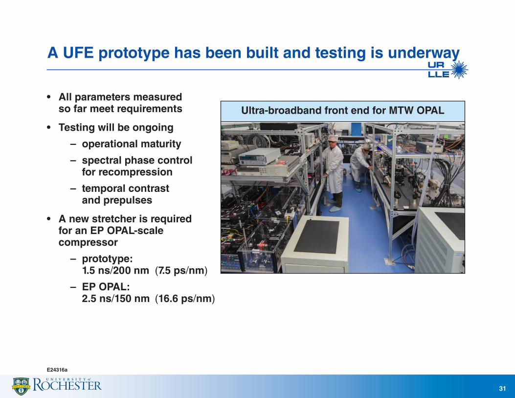
High power and intensity require large-aperture beams that are tightly focused
E24283a
32
• Damage thresholds for femtosecond mirrors and gratings are in the 100’s of mJ/cm2 range (cf., few J/cm2 for ps)
• Tight focal spots place challenging requirements on the beam wavefront and the final-focusing optics
20
10
30
50
70
90
40 60
Beam full width at 1% (cm)
Power versuscompressor-beam size
Pea
k p
ow
er (
PW
)
80
Grating fluence = 300 mJ/cm2
100 mJ/cm2
200 mJ/cm2
20-fs pulse (FWHM)
43
2
4
6
8
10
5 6 6 8
Focal spot FWHM (nm)
Intensity versusfocal-spot width
Inte
nsi
ty (
× 1
023
W/c
m2 )
9 10
P = 75 PW
I = P/rR2
50 PW
25 PW

EP OPAL performance depends on the grating fluence and compressor beam size
E24286d
33
Grating fluence (20 fs)
100 mJ/cm2
Compressor beam size (FW 1%)
60 × 60 cm
Diagonal for 45° angle of incidence 110 cm
Compressor output energy 300 J
f-number and focal spot (nm)
f/6 13
f/1.3 4.2
Energy on target 290 J 230 J
Power 14 PW 12 PW
Intensity (W/cm2) 1 × 10²² 9 × 10²²
300 mJ/cm2
60 × 60 cm
110 cm
900 J
f/6 13
f/1.3 4.2
860 J 700 J
43 PW 35 PW
3 × 10²² 3 × 10²³
300 mJ/cm2
80 × 80 cm
149 cm
1600 J
f/4.6 10
f/1 3.2
1500 J 1200 J
75 PW 62 PW
1 × 10²³ 8 × 10²³
Advancedgratings
Increasedbeam size
Limited by size of current optics fabrication Full scale

Challenges remain to scale femtosecond coating capability for meter-scale laser applications
G10251c
34
• Current uniformity for 1 m " masks with phase discontinuities
• Scaling femtosecond system geometry " 3.5-m chamber
• High film stresses for fully dense coatings
• m/4 on a 1-m optic would require ~16-cm thickness (4-nm-thick coating)
• Match the dispersion over a curved optic aperture
• Enhanced/protected metals are preferred with sufficient laser-damage thresholds
Laser-damage thresholds at the correct pulse length, spectral bandwidth, and large aperture are critical to successful system scale-up.

Enhanced-metal coatings have been developed for the compressed-pulse section
E24318a
35
• Several practical benefits for short-pulse transport – femtosecond damage thresholds comparable to dielectric mirrors – s- or p-polarized beam – low group-delay dispersion, stress-induced wavefront and sensitivity
to coating thickness
R (p-pol, 810 to 1010 nm) >97.4% >98.6% >99.3%GDD** (810 to 1010 nm) 2 fs2 13 fs2 35 fs2
LDT (N:1, 800 nm, 59 fs) 0.60 J/cm2 0.68 J/cm2 0.49 J/cm2
HfO2/SiO2: larger band gap
versus Nb2O5 for improved LDT*Cu: environmental
durability/adhesion
Al2O3: adhesion,environmental
protection
Ag: high %R
Nb2O5/SiO2:maximum bandwidth
and reflectivity
SiO2
Nb2O5
AgCuAl2O3
HfO2Nb2O5
*LDT = laser-damage threshold**GDD = group-delay dispersion

Intermediate power levels are possible with smaller optics and two amplifiers
E24289a
36
Pump parameters for all NOPA’s: 527 nm, 2.5 ns, 2 GW/cm2
60-cm beam (FW 1%)100 mJ/cm2 at gratings" 14 PW300 mJ/cm2 (with NOPA7)" 43 PW
UFE
Pu
mp
/sig
nal
Pu
mp
/sig
nal
Pu
mp
/sig
nal
Co
mp
ress
or
NO
PA6
NO
PA7
VSF6×
VSF1.0×
VSF2.2×
Pu
mp
/sig
nal
Pump in: 4.5 cm (FWHM) 100 J Signal out: 25 J
Pump in: 26.6 cm (FWHM) #3.5 kJ Signal out: #0.88 kJ
Signal in: 55 cm (FWHM) 0.43 kJ Signal out: 20 fs 0.30 kJ 100 mJ/cm2
NOPA5Pump/signal
Pump/signal
• The full-scale infrastructure would be built for the NOPA crystals, compressor gratings, and mirrors
• Sub-aperture optics could be used for a >10-PW system during the early stages of operation

To support the science program, a concept for a joint target area is being developed
E24310a
37
• A target area will be added west of LDL
• Both MTW and OPAL beams will be available for experiments
• The existing “Raman chamber” is shown
• Additional shielding, similar to what is used on MTW (5 cm of lead), would enable a large number of shots Joint target
chamber
f/20
f/2
OPAL Single shot, 7.5 J, 15 fs
(5 Hz, 50 mJ, 15 fs)
MTWSingle shot,50 J, ~1 ps
Room 136
LDL
LDL Annex
Height =37.5 in.
NOPA5 pump andsignal diagnostics
CompressorCab

A concept for the compressor chamber has been developed
E24293a
38
• A detailed optomechanical design is required to advance this concept
• Requires novel beam-sampling schemes to effectively operate the system (no leaky mirror)
Las
er d
iag
no
stic
s
Laser diagnostics
G1
G2
G4
G3
To EPTC
50 ft
North
M2
M1
M4 15 ft
M3

EP OPAL will use a two-element focusing system to provide experimental flexibility
E23395f
39
*A. Kon et al., J. Phys., Conf. Ser. 244, 032008 (2010).
Target chamberTarget chamberRefocusingplasma
mirror/target
Refocusingplasma
mirror/target
FoldmirrorFold
mirror
OAPOAP
Target chamberTarget chamberRefocusingplasma
mirror/target
Refocusingplasma
mirror/target
FoldmirrorFold
mirror
OAPOAP
a b
t: defocal length tl: focal length
i: incident angle
Laser
Ellipsoid mirror
Min
or
axis
(2b
)
(Minor axis length) (major axis length)
Inte
nsi
ty- e
nh
ance
men
tfa
cto
r0.0 0.4 0.8
10
100
1000
1
0°4°7°13°18°25°
Major axis (2a)Major axis (2a)
i
• f/4.6 off-axis parabola (OAP) outside the target chamber
• Ellipsoidal plasma mirror* (EPM) inside the target chamber
– part of the experimental design/target
– disposable
– could be concave or convex to tune the f/#
The scalability must be investigated to the kilojoule level.