Embed Size (px)
Citation preview
Ultrasonic Air-Coupled Non-Destructive Testing of Aerospace Components
Rymantas KAZYS, Andrius DEMCENKO, Liudas MAZEIKA, Reimondas SLITERIS, Egidijus ZUKAUSKAS, Ultrasound Institute of Kaunas University of Technology, Kaunas,
Lithuania
Abstract. In the paper two different single-side air-coupled ultrasonic techniques for detection and visualization of the defects in aerospace composite materials are presented. The first technique is based on the pitch-catch arrangement of the transducers and application of the Lamb wave which is shielded by defects. The second one, that gives more accurate results, is based on the same orientation of the transmitter and the receiver for reception of the Lamb wave scattered – reflected by the defect. The damage visualization results of both techniques are investigated. The results of in situ damage detection are presented. The possibilities of the air-coupled ultrasonic technique for the fast detection of defects in composite materials are investigated.
Introduction
Components of modern aircrafts are made of composite materials such as carbon / glass fibre reinforced plastics, GLARE and honeycombs. During exploitation of the planes various reasons like change of temperature, bird strikes, materials fatigue and etc. may cause serious damage in materials. Usually damaging results in impact with water ingress and / or delamination that can reduce reliability and safety of an aircraft. To minimize the risk of flights, aircrafts must be periodically tested, especially after various accidents. Due to reliability, mobility and a relatively low price, ultrasonic instrumentation is frequently used for non-destructive testing during maintenance of planes. Usually only one-side access is possible in many cases, so single-side ultrasonic techniques must be applied. Due its advantages comparing to contact or water-jet ultrasonic techniques air-coupled ultrasonic technique can be used for reliable non-destructive testing and inspection of composite materials. Usually, the testing is based on a pitch-catch arrangement of transducers and interaction of Lamb waves with defects in the materials, because it is impossible to use a pulse-echo technique in the air-coupled instrumentation [1]. The objective of the research was the laboratorial and in situ investigation of the inhomogeneities in aerospace composite materials using the single-side access air-coupled ultrasonic technique.
An aerospace 10 mm thickness orthotropic honeycomb was selected as test material [2]. The investigated sample consists of CFRP skins and a core between them. The thickness of the top and the bottom skins are respectively 0.5 mm and 0.3 mm. The honeycomb core is made of impregnated paper. The width of the hexagonal core wall is 2 mm and the thickness is 0.1 mm. The artificial defects were made by the 1 J and 3 J energy impacts.
A carbon fibre reinforced plastic (CFRP) sample of two different thickness (1.5 and 5 mm) zones with artificial impacts of 3, 4 and 5 J energy and a CFRP-honeycomb panel were tested in situ using air-coupled ultrasonic measurement technique.
ECNDT 2006 - We.1.1.5
1
1. Theoretical Background
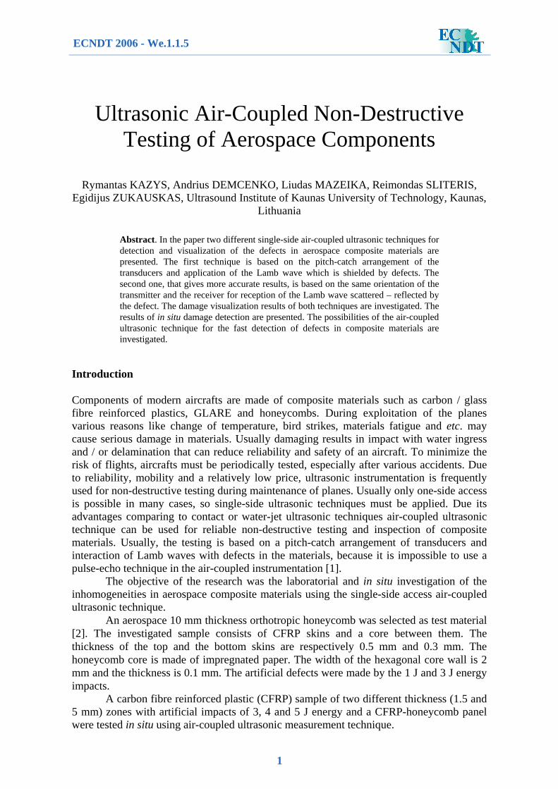
Interaction of Lamb waves with various types of defects was investigated by many researchers [1, 3 - 8]. Summarizing the literature, one can say that the interaction of the Lamb waves with a defect results in the scattering, reflection and mode conversion of the incident Lamb waves. Single-side access air-coupled ultrasonic measurements can be carried out using two different arrangements of transducers: pitch-catch (Fig. 1a) and with the same orientation of transmitter and receiver for reception of scattered-reflected Lamb wave by an inhomogeneity or defect (Fig. 1b) [1, 2, 8, 9].
Fig. 1. The two different transducers arrangements: a) the pitch-catch technique and b) the scattering-
reflection technique, where T is the transmitter, R is the receiver, LW is the Lamb wave, RLW is the reflected Lamb wave, LLW and RLLW are the leaky and the reflected leaky Lamb wave
Measurements, carried out using pitch-catch arrangement of the transducers, are based on shielding of propagating Lamb wave signal by inhomogeneity of material. In this case the Lamb wave propagates between the transmitter and the receiver in material. Therefore, the measurement results depend on the distance between the transducers and the results are not attractive for accurate sizing of inhomogeneities, so a detail analysis of the Lamb wave interaction with inhomogeneity and the Lamb wave leakage over the damage was performed [1, 2]. It was estimated that incident Lamb wave reflects from the end of the defect and strongly leaks over it [1]. More about the wave leakage over the defect can be found in reference [1]. The detected signals by the receiver (Fig. 1b) give more accurate dimensions of the inhomogeneity comparing to the results obtained using pitch-catch arrangement of the transducers. Moreover, the signals are received only over the damaged area and there is not the measurement results dependence on the distance between the transmitter and the receiver.
2. Measurement System
Three pairs of air-coupled unfocused planar transducers, manufactured at the Ultrasound Institute (UI) of Kaunas University of Technology were used in the measurements. Two pairs of rectangular 1-3 piezocomposite transducers, used in laboratory measurements, had resonance frequencies 77 kHz and 210 kHz, the dimensions were 10 × 20 mm. Pair of circular transducers, employed in situ measurements, were of 15 mm diameter and 300 kHz resonance frequency.
The receiver was connected to a 13.4 dB preamplifier. The signals were amplified, digitized and averaged by the air-coupled ultrasonic measurement system controlled by a personal computer via an USB 2.0 interface. The 25 MHz sampling frequency was used in
R
T
Test sample
R
Damaged area LW
a
LLW
T
Test sample Damaged area RLW
b
LW
RLLW
2

all measurements. The averaging minimised a random noise and therefore increased the signal to noise ratio. After averaging the signals were transmitted via USB 2.0 interface and stored in a personal computer for data analysis.
3. Experimental results in laboratory
The measurement results of the 10 mm thickness honeycomb panel using the 77 kHz frequency obtained using pitch- catch arrangement of transducer are presented in Fig. 2. The transmitter was excited by 3 cycles 800 V rectangular burst of 77 kHz. The total gain was 58.4 dB. The signals were averaged from 8 measurements. The transducers were deflected at 24˚ angles and the distance between them was 130 mm. The distance between the honeycomb panel and the transducers was 10 mm. The scanning step was 1 mm in x direction. The results show that damage caused by the week impact (energy 1 J) can be reliably detected by the low frequency (77 kHz) single-side access air-coupled ultrasonic technique. Moreover, the results show that the impact damage reliably can be detected from both sides of the honeycomb. The use of the low frequency ultrasonic transducers (77 kHz) is useful for the fast detection of inhomogeneities in relatively long distances, because the Lamb waves are not as strongly attenuated as at higher frequencies due to viscoelastic properties of composite materials [10]. Therefore, the low frequency transducers are not suitable for accurate visualisation of the damage due to relatively large distance between the transducers, so in this work other measurements were carried out at higher frequencies (210 and 300 kHz). C-can images, formed from measured time of flight data, of 3 J impact damage in 10 mm thickness honeycomb are presented in Fig. 2a. The scanning step was 1 mm in x and y directions during scanning both samples. The defective area can be seen clearly in C-scan image. It is very important that the defect can be detected even from the side opposite to the impact side (Fig.2b). More details about conditions of the experiments on the honeycomb sample can be found in references [1, 2].
Fig. 2. The time of flight C-scan image (a) of the 3 J energy impact damage in 10 mm thickness honeycomb
panel obtained from the impact side (frequency f = 210 kHz) and the B-scan image (b) of 1 J energy impact in the same panel obtained scanning from the opposite side (frequency f = 77 kHz)
Using the pitch-catch arrangement of the transducers as shown in Fig. 1b, the scattered signals were measured over the centres of the damaged area of the honeycomb
Impact position
3
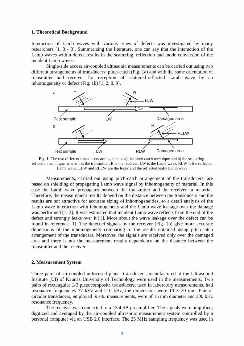
panel. The measurement results are presented as C-can images in Fig. 3. The results show that strong ultrasonic energy leakages over the defects. Due to the interference between the ultrasonic signals the ordinary C-scan images (Fig. 3a) have strongly expressed wavy character, what make analysis of the results more complicated [1, 2]. Below a signal processing technique is presented that enables to create more smooth C-scan images reducing influence of the interference.
It can be noticed that when the transmitter and receiver approaches the defect, the signal reflected by the defect in each next A-scan will be shifted by the value
Lc
dxdt = , (1)
where dx is the scanning step, cL is the Lamb wave propagation velocity. This fact complicates the generation of C-scan images and causes distortion of two types:
1. The “useful” signals are interfering with a parasitic background noise, so the image has a “wavy” character.
2. The position of the signal in the C-scan image does not correspond to the real position of the inhomogeneity.
On the other hand, the quality of the obtained C-scan image can be improved exploiting these features of the acquired signals in the following way:
1. If the delay time of the reflected signal tr is known, the real position of the defect can by estimated by
( ) Lrd ctty ⋅−= 0 , (2) where t0 is the systematic delay in air, matching layers, electronics and can be estimated during calibration.
2. In each A-scan acquired approaching the defect the reflected signal corresponds to the same defect and differs only by the delay time (the known value) and the amplitude (due to attenuation). So integration of all these signal with a corresponding shift in the time domain will enable to increase not only the signal to noise ratio but also the ratio of the “useful” signal with respect to other signals not related to the reflection from the defect (similar to the SAFT approach).
Therefore, the signal processing was performed in the next steps: 1. Estimation of the Lamb wave velocity cL is given by
L
L dtdxc = , (3)
where dx is the scanning step, NB is the number of the signals in the B-scan image and dtL is given as
⎥⎥⎦
⎤
⎢⎢⎣
⎡⎟⎟⎠
⎞⎜⎜⎝
⎛ ⋅−= ∑
=
B
y
yxm
N
k m
ykkdtL dt
dxktudt
1,maxarg . (4)
2. The integrated single signal is created from all B-scan image signals according to
∑=
Σ ⎟⎟⎠
⎞⎜⎜⎝
⎛ ⋅−=
B
yyxx
N
k m
ykkk dt
dyktutu
1,)( . (5)
3. The virtual C-scan image is created from the set of the signals, setting the scale along the y axis according to
Lcty ⋅= . (6) In general, this is a B-scan image, but with a view from the top. In the images the x
axis corresponds to the scanning position, and the y axis in the image corresponds to the delay time or the distance according to the position y = y0. It can be seen that C-scan image after processing (Fig. 3b) is clearer and have better contrast.
4
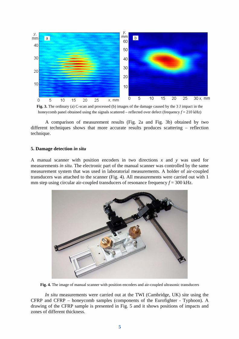
Fig. 3. The ordinary (a) C-scan and processed (b) images of the damage caused by the 3 J impact in the honeycomb panel obtained using the signals scattered – reflected over defect (frequency f = 210 kHz)
A comparison of measurement results (Fig. 2a and Fig. 3b) obtained by two different techniques shows that more accurate results produces scattering – reflection technique.
5. Damage detection in situ
A manual scanner with position encoders in two directions x and y was used for measurements in situ. The electronic part of the manual scanner was controlled by the same measurement system that was used in laboratorial measurements. A holder of air-coupled transducers was attached to the scanner (Fig. 4). All measurements were carried out with 1 mm step using circular air-coupled transducers of resonance frequency f = 300 kHz.
Fig. 4. The image of manual scanner with position encoders and air-coupled ultrasonic transducers
In situ measurements were carried out at the TWI (Cambridge, UK) site using the CFRP and CFRP – honeycomb samples (components of the Eurofighter - Typhoon). A drawing of the CFRP sample is presented in Fig. 5 and it shows positions of impacts and zones of different thickness.
5

Before scanning the acoustic unit with air-coupled ultrasonic transducers was attached to the 5 mm thickness sample zone. After this, the excitation and reception angles of the transducers were manually adjusted until the amplitude of the received leaky ultrasonic signal was the highest. Then the sample manually was scanned over the impacts along the x axis. The measurement results are presented in Fig. 6. The results show that impact of 5 J energy is seen the best in the B-scan image and the impacts of 3 and 4 J are not so clear (Fig. 6). Also it is seen that the amplitude of the ultrasonic signals is low. This can be explained by different Lamb wave velocities at sample zones of the different thickness. Due to the thickness difference, the excitation and reception angles of the Lamb wave signals become non-optimal and therefore the amplitude of the signals drops down [1]. A drawing of the CFRP – honeycomb sample (6376/35%/268/HTS) is presented in Fig. 7 and it shows scanned area with defects. The exact distribution of the defects was disclosed only when the measurements have been finished. Due to the large dimension of the sample and the limitations of the manual scanner only denoted zone (Fig. 7) was scanned. Obtained C-scan image is presented in Fig. 8. All four defect presented in the scanned area clearly can be seen in the obtained image, even those which were scanned partially (were situated on the boundary of scanning region).
Fig. 5. The drawing of the measured sample in situ (CFRP sample)
Fig. 6. The B-scan image of the measured CFRP sample in situ. The central frequency f = 300 kHz
3 J 5 J 4 J
650 mm
210 mm
195 mm 195 mm 200 mm
120 mm 120 mm
29 mm
100
mm
220
mm
30
mm
5 mm 1.5 mm
29 mm
3 J 5 J 4 J
6

Fig. 7. The drawing of the measured sample in situ (CFRP – honeycomb sample)
Fig. 8. The amplitude C-scan image of the measured CFRP – honeycomb sample in situ. The central frequency f = 300 kHz
55 mm 207 mm 302 mm
450 mm
50x50 mm 25x25 mm 15x15 mm 10x10 mm
80 m
m
230
mm
35
0 m
m
Crushed core
Cut out
Scanned area
7

Conclusions
Different types of aerospace materials such as CFRP and honeycomb have been tested by two different single-side access air-coupled ultrasonic techniques. Both single-side access air-coupled ultrasonic techniques have shown high sensitivity to various types of defects in the aerospace composite materials. It has been shown that scattering – reflection technique is more accurate and is more suitable for sizing of defects than the technique with pitch-catch arrangement of the transducers. The signal processing technique have been developed that essentially reduces the influence of the interference of the ultrasonic signals and enables to obtain C scan images having better resolution and contrast.
Air-coupled ultrasonic measurements have been carried out in situ. The in situ measurements demonstrated high reliability of the air-coupled technique for defect detection in airspace composite materials.
Acknowledgment
The authors thank Algirdas Voleisis for design and manufacturing of the rectangular shape air-coupled ultrasonic transducers.
The authors wish to thank to TWI centre for support of test samples for measurements in situ.
The part of this work was sponsored by the European Union through the Aeronautics programme under the Framework-5 NANOSCAN project.
References
[1] A.Demcenko, E. Zukauskas, R. Kazys, A. Voleisis: Interaction of the A0 Lamb wave mode with a delamination type defect in GLARE3-3/2 composite material, Acta Acustica united with Acustica, in press, 2006.
[2] R. Kazys, A. Demcenko, E. Zukauskas, L. Mazeika: Air-coupled ultrasonic investigation of multi-layered composite materials, Ultrasonics, in press, 2006.
[3] D. N. Alleyne, P. Cawley: The interaction of Lamb waves with defects. IEEE Trans. Ultrason., Ferroelect., Freq. Contr. 39 (1992) 381-396.
[4] N. Guo, P. Cawley: The interaction of Lamb waves with delaminations in composite laminates. J. Acoust. Soc. Am. 94 (1993) 2240-2246.
[5] Y. Cho, D. D. Hongerholt, J. L. Rose: Lamb wave scattering analysis for reflector characterization. IEEE Trans. Ultrason., Ferroelect., Freq. Contr. 44 (1997) 44-52.
[6] Y. Cho: Estimation of ultrasonic guided wave mode conversion in a plate with thickness variation. IEEE Trans. Ultrason., Ferroelect., Freq. Contr. 47 (2000) 591-603.
[7] T. Hayashi, K. Kawashima: Multiple reflections of Lamb waves at delamination. Ultrasonics 40 (2002) 193-197.
[8] M. Castaings, P. Cawley: The generation, propagation, and detection of Lamb waves in plates using air-coupled ultrasonic transducers, J. Acoust. Soc. Am. 100 (5) (1996) 3070-3077.
[9] D.W. Schindel, D.S. Forsyth, D.A. Hutchins, A. Fahr, “Air-coupled ultrasonic NDE of bonded aluminum lap joints”, Ultrasonics, 35, (1997) 1-6.
[10] M. Castaings, B. Hosten, T. Kundu: Inversion of ultrasonic, plane-wave transmission data in composite plates to infer viscoelastic material properties. NDT&E Int. 33 (2000) 377-392.
8