Embed Size (px)
Citation preview
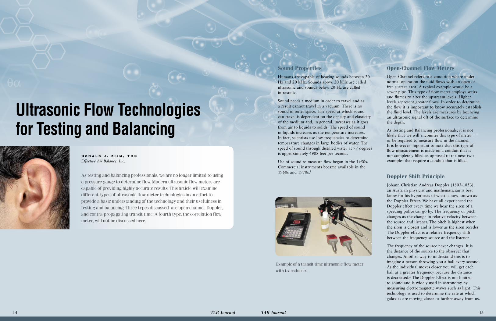
D o n a l d J . Z i j m , T B EEffective Air Balance, Inc.
Ultrasonic Flow Technologies for Testing and Balancing
Sound Properties
Humans are capable of hearing sounds between 20 Hz and 20 kHz. Sounds above 20 kHz are called ultrasonic and sounds below 20 Hz are called infrasonic.
Sound needs a medium in order to travel and as a result cannot travel in a vacuum. There is no sound in outer space. The speed at which sound can travel is dependent on the density and elasticity of the medium and, in general, increases as it goes from air to liquids to solids. The speed of sound in liquids increases as the temperature increases. In fact, scientists use low frequencies to determine temperature changes in large bodies of water. The speed of sound through distilled water at 77 degrees is approximately 4908 feet per second.
Use of sound to measure flow began in the 1950s. Commercial instruments became available in the 1960s and 1970s.1
Open-Channel Flow MetersOpen-Channel refers to a condition where under normal operation the fluid flows with an open or free surface area. A typical example would be a sewer pipe. This type of flow meter employs weirs and flumes to alter the upstream levels. Higher levels represent greater flows. In order to determine the flow it is important to know accurately establish the fluid level. The levels are measures by bouncing an ultrasonic signal off of the surface to determine the depth.
As Testing and Balancing professionals, it is not likely that we will encounter this type of meter or be required to measure flow in the manner. It is however important to note that this type of flow measurement is made on a conduit that is not completely filled as opposed to the next two examples that require a conduit that is filled.
Doppler Shift Principle
Johann Christian Andreas Doppler (1803-1853), an Austrian physicist and mathematician is best know for his hypothesis of what is now known as the Doppler Effect. We have all experienced the Doppler effect every time we hear the siren of a speeding police car go by. The frequency or pitch changes as the change in relative velocity between the source and listener. The pitch is highest when the siren is closest and is lower as the siren recedes. The Doppler effect is a relative frequency shift between the frequency source and the listener.
The frequency of the source never changes. It is the distance of the source to the observer that changes. Another way to understand this is to imagine a person throwing you a ball every second. As the individual moves closer you will get each ball at a greater frequency because the distance is decreased.2 The Doppler Effect is not limited to sound and is widely used in astronomy by measuring electromagnetic waves such as light. This technology is used to determine the rate at which galaxies are moving closer or farther away from us.
14 TAB Journal 15TAB Journal

Doppler Flow Meters
Two technologies use the Doppler effect to measure fluid velocity. The first is a Laser Doppler Velocimeter (LDV). The second, and more commonly know is the Acoustic Doppler Velocimeter (ADV).
The Doppler Velocimeter sends a signal through the pipe at a given frequency. The signal reflects off of particulates in the fluid back to the transducer (see figure 1). The difference between the frequency sent and the frequency received is directly proportional to the flow.
The accuracy and usability of the Doppler Velocimeter is dependent on several factors. The primary factors are the quantity of particles or air bubbles in the fluid, the size of the particles and or air bubbles, the distribution of these particles, the type of transducer, the ability of the signal to penetrate the pipe and the location of the reading.
Given this information, it becomes obvious that a Doppler Flow meter cannot be used with clean liquids. In fact most meters require that the particulates in the fluid represent 25 ppm and that these particles have a minimum size of 30 microns.
Transit-Time Flow Meters
The principal behind contra-propagating or transit-time ultrasonic flow meters is quite simple to understand. Two piezoelectric transducers are placed on a pipe as shown in Figure 2, a double traverse, or Figure 3, a single traverse. Each transducer is capable of sending and receiving a signal. The signal from the transducer that is upstream travels with the direction of fluid flow. The signal from the transducer that is located downstream travels against the flow. The result is that is takes longer for the signal from the downstream transducer to reach the upstream transducer than it takes the signal from the upstream transducer to reach the downstream transducer. The difference in “time-of-flight” is measured and is directly related to the velocity of the fluid. It is important to note that the “time-of-flight” is an average.
The meter must be programmed with site information prior to mounting the transducers. Information such as the pipe material, outside diameter, wall thickness, and fluid type must be entered into the meter’s memory. The meter will then provide the distance that the transducers must be spaced. This is a fairly simple process with the use of a ruled clamping fixture.
Similar to the Doppler Meter, there are factors that affect accuracy. Turbulence, for example, has an impact on the accuracy of ultrasonic flow readings. As the pulse travels through the pipe, the signal is dragged different amounts depending on the velocity at a given point.
“Sound propagation through a random media is an important and much studied subject. It is understood that turbulence affects sound propagation through fluids, and, has been discovered, the effect must be quantified to determine the behavior of ultrasonic
Signal Sent
Signal Received
Particulates
Piezoelectric
Transducers
Double Traverse
Flow
Single Traverse
Flow
Ultrasonic Signal
Figure 2
Signal Sent
Signal Received
Particulates
Piezoelectric
Transducers
Double Traverse
Flow
Single Traverse
Flow
Ultrasonic Signal
Figure 3
flowmeters. One strategy of investigation is to follow the sound path through a turbulent flow field. Rayleigh, who developed the generalized Ray Trace method for following a sound wave in a fluid was among the first people to study the effect of turbulence on sound propagation.”1
The Reynolds number is used to determine if a flow will be laminar or turbulent. Some of the more sophisticated ultrasonic flow meters are capable of providing the Reynolds number while taking a Traverse of the pipe flow. In general, the lower Reynolds numbers indicate laminar flow and the higher numbers relate to turbulent flow. A Reynolds number of 2300 for circular pipes is considered to be a critical point.2
The location of the Transducers will go a long way to help prevent turbulent readings. The distance before and after the location of the transducer is an important consideration when making an ultrasonic flow reading. “However, if the measurement location is not in a long straight pipe, but instead is located downstream of any number of piping configurations, more paths are needed to reduce the uncertainty of the assumed velocity profile in the pipe. If a swirling flow is suspected, it may be necessary to place ultrasound paths in a configuration at each chordal location to account for the swirl.”1 Most meters recommend 10 pipe diameters on the upstream side and 5 pipe diameters downstream. On a horizontal pipe the transducers should be located on the side of the pipe. If there is air in the pipe it will tend to collect at the top of the pipe and cause erroneous readings. In addition, many meters do not recommend reading flow on a vertical pipe when the flow is traveling down the pipe.
In sum, ultrasonic technologies have been around long enough to now have practical application in Testing and Balancing. As we have seen, using a Doppler ultrasonic flow meter requires that the fluid being measured has particulates. Transit Time flow meters are the most practical in our industry since we frequently measure clean fluids. In either case, care must be taken when preparing for and evaluating a reading.
Sources: 1Ultrasonic Beam Propagation in Turbulent Flow by Francis J. Weber, Jr. 2Wikipedia. 3Simulations of Ultrasonic Transit Time in a Fully Developed Turbulent Flow using a Ray-Tracing Method Dr. Pamela I. Moore, Dr. Aaron N. Johnson, Dr. Pedro I. Espina
Signal Sent
Signal Received
Particulates
Piezoelectric
Transducers
Double Traverse
Flow
Single Traverse
Flow
Ultrasonic Signal
Figure 1
16 TAB Journal 17TAB Journal