Embed Size (px)
Citation preview
1
ultra-wave™
Ultrasonic Level
DetectionTechnology

2
Definitions
• Vacuum - The absence of molecules in an area
• Ultrasonic -Concerned with ‘sound’ having a frequency ≥20,000 Hz
• Sound - The propagation of pressure waves through air or other media
• Medium - A material through which sound can travel

3
Definitions
• Transducer - Any device that converts energy from one form to another.
• Range - The measured distance between a reference point and another point in space.
• Ranging-Measurement of the time from the transmission of a sound pulse to the reception of its echo.

4
Definitions
• Signal-to-Noise Ratio (S/N) - Ratio of signal amplitude to noise amplitude, usually expressed in decibels.
Blind Space - The amount of time required for the transducer vibration to decay to a level such that ultrasonic measurement of distance is possible
5
Definitions
• Decibels - The measure of the intensity of sound.– 0 dB - The arbitrary value assigned the faintest
audible sound that the human ear can hear.– 1 dB - The smallest difference between sounds
that is humanly detectable.– 120 dB - The loudest sound that a human ear
can tolerate.
6
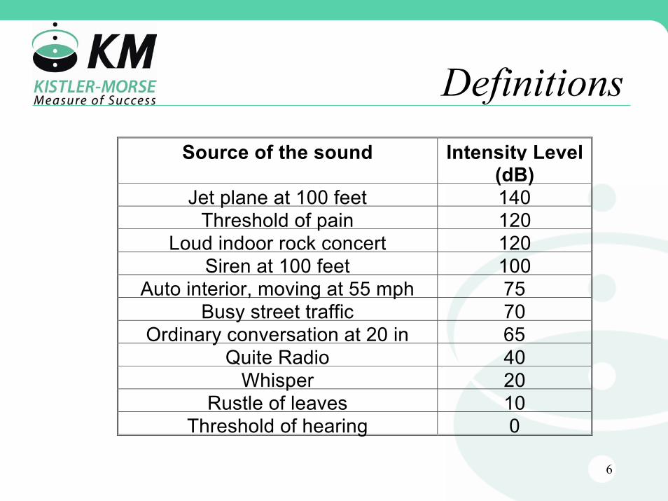
DefinitionsSource of the sound Intensity Level
(dB)Jet plane at 100 feet 140
Threshold of pain 120Loud indoor rock concert 120
Siren at 100 feet 100Auto interior, moving at 55 mph 75
Busy street traffic 70Ordinary conversation at 20 in 65
Quite Radio 40Whisper 20
Rustle of leaves 10Threshold of hearing 0
7
Definitions
• Reflected - Energy is reflected or returned into the medium through which it has traveled when a sound wave encounters an interface between media of differing properties.
• Interface - A change in a transmission medium which affects the sound energy
• Target - the surface (interface) we wish to measure.
• Level - the amount of material in a vessel.
8
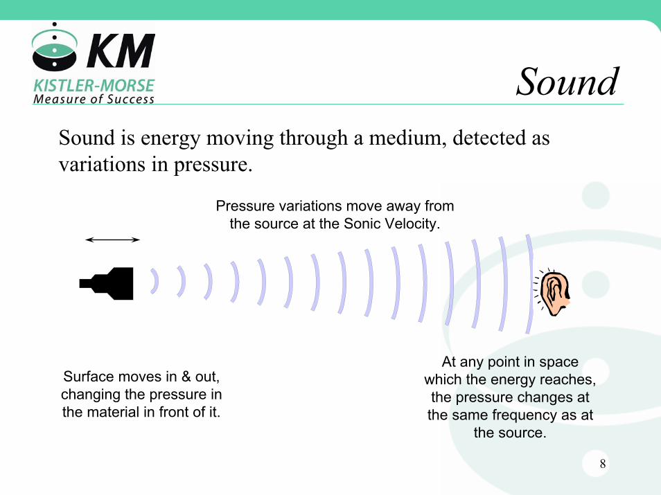
SoundSound is energy moving through a medium, detected as variations in pressure.
Pressure variations move away from the source at the Sonic Velocity.
At any point in space which the energy reaches, the pressure changes at the same frequency as at
the source.
Surface moves in & out, changing the pressure in the material in front of it.

9
Attributes of Sound
• Velocity - the speed at which sound travels through a particular medium (feet/min, MPH, etc.)
• Frequency - the rate at which the pressurevariations of sound occur (Cycles/second = Hertz)
• Intensity - the difference in pressure between minimum and maximum (typically measured in decibels greater or less than some reference value)

10
Speed of Sound
• 1126 Feet per Second– @ 20°C Temperature– @ 50% Humidity– @ 1 Atmosphere

11
Speed of Sound13.6 inches (34.54 cm)
Air - 1126 ft per second @68°F (343.2 meters per second @20°C)
13.0 inches (33.02 cm)
Air - 1089 ft per second @32°F (331.9 meters per second @0°C)
10.2 inches (25.91 cm)
CO - 850 ft per second @68°F (259.1 meters per second @20°C)
5.7 inches (14.48 cm)
Carbon Tetrachloride Vapor - 475 ft per second @189°F (144.8 meters per second @87.2°C)
2

12
Basic EquationDistance = Velocity x Time
Distance = 1126 ft/sec x 9 sec
Distance = 10,134 ft
Sourceof
SoundSoundSensor
Distance = Velocity x Time

13
Basic Equation Factors
• Distance - The distance from the source of sound to the sensor
• Velocity - The speed at which sound moves through the medium between the source and the sensor
• Time - The amount of time needed for the sound to move from the source to the sensor
14
Basic Equation Example
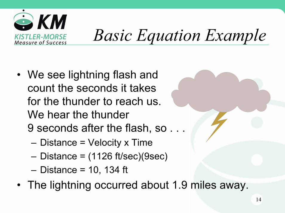
• We see lightning flash and count the seconds it takes for the thunder to reach us.We hear the thunder 9 seconds after the flash, so . . .– Distance = Velocity x Time– Distance = (1126 ft/sec)(9sec)– Distance = 10, 134 ft
• The lightning occurred about 1.9 miles away.

15
Range Equation R = Range
V= Velocity
T = Time2VTR =
TransducerSource & Receiver Target
Distance =Velocity x Time2
Range = (1126 ft./sec) (50 msec.) = 28.15 ft.2
16
Range Equation Factors
• RANGE - The distance from the source of a signal to a target and back
• VELOCITY - The speed at which sound moves through the medium between the reference position and the target
• TIME - The amount of time needed for the sound to move from the Reference Position to the Target and back.
17
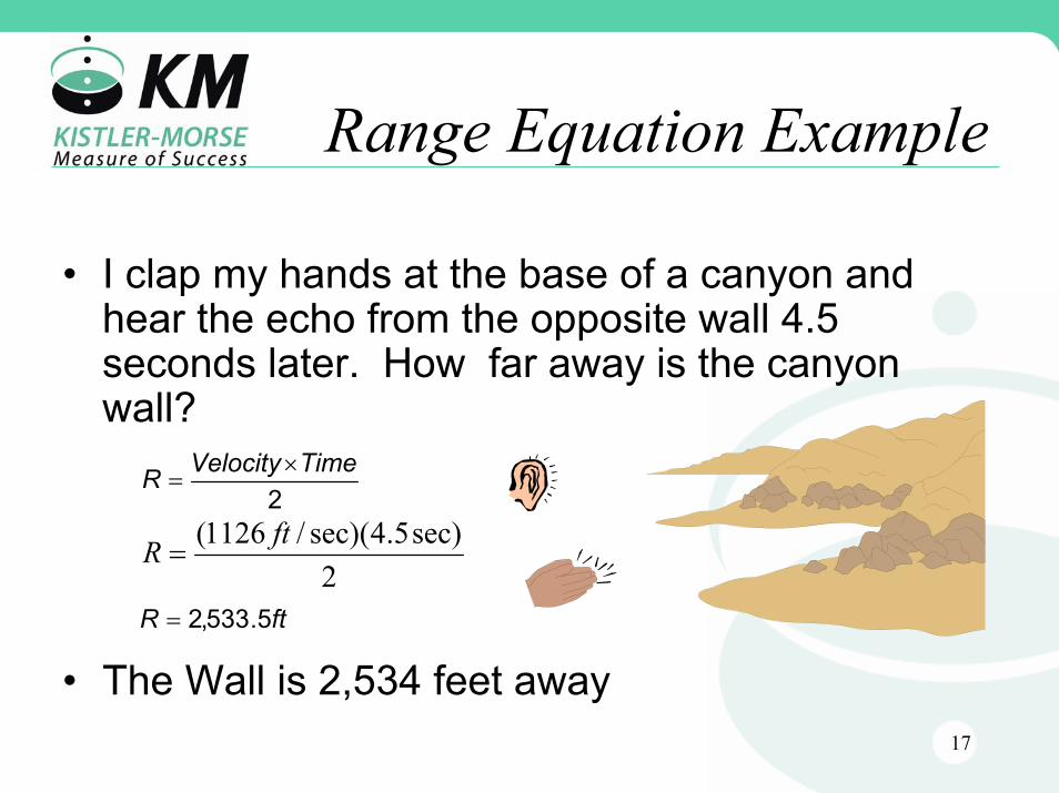
Range Equation Example
• I clap my hands at the base of a canyon and hear the echo from the opposite wall 4.5 seconds later. How far away is the canyon wall?
• The Wall is 2,534 feet away
2TimeVelocityR ×
=
2sec)5.4sec)(/1126( ftR =
ftR 5.533,2=

18
Energy TransferRequirements
• An acoustic pulse strong enough to overcome attenuation over the desired range
• A density change between the target material and the surrounding atmosphere
• An Echo which returns along the same path as the transmitted signal.
• An acceptable level for the signal-to-noise ratio
19
Causes of Energy Losses & Errors
• Vessel Filling• Angle of Reflection• Material Angle• Material Properties• Signal-To-Noise
Ratio
• Distance• Temperature • Humidity• Atmospheric Density• Dust
20
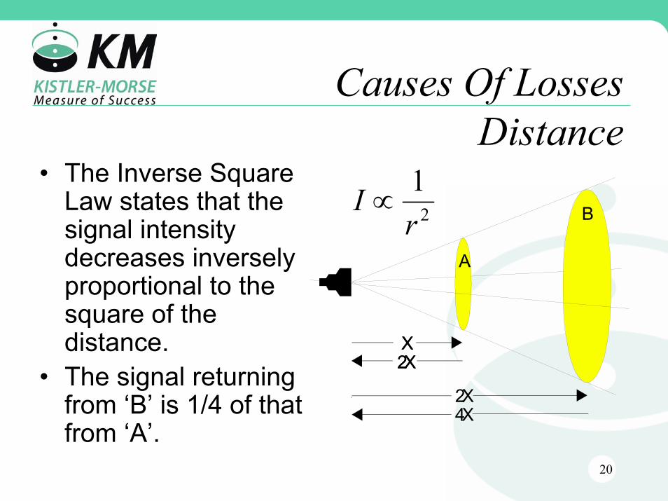
Causes Of LossesDistance
• The Inverse Square Law states that the signal intensity decreases inversely proportional to the square of the distance.
• The signal returning from ‘B’ is 1/4 of that from ‘A’.
2
1r
I ∝
X2XX2X
2X4X
B
A
21
Causes of ErrorTemperature
• The speed of sound increases with increasing temperature at the rate of .17%/C° (≈1% for each 10 F°)

22
Causes of ErrorHumidity
• An increase in relative humidity from 0% to 100% increases the speed of sound 0.44%
23
Causes of ErrorsDensity
• An increase in the atmospheric density decreases the speed of sound.
24
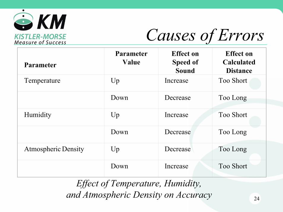
Causes of ErrorsParameter
Parameter Value
Effect on Speed of Sound
Effect on Calculated Distance
Temperature Up Increase Too Short
Down Decrease Too Long
Humidity Up Increase Too Short
Down Decrease Too Long
Atmospheric Density Up Decrease Too Long
Down Increase Too Short
Effect of Temperature, Humidity, and Atmospheric Density on Accuracy
25
Causes of LossesDust
• Dust has two main effects:– Absorbs acoustic energy– Decreases the apparent roughness of the
surface of the target material
26
Causes of LossesVessel Filling
• Material passing through an acoustic beam will reflect or disperse the acoustic energy.
27
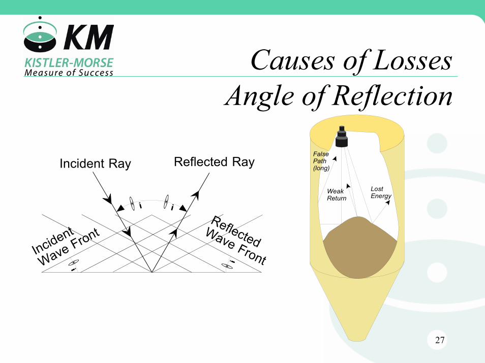
Causes of LossesAngle of Reflection
FalsePath(long)
LostEnergy
WeakReturnΘ i
Θi Θ i
Θ i
Incident Ray
ReflectedWave Front
Reflected Ray
Incident
Wave Front
28
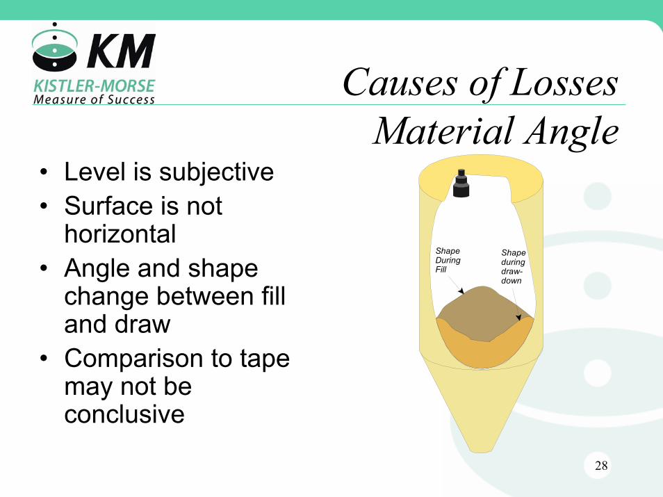
Causes of LossesMaterial Angle
• Level is subjective• Surface is not
horizontal• Angle and shape
change between fill and draw
• Comparison to tape may not be conclusive
ShapeDuringFill
Shapeduringdraw-down

29
Causes of LossesMaterial Properties
• Acoustic Reflection Coefficient (ARC) is a function of:– Wavelength of the acoustic wave– Particle size and shape of the target material– Angle at which the acoustic wave strikes the
target material.
30
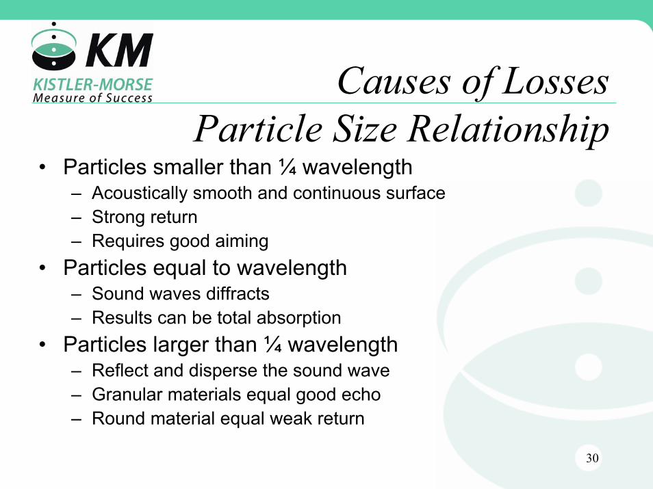
Causes of LossesParticle Size Relationship
• Particles smaller than ¼ wavelength– Acoustically smooth and continuous surface– Strong return– Requires good aiming
• Particles equal to wavelength– Sound waves diffracts– Results can be total absorption
• Particles larger than ¼ wavelength– Reflect and disperse the sound wave– Granular materials equal good echo– Round material equal weak return
31
Causes of LossesSignal-To-Noise Ratio
• A ratio of the strength of the received signal to the strength of the background noise.
This ratio must be greater that 1
32
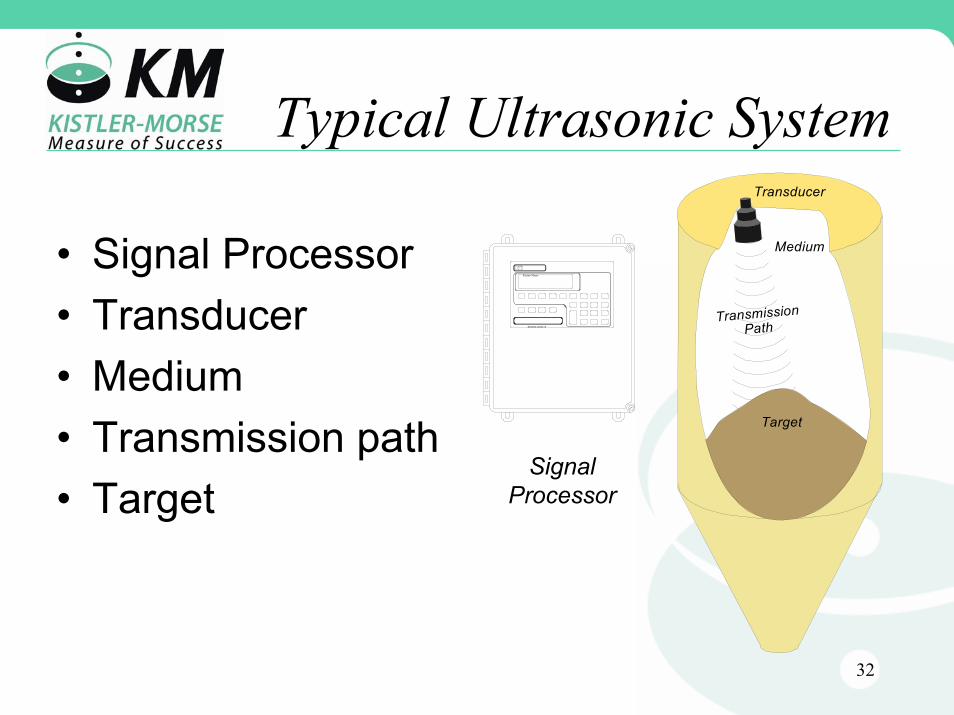
Typical Ultrasonic System
Medium
TransmissionPath
Target
Transducer
• Signal Processor• Transducer• Medium• Transmission path• Target
SONOLOGIC II
Kistler-Morse
Signal Processor
33
The Signal Processor
• Scales the range signal to engineering units
• Provides for operator access
• Provides external output signals
• Provides the electrical energy for the transducer
• Controls the timing of events
• Performs the range calculation

34
The Transducer
• Converts electrical energy to acoustic energy
• Converts acoustic energy to electrical energy
• Provides directional control of energy

35
TransducerAttributes
• Frequency• Efficiency• Dispersion Angle

36
TransducerFrequency
• Larger transducers– resonate at lower frequencies– are useable at longer ranges– greater blind space due to larger mass
• Smaller transducers– resonate at higher frequencies– are useable on shorter ranges– smaller blind space due to less mass

37
TransducerEfficiency
Efficiency = Power InPower Out
• Higher efficiency results in higher effective signal strength
• Lower efficiency can usually be overcome by increased power
38
TransducerEfficiency
• Factor That Affect – Mechanical construction– Frequency– Temperature– Pressure
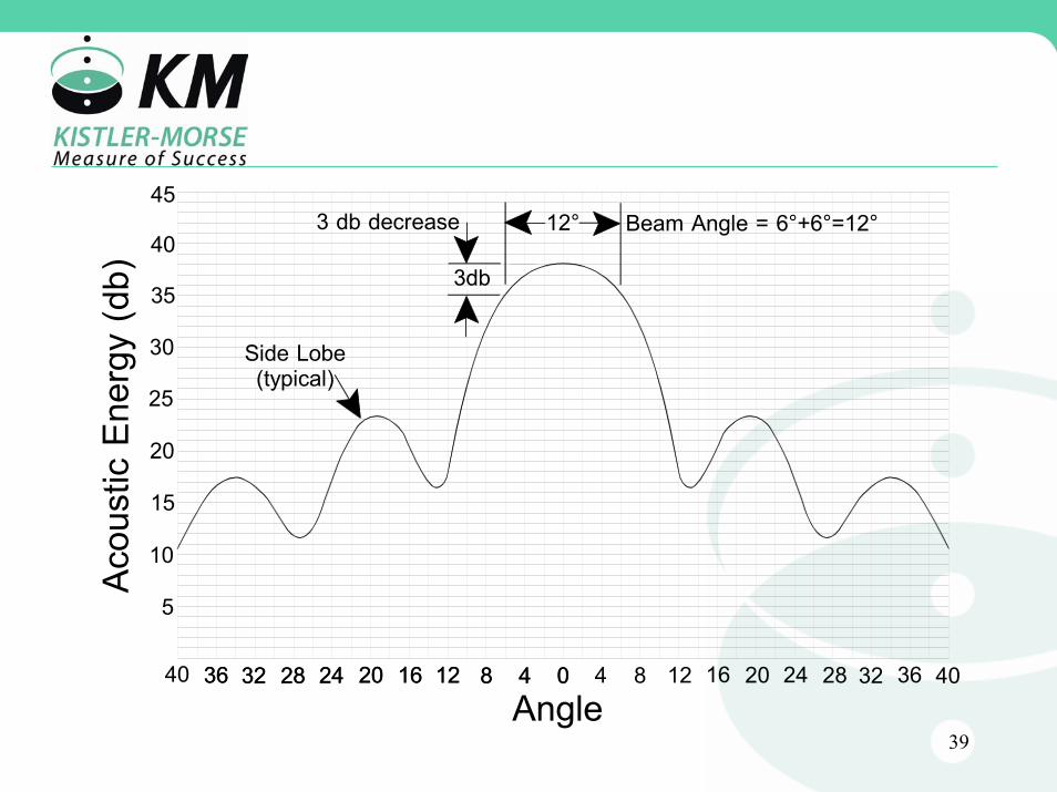
39
5
10
15
20
25
30
35
40
048121624 20283236 4 8 12 16 2420 28 32 36 40048121624 2028323640
453 db decrease Beam Angle = 6°+6°=12°12°
3db
Side Lobe(typical)
Angle
Acou
stic
Ener
gy(d
b)
40
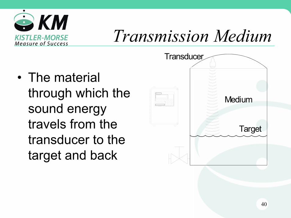
Transmission MediumTransducer
Target
MediumSONOLOGIC II
Kistler-Morse
• The material through which the sound energy travels from the transducer to the target and back
41
Sonic Energy Path
• Should be clear of obstacles:– Framing or other vessel support hardware– Suspended solids or liquids in the medium– Material delivery and discharge systems– sensor probes– Ladders– Bolt heads, rebar, welds, joint seams, etc.
42
Acoustic Energy Striking An Interface Is
• Absorbed– and converted to heat
• Transmitted– through another medium
• Reflected– Back to the transducer

43
A Suitable Target Surface Is Affected By
• Size and shape of the particles which make up the material. Angular shapes produce stronger echoes
• The angle of repose of the material• The moisture content of the material
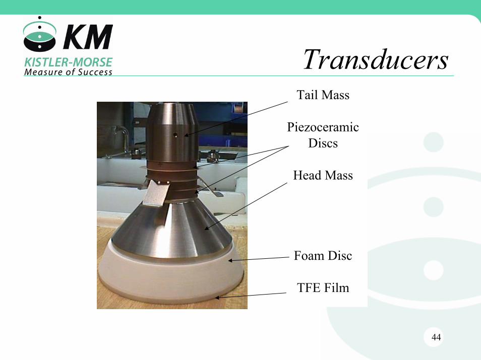
44
TransducersTail Mass
PiezoceramicDiscs
Head Mass
Foam Disc
TFE Film
45
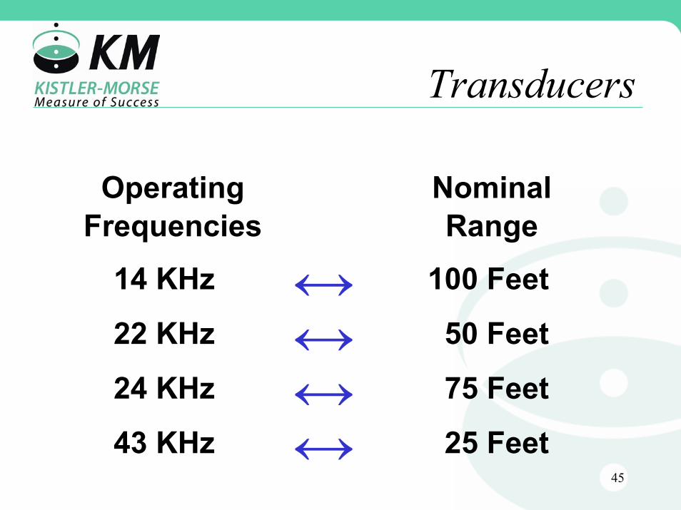
Transducers
NominalRange
Operating Frequencies
100 Feet
50 Feet
75 Feet
25 Feet
14 KHz
22 KHz
24 KHz
43 KHz
46
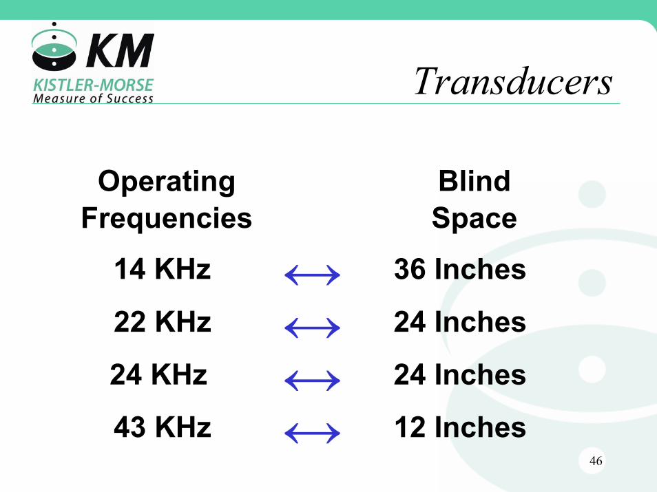
Transducers
Operating Frequencies
BlindSpace
14 KHz
22 KHz
24 KHz
43 KHz
36 Inches
24 Inches
24 Inches
12 Inches
47
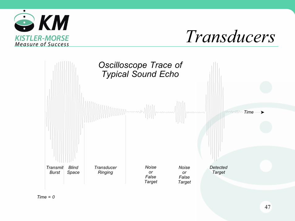
Transducers
Noiseor
FalseTarget
DetectedTarget
Noiseor
FalseTarget
TransducerRinging
TransmitBurst
BlindSpace
Oscilloscope Trace ofTypical Sound Echo
Time = 0
Time

48
EnclosureType
TemperatureLimit
Stainless Steel
CPVC
PVC
Flanged
230 ºF
180 ºF
160 ºF
160 ºF
49
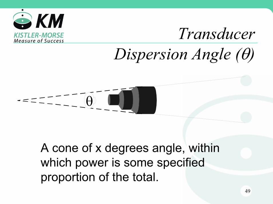
TransducerDispersion Angle (θ)
θ
A cone of x degrees angle, within which power is some specified proportion of the total.

50
Transducer Angle Example
• Dispersion angle has limited use in predicting performance.
• Smaller angles are usually more desirable
51
Selecting a Transducer
• Should have a range greater than or equal to the height of the vessel
• Must be checked for compatibility with the material in the vessel
• Must be selected for the range of temperature that it will encounter
52
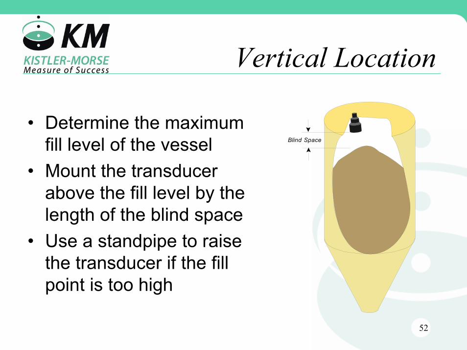
Vertical Location
Blind Space
• Determine the maximum fill level of the vessel
• Mount the transducer above the fill level by the length of the blind space
• Use a standpipe to raise the transducer if the fill point is too high

53
Horizontal LocationHorizontalLocation
• Mount the transducer away from the wall
• Mount the transducer as far away from the filling point as possible to minimize the amount of material which flows through the acoustic beam
54
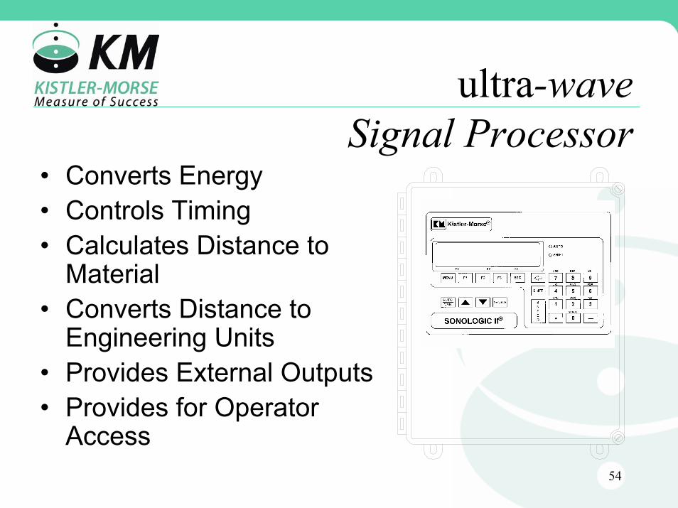
ultra-waveSignal Processor
• Converts Energy• Controls Timing• Calculates Distance to
Material• Converts Distance to
Engineering Units• Provides External Outputs• Provides for Operator
Access
SONOLOGIC II
Kistler-Morse

55
ultra-wave Applications
• Level Measurement– 1 to 16 Continuous Level Applications
• Differential Level Measurement– 1 to 8 DLD Applications
• Open Channel Flow Measurement– 1 to 4 OCM Applications
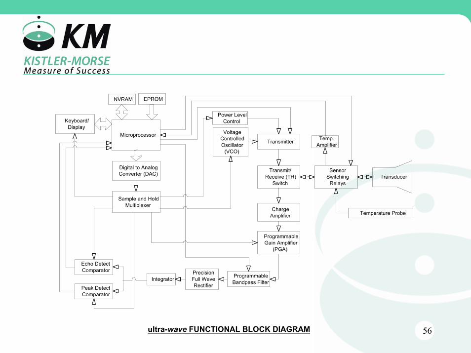
56
Microprocessor
NVRAM EPROM
PrecisionFull WaveRectifier
Integrator
Echo DetectComparator
Peak DetectComparator
ProgrammableBandpass Filter
ProgrammableGain Amplifier
(PGA)
Digital to AnalogConverter (DAC)
Sample and HoldMultiplexer
ChargeAmplifier
Transmit/Receive (TR)
Switch
Transmitter
Power LevelControl
VoltageControlledOscillator
(VCO)
Keyboard/Display
SensorSwitching
Relays
Temperature Probe
Temp.Amplifier
ultra-wave FUNCTIONAL BLOCK DIAGRAM
Transducer

57
ultra-wave System Configuration