Embed Size (px)
Citation preview
1
Ultrasonic Techniques Based Inversion of Elastic Properties for a
Single Lamina in Composites Laminates
Jinling ZHAO, Jinhao QIU, Hongli JI
State Key Laboratory of Mechanics and Control of Mechanical Structures,
Nanjing University of Aeronautics and Astronautics,
Nanjing, Jiangsu 210016, China
[email protected] (Jinhao Qiu)
Abstract
A composite laminate is generally considered consisting of a series of laminae having
the same elastic constants but different material orientations, and each lamina can be
thought of as a transversely isotropic material. With known stacking sequences, this
research proposed a Lamb wave based methodology to reconstruct the stiffness
coefficients of each lamina in composite laminates. Genetic algorithms (GAs) are
used to implement the inversion by minimizing the error between the experimentally
measured Lamb wave phase velocities and the theoretically calculated ones. A laser
generation based imaging (LGBI) system is introduced to accurately measure the
phase velocities of the propagating Lamb waves. Theoretically, a semi-analytical
finite element (SAFE) method is employed to calculate the dispersion curves. In this
research, a unidirectional carbon fibre reinforced plastic (CFRP) composite is
studied with regard to elastic properties evaluation. The reconstructed parameters
are compared with the real material properties.
Keywords: Lamb wave, Elastic properties, Composites
1. INTRODUCTION
Carbon fibre reinforced plastic (CFPR) material is increasingly used in advanced
engineering fields, especially for aerospace applications, due to its high
strength-to-weight ratio, stiffness-to-weight ratio and design flexibility. The elastic
parameters of CFRP are required to conduct theoretical analysis, corresponding
mechanics researches and laminate structure design. Also, tracking elastic properties
variation enables online evaluation of CFRP fatigue damages [1, 2] and in-situ
prediction of the structures remaining life, due to the stiffness degradation
phenomenon during composites fatigue process.
Ultrasound techniques to measure solid stiffness is well established for isotropic
materials. Using bulk wave methods, Young’s modulus and Poisson’s ratio can be
determined by measuring longitudinal and shear waves speeds. This method has
several limitations, such as the requirement of high-frequency equipment and separate
samples. Lamb waves method [3], on the other hand, enables in-situ evaluation of
structure damages. Rogers [4] measured Lamb wave velocities and inversed the
elastic properties of several isotropic materials.
Anisotropic materials, including CFRP of interest, have at least five independent
stiffness coefficients, which complicates the propagation waves characteristics and
thus the material properties determination. Wu et al. [5] evaluated the five stiffness
coefficients of a unidirectional plate using combined bulk wave method and Lamb
wave approach. Vishnuvardhan et al. [6] used a structural health monitoring array to
8th European Workshop On Structural Health Monitoring (EWSHM 2016), 5-8 July 2016, Spain, Bilbao
www.ndt.net/app.EWSHM2016M
ore
info
abo
ut th
is a
rtic
le: h
ttp://
ww
w.n
dt.n
et/?
id=
1992
1
2
measure the A0 and S0 modes group velocities, and inversed the velocities to obtain
the material properties of orthotropic plates. The authors considered that the measured
group velocities are equal to the phase velocities, which are not the case for Lamb
wave modes. Ong et al. [7] determined the elastic properties of woven composite
panels through comparison of the wide-frequency-band simulated dispersion curves
and the experimental ones. The error between the reconstructed parameters and the
real properties are significant. Zhao et al. [8] reconstructed the equivalent-single-layer
elastic properties of CFRP by inversing the Lamb wave phase velocities measured by
a laser generation based imaging (LGBI) system. The authors verified the results
indirectly due to the lack of real material properties.
The equivalent–single-layer assumption is unfeasible for high-frequency Lamb
wave modeling, since the wave structure varies remarkably along the thickness
direction [9]. This paper intends to evaluate the elastic properties of each layer in
composite laminates, rather than equivalent elastic constants. Assuming that the
consisting layers in the laminate are of same material properties (transversely
isotropic material) but different material orientations, the five independent stiffness
coefficients to be determined are respectively C11, C12, C22, C23 and C55, where axis 1
indicates the local fibre direction and axis 3 denotes the thickness direction.
This paper is organized as following. The theoretical background to solve the
forward problem is introduced in section 2. Then the sensitivity analysis of wave
speed to material properties is conducted, followed by the description of the inversion
method, i.e., genetic algorithms. The next section described the laser based ultrasound
experimental setup and the dispersion curves measurement. Reconstruction and
validation of material properties for a unidirectional CFRP composite are presented in
the last section.
2. SEMI-ANALYTICAL FINITE ELEMENT (SAFE) METHOD
Theoretical modeling of Lamb waves in composite laminates are well developed
[9-12]. The exact solutions can be obtained using three dimensional elasticity theory
and global matrix technique, while this method is highly time-consuming.
Equivalent-single-layer method, or plate theory, assumes the displacement field as the
polynomial expansion of z with certain variables in the beginning, and gives
approximation results. The shortcoming of the plate theory is that the number of the
studied Lamb modes is limited, which is same as the number of the dependent
variables in the displacement field.
This paper uses a semi-analytical finite element method to calculate the
dispersion curves of laminates. Researchers can refer to [10] for details. In this
method, one dimensional finite element is used to discretize the laminate in the
thickness direction. The harmonic wave propagation solution is defined as
U(x,z)=U0(z)ei(ξx-ωt) (1)
where x is the phase velocity direction, z is the thickness axis, ξ is the wave number
along x axis, ω is the circular frequency of interest. The governing equation is
(A-ξB)Q=0 (2)
where
A=0 K11-ω
2M
K11-ω2M i(K12-K21)
3
B=K11-ω
2M 0
0 -K21 (3)
Q=U0
ξU0
Here, K and M are the assembled stiffness and mass matrix derived by the finite
element theory. Dispersion curves can then be obtained by solving Eq. (2), whose
eigen value is wave number and eigen vector is wave structure.
3. SENSITIVITY ANALYSIS
Sensitivity analysis is required for a multi-parameters optimization problem.
Otherwise, the optimized results which are less sensitive to the objective function
might be unreliable. On the other hand, it is necessary to identify regions where wave
velocities are most sensitive to stiffness change, such that one can simplify the
inversion problem and implement the reconstruction using velocities along the most
sensitive angles. It is worth noting that phase velocity direction always differs from
group velocities angle in anisotropic composites [13]. In this research, the
experimentally measured phase velocity is along group direction, in which case one
needs to transform the theoretical phase velocity from the phase angle to the group
angle by
vg=vp/cosθ (4)
where �, denoting the skew angle between the phase angle and the group angle, can
be calculated according to [13].
Sensitivity analysis is implemented for a unidirectional CFRP plate with
thickness of 1mm and density of 1500kg/m3. In SAFE, 8 quadratic elements are
uniformly distributed along the plate thickness direction. The elastic constants are
listed in table 1, where E1, E2 and G12 are provided by the experimental samples
manufacturer, but ν12 and ν23 are estimated. The corresponding stiffness
coefficients are also listed in the table and are used as the material properties in the
sensitivity analysis procedure.
The sensitivity is analyzed by calculating the relative change of phase velocities
(of both A0 and S0 modes) when varying the stiffness coefficients in table 1 from 50%
to 150% and the group angles from 0o to 90
o. The results (at a frequency of 50kHz)
are shown in figure 1 and figure 2, where the horizontal axes denote stiffness change
and group direction separately, the vertical axis indicates the relative change of phase
velocity.
Elastic
constants
E1 (GPa) E2 (GPa) G12 (GPa) �!" �!"
110 7 3.5 0.02 0.43
Stiffness
coefficients
C11 (GPa) C12 (GPa) C22 (GPa) C23 (GPa) C55 (GPa)
112.5 3.95 8.73 3.83 3.5 Table 1: Elastic properties of a unidirectional CFRP
4
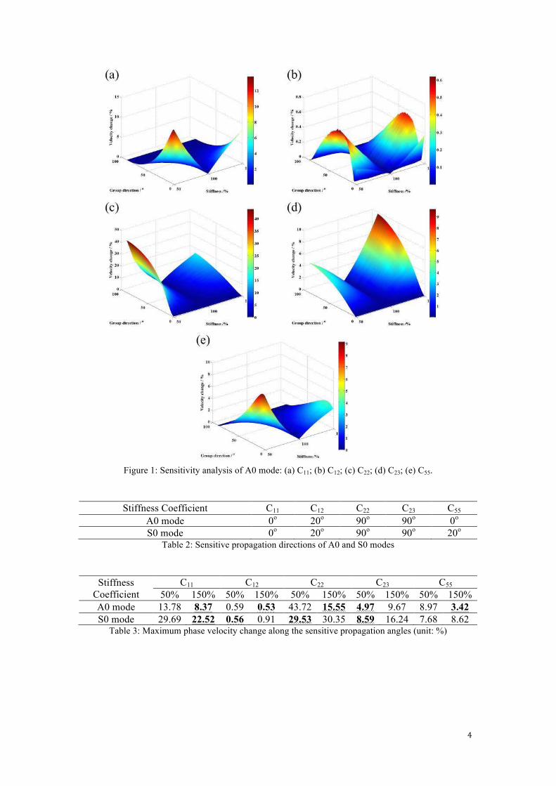
Figure 1: Sensitivity analysis of A0 mode: (a) C11; (b) C12; (c) C22; (d) C23; (e) C55.
Stiffness Coefficient C11 C12 C22 C23 C55
A0 mode 0o 20
o 90
o 90
o 0
o
S0 mode 0o 20
o 90
o 90
o 20
o
Table 2: Sensitive propagation directions of A0 and S0 modes
Stiffness
Coefficient
C11 C12 C22 C23 C55
50% 150% 50% 150% 50% 150% 50% 150% 50% 150%
A0 mode 13.78 8.37 0.59 0.53 43.72 15.55 4.97 9.67 8.97 3.42
S0 mode 29.69 22.52 0.56 0.91 29.53 30.35 8.59 16.24 7.68 8.62 Table 3: Maximum phase velocity change along the sensitive propagation angles (unit: %)
5
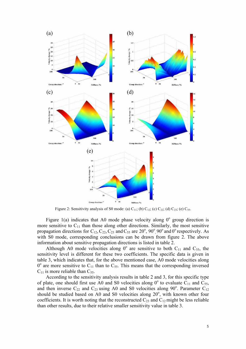
Figure 2: Sensitivity analysis of S0 mode: (a) C11; (b) C12; (c) C22; (d) C23; (e) C55.
Figure 1(a) indicates that A0 mode phase velocity along 0o group direction is
more sensitive to C11 than those along other directions. Similarly, the most sensitive
propagation directions for C12, C22, C23 and C55 are 20o, 90
o, 90
o and
0
o respectively. As
with S0 mode, corresponding conclusions can be drawn from figure 2. The above
information about sensitive propagation directions is listed in table 2.
Although A0 mode velocities along 0o are sensitive to both C11 and C55, the
sensitivity level is different for these two coefficients. The specific data is given in
table 3, which indicates that, for the above mentioned case, A0 mode velocities along
0o are more sensitive to C11 than to C55. This means that the corresponding inversed
C11 is more reliable than C55.
According to the sensitivity analysis results in table 2 and 3, for this specific type
of plate, one should first use A0 and S0 velocities along 0o to evaluate C11 and C55,
and then inverse C22 and C23 using A0 and S0 velocities along 90o. Parameter C12
should be studied based on A0 and S0 velocities along 20o, with known other four
coefficients. It is worth noting that the reconstructed C23 and C12 might be less reliable
than other results, due to their relative smaller sensitivity value in table 3.
6
4. GENETIC ALGORITHMS
Genetic algorithms (GAs) are stochastically search and optimization techniques which
mimic the natural process of evolution. GAs start with an initial guessed population
consisting of a certain number of individuals. In this research, each individual
represents a five-stiffness-coefficients candidate, and will be evaluated by the defined
error function. Those with smaller error will be kept, while others are regenerated
through crossover and mutation procedures. When the generation number achieves
the limit (or when the objective function value is smaller than a given number), the
iterative process is terminated and the corresponding individual denotes the
reconstructed material properties.
The inversion is carried out through GAs by minimizing the error function
err(C)|θ=
1
NA0+NS0
(vie-vit
vi
e
NA0
i=1+
vie-vit
vi
e
NS0
i=1) (5)
This error function is subjected to one group propagation direction θ. vie is the
experimental velocity at a certain frequency (index i), while vit is the theoretically
calculated one. �!! and �!! are the numbers of frequencies for A0 and S0 modes,
respectively.
5. EXPERIMENTAL SETUP AND RESULTS
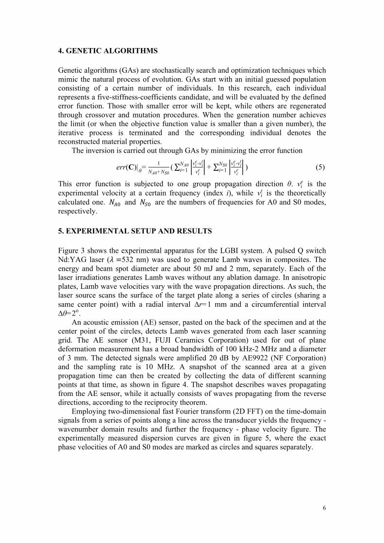
Figure 3 shows the experimental apparatus for the LGBI system. A pulsed Q switch
Nd:YAG laser (� =532 nm) was used to generate Lamb waves in composites. The
energy and beam spot diameter are about 50 mJ and 2 mm, separately. Each of the
laser irradiations generates Lamb waves without any ablation damage. In anisotropic
plates, Lamb wave velocities vary with the wave propagation directions. As such, the
laser source scans the surface of the target plate along a series of circles (sharing a
same center point) with a radial interval ∆r=1 mm and a circumferential interval
∆θ=2o.
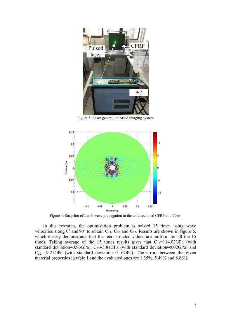
An acoustic emission (AE) sensor, pasted on the back of the specimen and at the
center point of the circles, detects Lamb waves generated from each laser scanning
grid. The AE sensor (M31, FUJI Ceramics Corporation) used for out of plane
deformation measurement has a broad bandwidth of 100 kHz-2 MHz and a diameter
of 3 mm. The detected signals were amplified 20 dB by AE9922 (NF Corporation)
and the sampling rate is 10 MHz. A snapshot of the scanned area at a given
propagation time can then be created by collecting the data of different scanning
points at that time, as shown in figure 4. The snapshot describes waves propagating
from the AE sensor, while it actually consists of waves propagating from the reverse
directions, according to the reciprocity theorem.
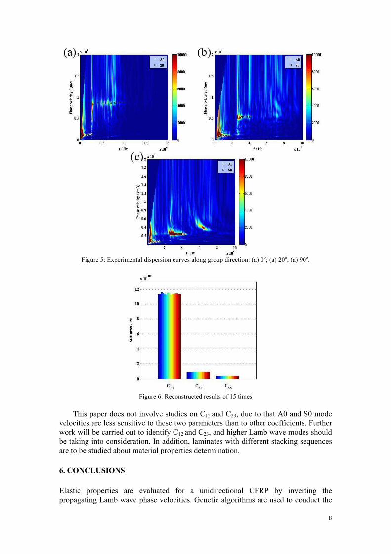
Employing two-dimensional fast Fourier transform (2D FFT) on the time-domain
signals from a series of points along a line across the transducer yields the frequency -
wavenumber domain results and further the frequency - phase velocity figure. The
experimentally measured dispersion curves are given in figure 5, where the exact
phase velocities of A0 and S0 modes are marked as circles and squares separately.
7
Figure 3: Laser generation based imaging system
Figure 4: Snapshot of Lamb wave propagation in the unidirectional CFRP at t=70��.
In this research, the optimization problem is solved 15 times using wave
velocities along 0o and
90
o to obtain C11, C55 and C22. Results are shown in figure 6,
which clearly demonstrates that the reconstructed values are uniform for all the 15
times. Taking average of the 15 times results gives that C11=114.02GPa (with
standard deviation=0.96GPa), C55=3.81GPa (with standard deviation=0.02GPa) and
C22= 9.21GPa (with standard deviation=0.16GPa). The errors between the given
material properties in table 1 and the evaluated ones are 1.35%, 5.49% and 8.86%.
8
Figure 5: Experimental dispersion curves along group direction: (a) 0
o; (a) 20
o; (a) 90
o.
Figure 6: Reconstructed results of 15 times
This paper does not involve studies on C12 and C23, due to that A0 and S0 mode
velocities are less sensitive to these two parameters than to other coefficients. Further
work will be carried out to identify C12 and C23, and higher Lamb wave modes should
be taking into consideration. In addition, laminates with different stacking sequences
are to be studied about material properties determination.
6. CONCLUSIONS
Elastic properties are evaluated for a unidirectional CFRP by inverting the
propagating Lamb wave phase velocities. Genetic algorithms are used to conduct the
9
inversion by minimizing the error between the measured and calculated velocities.
The experimental phase velocities are obtained through a laser-generation based
imaging system, while a semi-analytical finite element method is applied to
theoretically calculate the velocities.
The reconstructed C11, C55 and C22 are close to those given by the CFRP
manufacturer, while C12 and C23 can not be determined accurately since A0 and S0
mode velocities are not sensitive to these two parameters. Further researches need to
be conducted about C12 and C23 reconstruction.
ACKNOWLEDGEMENTS
This work is supported by the Major State Basic Research Development Program of
China (973 Program, No. 2015CB057501), the Fundamental Research Funds for the
Central Universities (No. NE2015001 & NE2015101), the Research Fund of State
Key Laboratory of Mechanics and Control of Mechanical Structures (No. 0515Y02),
the “333” project of Jiangsu Province (No. BRA2015310) and the Priority Academic
Program Development of Jiangsu Higher Education Institutions (PAPD).
REFERENCES
[1] M. D. Seale, B. T. Smith, and W. Prosser, "Lamb wave assessment of fatigue
and thermal damage in composites," The Journal of the Acoustical Society of
America, vol. 103, pp. 2416-2424, 1998.
[2] V. Dayal, V. Iyer, and V. Kinra, "Ultrasonic evaluation of microcracks in
composites," in ICF7, Houston (USA) 1989, 2013.
[3] Z. Su and L. Ye, Identification of damage using Lamb waves: from
fundamentals to applications vol. 48: Springer Science & Business Media,
2009.
[4] W. Rogers, "Elastic property measurement using Rayleigh-Lamb waves,"
Research in Nondestructive Evaluation, vol. 6, pp. 185-208, 1995.
[5] T.-T. Wu and Y.-H. Liu, "On the measurement of anisotropic elastic constants
of fiber-reinforced composite plate using ultrasonic bulk wave and laser
generated Lamb wave," Ultrasonics, vol. 37, pp. 405-412, 1999.
[6] J. Vishnuvardhan, C. Krishnamurthy, and K. Balasubramaniam, "Genetic
algorithm based reconstruction of the elastic moduli of orthotropic plates
using an ultrasonic guided wave single-transmitter-multiple-receiver SHM
array," Smart Materials and Structures, vol. 16, p. 1639, 2007.
[7] W. H. Ong, N. Rajic, W. K. Chiu, and C. Rosalie, "Determination of the
elastic properties of woven composite panels for Lamb wave studies,"
Composite Structures, vol. 141, 2016.
[8] J. Zhao, J. Qiu, and H. Ji, "Reconstruction of the nine stiffness coefficients of
composites using a laser generation based imaging method," Composites
Science and Technology, vol. 126, pp. 27-34, 2016.
[9] J. L. Rose, Ultrasonic waves in solid media: Cambridge university press,
2004.
[10] H. Gao, "Ultrasonic guided wave mechanics for composite material structural
health monitoring," The Pennsylvania State University, 2007.
[11] A. H. Nayfeh, Wave propagation in layered anisotropic media: With
application to composites: Elsevier, 1995.
10
[12] J. Zhao, H. Ji, and J. Qiu, "Modeling of Lamb waves in composites using new
third-order plate theories," Smart Materials and Structures, vol. 23, p. 045017,
2014.
[13] J. Zhao, J. Qiu, H. Ji, and N. Hu, "Four vectors of Lamb waves in composites:
Semianalysis and numerical simulation," Journal of Intelligent Material
Systems and Structures, p. 1045389X13488250, 2013.