Embed Size (px)
DESCRIPTION
ultrasonic testing principle,application,advantages etc
Citation preview
Ultrasonic testing in NDT
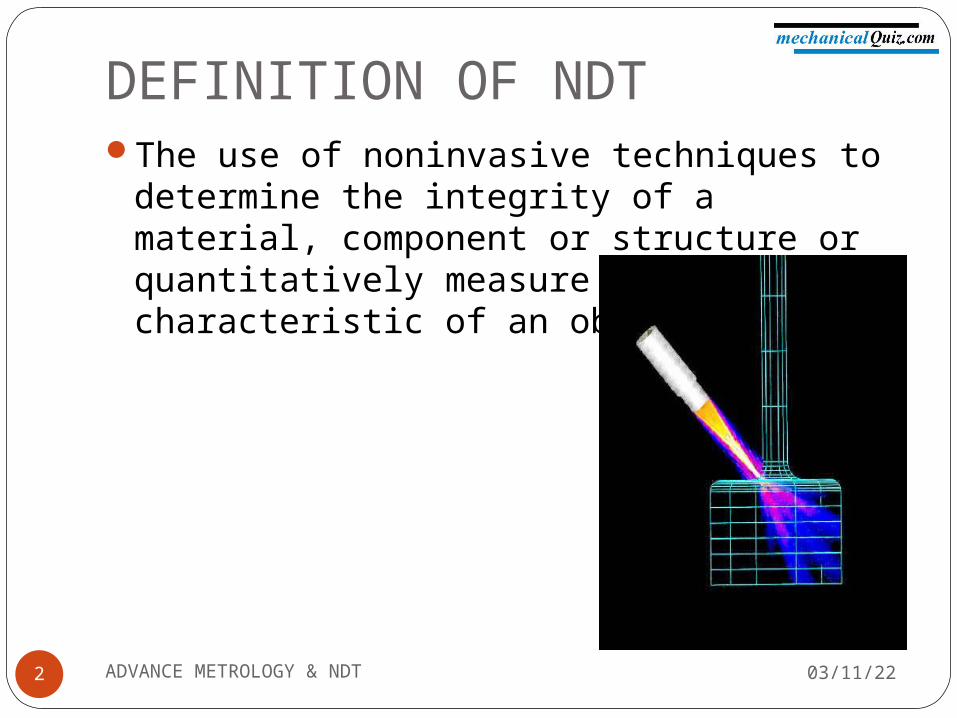
DEFINITION OF NDTThe use of noninvasive techniques to
determine the integrity of a material, component or structure or quantitatively measure some characteristic of an object.
04/07/232 ADVANCE METROLOGY & NDT
ULTRASONIC TESTINGUltrasonic testing uses high frequency sound
energy to conduct examinations and make measurements.
Ultrasonic examinations can be conducted on a wide variety of material forms including castings, forgings, welds, and composites.
A considerable amount of information about the part being examined can be collected, such as the presence of discontinuities, part or coating thickness; and acoustical properties can often be correlated to certain properties of the material.
04/07/233 ADVANCE METROLOGY & NDT
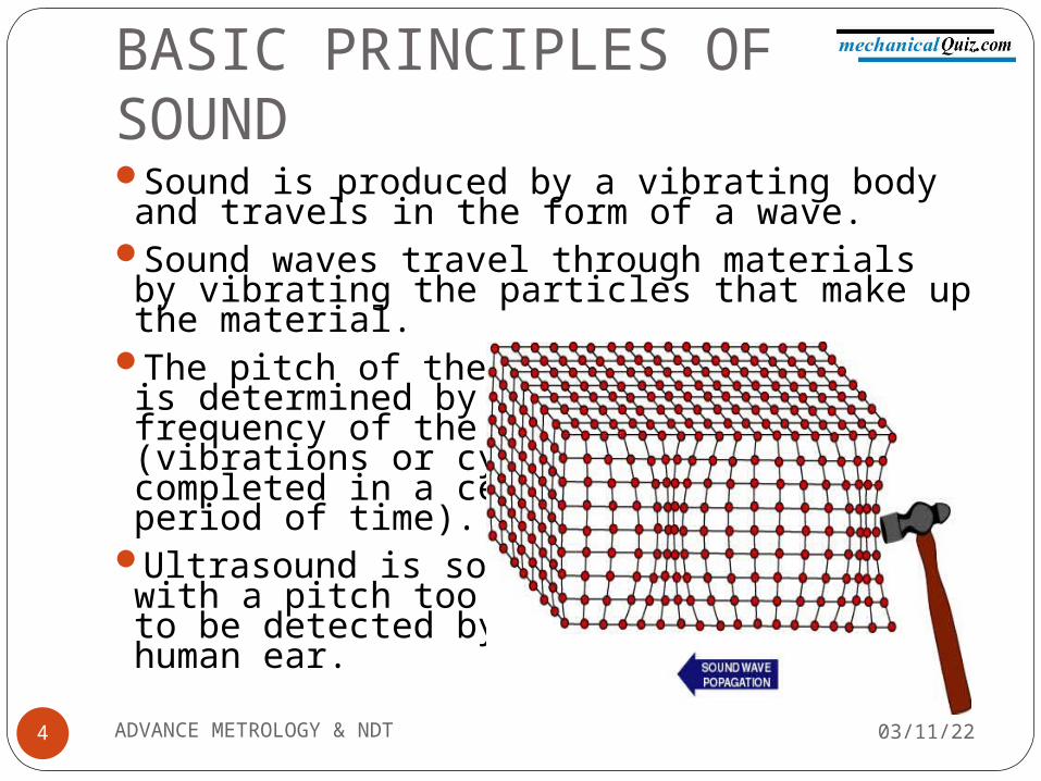
BASIC PRINCIPLES OF SOUNDSound is produced by a vibrating body and travels in the form of a wave.
Sound waves travel through materials by vibrating the particles that make up the material.
The pitch of the soundis determined by the frequency of the wave (vibrations or cycles completed in a certain period of time).
Ultrasound is soundwith a pitch too highto be detected by the human ear.
04/07/234 ADVANCE METROLOGY & NDT
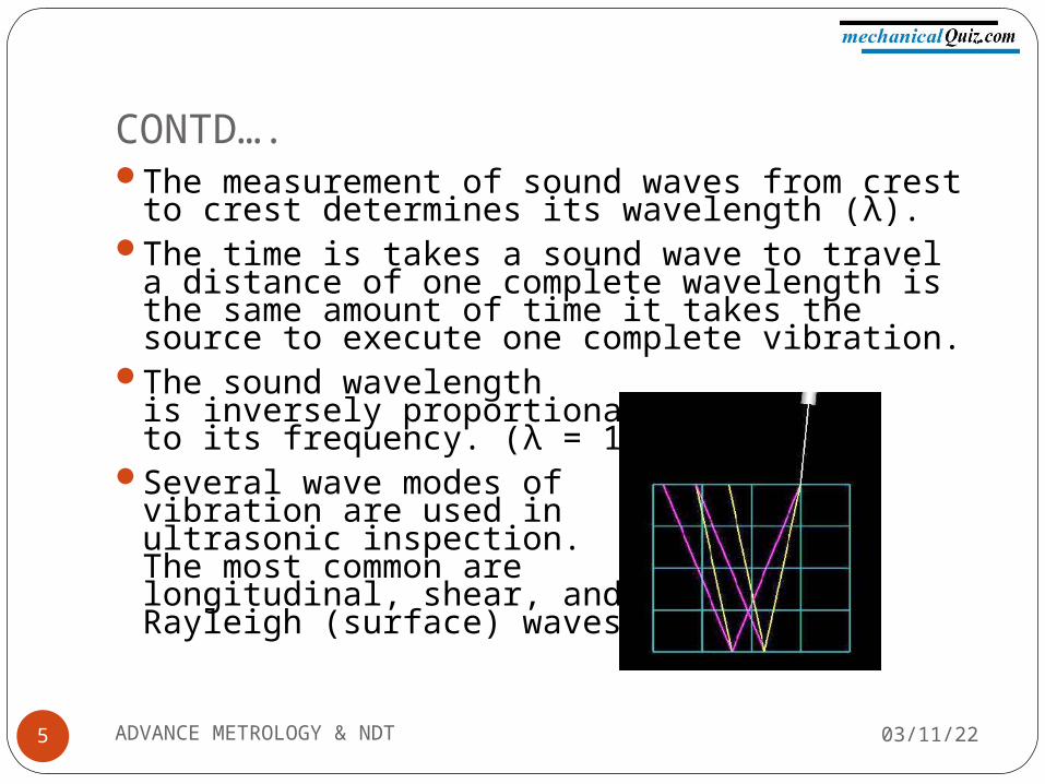
CONTD….The measurement of sound waves from crest
to crest determines its wavelength (λ).The time is takes a sound wave to travel a
distance of one complete wavelength is the same amount of time it takes the source to execute one complete vibration.
The sound wavelengthis inversely proportional to its frequency. (λ = 1/f)
Several wave modes of vibration are used in ultrasonic inspection.The most common arelongitudinal, shear, andRayleigh (surface) waves
04/07/235 ADVANCE METROLOGY & NDT
CONTD….Ultrasonic waves are very similar to light waves
in that they can be reflected, refracted, and focused.
Reflection and refraction occurs when sound waves interact with interfaces of differing acoustic properties.
In solid materials, the vibrational energy can be split into different wave modes when the wave encounters an interface at an angle other than 90 degrees.
Ultrasonic reflections from the presence of discontinuities or geometric features enables detection and location.
The velocity of sound in a given material is constant and can only be altered by a change in the mode of energy.
04/07/236 ADVANCE METROLOGY & NDT
ULTRASOUND GENERATION
04/07/23ADVANCE METROLOGY & NDT7
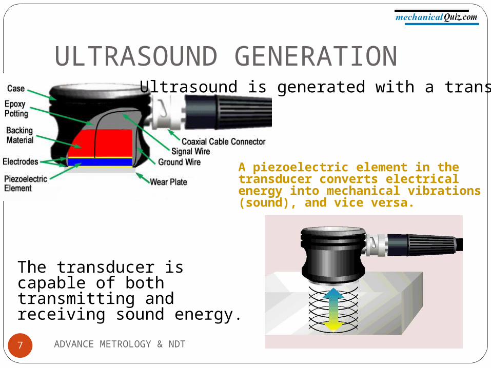
A piezoelectric element in the transducer converts electrical energy into mechanical vibrations (sound), and vice versa.
The transducer is capable of both transmitting and receiving sound energy.
Ultrasound is generated with a transducer.
Principles of Ultrasonic Inspection
04/07/23ADVANCE METROLOGY & NDT8
Ultrasonic waves are introduced into a material where they travel in a straight line and at a constant speed until they encounter a surface.
At surface interfaces some of the wave energy is reflected and some is transmitted.
The amount of reflected or transmitted energy can be detected and provides information about the size of the reflector.
The travel time of the sound can be measured and this provides information on the distance that the sound has traveled.
Test Techniques
04/07/23ADVANCE METROLOGY & NDT9
Ultrasonic testing is a very versatile inspection method, and inspections can be accomplished in a number of different ways.
Ultrasonic inspection techniques are commonly divided into three primary classifications.Pulse-echo and Through Transmission
(Relates to whether reflected or transmitted energy is used)
Normal Beam and Angle Beam(Relates to the angle that the sound energy enters the test article)
Contact and Immersion(Relates to the method of coupling the transducer to the test article)
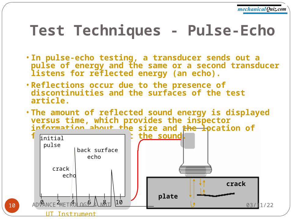
• In pulse-echo testing, a transducer sends out a pulse of energy and the same or a second transducer listens for reflected energy (an echo).
• Reflections occur due to the presence of discontinuities and the surfaces of the test article.
• The amount of reflected sound energy is displayed versus time, which provides the inspector information about the size and the location of features that reflect the sound.
f
Test Techniques - Pulse-Echo
plate
crack
0 2 4 6 8 10
initial pulse
crack echo
back surface echo
UT Instrument Screen04/07/2310 ADVANCE METROLOGY & NDT
Test Techniques – Pulse-Echo (cont.)
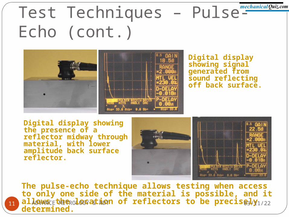
Digital display showing signal generated from sound reflecting off back surface.
Digital display showing the presence of a reflector midway through material, with lower amplitude back surface reflector.
The pulse-echo technique allows testing when access to only one side of the material is possible, and it allows the location of reflectors to be precisely determined. 04/07/2311 ADVANCE METROLOGY & NDT
Test Techniques – Normal and Angle Beam
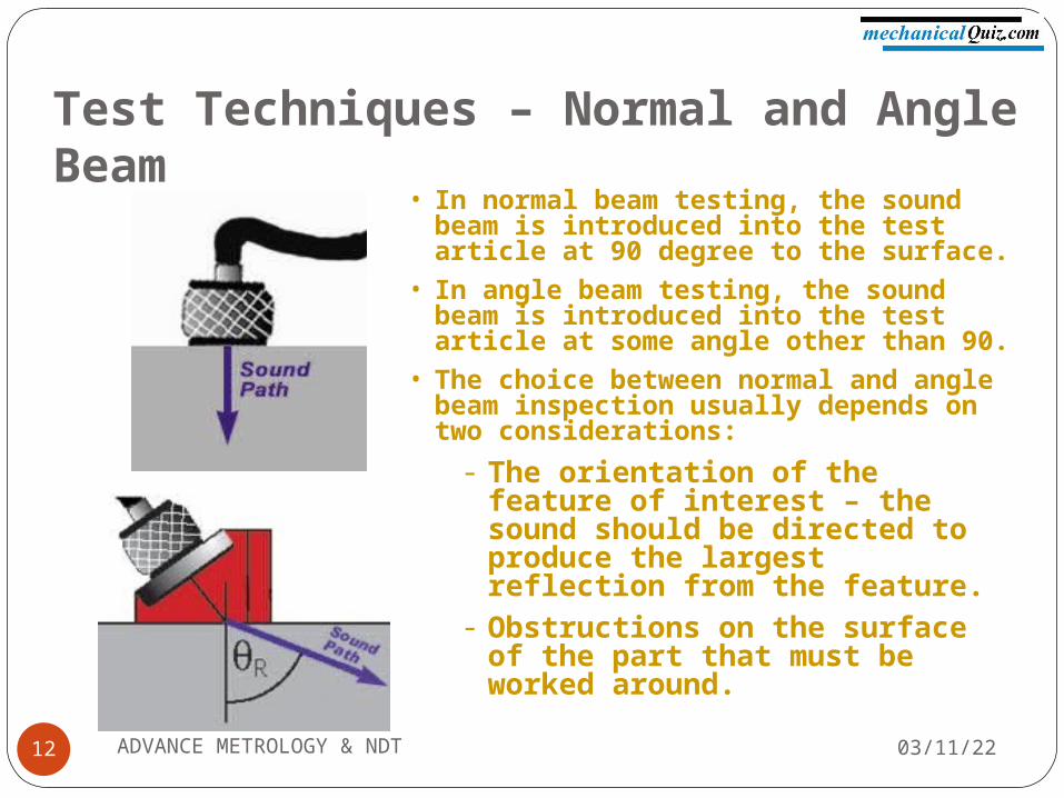
• In normal beam testing, the sound beam is introduced into the test article at 90 degree to the surface.
• In angle beam testing, the sound beam is introduced into the test article at some angle other than 90.
• The choice between normal and angle beam inspection usually depends on two considerations:
- The orientation of the feature of interest – the sound should be directed to produce the largest reflection from the feature.
- Obstructions on the surface of the part that must be worked around.
04/07/2312 ADVANCE METROLOGY & NDT
0 2 4 6 8 10
FWE
BWEDE
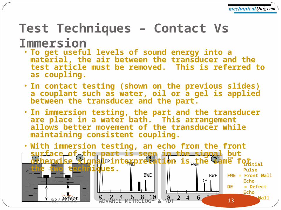
2IPIP = Initial PulseFWE = Front Wall
EchoDE = Defect EchoBWE = Back Wall
Echo
0 2 4 6 8 10
FWE
BWE
1IP1 2
Defect
Test Techniques – Contact Vs Immersion
• To get useful levels of sound energy into a material, the air between the transducer and the test article must be removed. This is referred to as coupling.
• In contact testing (shown on the previous slides) a couplant such as water, oil or a gel is applied between the transducer and the part.
• In immersion testing, the part and the transducer are place in a water bath. This arrangement allows better movement of the transducer while maintaining consistent coupling.
• With immersion testing, an echo from the front surface of the part is seen in the signal but otherwise signal interpretation is the same for the two techniques.
04/07/23 13ADVANCE METROLOGY & NDT
Inspection Applications
04/07/23ADVANCE METROLOGY & NDT14
Flaw detection (cracks, inclusions, porosity, etc.)
Erosion & corrosion thickness gaugingAssessment of bond integrity in adhesively
joined and brazed componentsEstimation of void content in composites
and plasticsMeasurement of case hardening depth in
steelsEstimation of grain size in metals
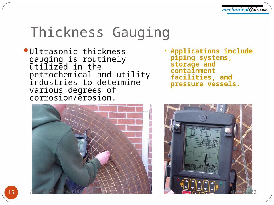
Thickness GaugingUltrasonic thickness gauging
is routinely utilized in the petrochemical and utility industries to determine various degrees of corrosion/erosion.
• Applications include piping systems, storage and containment facilities, and pressure vessels.
04/07/2315 ADVANCE METROLOGY & NDT
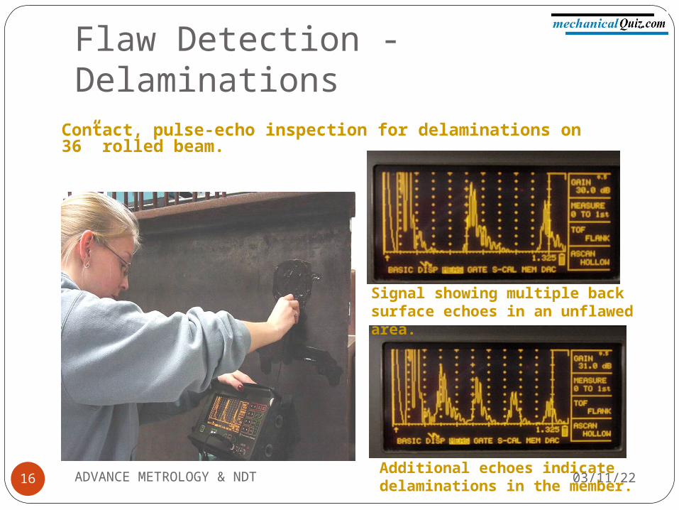
Flaw Detection - Delaminations
Signal showing multiple back surface echoes in an unflawed area.
Additional echoes indicate delaminations in the member.
Contact, pulse-echo inspection for delaminations on 36” rolled beam.
04/07/2316 ADVANCE METROLOGY & NDT
Flaw Detection in Welds
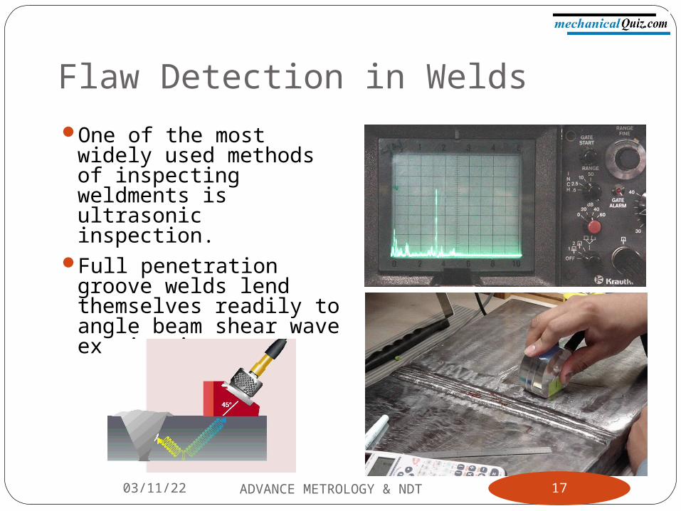
One of the most widely used methods of inspecting weldments is ultrasonic inspection.
Full penetration groove welds lend themselves readily to angle beam shear wave examination.
04/07/23 17ADVANCE METROLOGY & NDT
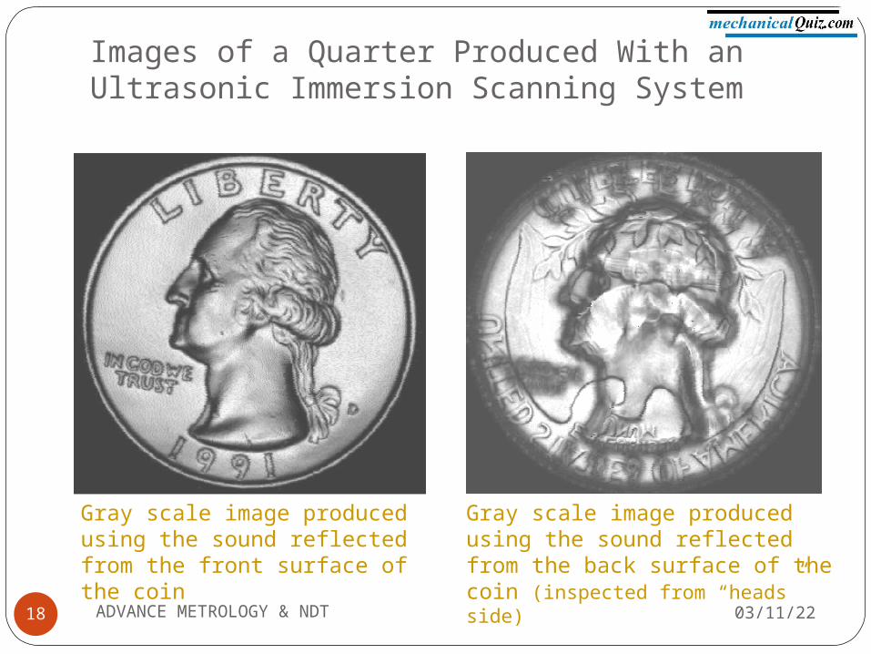
Images of a Quarter Produced With an Ultrasonic Immersion Scanning System
Gray scale image produced using the sound reflected from the front surface of the coin
Gray scale image produced using the sound reflected from the back surface of the coin (inspected from “heads” side)
04/07/2318 ADVANCE METROLOGY & NDT
ADVANTAGES
04/07/23ADVANCE METROLOGY & NDT19
Sensitive to small discontinuities both surface and subsurface.
Depth of penetration for flaw detection or measurement is superior to other methods.
Only single-sided access is needed when pulse-echo technique is used.
High accuracy in determining reflector position and estimating size and shape.
Electronic equipment provides instantaneous results.
Detailed images can be produced with automated systems.
Has other uses such as thickness measurements, in addition to flaw detection.
LIMITATIONS
04/07/23ADVANCE METROLOGY & NDT20
Surface must be accessible to transmit ultrasound.
Normally requires a coupling medium to promote transfer of sound energy into test specimen.
Materials that are rough, irregular in shape, very small, exceptionally thin or not homogeneous are difficult to inspect.
Cast iron and other coarse grained materials are difficult to inspect due to low sound transmission and high signal noise.
Linear defects oriented parallel to the sound beam may go undetected.
Reference standards are required for both equipment calibration, and characterization of flaws

04/07/23ADVANCE METROLOGY & NDT21
Presented by

04/07/23ADVANCE METROLOGY & NDT22
THANK U


![Ultrasonic Testing of Rails Using Phased Array - ndt.net · Ultrasonic testing is widely employed for Non-destructive Testing (NDT) [1] of test objects to detect and analyse anomalies](https://img.pdfslide.net/doc/110x75/5b4f2ad37f8b9a3e6e8bc326/ultrasonic-testing-of-rails-using-phased-array-ndtnet-ultrasonic-testing.jpg)


![Ndt Training - Ultrasonic Methode[1]](https://img.pdfslide.net/doc/110x75/5571f88c49795991698da7a2/ndt-training-ultrasonic-methode1.jpg)