Embed Size (px)
Citation preview
www.afm-journal.de
FULL P
APER
www.MaterialsViews.com
Shu Zhu , Ju-Hee So , Robin Mays , Sharvil Desai , William R. Barnes , Behnam Pourdeyhimi , and Michael D. Dickey *
Ultrastretchable Fibers with Metallic Conductivity Using a Liquid Metal Alloy Core
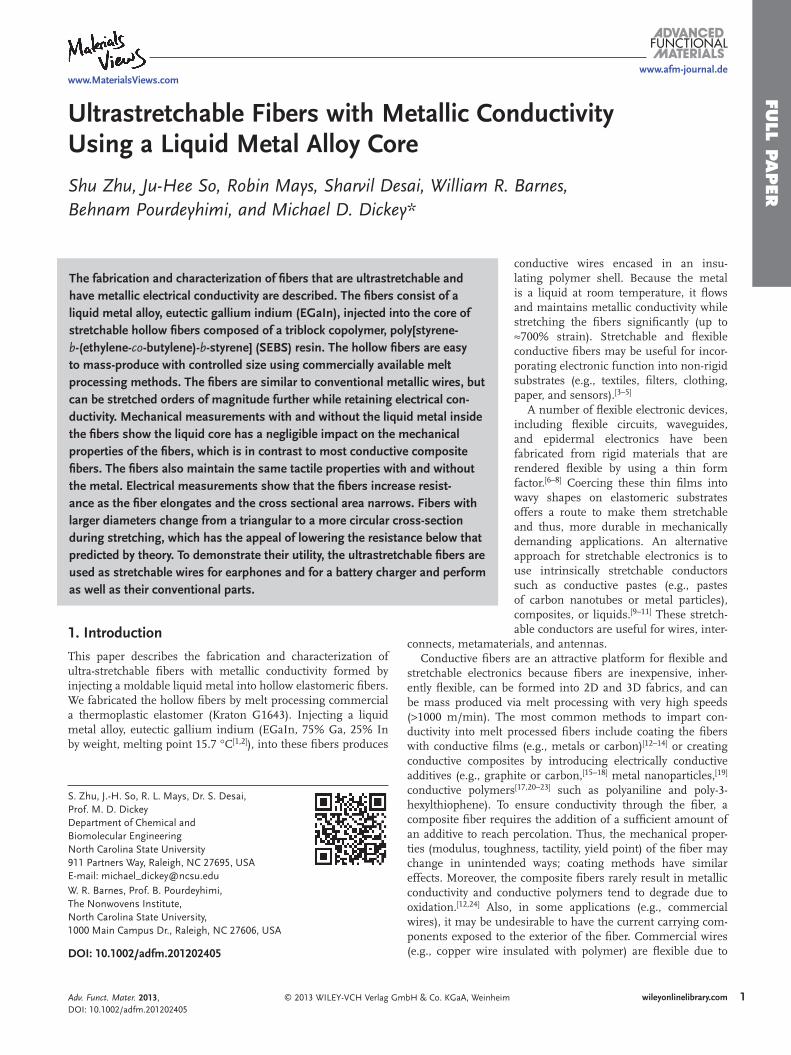
The fabrication and characterization of fi bers that are ultrastretchable and have metallic electrical conductivity are described. The fi bers consist of a liquid metal alloy, eutectic gallium indium (EGaIn), injected into the core of stretchable hollow fi bers composed of a triblock copolymer, poly[styrene- b -(ethylene- co -butylene)- b -styrene] (SEBS) resin. The hollow fi bers are easy to mass-produce with controlled size using commercially available melt processing methods. The fi bers are similar to conventional metallic wires, but can be stretched orders of magnitude further while retaining electrical con-ductivity. Mechanical measurements with and without the liquid metal inside the fi bers show the liquid core has a negligible impact on the mechanical properties of the fi bers, which is in contrast to most conductive composite fi bers. The fi bers also maintain the same tactile properties with and without the metal. Electrical measurements show that the fi bers increase resist-ance as the fi ber elongates and the cross sectional area narrows. Fibers with larger diameters change from a triangular to a more circular cross-section during stretching, which has the appeal of lowering the resistance below that predicted by theory. To demonstrate their utility, the ultrastretchable fi bers are used as stretchable wires for earphones and for a battery charger and perform as well as their conventional parts.
1. Introduction
This paper describes the fabrication and characterization of ultra-stretchable fi bers with metallic conductivity formed by injecting a moldable liquid metal into hollow elastomeric fi bers. We fabricated the hollow fi bers by melt processing commercial a thermoplastic elastomer (Kraton G1643). Injecting a liquid metal alloy, eutectic gallium indium (EGaIn, 75% Ga, 25% In by weight, melting point 15.7 ° C [ 1 , 2 ] ), into these fi bers produces
© 2013 WILEY-VCH Verlag GmbH & Co. KGaA, Weinhei
DOI: 10.1002/adfm.201202405
S. Zhu, J.-H. So, R. L. Mays, Dr. S. Desai, Prof. M. D. Dickey Department of Chemical and Biomolecular Engineering North Carolina State University 911 Partners Way, Raleigh, NC 27695, USA E-mail: [email protected] W. R. Barnes, Prof. B. Pourdeyhimi, The Nonwovens Institute, North Carolina State University, 1000 Main Campus Dr., Raleigh, NC 27606, USA
Adv. Funct. Mater. 2013, DOI: 10.1002/adfm.201202405
conductive wires encased in an insu-lating polymer shell. Because the metal is a liquid at room temperature, it fl ows and maintains metallic conductivity while stretching the fi bers signifi cantly (up to ≈ 700% strain). Stretchable and fl exible conductive fi bers may be useful for incor-porating electronic function into non-rigid substrates (e.g., textiles, fi lters, clothing, paper, and sensors). [ 3–5 ]
A number of fl exible electronic devices, including fl exible circuits, waveguides, and epidermal electronics have been fabricated from rigid materials that are rendered fl exible by using a thin form factor. [ 6–8 ] Coercing these thin fi lms into wavy shapes on elastomeric substrates offers a route to make them stretchable and thus, more durable in mechanically demanding applications. An alternative approach for stretchable electronics is to use intrinsically stretchable conductors such as conductive pastes (e.g., pastes of carbon nanotubes or metal particles), composites, or liquids. [ 9–11 ] These stretch-able conductors are useful for wires, inter-
connects, metamaterials, and antennas. Conductive fi bers are an attractive platform for fl exible and
stretchable electronics because fi bers are inexpensive, inher-ently fl exible, can be formed into 2D and 3D fabrics, and can be mass produced via melt processing with very high speeds ( > 1000 m/min). The most common methods to impart con-ductivity into melt processed fi bers include coating the fi bers with conductive fi lms (e.g., metals or carbon) [ 12–14 ] or creating conductive composites by introducing electrically conductive additives (e.g., graphite or carbon, [ 15–18 ] metal nanoparticles, [ 19 ] conductive polymers [ 17 , 20–23 ] such as polyaniline and poly-3-hexylthiophene). To ensure conductivity through the fi ber, a composite fi ber requires the addition of a suffi cient amount of an additive to reach percolation. Thus, the mechanical proper-ties (modulus, toughness, tactility, yield point) of the fi ber may change in unintended ways; coating methods have similar effects. Moreover, the composite fi bers rarely result in metallic conductivity and conductive polymers tend to degrade due to oxidation. [ 12 , 24 ] Also, in some applications (e.g., commercial wires), it may be undesirable to have the current carrying com-ponents exposed to the exterior of the fi ber. Commercial wires (e.g., copper wire insulated with polymer) are fl exible due to
m 1wileyonlinelibrary.com
FULL
PAPER
2
www.afm-journal.dewww.MaterialsViews.com
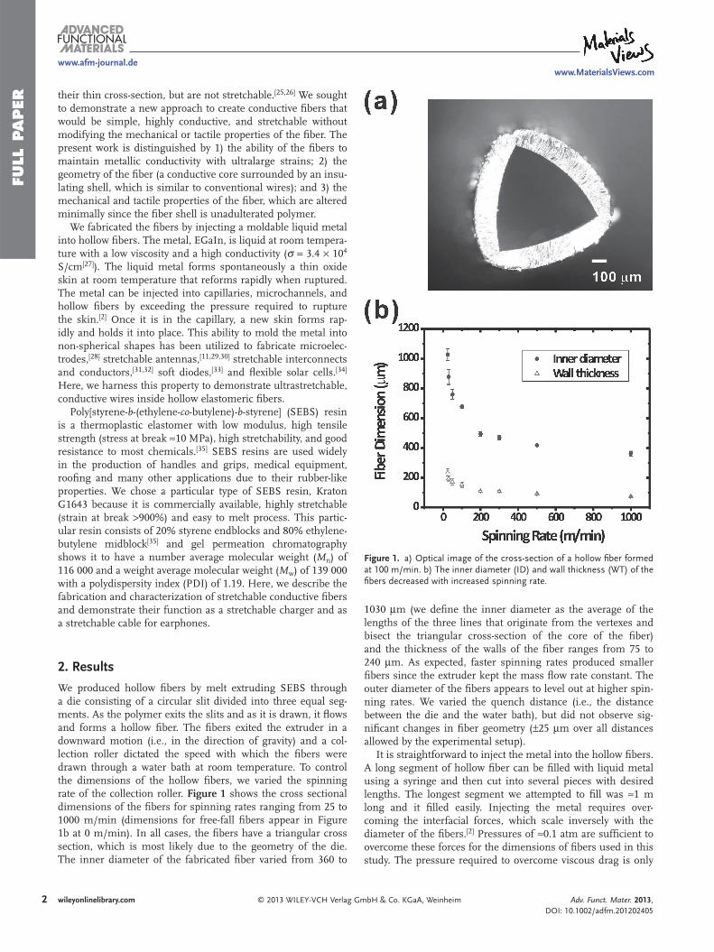
Figure 1 . a) Optical image of the cross-section of a hollow fi ber formed at 100 m/min. b) The inner diameter (ID) and wall thickness (WT) of the fi bers decreased with increased spinning rate.
their thin cross-section, but are not stretchable. [ 25 , 26 ] We sought to demonstrate a new approach to create conductive fi bers that would be simple, highly conductive, and stretchable without modifying the mechanical or tactile properties of the fi ber. The present work is distinguished by 1) the ability of the fi bers to maintain metallic conductivity with ultralarge strains; 2) the geometry of the fi ber (a conductive core surrounded by an insu-lating shell, which is similar to conventional wires); and 3) the mechanical and tactile properties of the fi ber, which are altered minimally since the fi ber shell is unadulterated polymer.
We fabricated the fi bers by injecting a moldable liquid metal into hollow fi bers. The metal, EGaIn, is liquid at room tempera-ture with a low viscosity and a high conductivity ( σ = 3.4 × 10 4 S/cm [ 27 ] ). The liquid metal forms spontaneously a thin oxide skin at room temperature that reforms rapidly when ruptured. The metal can be injected into capillaries, microchannels, and hollow fi bers by exceeding the pressure required to rupture the skin. [ 2 ] Once it is in the capillary, a new skin forms rap-idly and holds it into place. This ability to mold the metal into non-spherical shapes has been utilized to fabricate microelec-trodes, [ 28 ] stretchable antennas, [ 11 , 29 , 30 ] stretchable interconnects and conductors, [ 31 , 32 ] soft diodes, [ 33 ] and fl exible solar cells. [ 34 ] Here, we harness this property to demonstrate ultrastretchable, conductive wires inside hollow elastomeric fi bers.
Poly[styrene- b -(ethylene- co -butylene)- b -styrene] (SEBS) resin is a thermoplastic elastomer with low modulus, high tensile strength (stress at break ≈ 10 MPa), high stretchability, and good resistance to most chemicals. [ 35 ] SEBS resins are used widely in the production of handles and grips, medical equipment, roofi ng and many other applications due to their rubber-like properties. We chose a particular type of SEBS resin, Kraton G1643 because it is commercially available, highly stretchable (strain at break > 900%) and easy to melt process. This partic-ular resin consists of 20% styrene endblocks and 80% ethylene-butylene midblock [ 35 ] and gel permeation chromatography shows it to have a number average molecular weight ( M n ) of 116 000 and a weight average molecular weight ( M w ) of 139 000 with a polydispersity index (PDI) of 1.19. Here, we describe the fabrication and characterization of stretchable conductive fi bers and demonstrate their function as a stretchable charger and as a stretchable cable for earphones.
2. Results
We produced hollow fi bers by melt extruding SEBS through a die consisting of a circular slit divided into three equal seg-ments. As the polymer exits the slits and as it is drawn, it fl ows and forms a hollow fi ber. The fi bers exited the extruder in a downward motion (i.e., in the direction of gravity) and a col-lection roller dictated the speed with which the fi bers were drawn through a water bath at room temperature. To control the dimensions of the hollow fi bers, we varied the spinning rate of the collection roller. Figure 1 shows the cross sectional dimensions of the fi bers for spinning rates ranging from 25 to 1000 m/min (dimensions for free-fall fi bers appear in Figure 1 b at 0 m/min). In all cases, the fi bers have a triangular cross section, which is most likely due to the geometry of the die. The inner diameter of the fabricated fi ber varied from 360 to
wileyonlinelibrary.com © 2013 WILEY-VCH Verlag G
1030 μ m (we defi ne the inner diameter as the average of the lengths of the three lines that originate from the vertexes and bisect the triangular cross-section of the core of the fi ber) and the thickness of the walls of the fi ber ranges from 75 to 240 μ m. As expected, faster spinning rates produced smaller fi bers since the extruder kept the mass fl ow rate constant. The outer diameter of the fi bers appears to level out at higher spin-ning rates. We varied the quench distance (i.e., the distance between the die and the water bath), but did not observe sig-nifi cant changes in fi ber geometry ( ± 25 μ m over all distances allowed by the experimental setup).
It is straightforward to inject the metal into the hollow fi bers. A long segment of hollow fi ber can be fi lled with liquid metal using a syringe and then cut into several pieces with desired lengths. The longest segment we attempted to fi ll was ≈ 1 m long and it fi lled easily. Injecting the metal requires over-coming the interfacial forces, which scale inversely with the diameter of the fi bers. [ 2 ] Pressures of ≈ 0.1 atm are suffi cient to overcome these forces for the dimensions of fi bers used in this study. The pressure required to overcome viscous drag is only
mbH & Co. KGaA, Weinheim Adv. Funct. Mater. 2013, DOI: 10.1002/adfm.201202405

FULL P
APER
www.afm-journal.dewww.MaterialsViews.com
Figure 2 . a) A relaxed, 2 cm section of an ultrastretchable conductive fi ber. The shiny core of its cross-section (inset) is the liquid metal. b) The fi ber is stretched to 20 cm and the metal appears to uniformly fi ll the stretched fi ber.
signifi cant at large injection velocities or long lengths of fi ber due to the low viscosity of the metal. The oxidized skin of the metal prevents the metal from fl owing out of the fi ber when the fi ber is not disturbed (e.g., squeezed signifi cantly). The inset in Figure 2 a shows that the metal remains fl ush with the cut end of the fi ber.
We hypothesized that the incorporation of the metal impacts minimally the mechanical properties of the fi bers since the metal is a low viscosity liquid and fl ows readily in response to applied strain. An extensometer measured the mechanical properties of both the hollow and fi lled fi bers. Figure 3 shows the stress–strain profi les of the fi bers for two spinning rates
© 2013 WILEY-VCH Verlag Gm
Figure 3 . The stress–strain plots of elastomeric hollow (hollow symbols) and fi lled (solid lines) fi bers with two different spinning rates. The fi bers have the same mechanical properties with and without the metal.
Adv. Funct. Mater. 2013, DOI: 10.1002/adfm.201202405
spanning an order of magnitude in spin speed (100 m/min and 1000 m/min). The plots show the typical properties of ther-moplastic elastomers: low modulus and high tensile strength. Although the fi bers have very similar mechanical properties, as expected, fi bers made with the lowest spinning rate can be strained the furthest before the point of failure. At the lowest spinning rate (100 m/min), we found that the fi bers could be stretched to 800–1000% strain before reaching the point of failure. Figure 3 shows that the fi bers with and without the metal have nearly identical mechanical properties, which illus-trates the negligible effects of the liquid metal on the mechan-ical properties of the fi bers.
For many applications, a practical consideration is the effect of multiple strain cycles on the performance of the fi ber. We performed cyclic testing on the fi bers produced at 1000 m/min to quantify the effects of repeated strain on the mechanical properties. Figure 4 a shows that after the fi rst cycle (0 to 800 to 0% strain), subsequent strain cycles overlap nearly perfectly with minimal signs of hysteresis. After the fi rst cycle, there is ≈ 50% unrecoverable strain (i.e., the “set”), which does not change with subsequent cycles. This result suggests there is some plastic deformation during the fi rst strain cycle, but negli-gible plastic deformation during subsequent cycles. Fibers fab-ricated with other spinning rates showed similar behavior. We also performed cyclic testing on the fi bers at lower amounts of strain (0 to 50 to 0% strain), which may be more representa-tive of strains encountered in actual applications (e.g., textiles). At these strain cycles, there is only ≈ 5% unrecoverable strain (Figure 4 b). At extreme levels of strain (i.e., 800%), the fi bers produced at 1000 m/min broke after 20–40 cycles. The dura-bility improved for fi bers produced at 100 m/min, which broke typically after 80–100 cycles at 800% strain. At intermediate strains (i.e., 50% and 400% strain), the fi bers did not break after hundreds of cycles.
3wileyonlinelibrary.combH & Co. KGaA, Weinheim

FULL
PAPER
www.afm-journal.de
Figure 4 . Cyclic tests of the mechanical properties of the hollow fi bers fabricated with a spinning rate of 1000 m/min at a) 800% and b) 50% strain. The fi rst cycle is indicated with a dashed line and subsequent cycles are solid lines. A vertical line marks the amount of unrecoverable strain resulting from plastic deformation.
Figure 5 . The experimental (fi lled squares) and theoretical resistance (empty triangles and circles) of conductive fi bers with two different spinning rates of a) 100 and b) 1000 m/min. The triangles indicate the geometrical effects of elongation and the circles represent the effect of changes in cross-sectional geometry during elongation.
The electrical resistance of the fi ber should increase as a func-tion of applied strain since the length of the fi ber increases while the cross-sectional area decreases. We measured the resistance as a function of strain and normalized all measurements by the resistance at zero strain such that the initial normalized resist-ance is 1. The resistance R of a wire depends on its resistivity ρ , length L , and cross-sectional area A , as described in Pouillet’s law. Assuming that the polymer sheath has a Poisson’s ratio of 0.5 and the metal is incompressible, then the resistance of the fi ber should be proportional to the change in the square of the length based solely on geometry. We developed two sets of theoretical resistance values: one is based on the assumption that the cross-sectional area remains triangular while stretching and the other one assumes it becomes circular (i.e., for a given circumference, the cross-sectional area for a circle is 65% larger than an equilateral triangle and thus, the resistance through
4 wileyonlinelibrary.com © 2013 WILEY-VCH Verlag G
www.MaterialsViews.com
a circular cross section should be lower). The experimental data, in principle, should be within these bounds for the given assumptions.
Figure 5 shows that the resistance increases as a function of strain. The fi bers with a smaller cross sectional area (1000 m/min) have an electrical resistance that agrees nearly perfectly with that predicted by the model for a triangular cross-sectional area. The resistance of these fi bers increases dramatically beyond the last plotted point ( ≈ 600% strain). The fi bers with a larger cross sectional area (100 m/min) initially have an electrical resistance similar to the theoretical resistance for a triangular cross sec-tion but then deviate gradually to lower values and follow the resistance prediction for a circular cross-section until 700–800% strain, at which point the resistance rises rapidly. The fi bers maintained electrical continuity to ≈ 1000% strain, albeit at sig-nifi cantly higher resistances. Figure 5 a represents the best case
mbH & Co. KGaA, Weinheim Adv. Funct. Mater. 2013, DOI: 10.1002/adfm.201202405

FULL P
APER
www.afm-journal.dewww.MaterialsViews.com
Figure 6 . a) Stretchable charger for an iPod and b) stretchable cable for earphones.
scenario; in some samples (100 m/min), the resistance would increase rapidly as low as 400% strain. The loss of conductivity coincides with the physical collapse of the fi bers. The metallic conductivity recovers upon returning the fi bers back to a non-stressed state (in some cases, massaging the fi bers is required to regain continuity).
The geometric model captures the general trends in Figure 5 and suggests that the resistance is less than or equal to that expected from a triangular shaped fi ber. We compared the cross-sectional geometry of the 100 and 1000 m/min fi bers during elon-gation. The cross-section of the fi ber with 100 m/min spinning rate appears to become circular while the fi bers with 1000 m/min spinning rate maintain their triangular cross section (see Figure S1,S2 in the Supporting Information), which is consistent with the results of Figure 5 . The ability of the fi bers produced at 1000 m/min to maintain a triangular profi le during elonga-tion could be a result of the smaller size (i.e., increasing the circumference of the fi ber should make the side walls easier to deform). Regardless of these subtle effects, the key advance of this work is the remarkable conductivity at large strains.
The fi bers have a resistivity of ≈ 3 × 10 − 5 Ω cm until the strain at which the resistance increases rapidly. This value is expected based on the conductivity of the metal (some papers in the literature utilize units of resistance normalized by the length of the fi ber, in which case the 100 m/min and 1000 m/min fi bers at 500% strain have values of 0.08 and 0.24 Ω /cm). This metallic conductivity exceeds the most conductive composite fi bers in the literature (by approximately a factor of 30) [ 36 ] and the resistivity is within an order of magnitude of conventional rigid copper wires. The elongation also nearly matches some of the most stretchable conductive fi bers in the literature while exceeding the conductivity by four orders of magnitude. [ 22 ]
A potential drawback of a liquid core encased in an elasto-meric shell is that the metal can fl ow and increase its resistance when pinched. We performed some qualitative experiments to emulate conditions the fi ber may encounter during handling. We intentionally pinched the 100 m/min fi ber using pressure from our fi ngers and found the resistance to increase by an order of magnitude, but not lose electrical continuity. The resist-ance returned to its initial value when we stopped pinching the fi ber. The resistance increased two orders of magnitude, but did not lose its electrical continuity when we concentrated the pres-sure using our fi nger nails. The resistance recovered to its pre-pinched value after releasing the force and massaging the fi ber. These qualitative experiments underscore a limitation of using soft materials, yet suggest that it is challenging to completely eliminate electrical continuity by hand.
To demonstrate the utility of stretchable fi bers in electronic applications, we utilized the fi bers as wires of a charger and earphones for a portable music player (iPod). We cut a por-tion of an iPod charger line and inserted four stretchable fi bers (two power wires and two data transmission wires) as shown in Figure 6 a. We used adhesive to bond the stretchable fi bers to the rigid wires of the iPod. The iPod began charging when connected to a computer through the stretchable charger, and continued charging while we repeatedly stretched and relaxed the fi bers (see Video S1 in the Supporting information). We found that the stretchable charger replenished the battery at approximately the same rate as the commercial charger (see
© 2013 WILEY-VCH Verlag GmAdv. Funct. Mater. 2013, DOI: 10.1002/adfm.201202405
Supporting Information). We also inserted the fi bers to replace a portion of the wires for earphones (Figure 6 b) and the ear-phones continued to play music without noticeable degreda-tion to volume or sound quality when elongated (see Video S2 in the Supporting information). We repeated several tens of cycles of stretching ( ≈ 300% strain) and relaxing the wires of the iPod charger and the earphones and their performance did not change in any apparent way. In both examples, the stretchable fi bers have a lower resistance per unit length than the commer-cial wires and thus it is expected that there should be no degra-dation in performance.
3. Conclusion
This study provides an alternative approach to generate ultra-stretchable conductive fi bers by simply injecting liquid alloy (EGaIn) into hollow polymeric (Kraton SEBS) fi bers. The dimensions of the conductive fi bers can be manipulated by var-ying the spinning rate of collecting rollers during the melt spin-ning process. The fi bers have the same mechanical and tactile
5wileyonlinelibrary.combH & Co. KGaA, Weinheim
FULL
PAPER
www.afm-journal.dewww.MaterialsViews.com
properties with and without the metal. Metallic electrical conti-nuity can be maintained to greater than 700% strain depending on the dimensions of the fi ber, which we believe represents one of the best combinations of conductivity and stretchability for conductive fi bers reported to date. The conductive fi bers can be incorporated into numerous applications including fl exible elec-tronics, smart garments, stretchable wires, inductors, intercon-nects, and antennas. A limitation of this approach is the liquid core of the fi bers can collapse under concentrated pressure or at large strains, although conductivity can be restored. For appli-cations that do not require ultra-stretchability, other polymers may be more appropriate for achieving the desired mechanical stability while retaining metallic conductivity. Likewise, the mechanical properties of the fi bers here are limited only by the properties of the polymer, which in principle could be rendered even more stretchable (with less hysteresis and improved dura-bility) by the incorporation of block-selective oils. [ 37 ]
4. Experimental Section Fabrication of Hollow Fibers : Hollow fi bers were fabricated using a
melt drawing process used widely in the non-wovens industry. A pilot scale Fuji Filter Melt Spinning Tester (MST-CII Special Type) was used. The instrument melt extruded the polymer resin at 230 ° C and 400 psi through a hollow confi gured die. It was customary to use three or four slits to form hollow fi bers. The die consisted of a circular slit divided into three equal sections. The circle had an outer diameter of 2 mm and inner diameter of 1.5 mm. The slits were 3 mm deep and the sections were separated by 0.2 mm. A series of rollers mechanically drew the extruded hollow fi bers through a water bath at room temperature to cool the fi bers and the fi nal roller collected them and dictated the “spinning rate”. The quench distance (i.e., the distance from the die to the water bath) was varied between 51 and 97 cm, and the speed of the gear pump that meters the polymer (between 20 and 47 rpm) was also varied. These changes had minimal effects on the fi ber dimensions (e.g., for a draw rate of 1000 m/min, a range of diameters from 320 μ m to 350 μ m was observed, depending on the conditions). Taken in sum, these results suggest that other methods may be necessary to make even smaller fi bers (e.g., different die dimensions).
Injection of Liquid Metal : The liquid metal was injected into the hollow fi bers to fabricate stretchable conductive fi bers. A needle on a syringe fi lled with the liquid metal and threaded into the fi ber provided the source of the conductive core of conductive fi bers. For cases in which the inner diameter of the needle was larger than the diameter of the fi ber, the fi ber was inserted into the needle and sealed with glue so that the syringe would force the metal into the fi ber.
Mechanical Characterization : The mechanical properties of both hollow and fi lled fi bers with different dimensions were measured using an Instron 5943 with a 1kN load cell. Two hydraulic grips held 1 inch sections of fi ber and stretched it at a constant rate of 10 cm/min. During elongation, a computer recorded the gauge length between the two grips and converted the measured force into pressure based on the cross-sectional area of the fi ber. For the cyclic testing a 10 N load cell was used, and linear velocities of 10 cm/min for the fi bers drawn at 100 m/min and 3 cm/min for the fi bers drawn at 1000 m/min were used to decrease the experimental noise.
Electrical Characterization : A customized digitally controlled stretcher extended the conductive fi bers at 1 mm/s while measuring the resistance using a four point probe measurement. Copper wire inserted into both open ends of the fi bers provided electrical connections between the liquid metal and the probe clamps from the source meter. The resistance of these wires was measured to be 13.4 m Ω , which agreed with the theoretical value based on the resistivity of copper and the physical dimensions of the wires. To prevent any slippage that might occur
6 wileyonlinelibrary.com © 2013 WILEY-VCH Verlag
[ 1 ] S. J. French , D. J. Saunders , G. W. Ingle , J. Phys. Chem. 1938 , 42 , 265 .
[ 2 ] M. D. Dickey , R. C. Chiechi , R. J. Larsen , E. A. Weiss , D. A. Weitz , G. M. Whitesides , Adv. Funct. Mater. 2008 , 18 , 1097 .
[ 3 ] R. F. Service , Science 2003 , 301 , 909 . [ 4 ] P. Gibbs , H. H. Asada , J. Neuroeng. Rehabil. 2005 , 2 , 7 . [ 5 ] D.-H. Kim , J. A. Rogers , Adv. Mater. 2008 , 20 , 4887 . [ 6 ] J. A. Rogers , T. Someya , Y. Huang , Science 2010 , 327 , 1603 . [ 7 ] D.-H. Kim , J. Xiao , J. Song , Y. Huang , J. A. Rogers , Adv. Mater. 2010 ,
22 , 2108 . [ 8 ] R.-H. Kim , D.-H. Kim , J. Xiao , B. H. Kim , S.-I. Park , B. Panilaitis ,
R. Ghaffari , J. Yao , Li Ming , Z. Liu , V. Malyarchuk , D. G. Kim , A.-P. Le , R. G. Nuzzo , D. L. Kaplan , F. G. Omenetto , Y. Huang , Z. Kang , J. A. Rogers , Nat. Mater. 2010 , 9 , 929 .
[ 9 ] K.-Y. Chun , Y. Oh , J. Rho , J.-H. Ahn , Y.-J. Kim , H. R. Choi , S. Baik , Nat. Nanotechnol. 2010 , 5 , 853 .
[ 10 ] T. Sekitani , Y. Noguchi , K. Hata , T. Fukushima , T. Aida , T. Someya , Science 2008 , 321 , 1468
[ 11 ] J.-H. So , J. Thelen , A. Qusba , G. J. Hayes , G. Lazzi , M. D. Dickey , Adv. Funct. Mater. 2009 , 19 , 3632 .
[ 12 ] X. Jin , C. Xiao , S. An , G. Jia , J. Mater. Sci. 2007 , 42 , 4384 . [ 13 ] N. J. Pinto , P. Carrion , J. X. Quinones , Mater. Sci. Eng., A 2004 , 366 ,
1 . [ 14 ] D. Zabetakis , M. Dinderman , P. Schoen , Adv. Mater. 2005 , 17 , 734 . [ 15 ] G. Che , B. B. Lakshmi , C. R. Martin , E. R. Fisher , R. S. Ruoff , Chem.
Mater. 1998 , 10 , 260 . [ 16 ] Z. Li , G. Luo , F. Wei , Y. Huang , Compos. Sci. Technol. 2006 , 66 ,
1022 . [ 17 ] A. Soroudi , M. Skrifvars , Synth. Met. 2010 , 160 , 1143 . [ 18 ] W. Thongruang , R. J. Spontak , C. M. Balik , Polymer 2002 , 43 , 3717 . [ 19 ] G. Mattana , P. Cosseddu , B. Fraboni , G. G. Malliaras ,
J. P. Hinestroza , A. Bonfi glio , Org. Electron. 2011 , 12 , 2033 . [ 20 ] B. Kim , V. Koncar , E. Devaux , C. Dufour , P. Viallier , Synth. Met. 2004 ,
146 , 167 .
during fi ber stretching, loose loops of the fi ber were assembled at each end of the conductive fi bers. The loops had a diameter of about 0.25 inch while leaving a 1 inch straight section in between the loops as the effective original sample length. A drop of glue encased the loops and the copper wire connections, and their resistance was subtracted from the overall resistance measurement to isolate the contributions from the stretchable portion of the fi ber. A four point probe technique using a Keithley 2400 measured the overall resistance (through the copper wires, loops, and stretchable portion of the fi ber).
Supporting Information Supporting Information is available from the Wiley Online Library or from the author.
Acknowledgements This work was supported by the National Science Foundation (CAREER Award CMMI-0954321) and the NSF’s Research Triangle MRSEC (DMR-1121107). The authors thank Dr. Steve Smith and Prof. Rich Spontak for the GPC measurements and helpful discussions.
Received: August 22, 2012 Revised: October 29, 2012
GmbH & Co. KGaA, Weinheim Adv. Funct. Mater. 2013, DOI: 10.1002/adfm.201202405

FULL P
APER
www.afm-journal.dewww.MaterialsViews.com
[ 21 ] C. R. Ríos-Soberanis , R. A. Ley-Bonilla , R. H. Cruz-Estrada , C. V. Cupul-Manzano , L. M. Rangel-Rodríguez , A. Caballero-Can , Polym. Int. 2009 , 58 , 817 .
[ 22 ] A. J. Granero , P. Wagner , K. Wagner , J. M. Razal , G. G. Wallace , M. in het Panhuis , Adv. Funct. Mater. 2011 , 21 , 955 .
[ 23 ] P. Sukitpaneenit , T. Thanpitcha , A. Sirivat , C. Weder , R. Rujiravanit , J. Appl. Polym. Sci. 2007 , 106 , 4038 .
[ 24 ] J. Stejskal , I. Sapurina , J. Proke , J. Zemek , Synth. Met. 1999 , 105 , 195 . [ 25 ] S. P. Lacour , D. Chan , S. Wagner , T. Li , Z. Suo , Appl. Phys. Lett. 2006 ,
88 , 204103 . [ 26 ] T. Li , Z. Huang , Z. Suo , S. P. Lacour , S. Wagner , Appl. Phys. Lett.
2004 , 85 , 3435 . [ 27 ] D. Zrnic , D. S. Swatik , J. Less-Common Met. 1969 , 18 , 67 . [ 28 ] J.-H. So , M. D. Dickey , Lab Chip 2011 , 11 , 905 . [ 29 ] M. R. Khan , G. J. Hayes , J.-H. So , G. Lazzi , M. D. Dickey , Appl. Phys.
Lett. 2011 , 99 , 013501 .
© 2013 WILEY-VCH Verlag GAdv. Funct. Mater. 2013, DOI: 10.1002/adfm.201202405
[ 30 ] M. Kubo , X. Li , C. Kim , M. Hashimoto , B. J. Wiley , D. Ham , G. M. Whitesides , Adv. Mater. 2010 , 22 , 2749 .
[ 31 ] J. Park , S. Wang , M. Li , C. Ahn , J. K. Hyun , D. S. Kim , D. K. Kim , J. A. Rogers , Y. Huang , S. Jeon , Nat. Commun. 2012 , 3 , 916 .
[ 32 ] H.-J. Kim , C. Son , B. Ziaie , Appl. Phys. Lett. 2008 , 92 , 011904/1 . [ 33 ] J.-H. So , H.-J. Koo , M. D. Dickey , O. D. Velev , Adv. Funct. Mater.
2011 , 22 , 625 . [ 34 ] D. J. Lipomi , B. C. K. Tee , M. Vosgueritchian , Z. Bao , Adv. Mater.
2011 , 23 , 1771 . [ 35 ] KRATON, G1643 M Polymer , http://docs.kraton.com/tl_warehouse/
pdf_data_docs/WG_4140_WG29E4.tmp.pdf (accessed December 2012).
[ 36 ] D. Wakuda , K. Suganuma , Appl. Phys. Lett. 2011 , 98 , 073304 . [ 37 ] J. H. Laurer , R. Bukovnik , R. J. Spontak , Macromolecules 1996 , 29 ,
5760 .
7wileyonlinelibrary.commbH & Co. KGaA, Weinheim