Embed Size (px)
Citation preview

Instructions 95-8256-02Ultraviolet Fire Detection System
with Nuclear Surveillance
R7404 Controller/C7051 Detector
Detector Electronics Corporation6901 West 110th Street • Minneapolis, Minnesota 55438 USATel: 952.941.5665 or 800.765.3473 • Fax: 952.829.8750 7/01 95-8256-02

Table of Contents
SYSTEM APPLICATION ........................................................................1
FEATURES ............................................................................................2
GENERAL APPLICATION INFORMATION ...........................................2
SYSTEM DESCRIPTION .......................................................................3
C7051 Detector ...............................................................................3
R7404 Controller .............................................................................4
THEORY OF OPERATION .....................................................................5
Fire Detection ...................................................................................5
Controller Sensitivity and Time Delay...............................................6
Controller - Fire Logic “Voting” .........................................................6
Controller - Latching Outputs ...........................................................6
NUCLEAR SURVEILLANCE OPERATION ............................................7
Automatic Optical Integrity ...............................................................7
Automatic Fault Identification ...........................................................8
Test Mode.........................................................................................8
Count Test Mode ..............................................................................8
SPECIFICATIONS .................................................................................9
OPTIONS AVAILABLE..........................................................................12
DETECTOR SENSITIVITY ..................................................................12
SYSTEM SENSITIVITY CONSIDERATIONS ......................................12
INSTALLATION ....................................................................................12
Detector Positioning and Density ..................................................12
Mounting and Wiring the Detector .................................................13
Switch Setting Procedure ...............................................................14
Controller Electrical Connections ...................................................17
TYPICAL SYSTEM APPLICATION ......................................................18
STARTUP PROCEDURE ....................................................................18
CHECKOUT PROCEDURE .................................................................18
Manual Check of Optical Integrity .................................................18
Testing of Detector Module Response to UV Radiation
(Count Test Mode)..........................................................................20
Manual Check in Normal Mode .....................................................20
TROUBLESHOOTING .........................................................................21
Voltages and Waveforms to Aid in Troubleshooting.......................21
Solid State Input and Output Circuitry ............................................21
ORDERING INFORMATION ................................................................21
Accessories ....................................................................................21
DEVICE REPAIR ..................................................................................22

SYSTEM APPLICATION
The R7404 Controller is a significant advance in the Det-Tronics line of ultraviolet (UV) fire detection equipment,and broadens the range of capabilities available for fireprotection systems. Incorporating microprocessor-based circuitry, the R7404 increases operational flexibil-ity and at the same time retains important features devel-oped through successive design innovations in severalgenerations of Det-Tronics equipment. These includethe Automatic Optical Integrity (oi) feature, which pro-vides a continuous check of the optical surfaces, detec-tor sensitivity and electronic circuitry of the detector/con-troller system. Also included is automatic fault identifi-cation, which monitors optical integrity, detector supplyvoltage, controller operation mode and incoming “fire”signals, and provides a digital display of system status innumerical code. Other features retained from previousgenerations of Det-Tronics equipment include individualzone identification and “voting” capability, as well asmanual oi testing.
The operational flexibility of the R7404 has led to thedevelopment of the Det-Tronics nuclear surveillance(count subtraction) fire detection system, which automat-ically compensates for x-rays or gamma radiation thatmight otherwise cause false actuation of the system. Thedetector consists of a UV detector module mounted nextto a similar detector module that is blinded to UV. Thesensor tubes within the detector module pair are elec-tronically matched for identical response to external radi-ation. The blinded detector module can only respond tox-rays and gamma radiation, while the fire detector mod-ule can respond to UV as well as x-rays and gamma radi-ation. The controller subtracts the blinded detector’s sig-nal from the fire detector’s signal. The remainder repre-sents only the UV radiation, if present.
The C7051 Detector is sensitive to the UV radiation thatis emitted by a flame, and is designed for hazardouslocations. It is particularly suitable for use in outdoorapplications because it is not affected by wind or rainand is insensitive to solar radiation. In addition, thedetector does not respond to normal artificial light.
Typical applications for Det-Tronics UV detection sys-tems are:
— Wherever highly combustible materials are involved— Where there is a need for fast response (0.5 second)
to flame— Where there is a large capital investment to be pro-
tected.
Examples of actual installations using the Det-Tronics UVdetector in automated fire protection systems include:
7/01 95-8256-02
INSTRUCTIONS
Ultraviolet Fire Detection Systemwith Nuclear Surveillance
R7404 ControllerC7051 Detector
DET-TRONICS®
©Detector Electronics Corporation 2001
*oi is Detector Electronics' Trademark for its patented OpticalIntegrity Systems. U.S. Patent 3,952,196, United Kingdom Patent1,534,969, Canada Patent 1,059,598.

Solid Materials
— Munitions production such as illuminating flare mate-rial, TNT, black powder and other propellants
Other Processes
— Chemical and petrochemical production
Information on these and a wide variety of applications isavailable from Detector Electronics.
FEATURES
• Automatically compensates for nuclear radiation.
• Detectors operate under adverse weather conditionssuch as wind, rain, snow, high humidity, andextremes of temperature or pressure.
• Automatic Optical Integrity.
• All automatic test functions performed with the sys-tem on line.
• Manual oi test capability (in addition to Automatic oicapability).
• Automatic fault identification.
• Individual zone identification.
• Microprocessor control.
• Both fire and fault outputs have redundant indication,i.e. digital readout and separate LED.
• Output circuits can be made latching or non-latchingthrough field adjustment.
• Keylock switch for setting the controller mode toNORMAL, RESET or TEST.
• Power supply will accommodate high direct currenttransients such as those associated with batterycharging.
• TEST/ACCEPT button for silencing external audiblesignaling devices.
• LAMP TEST button for checking all panel LEDs anddigital display segments while the system is on line.
• Individual detector count rates can be measured andobserved on the digital display.
• Digital display signal output available at field wiringterminals for coupling to computers or other equip-ment.
GENERAL APPLICATIONINFORMATION
In applying any type of sensing device as a fire detector,it is important to know of any conditions that may preventthe device from responding to a fire, and also to knowwhat other sources besides fire will cause the device torespond. A UV detector is useful in fire protection appli-cations because it will provide very fast response to thepresence of ultraviolet radiation emitted by a flame. Inaddition, it is the only type of sensor that is not affectedby environmental conditions such as wind, rain, orextremes of temperature and pressure. The Det-TronicsUV system is also insensitive to the ultraviolet componentof solar radiation.
Considering the above, it can be seen that there are firedetection applications where only ultraviolet sensors aresuitable. However, success in using an ultraviolet detec-tor is dependent not only on knowing its advantages, butalso its limitations. High atmospheric electrostatic poten-tial can cause false actuation of an ultraviolet detectionsystem if its detectors are not correctly grounded.Electric arc welding is a source of intense ultraviolet radi-ation, and care must be taken to ensure that arc weldingis not performed in protected areas without securing thedetector. In addition, UV detectors should not be posi-tioned so that their cone of vision can scan the horizon.Rather, they should be directed down over the designat-ed hazardous area to reduce the likelihood of picking upUV radiation from distant sources.
2

Nuclear radiation is also a potential cause of false actu-ation of the detection system. X-rays and gamma radia-tion easily penetrate the metal housing of the detectors,causing the UV sensor tubes to react in the same way asthey would to UV radiation. While the nuclear surveil-lance system compensates for x-rays and gamma radia-tion present in the protected area, care must be takenthat the C7051 Detectors are aligned in such a way thatthe blinded detector sections are between the nuclearradiation source and the UV detector sections. If theblinded detector section intercepts less nuclear radiationthan the fire detector section, false system actuation canresult. Consult “Installation” section for further details.
An important fact regarding UV detectors of any type isthat ultraviolet radiation must reach the detectors in orderfor them to respond. Care must be taken to keepobstructions out of the line of view. For a UV detector,this means that ultraviolet absorbing gases or vapors aswell as physical obstructions must not be allowed tocome between the detector and the protected hazard.Smoke will absorb UV radiation, and if accumulations ofdense smoke can be expected to precede the presenceof flame, then UV detectors should not be used alone.
It must be noted that malfunctions can occur in any typeof equipment, and although Det-Tronics systems aresubjected to rigorous tests before shipment, no way hasyet been found to guarantee that every device willalways operate perfectly. The highest reliability withregard to response to a fire is achieved when a haz-ardous area is supervised by more than one detector,and when each detector can independently register analarm.
SYSTEM DESCRIPTION
The nuclear surveillance system consists of one to fourR7404 Controllers that are wired and programmed tomonitor up to sixteen C7051 UV/nuclear radiation detec-tors.
Each controller can accommodate up to four C7051Detectors. Figure 1 is a simplified diagram of a nuclearsurveillance system.
C7051 DETECTOR
The C7051 Detector (Figure 2) incorporates two Det-Tronics C7050 type UV detector modules. Each moduleholds a Geiger-Muller type sensor tube, circuitry toprocess and transmit an output signal, and a UV testlamp (“source tube”) which is used to test the sensortube. The two sensor tubes are sent from the factory asa matched pair; both are selected for their identicalresponse to UV and nuclear radiation. One detectormodule is blinded to UV; both are responsive to x-rayand gamma radiation. When UV or nuclear radiationstrikes the cathode of the sensor tube, a series of voltagepulses is sent to the controller. The frequency of thepulses is proportional to the intensity of the UV or nuclearradiation. Each detector module is connected to thecontroller by three wires (see “Installation”). The wiresare referred to as A-, B-, and D- leads.
1. The A- lead is connected to the +290 vdc supply.
2. The B- lead is the “signal” line (sensor tube to con-troller).
3. The D- lead is the test lamp control line.
Each module is housed in an explosion-proof enclosuredesigned to meet most national and international stan-dards.
NOTEIt is required that the C7051 Detector housing beconnected to earth ground to avoid the possibility offalse detector actuation in areas with high electro-static potential. A grounding lug is provided for thispurpose at the junction box.
3 95-8256
FIRE
FIRE
BLINDED
BLINDED
FIRECONTROLLER
DETECTOR
DETECTOR
C7051
C7051
NUCLEARRADIATION
BLINDED DETECTORSIGNAL IS SUBTRACTEDFROM FIRE DETECTOR
SIGNAL
SOLIDSTATE
OUTPUTS
UV
UV
UV
UV
Figure 1—Simplified Block Diagram - Nuclear Surveillance System

R7404 CONTROLLER
Microprocessor technology has made possible a degreeof programming flexibility that could not be achieved inprevious generations of Det-Tronics systems. The R7404Controller incorporates a microprocessor and a pro-grammable memory to store and implement the perma-nent program for operating the system. The operatingprogram continuously cycles through the AutomaticOptical Integrity test, checking each detector and itswiring. The microprocessor can be interrupted by anyone of several status changes, such as a fault, a UV sig-nal from one of the C7051 Detectors, or a change in thesetting of the keylock switch. In the event of a statuschange, the microprocessor will react to the change.
The output of the controller is interpreted by other sur-veillance/fire detection controllers in the system for vot-ing purposes. The controller provides solid state outputsthat are activated in response to fire signals from theC7051 Detectors, and to status occurrences such assystem faults.
In the nuclear surveillance system, fire detection and sur-veillance functions are controlled by the same R7404Controller. The operating program of each R7404 deter-mines its wiring and switch setting configuration as wellas its mode of operation.
Front Panel
The front panel of the R7404 Controller (Figure 3) pro-vides switches and indicators to enable manual oi anddata bus tests (see “Checkout Procedure”) and to iden-tify output actuation and status occurrences.
1. The green POWER LED is illuminated wheneverpower is applied to the controller.
2. The amber FAULT LED is illuminated in the event ofa system malfunction or an undesirable statusoccurrence (see “Theory of Operation - FaultIdentification”).
3. The amber INHIBIT LED is illuminated when thecontroller is reset or placed in the test mode. Itindicates that all solid state outputs are disabled.(See “Theory of Operation” and “Installation” sec-tions.)
4. The red FIRE LOGIC A and B LEDs are illuminatedwhen the solid state fire logic outputs are actuated.(See “Theory of Operation”.)
5. The eight ZONE OUTPUT LEDs correspond to theeight detector inputs. See “Theory of Operation”for details. The ZONE OUTPUT LEDs are red forthe fire protection zones and green for the remotesurveillance zones.
6. The upper digital display on the front panel identi-fies the number of the zone involved in any systemstatus occurrence on the ZONE display. Since thenuclear surveillance system is restricted to onedetector per zone, the DETECTOR display willshow a “0” whenever it is activated. (See “Theoryof Operation.”)
7. The lower digital display identifies by code numbersystem status occurrences such as fire or fault con-ditions. Table 1 is a list of the status codes andtheir interpretations.
4
QUARTZ WINDOW AND HOUSING
TERMINAL BLOCK
TERMINAL BLOCK
INDEX PIN
Oi REFLECTIVE RING
BLINDED WINDOW
UV DETECTOR TUBE
RADIATION DETECTOR TUBE
Figure 2—C7051 Detector Assembly

8. The SELECT and TEST/ACCEPT buttons are usedto manually test each detector (see “CheckoutProcedure” section). The SELECT button is used tosequentially select each detector for test. TheTEST/ACCEPT button is used to activate the manu-al oi test in each detector when the controller is inthe bypass mode. When the controller is in the nor-mal mode, the TEST/ACCEPT button performs analarm accept function that can be used to de-acti-vate an alarm circuit without interrupting zone andfire logic outputs. (See “Theory of Operation” fordetails.)
9. The LAMP TEST button is used to illuminate allLEDs and digital display segments in order to ver-ify that they are operational. The lamp test can beperformed in the normal mode, since it has noeffect on the system’s operation.
10.The keylock switch is used to select normal andtest modes and to reset the controller. (See“Theory of Operation” section.)
Field Wiring Connectors
The R7404 Controller is furnished with a field wiring con-nector that incorporates pressure type screw terminalsfor attaching wires and circuit board edge connectors forplugging the controller in. Each terminal will accept two,22 gauge wires. Refer to the “Installation” section for adetailed description of terminal configurations.
Programming Switches
The R7404 is furnished with four rocker switch assem-blies that are used to select options such as detectorsconnected, time delay, fire logic, controller sensitivity,master/slave position and latching/non-latching. Refer tothe “Theory of Operation” and “Installation” sections fora detailed explanation of the programming options. It isessential that the controller be properly programmedbefore applying power to the system.
THEORY OF OPERATION
FIRE DETECTION
When a detector senses ultraviolet (UV) radiation, it gen-erates a series of voltage pulses and transmits them tothe controller. A counter circuit in the controller samplesthe incoming signals (or count rate). In the nuclear sur-veillance system, two factors are weighed against thecount rate of the detector signals. First, the count rate ofthe blinded detector modules must be subtracted fromthe incoming count rate of the fire detector modules.After the nuclear surveillance data value has been sub-tracted, the new adjusted count rate is compared to apre-programmed sensitivity setting. (See “Installation -Switch Setting Procedure.”) If the adjusted count rateexceeds the sensitivity setting for a pre-programmedtimer interval, the fire controller’s microprocessor willgenerate the following response:
1. The appropriate zone output(s) is energized (solidstate - open collector) and the correspondingZONE OUTPUT LED blinks. Each of the four detec-tor pairs is matched with its own zone output andZONE OUTPUT LED.
5 95-8256
RED LEDS
GREEN LEDSZONES 5-8
RED LEDSZONES 1-4
KEYLOCK SWITCH
LAMP TEST
DETECTOR TEST/ALARM ACCEPT
AMBER LED
DETECTOR SELECTION
AMBER LED
GREEN LED
Figure 3—Front Panel - Nuclear Surveillance Controller
0 — Keylock switch in RESET position, or externalInhibit/Reset is activated.
1 — Keylock switch in TEST position.
2 — Reduced detector sensitivity (oi fault), or faultywiring.
3 — Spurious detector operation, or high backgroundradiation.
4 — Low +290 vdc (+290 volt detector supply wire maybe shorted).
5 — High +290 vdc (voltage regulation failure in the 290volt supply).
6 — Fire (Zones 1-4 only).
7 — Count subtraction lockout.
8 — Controller in count test mode.
9 — Data Link Failure (faulty data transfer).
Table 1—System Status Codes

2. The alarm output is energized (solid state - opencollector). The alarm is activated when any zonedetects a fire.
3. The ZONE display shows the number of the firstresponding zone. The DETECTOR display isblank.
4. The SYSTEM STATUS display shows a “6”, indicat-ing fire.
5. If the voting criteria (see below) have been satis-fied, the fire logic output is energized and the firelogic LEDs are illuminated.
NOTEWhen the UV signal (count rate) falls below thesensitivity threshold, the zone and fire logic out-puts are de-activated and their correspondingLEDs are turned on (steady state). If the latchingoption (see below) has been selected, the outputswill remain activated and their correspondingLEDs will continue to blink. The alarm output is alatching output and will remain activated after theUV signal has been removed.
CONTROLLER SENSITIVITY AND TIME DELAY
The R7404 Controller can be programmed to respondonly when a specific level of UV radiation has beenexceeded, and to require that the duration of the radia-tion is greater than a desired time period (see also:“Installation” section). Selection of controller sensitivityand the time delay to be used in a given application isdependent on the level of hazard present, and the actionto be taken in the event of a fire. The programmablesensitivity and time delay of the R7404 system allow it tomeet the requirements of virtually any application.
Sensitivity is field programmable (in increments of 8 cps)over a range of 8 through 120 counts per second. Themaximum response distance (highest sensitivity) isachieved at an eight cps sensitivity setting. For applica-tions involving high background UV radiation potential,the system can be desensitized by increasing the countrate required to actuate it. The 120 cps setting (minimumsensitivity) results in the minimum response distance.The fire response output signals can be delayed (inquarter second intervals) over a range of 0.5 to 8.25 sec-onds.
Although there is one delay setting for the entire con-troller, the response of each zone output is affected bythe time delay individually. For example: If zone one
detects a fire, the zone one output will be activated pro-vided UV radiation is continuously detected for the pre-selected time delay. If zone three detects a fire at a latertime, the microprocessor will again require that UV isdetected continuously for the time delay period beforeactivating the zone three output.
NOTESetting the controller at maximum sensitivity andminimum delay may increase the possibility offalse system actuation. Consult DetectorElectronics’ Customer Service Department if sucha setting is desired.
CONTROLLER - FIRE LOGIC “VOTING”
“Fire Logic” is activated when a preset number of zonessense UV radiation (see “Installation” section). Up tofour zones can “vote” together. Specifically, the con-troller can be programmed so that one, two, three or fourof zones 1 to 4 detect fire before activating the fire logicoutput. Unless the controller is programmed for latchingoutputs (see below), voting criteria can be satisfied onlyby simultaneously activated zones. Figure 4 is a briefflow chart of fire logic selection and voting.
The external data bus is used to connect up to four con-trollers so that up to 16 detectors can vote together.
The Det-Tronics “voting” principle allows combinations ofdetectors to fulfill voting requirements and represents thebest balance between reliability of fire detection andfreedom from false actuation due to individual detectormalfunction.
CONTROLLER - LATCHING OUTPUTS
The controller can be field-programmed to have latchingor non-latching outputs (see “Installation” section). If thecontroller is programmed for latching outputs, allresponding zone and fire logic outputs will remain acti-vated (6-status) until manually reset. If the controller isprogrammed for non-latching outputs, all activatedzones and fire logic outputs will be deactivated and theirrespective LEDs will be illuminated (steady state) afterUV radiation has been removed. The alarm output islatching and, once activated, will remain so until manual-ly reset (via the TEST/ACCEPT button or the ExternalAccept input). When the controller is programmed forlatching outputs, the fire logic (voting) criteria can be sat-isfied by detector zones that are latched on. In this case,simultaneous detection of fire is not required to satisfyvoting criteria.
6

NUCLEAR SURVEILLANCEOPERATION
The C7051 Detector includes two sensor modulesmounted on one base. The sensors are paired at thefactory for identical response to x-rays and gamma radi-ation. One detector module is blinded to UV radiationbut detects nuclear radiation. The other detects both UVand nuclear radiation. Both modules view the samearea. The blinded detector module is placed closer tothe radiation source than the fire detector, so that it
absorbs as much or more nuclear radiation as the firedetector. Up to four C7051 assemblies can be used withone R7404.
The count rate of the blinded detector module corre-sponds to the intensity of nuclear radiation in the area tobe protected. The count rate of the fire detector modulecorresponds to the intensity of the nuclear radiation plusthe UV radiation present in the protected area. Theblinded detector module’s count rate is subtracted fromthe fire detector module’s count rate. The remainder cor-responds to the UV radiation intensity in the protectedarea. On the controller, zones one through four corre-spond to fire detector modules and zones five througheight correspond to surveillance detector modules. Theoutput of detector 5 is subtracted from detector 1, detec-tor 6 from detector 2, and so on. Though the 5 - 1, 6 - 2,7 - 3, and 8 - 4 pairs correspond to different detectors onthe controller, each pair corresponds to a single C7051Detector. (See also the “System SensitivityConsiderations” and “Switch Setting Procedure” sec-tions.)
AUTOMATIC OPTICAL INTEGRITY
An important consideration with any UV fire detector isthat an accumulation of contaminants (oil, gasoline, dirt)on the quartz window will absorb or block UV radiation.Contamination on the window great enough to complete-ly obscure UV from the detector can be virtually unde-tectable to the human eye.
To ensure that the detectors are operational, theAutomatic oi program continuously cycles through a testof each detector module and its wiring. Both the blind-ed and the unblinded modules of the C7051 Detectorincorporate a UV sensor tube and an optically isolatedUV test lamp.
In the unblinded module, actuation of the test lampcauses UV radiation to travel out through the quartz win-dow, where it encounters a reflective oi ring and isdirected back through the window to the sensor tube. Ifthe window is clean, the sensor tube detects the UV fromthe lamp and sends a signal back to the controller to ver-ify that the detector module and its wires are functioningproperly. See Figure 5.
The blinded detector module is tested the same way,except that only the sensor tube is tested, since there ison quartz window to check.
The R7404 tests its detectors at the rate of approximate-ly one per second, so that if a fault occurs, it is almostinstantly detected.
7 95-8256
NO
NO FIRE LOGICOUTPUT
ANY ONE ORMORE ZONES
SEE FIRE
ONE ZONESELECTED?
YES
FIRELOGICSELECTED
ZONE OUTPUT(S)
FIRE LOGICOUTPUTA AND B
NO
NO FIRE LOGICOUTPUTS
ANY TWO ORMORE ZONES
SEE FIRE
TWO ZONESSELECTED?
YES
ZONE OUTPUTS
FIRE LOGICOUTPUTA AND B
NO
NO FIRE LOGICOUTPUTS
ANY THREE ORMORE ZONES
SEE FIRE
THREE ZONESSELECTED?
YES
ZONE OUTPUTS
FIRE LOGICOUTPUTA AND B
ANY FOUR ORMORE ZONES
SEE FIRE
FOUR ZONESSELECTED?
YES
ZONE OUTPUTS
FIRE LOGICOUTPUTA AND B
Figure 4—Fire Logic Selection and Voting Sequence

The basic operation of the Automatic oi programinvolves selecting and illuminating a UV test lamp, sens-ing a return signal from the detector, turning off the UVtest lamp, sensing the termination of the return signal,and selecting and illuminating the next UV test lamp. Inthe R7404 nuclear surveillance system, all detector mod-ules (both surveillance and fire protection) are continual-ly checked by the microprocessor programs of the con-troller.
AUTOMATIC FAULT IDENTIFICATION
In the event of a system malfunction, the microprocessorbranches to an automatic fault identification program.This feature operates much the same as on previousgenerations of Det-Tronics equipment. When a faultoccurs, the (normally energized) solid state fault outputis de-energized, the FAULT LED is illuminated and theSTATUS and ZONE displays are activated to identify thefault code and (when applicable) the number of theaffected zone. Because there is only one detector mod-ule per zone, the DETECTOR display will show “0” when-ever a status change is identified. When a non-fault sta-tus indication such as “fire” (6-status) occurs, the faultoutput remains energized, and the FAULT LED is notturned on, but the STATUS and ZONE displays are acti-vated to indicate the status code and number of theaffected zone.
Depending on the zone affected, the 3-status can haveone of two meanings. If the STATUS display shows “3”and the ZONE display indicates zones 1 to 4, the countrate of the sensor tube affected has exceeded 50 per-cent of the controller’s sensitivity setting. If this occurs, aseparate “LOW LEVEL ALARM” output is activated (ter-minal 39), but the FAULT output is not activated.
If the STATUS display shows “3” and the ZONE displayindicates zones 5 to 8, the blinded surveillance detectorindicated may be in a “runaway” state, uncontrollablygenerating counts. This can be checked by using thecount mode test of the controller as described in the“Checkout” section. If the sensor tube in the blindeddetector module is in a “runaway” state, it and its coun-terpart in the fire detector module must be replaced.Tables 1 and 5 provide an explanation of the STATUScodes of the nuclear surveillance controller.
TEST MODE
Although the automatic optical integrity and fault identifi-cation features provide continuous monitoring of most ofthe system circuitry, a microprocessor controlled testmode provides a means to positively determine that thesystem is operational. The controller is placed in the testmode by turning the keylock switch to the TEST position.
When the controller is placed in the test mode, the fol-lowing occurs:
1. Fault output is de-energized and the FAULT LED isilluminated.
2. Outputs inhibited output (see “Installation” section)is energized and the INHIBIT LED is illuminated,indicating that all other outputs are disabled.
3. SYSTEM STATUS display shows a “1”.
4. DETECTOR display shows a “0”.
5. ZONE display indicates the number of the highestnumbered zone.
In the test mode, the SELECT and TEST buttons areenabled. Pressing the SELECT button causes the micro-processor to step to the next lower zone, allowing anoth-er detector to be selected for testing. When the TESTbutton is depressed, the UV test lamp of the detectorunder test is turned on. After the pre-selected timedelay, the ZONE LED that corresponds to the detectorunder test will blink. Because the controller outputs areinhibited, the data bus or corresponding zone output willnot be energized.
COUNT TEST MODE
The count test is a means of determining the response ofeach detector in the system. To enter the count testmode:
1. Place the keylock switch in the TEST position.
8
UV DETECTOR
UV TEST LAMP
OPTICAL SHIELD
VIEWING WINDOWSNAP-IN oi RING
UV SENSOR
C784
Figure 5—Fire Detector Module with Oi

2. Depress the TEST and SELECT buttons simultane-ously and then release.
3. The STATUS display will show an “8” and theDETECTOR and ZONE displays will show a “0” andthe number of the zone under test respectively.
The SELECT button serves the same function as in thetest mode described above. When the TEST button ispressed, the UV test lamp in the selected detector is illu-minated and the sensor sends a response back to thecontroller. The DETECTOR and ZONE displays indicatethe response of the UV sensor under test (in cps). If theFIRE LOGIC LEDs turn on, multiply the displayed countby ten. The count rate should be between 50 and 300.
SPECIFICATIONS
SPECTRAL SENSITIVITY RANGE—Det-Tronics ultraviolet fire detectors respond to radiationover the range of 1850 to 2450 Angstroms (see Figure 6).Detectors are insensitive to direct or reflected sunlightand to normal artificial lighting.
NOTEHigh electrostatic forces will affect the detectors ifexposed directly at the window. Arc welding is anintense UV source, and special application tech-niques are required to restrict this radiation from thedetector’s cone of vision.
OPTICAL SENSITIVITY RANGE(CONE OF VISION)—The fire detector module of the C7051 Detector has anominal 90 degree cone of vision with the highest sensi-tivity lying along its central axis. Figure 7 shows a com-posite view of the cone of vision and the detectorresponse to a constant UV source at various relative dis-tances. Depending upon the intensity of the UV radiationsource, the C7051 can be considered to have a practi-cal application distance of up to about 50 feet (15meters) when set to 24 cps. Since physical obstructions,smoke accumulation or UV absorbing chemical vaporswill prevent UV from reaching the detectors, they should
be mounted as close as practical to the probable haz-ard. Under certain controlled conditions, detectors maybe used at greater distances.
SYSTEM SENSITIVITY—Sensitivity for R7404 Controllers is field adjustable over arange of 8 through 120 counts per second (cps) in incre-ments of 8 cps. The system should be set at no highera sensitivity than the minimum required for adequateresponse to flame or explosion. The maximum responsedistance (maximum sensitivity) is achieved at an 8 cpssensitivity setting. For applications involving high back-ground radiation potential, the system can be desensi-tized by increasing the count rate required to actuate it.The 120 cps setting (minimum sensitivity) results in theminimum response distance.
NOTESetting the controller at maximum sensitivity andminimum delay may increase the possibility offalse system actuation. Consult DetectorElectronics’ Customer Service department if sucha setting is desired.
9 95-8256
5.04.03.02.01.51.00.90.80.70.60.50.40.30.20.1
ATMOSPHERICTRANSMISSION
WAVELENGTH (MICRONS)
VISIBLE INFRAREDULTRAVIOLET100
75
50
25
0B1015
SOLAR RADIATIONREACHING THE EARTH
Figure 6—UV Detector’s Range of Sensitivity
0°15°
30°
45°
15°
30°
45°
VIEWING ANGLE
100
90
80
70
60
50
40
30
20
10
DETECTIONDISTANCE(PERCENT)
100% REPRESENTS THE MAXIMUM DETECTION DISTANCE FOR A GIVEN FIRE. THE SENSITIVITY INCREASES AS THE ANGLE OF
INCIDENCE DECREASES.
Figure 7—Detector Cone of Vision

INPUT VOLTAGE—The R7404 is designed to operate from any voltage in therange of 10 to 38 volts dc. For ac line (mains) voltageoperation, an optional voltage converter (model W4220)is available from Det-Tronics.
TEMPERATURE RATING—Operating: Detector: -40°F to +167°F
(-40°C to +75°C).Controller: -40°F to +158°F
(-40°C to +70°C).Storage: -67°F to +170°F (-55°C to +77°C) for the
system.
R7404 OUTPUT CIRCUIT RATINGS—Open collector solid state output is rated 100 mil-liamperes dc and is transient protected by an “inherent”zener diode. Lead monitoring is provided by an internal100 kilohm resistor from output to ground. The outputtransistors are rated at 60 vdc. External equipment thatmay generate transients when switching (such as relays)should have a transient suppression device connectedacross the coil at the time of installation. This will safe-guard the output transistors in the R7404.
POWER CONSUMPTION—Standby condition: 1.5 watts typical, 1.7 watts maximum.Fire condition (all detectors responding): 15 watts typi-cal, 16.5 watts maximum.
WIRING REQUIREMENT—A shielded wire is required for the B-lead from each zoneto the controller, 22 gauge, 300 volt rms rating minimum.Each detector also requires an individual wire (D-lead)for actuation of the UV test lamp (shielded wire is rec-ommended). Use a common wire for all detectors for the+290 volt dc supply (A-lead). The detectors may belocated up to 2000 feet (600 meters) from the controller.
An 18 gauge wire from each detector housing to earthground is required for prevention of false detector actu-ation due to high electrostatic charges.
Characteristics of 22 Gauge Copper Wire
Metric U.S. Customary
Diameter 0.6439 mm 0.02535
Cross Section 0.3255 mm2 0.0005 in2
Resistance 33.3 ohm/km 10.15 ohm/1000 ft
SHIPPING WEIGHT (APPROXIMATE)—
Pounds Kilograms
R7404 Controller 2.5 1.1
C7051 Detector (aluminum) 6.0 2.7
DIMENSIONS—The dimensions given for the R7404 Controller in Figure8 are for the unit only. If the optional Q4004 MountingCage is used, the dimensions given in Figure 9 apply.See Figure 10 for mounting dimensions of the C7051Detector.
DETECTOR ENCLOSURE RATINGS—Watertight, dust-tight, designed to meet NEMA stan-dards Publication IS 1.1-1975 for type 4 enclosures.CSA certified Enclosure 4.
Hazardous locations: Designed for Class I, Groups B, Cand D; Class II, Groups E, F and G. CSA Certified forClass I, Groups C and D; Class II, Groups E, F and G.
10
9.5 (242 MM)
7.0(177 MM)
2.0(50MM)
F234
Figure 8—Dimensions of R7404 Controller in Millimeters (Inches)

11 95-8256
(A)
(B)
(C)
1.48 (37.59)
(D)
B1475
ALL CONTROLLER CAGES REQUIREA MINIMUM OF 10.12 INCHES (257.1 MM)DEPTH CLEARANCE
(E)
RACK PART NUMBER CONTROLLERTYPE 005269-XXX POSITIONS FOR: HT: DIM. (A) DIM. (B) DIM. (C) DIM. (D) DIM. (E) WEIGHT
FIRE GAS INCH MM INCH MM INCH MM INCH MM INCH MM LB KG
4U –001 8 16 4U 19.00 482.6 18.30 464.8 17.36 440.9 4.00 101.6 6.97 177.1 9.3 4.2
4U –002 6 12 4U 15.06 382.6 14.36 364.7 13.42 340.9 7.6 3.5
4U –003 4 8 4U 11.13 282.6 10.43 264.9 9.49 241.1 5.9 2.7
4U –004 3 6 4U 9.16 232.7 8.46 214.9 7.52 191.0 5.1 2.3
4U –005 2 4 4U 7.19 182.7 6.49 164.9 5.55 141.0 4.2 1.9
4U –006 1 2 4U 5.22 132.6 4.52 114.8 3.58 90.9 3.1 1.4
Figure 9—Dimensions of Q4004 Mounting Cage in Inches (Millimeters)
C1047
3.38 (85.8 MM) 7.11 (181 MM)
7.81(198 MM)
2.5 DIA.(64 MM)
5.25(133 MM)
CONDUIT ENTRY 3/4 NPT OR 25 MM
Figure 10—Dimensions of C7051 Detector in Inches (Millimeters)

OPTIONS AVAILABLE• R6006 Relay Output Module to be used in conjunc-
tion with the R7404 when relay switching contacts arerequired. Four models are available. The R6006Ahas six fire relays, one fault relay, and one alarm relay.The R6006B has eight fire relays. The R6006C and Dare functionally identical to the R6006A and Brespectively, with the addition of an output load mon-itoring feature. The relays in the R6006 have form C(normally open/normally closed) contacts that arecapable of operating fire alarm devices requiring upto 3 amperes at 30 vdc or 250 vac. Refer to form 90-1016 for more information.
• W4220 Voltage Converter for operating the R7404from line (mains) voltage. The W4220 VoltageConverter is designed to furnish operating power forup to eight modules of the Det-Tronics Fire DetectionSystem. It is available with either two or four chan-nels, each separately fused and completely sepa-rate. Should a fault occur in one channel, the othersare unaffected. It is styled and sized to be compati-ble with other modules when mounted with them inthe Det-Tronics Q4004 Mounting Cage. Refer to form95-8243 for more information.
• Q4004 Mounting Cage (Figure 9) designed for hold-ing up to 8 modules in a standard 19 inch instrumentrack. The Q4004 is recommended for ease of instal-lation and service.
DETECTOR SENSITIVITY
The Detector Electronics ultraviolet fire detector uses aGeiger-Muller type detector designed to respond to radi-ation over a wavelength of 1850 to 2450 Angstrom units(10,000 Angstroms = 1000 nanometers = 1 micron =0.001 millimeter). Figure 6 illustrates the sensor tube’srange of sensitivity, and compares this range to otherforms of radiation. Note the UV radiation reaching theearth from the sun does not extend into the detector’srange of sensitivity. In addition, radiation from normal(properly screened) artificial lighting (fluorescent, mer-cury-vapor and incandescent lamps) does not extendinto the detector’s spectral range. As a result, the detec-tor is insensitive to these forms of radiation and may beused outdoors or indoors. Some mercury-vapor lampscan operate for extended periods with cracked or other-wise damaged envelopes, and will then emit UV radia-tion in the frequency response range of the Det-Tronicsdetector. Defective mercury-vapor lamps can cause eyeirritation and should be immediately removed from ser-vice.
The UV sensor responds to any radiation which can pen-etrate its glass envelope and create ion pairs. The glassenvelope absorbs most alpha or beta particles, but itpermits both gamma and x-rays to pass through. Ifthese rays create ion pairs between the electrodes nearthe cathode, the normal discharge process will occurand the detector will produce a count. If the x or gammaray flux is sufficient to produce a count rate higher thanthe system sensitivity setting, an undesired actuation ofthe system may occur.
By automatically compensating for the extra counts pro-duced by radioactivity, the C7051 Detector assemblykeeps the UV detection system functional in locationswhere radioactivity is present.
SYSTEM SENSITIVITY CONSIDERA-TIONS
Because of the complexity of the combustion process,the UV detector count rate generated by different sizefires viewed from the same distance is difficult to predictwith a high degree of precision. In general, however, if afire doubles in size, the detector count rate is increasedby approximately 60 percent.
Selection of the controller sensitivity and time delay to beused in a given application is dependent on the level ofhazard present and the action to be taken in the event offire. The adjustable sensitivity and time delay of theR7404 system allows it to meet the requirements of virtu-ally any application. For sensitivity and time delayadjustment information, see the “Installation” section.
INSTALLATION
DETECTOR POSITIONING AND DENSITY
As previously stated, the Det-Tronics detector has anominal 90 degree cone of vision. What this means inpractical terms can be understood by reference to a typ-ical installation. Consider an application with a ceilingheight of 25 feet (7.5 meters) and assume it is desired tohave complete detector coverage at floor level. If adetector is mounted 2 feet from the ceiling and pointedstraight down, the distance from the detector to the des-ignated level is 23 feet (7 meters). Because of its 90degree cone of vision, the detector covers a circular areawith a diameter of 39 feet (12 meters). A simple layout ofthe area to be covered will easily reveal the number ofdetectors required to completely supervise the designat-ed area.
12

In general, fire detectors should be placed as close aspractical to the probable hazard. The (blinded) nuclearsurveillance module of the C7051 Detector must be posi-tioned at least as close, if not closer, to the source ofradioactive interference as the fire detector module. SeeFigure 1.
Det-Tronics systems may be adjusted to various sensitiv-ity levels by programming the controller to respond at apre-determined detector count rate. This count rate isdependent upon the intensity of ultraviolet radiationreaching the detector, which is a function of fuel, flamesize, distance from the detector and the amount of UVabsorbing vapors present. Programming the controllerto respond to a low count rate results in high system sen-sitivity. Conversely, programming the controller torequire a high count rate results in low system sensitivity.
The possible presence of UV absorbing vapors must beexamined closely. Some chemical and petrochemicalvapors have very strong UV absorption characteristics.For a listing of UV-absorbing vapors, contact DetectorElectronics Corporation, Customer Service.
NOTEDo not mount UV detectors close to the ceiling inenclosed areas if dense smoke may be expectedto accumulate at the onset of a fire. Mounting thedetector on side walls a few feet (or about 1meter) down from the ceiling will normally allowtime for the detectors to respond before they areaffected by smoke rising to the ceiling. It is alsoadvisable to shorten the time delay settings forapplications where smoke may accumulate dur-ing a fire. A smoke/fire detector is available foruse in applications where dense smoke mightaccumulate prior to the presence of flame (as inan electrical fire). Consult Detector Electronics’Customer Service department for details.
MOUNTING AND WIRING THE DETECTOR
The wiring to each detector must be 22 gauge (0.643mm diameter) minimum, with at least a 600 volt rms rat-ing. The B-leads from each detector must be individual-ly shielded. If the B-leads are run in conduit, the conduitmust not be used for wiring from other electrical equip-ment. Shielded wiring is recommended for the A-leadsand the D-leads. The A-lead can be common to alldetectors connected to one controller, but each detectormust have a separate D-lead to the controller to operatethe oi system. Each detector may be located at a dis-tance of up to 2000 feet (600 meters) from the controller.
A grounding screw is provided inside the housing forconnecting the C7051 to earth ground. It is recom-mended that a conduit seal, drains and breathers beused. Seals should be installed immediately behind thedetector module to provide a watertight enclosure. Insome applications, alternate changes in temperatureand barometric pressure cause “breathing,” whichallows the entry and circulation of moist air throughoutthe detector and connected conduit. Joints in the con-duit system and its components are seldom tight enoughto prevent this breathing. Moisture in the air condensesat the base of vertical conduit runs and equipment enclo-sures, and will build up over a period of time. This canbe detrimental to electronic devices. To eliminate thiscondition, explosion-proof seals, drains and breathers(such as Crouse-Hinds type ECD) should be installed toautomatically bleed off accumulated water.
The following steps should be used for mounting andwiring the detectors:
1. Detectors should be located for the best unob-structed view of the area to be protected.Detectors must be accessible for cleaning the win-dow and reflector rings.
The blinded detector module should be mountedas close as or closer than the fire detector moduleto the source of radioactivity. For outdoor applica-tions, fire detectors should be aimed downward toprevent the cone of vision from scanning the hori-zon, because the detectors could respond to longduration lightning flashes. If the detectors are notpointed straight down, they should be mountedwith the UV test lamp of the fire detector module atthe module’s highest point, if feasible. Otherwise,dirt accumulation between the window and thereflector ring might interfere with the Automatic oifunction. See Figure 10 for mounting dimensions.
2. Disassemble the detector enclosures by turningthe housing covers counterclockwise. See Figure2 for an example of the detector assemblies.
3. Connect the terminal cap to the conduit or theoptional swivel mounting bracket so that the wiresfrom the controller can be installed and trimmed.
4. Connect A-, B-, and D-leads to connections in ter-minal block.
13 95-8256

Connect the B-lead shields to connector C in the termi-nal block. All A-leads go to the A-lead connection in theterminal block. If one C7051 is used, its fire detectormodule is connected to zone 1 B-lead and D-lead inputs,and its blinded detector module is connected to zone 5B-lead and D-lead inputs. A second C7051’s fire andblinded detector module would be connected to zones 2and 6 respectively. Zones 1 to 4 on the backplate con-nect to fire detector modules. Zones 5 to 8 connect toblinded surveillance detector modules. Up to fourC7051s can be connected to one R7404.
NOTEIf the wires from individual detectors are connect-ed to the R7404 Controller in a multiple conduc-tor cable, it is necessary to arrange them asshown in Figure 11 to prevent “cross-talk.” Theindividual B-leads should be arranged around theoutside of the cable with a ground lead between.The inner layer of conductors should be the D-leads with the common A-lead in the center.These instructions apply for installations usingfrom two to four detectors.
5. Remove matched UV sensor tube modules fromshipping package and place into position on blind-ed and fire detector terminal blocks, locating thecorrect terminal position by observing the indexpin. Avoid touching the exposed glass envelopesof the tubes, since oil from fingerprints can absorbUV and reduce the tube’s sensitivity.
NOTEUse only specially matched pairs of DE1888G2tube modules in R7404/C7051 systems.
6. Install four screws on each detector and tighten.
7. On blinded detector module, slide oi reflector capover barrel of sensor tube module until firmly seat-ed. Make certain semicircular opening is centeredexactly over source tube on sensor tube module.
8. Replace detector housings. Black anodized barrelis screwed onto blinded detector module. Redbarrel is screwed onto fire detector module.
9. Thoroughly clean the fire detector window and thereflective ring. Det-Tronics window cleaner solutionis specially designed for this application. Many ofthe commercial cleaners leave a residue on thesurface that absorbs UV radiation. Clean the win-dow out to the edge. After cleaning, re-install thering so the split is 180 degrees from the oi testlamp (opening down to prevent water buildup).Hold the ring by the tabs, being careful not to leavefingerprints on the reflective surface.
NOTEUse a clean cloth for cleaning. DO NOT usecommercial glass cleaning tissues since many ofthese contain a silicone substance, whichremains on the cleaned surface and will absorbUV radiation.
SWITCH SETTING PROCEDURE
It is essential that the controllers are properly pro-grammed at the time of installation. There are three rock-er switch assemblies on the left side of each controllerthat are used to select detectors, controller sensitivity,fire logic (voting), output latching and time delay.
Figure 12 illustrates the left side of the R7404 Controllerand contains a short explanation of rocker switch usage.
14
ABCD
DETECTOR 1
ABCD
DETECTOR 2
ABCD
DETECTOR 3
ABCD
DETECTOR 4
G
GG
G
B1
B2 B3
B4
D1
D2
D3
D4
A
Figure 11—Wire Arrangement in a Multiple Conductor Cable

1. Detectors Connected — Switch Assembly Rockers1-1 to 1-4. Each zone can have one detector for amaximum of four detectors in four zones connect-ed to one controller. (The word “detector” denotesthe C7051, which comprises two detector modules,in this context.) Switch assembly rockers 1-1through 1-4 are used to enable the detector ofeach zone. The appropriate rocker must be set tothe “Open” position for each detector connected.
Care must be taken when setting these rockers. Ifa rocker is set open, but no detector is connectedin that location , the controller will show a “2-fault”on the lower digital display and the ZONE displaywill show which zone is set incorrectly. If a rockeris set closed, but a detector is connected, the con-troller performs normally, but that detector is elimi-nated from the Automatic oi test sequence, andany faults that may occur in its circuit would not beautomatically identified. This condition can befound only when performing the manual oi test pro-cedure. See the “Troubleshooting” section. Figure13 is an example of switch settings for a controllerusing three detectors.
2. Switch Assembly Rockers 2-1 to 2-8 are not used.
3. Controller Sensitivity Adjustment — SwitchAssembly Rockers 3-1 to 3-4 are used to set (pro-gram) controller sensitivity in 8 cps increments.
3-1 closed - 8 cps3-2 closed - 16 cps3-3 closed - 32 cps3-4 closed - 64 cps
Sensitivity = cumulative value of rockers set closed
These rockers may be set in any combination togive the sensitivity setting selected for the applica-tion, up to 120 cps.
15 95-8256
SWITCH ROCKER NUMBERS ARE DESIGNATED 1-1, 1-2, 1-3, ETC.THE NUMBER PRECEDING THE DASH INDICATES THE SWITCH NUMBER.THE NUMBER FOLLOWING THE DASH INDICATES THE ROCKER NUMBER OF THE SWITCH INDICATED.
NOTE:
8
7
6
OP
EN
8
7
6
OP
EN
DOT INDICATES ROCKER DEPRESSED
ROCKER POSITIONS
CLOSED OPEN
SWITCH ASSEMBLY 1
DETECTOR PAIR SELECTION
ROCKER 1-4 OPEN:ZONES 4 AND 8 SELECTED
ROCKER 1-3 OPEN:ZONES 3 AND 7 SELECTED
ROCKER 1-2 OPEN:ZONES 2 AND 6 SELECTED
ROCKER 1-1 OPEN:ZONES 1 AND 5 SELECTED
SWITCH ASSEMBLY 4
TIME DELAY ANDLATCHING/NON-LATCHING OUTPUTS
ROCKER 8 – NOT USEDROCKER 7 – NOT USED
ROCKER 6 – 4 SECOND DELAYROCKER 5 – 2 SECOND DELAYROCKER 4 – 1 SECOND DELAY
ROCKER 3 – 0.5 SECOND DELAYROCKER 2 – 0.25 SECOND DELAY
(ALL SWITCHES OPEN,TIME DELAY = 0.5 SECOND)
ROCKER 1 – LATCHING OUTPUTSWHEN ROCKER IS OPEN
SWITCH ASSEMBLY 2
NOT USED
SENSITIVITY SELECTION
ROCKER 3-4 CLOSED = 64 CPSROCKER 3-3 CLOSED = 32 CPSROCKER 3-2 CLOSED = 16 CPSROCKER 3-1 CLOSED = 8 CPS
(ALL ROCKERS OPENOR ROCKER 3-1 CLOSED = 8 CPS)
THESE ROCKERS MAY BE USEDIN ANY COMBINATION FOR 8 CPS TO 120 CPS
3-7 3-6ALL OPEN1 CLOSED2 CLOSED3 CLOSED
3-5ON (FOR 1 OF 4 ZONES)ON (FOR 2 OF 4 ZONES)ON (FOR 3 OF 4 ZONES)ON (FOR 4 OF 4 ZONES)
FIRE LOGIC OUTPUTSROCKER POSITION
FIRE LOGIC SETTING
SWITCH ASSEMBLY 3
MASTER/SLAVE SELECTION
ROCKER SWITCH 3-8 OPEN:SLAVE – ALL SURVEILLANCE
CONTROLLERS EXCEPTFIRST IN SERIES
ROCKER SWITCH 3-8 CLOSED:MASTER – FIRST SURVEILLANCE
CONTROLLER IN SERIES
Figure 12—Controller Rocker Switches
8
7
6
5
4
3
2
1
DETECTORS
NOT USED
SWITCH 1
FIRE INPUT 3
INPUT 7BLIND
FIRE INPUT 2
INPUT 6BLIND
FIRE INPUT 1
INPUT 5BLINDSWITCH OPEN = DETECTOR SELECTED
INPUTS 1 - 3 (FIRE) AND5 - 7 (RADIATION) SELECTED
C7051
C7051
C7051
OP
EN
Figure 13—Detector Selection
NOTEIf no rockers are closed, or if only rocker 3-1 isclosed, the controller responds to an 8 cps signalfrom the detector.
Figure 14 is an example of a 24 cps setting.
4. Fire Logic Voting Criteria — Switch AssemblyRockers 3-5 to 3-7, Rockers 3-5, 3-6 and 3-7 selectthe voting requirements, which are Fire Logic Aand B common (4 zones voting).
NOTEWhen the outputs are set for non-latching opera-tion, the voting process will actuate the Fire Logicoutputs only if the preselected number of votingzones “see” fire at the same time. When the out-puts are set for latching operation, the votingprocess will actuate the Fire Logic outputs whenvoting criteria have been met, even if fire is notbeing seen by each voting zone at the same time.Zones 5 through 8 do not latch.
— Rockers 3-5, 3-6 and 3-7 open - one of four zones isrequired for actuation.
— Rocker 3-5 closed, rockers 3-6 and 3-7 open - two offour zones are required for actuation.
— Rockers 3-5 and 3-6 closed, rocker 3-7 open - threeof four zones are required for actuation.
— Rockers 3-5, 3-6 and 3-7 closed - four of four zonesare required for actuation.
In the example illustrated in Figure 15 the setting is forthree of four zones voting.
Switch 3-8 selects master or slave operation for the con-troller.
Closed = master, Open = slave.
5. Outputs Latching/Non-Latching - Switch AssemblyRocker 4-1.
Closed = Non-LatchingOpen = Latching
NOTEThe zone and fire logic outputs will latch whenturned on if rocker 4-1 is set open.
The outputs are de-latched by placing keylockswitch in RESET position or by actuating theExternal Inhibit input. Figure 16 shows the settingfor selecting latching outputs.
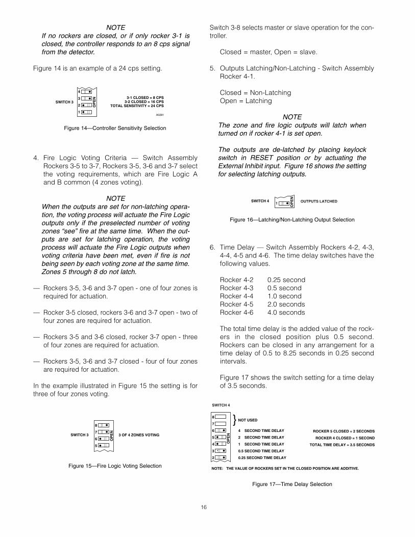
6. Time Delay — Switch Assembly Rockers 4-2, 4-3,4-4, 4-5 and 4-6. The time delay switches have thefollowing values.
Rocker 4-2 0.25 secondRocker 4-3 0.5 secondRocker 4-4 1.0 secondRocker 4-5 2.0 secondsRocker 4-6 4.0 seconds
The total time delay is the added value of the rock-ers in the closed position plus 0.5 second.Rockers can be closed in any arrangement for atime delay of 0.5 to 8.25 seconds in 0.25 secondintervals.
Figure 17 shows the switch setting for a time delayof 3.5 seconds.
16
4
3
2
1
OP
EN 3-1 CLOSED = 8 CPS
3-2 CLOSED = 16 CPSTOTAL SENSITIVITY = 24 CPS
SWITCH 3
A0281
Figure 14—Controller Sensitivity Selection
8
7
6
5
3 OF 4 ZONES VOTINGSWITCH 3
OP
EN
Figure 15—Fire Logic Voting Selection
OP
EN
SWITCH 4 OUTPUTS LATCHED1
Figure 16—Latching/Non-Latching Output Selection
8
7
6
5
4
3
2
OP
EN
NOTE: THE VALUE OF ROCKERS SET IN THE CLOSED POSITION ARE ADDITIVE.
4 SECOND TIME DELAY
2 SECOND TIME DELAY
1 SECOND TIME DELAY
0.5 SECOND TIME DELAY
0.25 SECOND TIME DELAY
NOT USED
ROCKER 5 CLOSED = 2 SECONDS
ROCKER 4 CLOSED = 1 SECOND
TOTAL TIME DELAY = 3.5 SECONDS
SWITCH 4
Figure 17—Time Delay Selection

It is inadvisable to use the minimum time delay (0.5second) with the maximum detector sensitivity (8cps), as this setting increases the possibility offalse system actuation.
CONTROLLER ELECTRICAL CONNECTIONS
All electrical connections are made to the plug-in fieldwiring connector that is furnished with the controller.Figure 18 shows its terminal configuration. Table 2 liststhe terminal connections and a brief description of theirusage.
Up to four detectors in four separate zones can be con-nected to the controller. Terminals A, B and D on thedetectors must be connected to the appropriate A, Band D terminals at the R7404 Controller. Connect theshield of the B-lead to terminal C in the detector and theother end to circuit ground (terminal 2) at the controller(see Figures 18 and 19). Terminal D in each detectorconnects directly to individual terminals 12 through 19 onthe controller.
17 95-8256
1
2
3
4
5
6
7
8
9
10
11
12
13
14
15
16
17
18
19
20
21
22
23
24
25
26
27
28
29
30
31
32
+ –
(A) +290 VDC
B - INPUT 1
B - INPUT 2
B - INPUT 3
B - INPUT 4
B - INPUT 5
B - INPUT 6
B - INPUT 7
B - INPUT 8
D1-1 oi DRIVER
D1-2 oi DRIVER
D1-3 oi DRIVER
D1-4 oi DRIVER
D1-5 oi DRIVER
D1-6 oi DRIVER
D1-7 oi DRIVER
D1-8 oi DRIVER
DATA OUTPUT 0
DATA OUTPUT 1
DATA OUTPUT 2
DATA OUTPUT 3
DATA OUTPUT 4
DATA OUTPUT 5
DATA OUTPUT 6
DATA OUTPUT 7
DMA OUT AVAILABLE
DMA OUT
DMA IN
DATA STROBE
DMA IN AVAILABLE
ZONE OUTPUT 1
ZONE OUTPUT 2
ZONE OUTPUT 3
ZONE OUTPUT 4
NOT USED
NOT USED
LOW LEVEL ALARM
LOCKOUT OUTPUT
FIRE LOGIC
DATA SYNC
ALARM OUTPUT
EXTERNAL INHIBIT
OUTPUTS INHIBITED
FAULT OUTPUT
EXTERNAL ACCEPT
STATUS & DET. OUTPUT S1
STATUS & DET. OUTPUT S2
STATUS & DET. OUTPUT S3
STATUS & DET. OUTPUT S4
STATUS & DET. OUTPUT S5
STATUS & DET. OUTPUT S6
STATUS & DET. OUTPUT S7
STATUS & DET. OUTPUT S8
DATA BUS 0
DATA BUS 1
DATA BUS 2
DATA BUS 3
DATA BUS 4
DATA BUS 5
DATA BUS 6
DATA BUS 7
CHASSIS (EARTH) GND
33
34
35
36
37
38
39
40
41
42
43
44
45
46
47
48
49
50
51
52
53
54
55
56
57
58
59
60
61
62
63
64
J2R7404J1
10 TO 38 VDC
Figure 18—R7404 Nuclear Surveillance ControllerTerminal Configuration
ElectricalTerminals
Description
1 and 2 Input power: +10 to +38 vdc (1 to positive, 2to circuit ground).
3 A-lead: (+290 vdc) connected to all detectors.
4 through 11 B-lead: input from each detector.
12 through 19 D- lead: oi driver to each detector.
20 through 27 Data Bus terminals - data transfer outputs,connected to the data input bus of the (next)surveillance controller in the series.
28 through 32 DMA (direct memory access) and data strobeterminals. DMA IN (terminal 30) is connectedto the data sync output of the last surveillancecontroller in the series.
33 through 36 Solid State Zone Outputs: correspond to fourfire zones (reference to ground - terminal 2).
NOTE: All R7404 solid state outputs are rated100 ma at 0.5 volt when “on” (low state). Theoutputs are high impedance (open collector,100K ohm) when “off” (high state). Only theFault output is normally “on.”
37, 38 Not used.
39 Low level alarm output – count rate hasexceeded 50% of sensitivity setting.
40 Solid state “lockout” output – activated by con-troller to indicate saturation lockout condition.
41 Solid State Fire Logic output – see “Theory ofOperation.”
42 Data Sync output – connects to DMA IN ofslave controller.
43 Solid State Alarm output – activated wheneverany zone output is activated. It is a latchingoutput and can be deactivated by depressingthe TEST/ACCEPT button or by activating theexternal accept input (see below).
44 External Inhibit (input) – when activated, resetsthe controller and disables fire response out-puts. Input is activated when shorted toground (-V, terminal 2).
45 Solid State Outputs Inhibited (output) – is acti-vated when fire response outputs are disabled.
46 Solid State Fault output – Normally “on” (lowvoltage - logic 1), turned off by controller toindicate a fault status.
47 External Accept (input) provides a means todeactivate the alarm output. Input is activatedwhen shorted to ground.
48 through 55 Solid State Status and Detector outputs – pro-vide binary representations of the front paneldigital displays for zone and status identifica-tion. Tables 3 and 4 list the identificationcodes and the logic states of the “Fault” and“Outputs Inhibited” bits for the various statusconditions.
56 through 63 Data Bus terminals – data transfer inputs, con-nected to the data output bus of the last sur-veillance controller in the series.
64 Chassis (earth) ground – should be connectedto circuit ground (terminal 2) through a 0.47 µF400 Volt non-polarized capacitor (not supplied).
Table 2—Nuclear Surveillance Controller Terminal Connections

TYPICAL SYSTEM APPLICATION
The following application is an example only. For assis-tance in adapting a system to your individual require-ments, contact Application Engineering at DetectorElectronics.
The system illustrated in Figure 19 incorporates two con-trollers that monitor eight detectors.
STARTUP PROCEDURE
CAUTIONSecure output loads before startup as describedin the “Manual Check in Normal Mode” subsec-tion of the “Checkout Procedure.”
1. After setting the selection switches and making allelectrical connections, make sure that power is offand plug controllers into connectors.
2. Turn on power and go through checkout proce-dures.
3. If the controllers appear to be operating normally,remove mechanical blocking devices and restorepower to the extinguishing loads.
CHECKOUT PROCEDURE
MANUAL CHECK OF OPTICAL INTEGRITY
1. Place keylock switch in TEST position.
2. FAULT LED turns on.
3. INHIBIT LED turns on.
4. ZONE display indicates the zone selected.DETECTOR display shows a “0”.
5. STATUS display indicates a “1”. (If any other num-ber appears, see “Troubleshooting” section.)
6. Push and hold TEST/ACCEPT button. If the lens isclean, a ZONE OUTPUT LED flashes to indicate thezone of the detector being tested (after time delay).
7. Appropriate FIRE LOGIC LEDs are turned on if vot-ing requirements are met.
(Surveillance zones 5-8 are not voted on and willnot turn on FIRE LOGIC LEDs).
8. Release TEST/ACCEPT button, ZONE OUTPUTLED remains on steady.
9. Push SELECT button. Controller sequences to thenext lower numbered zone.
10.Repeat steps 6 through 10 until all detectors havebeen checked.
18
ZoneStatus Outputs
S1 S2 S3 S4
1 1 0 0 02 0 1 0 03 1 1 0 04 0 0 1 05 1 0 1 06 0 1 1 07 1 1 1 08 0 0 0 1
Table 3—Relationship of ZONE Display to theStatus Outputs Table 4—Relationship of SYSTEM STATUS Display
to Status Outputs
Front Panel Display Status Outputs
OutputsSystem Status S5 S6 S7 S8 Fault Inhibited
0 0 0 0 0 0 1
1 0 1 0 0 0 1
2 0 0 1 0 0 0
3 0 1 1 0 x*** 0
4 0 0 0 1 0 0
5 0 1 0 1 0 0
6* 0 0 1 1 1 0
7** 0 1 1 1 1 0
8 0 or 1 0 0 0 0 1
9 1 1 0 0 0 1
Status Outputs Logic 0 = 100k ohms to ground (0 volts)S1 – S8, Fault Logic 1 = Less than 25 ohms to ground
Outputs Inhibited (0 volts)
Fire Zones onlySurveillance Zones only1 on Fire Zones, 0 on Surveillance Zones
***
***

19 95-8256
1 2 3 4 5 6 7 8 9 10 11 12 13 14 15 16 17 18 19 20 21 22 23 24 25 26 27 28 29 30 31 32
+ – (A) +
290 V
DC
B - IN
PUT 1
B - IN
PUT 2
B - IN
PUT 3
B - IN
PUT 4
B - IN
PUT 5
B - IN
PUT 6
B - IN
PUT 7
B - IN
PUT 8
D1-1
o i DR
IVER
D1-2
o i DR
IVER
D1-3
o i DR
IVER
D1-4
o i DR
IVER
D1-5
o i DR
IVER
D1-6
o i DR
IVER
D1-7
o i DR
IVER
D1-8
o i DR
IVER
DATA
OUT
PUT 0
DATA
OUT
PUT 1
DATA
OUT
PUT 2
DATA
OUT
PUT 3
DATA
OUT
PUT 4
DATA
OUT
PUT 5
DATA
OUT
PUT 6
DATA
OUT
PUT 7
DMA
OUT A
VAILA
BLE
DMA
OUT
DMA
IN
DATA
STR
OBE
DMA
IN A
VAILA
BLE
ZONE
OUT
PUT 1
ZONE
OUT
PUT 2
ZONE
OUT
PUT 3
ZONE
OUT
PUT 4
NOT U
SED
NOT U
SED
LOW
LEVE
L ALA
RM
LOCK
OUT O
UTPU
T
FIRE
LOGI
C
DATA
SYN
C
ALAR
M OU
TPUT
EXTE
RNAL
INHI
BIT
OUTP
UTS
INHI
BITE
D
FAUL
T OUT
PUT
EXTE
RNAL
ACC
EPT
STAT
US &
DET
. OUT
PUT S
1
STAT
US &
DET
. OUT
PUT S
2
STAT
US &
DET
. OUT
PUT S
3
STAT
US &
DET
. OUT
PUT S
4
STAT
US &
DET
. OUT
PUT S
5
STAT
US &
DET
. OUT
PUT S
6
STAT
US &
DET
. OUT
PUT S
7
STAT
US &
DET
. OUT
PUT S
8
DATA
BUS
0
DATA
BUS
1
DATA
BUS
2
DATA
BUS
3
DATA
BUS
4
DATA
BUS
5
DATA
BUS
6
DATA
BUS
7
CHAS
SIS
(EAR
TH) G
ND
33 34 35 36 37 38 39 40 41 42 43 44 45 46 47 48 49 50 51 52 53 54 55 56 57 58 59 60 61 62 63 64J2MA
STER
CON
TROL
LER
J1
10 TO
38 V
DC
1 2 3 4 5 6 7 8 9 10 11 12 13 14 15 16 17 18 19 20 21 22 23 24 25 26 27 28 29 30 31 32
+ – (A) +
290 V
DC
B - IN
PUT 1
B - IN
PUT 2
B - IN
PUT 3
B - IN
PUT 4
B - IN
PUT 5
B - IN
PUT 6
B - IN
PUT 7
B - IN
PUT 8
D1-1
o i DR
IVER
D1-2
o i DR
IVER
D1-3
o i DR
IVER
D1-4
o i DR
IVER
D1-5
o i DR
IVER
D1-6
o i DR
IVER
D1-7
o i DR
IVER
D1-8
o i DR
IVER
DATA
OUT
PUT 0
DATA
OUT
PUT 1
DATA
OUT
PUT 2
DATA
OUT
PUT 3
DATA
OUT
PUT 4
DATA
OUT
PUT 5
DATA
OUT
PUT 6
DATA
OUT
PUT 7
DMA
OUT A
VAILA
BLE
DMA
OUT
DMA
IN
DATA
STR
OBE
DMA
IN A
VAILA
BLE
ZONE
OUT
PUT 1
ZONE
OUT
PUT 2
ZONE
OUT
PUT 3
ZONE
OUT
PUT 4
NOT U
SED
NOT U
SED
LOW
LEVE
L ALA
RM
LOCK
OUT O
UTPU
T
FIRE
LOGI
C
DATA
SYN
C
ALAR
M OU
TPUT
EXTE
RNAL
INHI
BIT
OUTP
UTS
INHI
BITE
D
FAUL
T OUT
PUT
EXTE
RNAL
ACC
EPT
STAT
US &
DET
. OUT
PUT S
1
STAT
US &
DET
. OUT
PUT S
2
STAT
US &
DET
. OUT
PUT S
3
STAT
US &
DET
. OUT
PUT S
4
STAT
US &
DET
. OUT
PUT S
5
STAT
US &
DET
. OUT
PUT S
6
STAT
US &
DET
. OUT
PUT S
7
STAT
US &
DET
. OUT
PUT S
8
DATA
BUS
0
DATA
BUS
1
DATA
BUS
2
DATA
BUS
3
DATA
BUS
4
DATA
BUS
5
DATA
BUS
6
DATA
BUS
7
CHAS
SIS
(EAR
TH) G
ND
33 34 35 36 37 38 39 40 41 42 43 44 45 46 47 48 49 50 51 52 53 54 55 56 57 58 59 60 61 62 63 64J2SL
AVE
CONT
ROLL
ERJ1
10 TO
38 V
DC
A B1 C D1 A B5 C D5 A B2 C D2 A B6 C D6 A B3 C D3 A B7 C D7 A B4 C D4 A B8 C D8
A B1 C D1 A B5 C D5 A B2 C D2 A B6 C D6 A B3 C D3 A B7 C D7 A B4 C D4 A B8 C D8
C705
1
C705
1
C705
1
C705
1
C705
1
C705
1
C705
1
C705
1
3 4 * 12 3 8 * 16 3 5 * 13 3 9 * 17 3 6 * 14 3 10 * 18 3 7 * 15 3 11 * 19
A B1 B2 B3 B4 B5 B6 B7 B8 D1 D2 D3 D4 D5 D6 D7 D8
A B1 B2 B3 B4 B5 B6 B7 B8 D1 D2 D3 D4 D5 D6 D7 D8
56 57 58 59 60 61 62 63
20 21 22 23 24 25 26 27
3 4 * 12 3 8 * 16 3 5 * 13 3 9 * 17 3 6 * 14 3 10 * 18 3 7 * 15 3 11 * 19
*ALL
"C" L
EADS
ARE
CON
NECT
ED TO
CON
TROL
LER
GRO
UND
VIA
CABL
E SH
IELD
0.47
µF
/400
VC
APA
CIT
OR
0.47
µF
/400
VC
APA
CIT
OR
Fig
ure
19—
Typi
cal S
yste
m A
pplic
atio
n

TESTING OF DETECTOR MODULE RESPONSE TOUV RADIATION (COUNT MODE TEST)
1. Place keylock switch in TEST position.
2. SYSTEM STATUS displays the number “1”.
3. ZONE display shows the zone that is electricallypositioned for testing.
4. Press and release SELECT and TEST/ACCEPT but-tons simultaneously.
5. SYSTEM STATUS display changes to an “8”.
6. Press and hold TEST/ACCEPT button.
7. UV source tube (in detector housing of the moduleunder test) turns on.
8. Upper displays indicate the discharge rate of thesensor under test (in cps). If FIRE LOGIC LEDsturn on, multiply displayed count by 10. Countrate should be between 50 and 300 cps. If not,clean the window (fire detector module) and themetal oi reflector ring. If count rate does not fallwithin the 50 to 300 cps range after cleaning,and the oi ring shows no signs of deterioration,replace the sensor tube module. Record countreading in the Recommended Test Form (insideback cover).
9. Release TEST/ACCEPT button.
10.Upper displays now indicate quiescent state ofdetector tube. Count should be between 00 and05. If higher, place an obstruction over the detec-tor window. If the count rate returns to the 00 to 05range, the detector has been responding to exter-nal radiation. Check area for external source of UVradiation, and either remove it or shield the detec-tor from it. If none can be found, use cardboard tocover the windows of the detectors in the zonebeing tested. If the high count rate continues afterthe detector window is covered, this indicates afaulty module, and it must be replaced. If otherdetectors in the vicinity exhibit similar symptoms,the presence of x-rays or gamma radiation is indi-cated.
11.To test the next detector, press and release theSELECT button.
12.ZONE display shows zone just tested.
13.Press and release the SELECT button again.
14.Controller cycles to next lower zone pair (controllercycles through the detectors selected on rockerswitches 1-1 to 1-4). (See “Theory of Operation.”)
15.Repeat steps 6 through 14 until all detectors havebeen checked. At the completion of the sequence,each detector will have been tested for the follow-ing conditions:
A. Influence of background radiation, if any.
B. UV transmission capability of all optical surfaces(where applicable).
C. Calibration of UV source/UV detector (these ele-ments are factory adjusted, but are subject toinfluences that may affect the calibration).
D. If the system is to be tested for response to anactual fire, the exact response of each detectorcan be measured. If any improvements in systemlayout are needed, they will be revealed in thisway.
16.After completion of all tests, return keylock switchto NORMAL position. System resets and both dig-ital displays should become blank.
NOTEThe Automatic oi system continuously monitorsthe operation of the R7404 but does not monitorexternal relays or equipment that may be operat-ed from the fire signal outputs, the alarm signaloutput or the fault signal output. It is importantthat the system be manually checked using theNormal Mode Checkout Procedure on a regularbasis. The whole system (including externalequipment) should be checked periodically usingthe W8066 UV Test Lamp or an equivalent UVsource to simulate a fire.
MANUAL CHECK IN NORMAL MODE
The whole system should be periodically checked withthe W8066 UV Test Lamp or an equivalent UV source tomake sure that the detectors are not obstructed, that thearea “seen” by the detector has not changed, and thatthere is no fault in the oi circuit.
CAUTIONSecure output loads (remove power from valves,relays, igniters or other devices which would nor-mally be actuated by the UV system) before per-forming the following test.
20

1. Place the keylock switch in the NORMAL position.
2. Turn on W8066 UV Test Lamp or an equivalent UVsource and shine into any fire detector.
3. If system works correctly, the appropriate ZONEOUTPUT LED turns on and flashes, indicating thezone in which the detector is located. ZONE dis-play shows first zone activated. STATUS displayshows a “6”.
4. The FIRE LOGIC LEDs turn on if voting require-ments are met.
5. Turn off the UV source.
6. FIRE LOGIC LEDs stay on if turned on in step 4.
7. The ZONE OUTPUT LED stays on but stops flash-ing. The numeral indicating the first zone thatresponded to the UV signal is held in the ZONEdisplay, and the numeral “6” remains in the STATUSdisplay.
8. Repeat steps 2 through 5 for each detector in thesystem.
9. After all detectors have been checked, reset thesystem by turning the keylock switch to the RESETposition. Then turn it to the NORMAL position.Display turns off. INHIBIT LED turns off. FAULTLED turns off.
10.Restore power to output loads or remove anymechanical blocking devices.
TROUBLESHOOTING
The Automatic Fault Identification circuitry, in conjunctionwith the Automatic oi feature, continuously monitors thestatus of the controller and all detectors. In the event ofa system malfunction, the microprocessor immediatelybranches to an automatic fault identification program. Ifa fault occurs, the FAULT LED will turn on. If the fault isin the detector or wiring, the ZONE display will indicatewhich zone has the fault. The STATUS display will indi-cate by code number the type of fault. If the fault is inthe microprocessor circuitry, the displays will remainblank but the FAULT LED will turn on. See Table 5 for adetailed explanation of the status/fault code numbers onthe lower digital display and the corresponding identifi-cation numbers on the upper digital display.
NOTERecord all faults on the Fault Record Sheet at theback of this manual.
VOLTAGES AND WAVEFORMS TO AID INTROUBLESHOOTING
A-lead (terminal 3) to circuit ground: +290 vdc.D-lead (terminals 12 through 19) to A-lead: less than 1volt.
Do not check in normal mode. System must be in testmode to prevent false actuation. In the test mode, man-ual oi operation can be verified by observing the voltagebetween the D-lead and circuit ground.
Due to the meter “loading” factor, the voltage from the D-lead to ground measures approximately +260 vdc.When the test button is depressed (in test mode) the volt-age on the D-lead of the detector under test drops to 0.5vdc or less (see Figure 20).
B-lead (terminals 4 through 11): The manual oi testcauses the detector to send a series of voltage pulses tothe controller. The waveform on the B-lead of the detec-tor under test is illustrated in Figure 21.
SOLID STATE INPUT AND OUTPUT CIRCUITRY
Figures 22 and 23 illustrate the input and output drive cir-cuitry of the R7404 Controller.
ORDERING INFORMATION
When ordering specify:
Model R7404 Fire Protection and Nuclear SurveillanceController
Model C7051 Detector
Number of C7051 Detectors and R7404 Controllers
ACCESSORIES
— Q4004 Mounting Cage. Cage accommodates upto eight modules. It is designed to fit a standard 19inch instrument rack. See form 95-8241 for details.
— Filler panels (part number 002188-001). For emptypositions in the Q4004 Cage.
— W8066 Explosion-proof, portable UV Test Lamp.See form 95-8345 for details.
— Matched pair, DE1888G2 sensor tubes (part num-ber 003240-207), for replacement into C7051Detector.
21 95-8256

DEVICE REPAIR
For devices or components in need of repair, contactyour local source or return the equipment transportationprepaid to:
Detector Electronics CorporationReturned Goods Department6901 West 110th StreetMinneapolis, Minnesota 55438 U.S.A.
22
Upper Displays Lower DisplayDescription
Detector Zone Status
0 0 0 Keylock switch is in RESET position, or the external inhibit is activated.(Outputs inhibited, except Status outputs.)
0 1 - 8 1 Keylock switch is in TEST position. (Outputs inhibited, except Status outputs.)
0 1 - 8 2 oi fault - the oi ring and/or the window of the detector indicated in the upper ZONEdisplay is dirty, or the detector module has lost sensitivity, or there is an open wirebetween the detector and the controller.
0 1 - 8 3 Zones 1-4: Count rate has exceeded 50% of sensitivity setting. A separate outputis activated, and no fault output is activated.
Zones 5-8: Runaway detector – fault output activated. (This can be checked byusing the count mode test of the controller as described in the “Checkout” section.)
0 0 4 Low +290 vdc caused by a shorted A-lead or controller malfunction.
0 0 5 High +290 vdc caused by a failure in the regulating network in the controller.
0 1 - 4 6 Fire Output signal - blinking ZONE OUTPUT LED indicates fire location. SteadyZONE OUTPUT LED indicates that the detectors in that zone have responded to aUV signal, but are no longer responding. This is not a fault condition.
0 1 - 8 7 Count Subtraction Lockout. Surveillance detector module or modules are discharg-ing at their maximum rate and the controller is subtracting the maximum signal fromthe fire detector module’s signal. The system is thus “saturated,” and effectively“locked-out,” i.e. there will be no false actuation of the system due to interferencesignals, but the system is incapable of responding if a fire should occur at this time.A separate output is activated when the system enters “lock-out.”
0 1 - 8 8 Controller has been placed in “count” mode (see “Checkout” section). Pushing andreleasing both SELECT and TEST/ACCEPT buttons at the same time while the key-lock switch is in the TEST position changes the lower display to a numeral “8” - thecount mode for checking the count rate of each zone.
Blank Blank 9 Data Link Failure – slave controller is not receiving data, or is receiving incorrectdata from the master controller.
Blank Blank Blank FAULT LED on. There is a problem in the R7404 microprocessor circuitry. Place key-lock switch in RESET, push and release LAMP TEST pushbutton and return the key-lock switch to NORMAL. If operation does not return to normal, replace the entireunit. Make sure the new R7404 is programmed the same as the one being replaced.
Blank Blank Blank No LEDs on or displays on. Check input power to controller or blown fuse in con-troller.
Table 5—Status Codes - Nuclear Surveillance Controller

23 95-8256
TESTBUTTON
PRESSED
TESTBUTTON
RELEASED
–0 V
+260 VDC
Figure 20—Detector D-lead Voltage - Manual Test
5 to 10 mS
5 uS
0 V
+ 40 V
Figure 21—Detector B-lead Waveform
D
S
G
100 K Ω
+VDC60 VOLT MAXIMUM(MUST BE EXTERNALLYPROVIDED)
LOAD
OUTPUT CIRCUIT
+VDC
LOAD
100 K ΩSWITCH
EQUIVALENT CIRCUIT
Figure 22—R7404 Solid State Output Circuit
+VDC
10K
Figure 23—Solid State Input
Detector Electronics Corporation6901 West 110th Street • Minneapolis, Minnesota 55438 • Fax (612) 829-8750
Telephone (612) 941-5665 or (800) 765-FIRE • www.detronics.com • email: [email protected]

24
Fault Record Sheet
Upper Display Lower DisplayDate Time
Detector Zone System StatusOperator Comments

25 95-8256
Recommended Test FormDate Date Date Lens Sensitivity Readings
RemarksInstalled Checked Cleaned Count Test Mode