Embed Size (px)
Citation preview

May 2010 Doc ID 17028 Rev 1 1/43
UM0900User manual
1 kW 3-phase motor control demonstration board featuringIGBT intelligent power module STGIPL14K60 STEVAL-IHM025V1
1 Introduction
This document describes the 1 kW 3-phase motor control demonstration board featuring the IGBT intelligent power module STGIPL14K60. The demonstration board is an AC-DC inverter that generates a 3-phase waveform for driving 3- or 2-phase motors such as induction motors or PMSM motors up to 1000 W, with or without sensors.
The main device presented in this user manual is a universal, fully evaluated and populated design consisting of a 3-phase inverter bridge based on the 600 V IGBT power module in the SDIP 38L package mounted on heatsink. STGIPL14K60 integrates: high voltage, short-circuit rugged IGBT and high voltage gate drivers with advanced features like integrated op-amp suitable for advanced current sensing. Thanks to this integrated module, the system has been specifically designed to achieve power inversion in a reliable and compact design. The system architecture of the module based on integrated advanced features is specifically designed to achieve an accurate and fast conditioning of the current feedback therefore matching the typical requirements in field oriented control (FOC).
The board is designed to be compatible with single-phase mains, supplying from 90 VAC to 285 VAC or from 125 VDC up to 400 VDC for DC voltage.
This document is associated with the release of the demonstration board STEVAL-IHM025V1 (see Figure 1 below).
Figure 1. STEVAL-IHM025V1
www.st.com
Contents UM0900
2/43 Doc ID 17028 Rev 1
Contents
1 Introduction . . . . . . . . . . . . . . . . . . . . . . . . . . . . . . . . . . . . . . . . . . . . . . . . 1
2 System introduction . . . . . . . . . . . . . . . . . . . . . . . . . . . . . . . . . . . . . . . . . 6
2.1 Main characteristics . . . . . . . . . . . . . . . . . . . . . . . . . . . . . . . . . . . . . . . . . . 6
2.2 Target application . . . . . . . . . . . . . . . . . . . . . . . . . . . . . . . . . . . . . . . . . . . . 6
2.3 Safety and operating instructions . . . . . . . . . . . . . . . . . . . . . . . . . . . . . . . . 7
2.3.1 General terms . . . . . . . . . . . . . . . . . . . . . . . . . . . . . . . . . . . . . . . . . . . . . 7
2.3.2 Demonstration board intended use . . . . . . . . . . . . . . . . . . . . . . . . . . . . . 7
2.3.3 Demonstration board installation . . . . . . . . . . . . . . . . . . . . . . . . . . . . . . . 7
2.3.4 Electrical connections . . . . . . . . . . . . . . . . . . . . . . . . . . . . . . . . . . . . . . . 8
3 Board description . . . . . . . . . . . . . . . . . . . . . . . . . . . . . . . . . . . . . . . . . . . 9
3.1 System architecture . . . . . . . . . . . . . . . . . . . . . . . . . . . . . . . . . . . . . . . . . . 9
3.2 The board schematic . . . . . . . . . . . . . . . . . . . . . . . . . . . . . . . . . . . . . . . . 10
3.3 Circuit description . . . . . . . . . . . . . . . . . . . . . . . . . . . . . . . . . . . . . . . . . . . 15
3.3.1 Power supply . . . . . . . . . . . . . . . . . . . . . . . . . . . . . . . . . . . . . . . . . . . . . 15
3.3.2 Inrush limitation . . . . . . . . . . . . . . . . . . . . . . . . . . . . . . . . . . . . . . . . . . . 15
3.3.3 Power block based on IGBT module . . . . . . . . . . . . . . . . . . . . . . . . . . . 15
3.3.4 Brake function . . . . . . . . . . . . . . . . . . . . . . . . . . . . . . . . . . . . . . . . . . . . 16
3.3.5 Overcurrent protection . . . . . . . . . . . . . . . . . . . . . . . . . . . . . . . . . . . . . . 16
3.3.6 Current sensing amplifying network . . . . . . . . . . . . . . . . . . . . . . . . . . . . 17
3.3.7 The tachometer and hall/encoder inputs . . . . . . . . . . . . . . . . . . . . . . . . 21
3.3.8 Temperature feedback and overtemperature protection (OTP) . . . . . . . 22
4 Hardware setting of the STEVAL-IHM025V1 . . . . . . . . . . . . . . . . . . . . . 23
4.1 Hardware settings for six-step (block commutation) current control - single-shunt configuration . . . . . . . . . . . . . . . . . . . . . . . . . . . . . . . . . . . 23
4.2 Hardware settings with three-shunt configuration . . . . . . . . . . . . . . . . . . 24
5 Description of jumpers, test pins and connectors . . . . . . . . . . . . . . . . 25
6 Connector placement . . . . . . . . . . . . . . . . . . . . . . . . . . . . . . . . . . . . . . . 29
7 Bill of materials . . . . . . . . . . . . . . . . . . . . . . . . . . . . . . . . . . . . . . . . . . . . 30
UM0900 Contents
Doc ID 17028 Rev 1 3/43
8 PCB layout . . . . . . . . . . . . . . . . . . . . . . . . . . . . . . . . . . . . . . . . . . . . . . . . 34
9 Ordering information . . . . . . . . . . . . . . . . . . . . . . . . . . . . . . . . . . . . . . . 38
10 Using the STEVAL-IHM025V1 with STM32 FOC firmware library . . . . 38
10.1 Environmental considerations . . . . . . . . . . . . . . . . . . . . . . . . . . . . . . . . . 38
10.2 Hardware requirements . . . . . . . . . . . . . . . . . . . . . . . . . . . . . . . . . . . . . . 39
10.3 Software requirements . . . . . . . . . . . . . . . . . . . . . . . . . . . . . . . . . . . . . . . 39
10.4 Software modifications . . . . . . . . . . . . . . . . . . . . . . . . . . . . . . . . . . . . . . . 39
11 Conclusion . . . . . . . . . . . . . . . . . . . . . . . . . . . . . . . . . . . . . . . . . . . . . . . . 41
12 References . . . . . . . . . . . . . . . . . . . . . . . . . . . . . . . . . . . . . . . . . . . . . . . . 41
13 Revision history . . . . . . . . . . . . . . . . . . . . . . . . . . . . . . . . . . . . . . . . . . . 42
List of tables UM0900
4/43 Doc ID 17028 Rev 1
List of tables
Table 1. Current reading configuration - gain settings . . . . . . . . . . . . . . . . . . . . . . . . . . . . . . . . . . . 21Table 2. Jumper settings for PMSM or generic AC motor - six-step. . . . . . . . . . . . . . . . . . . . . . . . . 23Table 3. Jumper settings for PMSM or generic AC motor - three shunt . . . . . . . . . . . . . . . . . . . . . . 24Table 4. Jumper description . . . . . . . . . . . . . . . . . . . . . . . . . . . . . . . . . . . . . . . . . . . . . . . . . . . . . . . 25Table 5. Connector pinout description . . . . . . . . . . . . . . . . . . . . . . . . . . . . . . . . . . . . . . . . . . . . . . . 26Table 6. Testing pins description . . . . . . . . . . . . . . . . . . . . . . . . . . . . . . . . . . . . . . . . . . . . . . . . . . . 28Table 7. Bill of materials . . . . . . . . . . . . . . . . . . . . . . . . . . . . . . . . . . . . . . . . . . . . . . . . . . . . . . . . . . 30Table 8. Document revision history . . . . . . . . . . . . . . . . . . . . . . . . . . . . . . . . . . . . . . . . . . . . . . . . . 42
UM0900 List of figures
Doc ID 17028 Rev 1 5/43
List of figures
Figure 1. STEVAL-IHM025V1 . . . . . . . . . . . . . . . . . . . . . . . . . . . . . . . . . . . . . . . . . . . . . . . . . . . . . . . 1Figure 2. Motor control system architecture. . . . . . . . . . . . . . . . . . . . . . . . . . . . . . . . . . . . . . . . . . . . . 9Figure 3. STEVAL-IHM025V1 schematic - part 1 . . . . . . . . . . . . . . . . . . . . . . . . . . . . . . . . . . . . . . . 10Figure 4. STEVAL-IHM025V1 schematic - part 2 . . . . . . . . . . . . . . . . . . . . . . . . . . . . . . . . . . . . . . . 11Figure 5. STEVAL-IHM025V1 schematic - part 3 . . . . . . . . . . . . . . . . . . . . . . . . . . . . . . . . . . . . . . . 12Figure 6. STEVAL-IHM025V1 schematic - part 4 . . . . . . . . . . . . . . . . . . . . . . . . . . . . . . . . . . . . . . . 13Figure 7. STEVAL-IHM025V1 schematic - part 5 . . . . . . . . . . . . . . . . . . . . . . . . . . . . . . . . . . . . . . . 14Figure 8. Power supply block diagram. . . . . . . . . . . . . . . . . . . . . . . . . . . . . . . . . . . . . . . . . . . . . . . . 15Figure 9. Overcurrent protection . . . . . . . . . . . . . . . . . . . . . . . . . . . . . . . . . . . . . . . . . . . . . . . . . . . . 17Figure 10. Three-shunt configuration. . . . . . . . . . . . . . . . . . . . . . . . . . . . . . . . . . . . . . . . . . . . . . . . . . 19Figure 11. Six-step current sensing configuration . . . . . . . . . . . . . . . . . . . . . . . . . . . . . . . . . . . . . . . . 21Figure 12. STEVAL-IHM025V1 connector placement . . . . . . . . . . . . . . . . . . . . . . . . . . . . . . . . . . . . . 29Figure 13. Copper tracks - top side . . . . . . . . . . . . . . . . . . . . . . . . . . . . . . . . . . . . . . . . . . . . . . . . . . . 34Figure 14. Copper tracks - bottom side . . . . . . . . . . . . . . . . . . . . . . . . . . . . . . . . . . . . . . . . . . . . . . . . 35Figure 15. Silk screen - top side . . . . . . . . . . . . . . . . . . . . . . . . . . . . . . . . . . . . . . . . . . . . . . . . . . . . . 36Figure 16. Silk screen - bottom side . . . . . . . . . . . . . . . . . . . . . . . . . . . . . . . . . . . . . . . . . . . . . . . . . . 37
System introduction UM0900
6/43 Doc ID 17028 Rev 1
2 System introduction
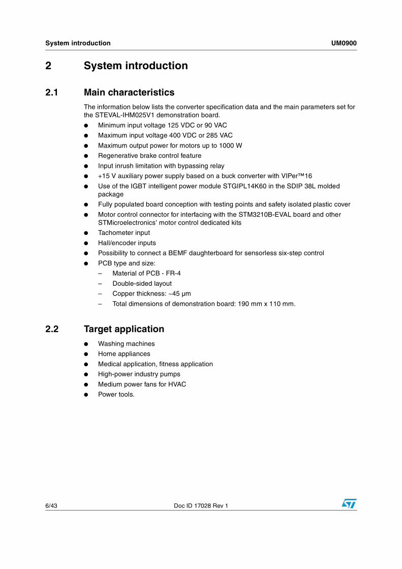
2.1 Main characteristicsThe information below lists the converter specification data and the main parameters set for the STEVAL-IHM025V1 demonstration board.
● Minimum input voltage 125 VDC or 90 VAC
● Maximum input voltage 400 VDC or 285 VAC
● Maximum output power for motors up to 1000 W
● Regenerative brake control feature
● Input inrush limitation with bypassing relay
● +15 V auxiliary power supply based on a buck converter with VIPer™16
● Use of the IGBT intelligent power module STGIPL14K60 in the SDIP 38L molded package
● Fully populated board conception with testing points and safety isolated plastic cover
● Motor control connector for interfacing with the STM3210B-EVAL board and other STMicroelectronics’ motor control dedicated kits
● Tachometer input
● Hall/encoder inputs
● Possibility to connect a BEMF daughterboard for sensorless six-step control
● PCB type and size:
– Material of PCB - FR-4
– Double-sided layout
– Copper thickness: ~45 µm
– Total dimensions of demonstration board: 190 mm x 110 mm.
2.2 Target application ● Washing machines
● Home appliances
● Medical application, fitness application
● High-power industry pumps
● Medium power fans for HVAC
● Power tools.
UM0900 System introduction
Doc ID 17028 Rev 1 7/43
2.3 Safety and operating instructions
2.3.1 General terms
Warning: During assembly, testing, and normal operation, the demonstration board poses several inherent hazards, including bare wires, moving or rotating parts and hot surfaces. There is a danger of serious personal injury if the kit or components are improperly used or incorrectly installed. The kit is not electrically isolated from the AC/DC input. The demonstration board is directly linked to the mains voltage. No insulation is ensured between accessible parts and high voltage. All measuring equipment must be isolated from the mains before powering the board. When using an oscilloscope with the demonstration board, it must be isolated from the AC line. This prevents shock from occurring as a result of touching any single point in the circuit, but does not prevent shock when touching two or more points in the circuit. Do not touch the demonstration board after disconnection from the voltage supply; several parts and power terminals, which contain energized capacitors, must be allowed to discharge.
All operations involving transportation, installation and use, as well as maintenance, are to be carried out by skilled technical personnel (national accident prevention rules must be observed). For the purpose of these basic safety instructions, “skilled technical personnel” are considered as suitably qualified people who are familiar with the installation, use, and maintenance of power electronic systems.
2.3.2 Demonstration board intended use
The STEVAL-IHM025V1 demonstration board is designed for demonstration purposes only and must not be used in final applications. The technical data, as well as information concerning the power supply conditions, must only be taken from the relevant documentation and must be strictly observed.
2.3.3 Demonstration board installation
The installation and cooling of the demonstration board must be in accordance with the specifications and the targeted application.
● The motor drive converters must be protected against excessive strain. In particular, no components are to be bent or isolating distances altered during the course of transportation or handling.
● No contact must be made with other electronic components and contacts.
● The boards contain electro-statically sensitive components that are prone to damage through improper use. Electrical components must not be mechanically damaged or destroyed.
System introduction UM0900
8/43 Doc ID 17028 Rev 1
2.3.4 Electrical connections
Applicable national accident prevention rules must be followed when working on the main power supply. The electrical installation must be carried out in accordance with the appropriate requirements.
A system architecture which supplies power to the demonstration board must be equipped with additional control and protective devices in accordance with the applicable safety requirements (e.g. compliance with technical equipment and accident prevention rules).
UM0900 Board description
Doc ID 17028 Rev 1 9/43
3 Board description
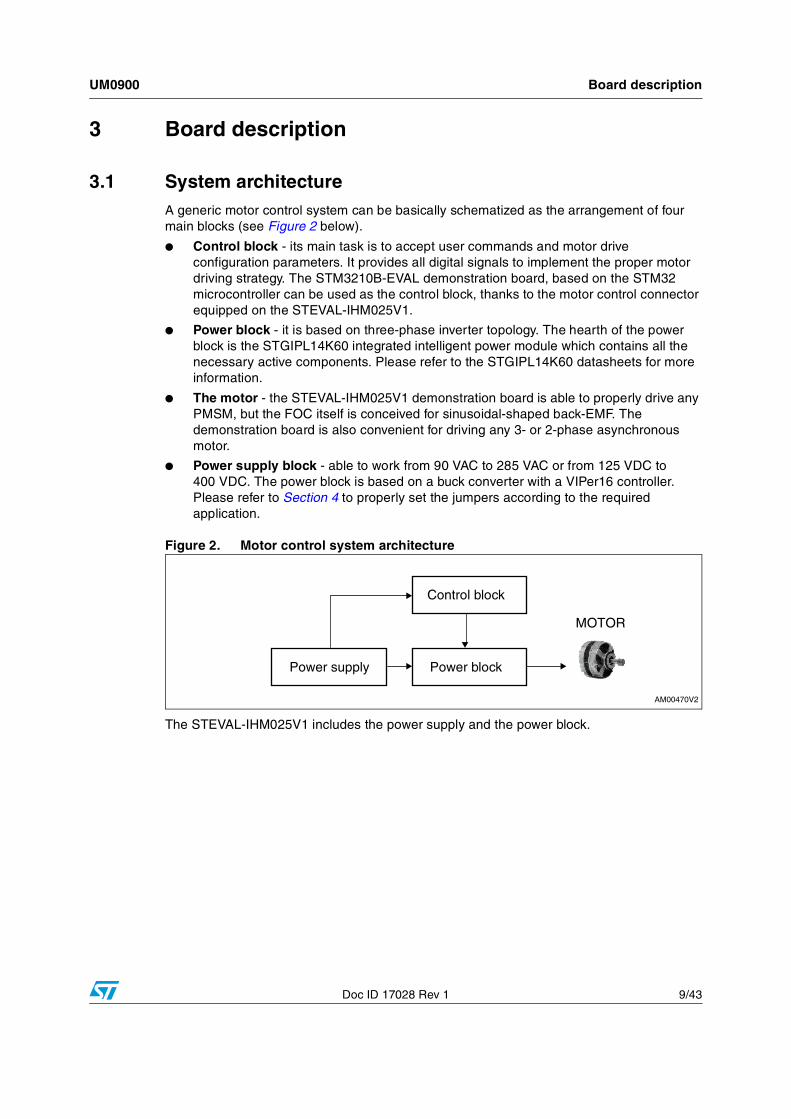
3.1 System architectureA generic motor control system can be basically schematized as the arrangement of four main blocks (see Figure 2 below).
● Control block - its main task is to accept user commands and motor drive configuration parameters. It provides all digital signals to implement the proper motor driving strategy. The STM3210B-EVAL demonstration board, based on the STM32 microcontroller can be used as the control block, thanks to the motor control connector equipped on the STEVAL-IHM025V1.
● Power block - it is based on three-phase inverter topology. The hearth of the power block is the STGIPL14K60 integrated intelligent power module which contains all the necessary active components. Please refer to the STGIPL14K60 datasheets for more information.
● The motor - the STEVAL-IHM025V1 demonstration board is able to properly drive any PMSM, but the FOC itself is conceived for sinusoidal-shaped back-EMF. The demonstration board is also convenient for driving any 3- or 2-phase asynchronous motor.
● Power supply block - able to work from 90 VAC to 285 VAC or from 125 VDC to 400 VDC. The power block is based on a buck converter with a VIPer16 controller. Please refer to Section 4 to properly set the jumpers according to the required application.
Figure 2. Motor control system architecture
The STEVAL-IHM025V1 includes the power supply and the power block.
Board description UM0900
10/43 Doc ID 17028 Rev 1
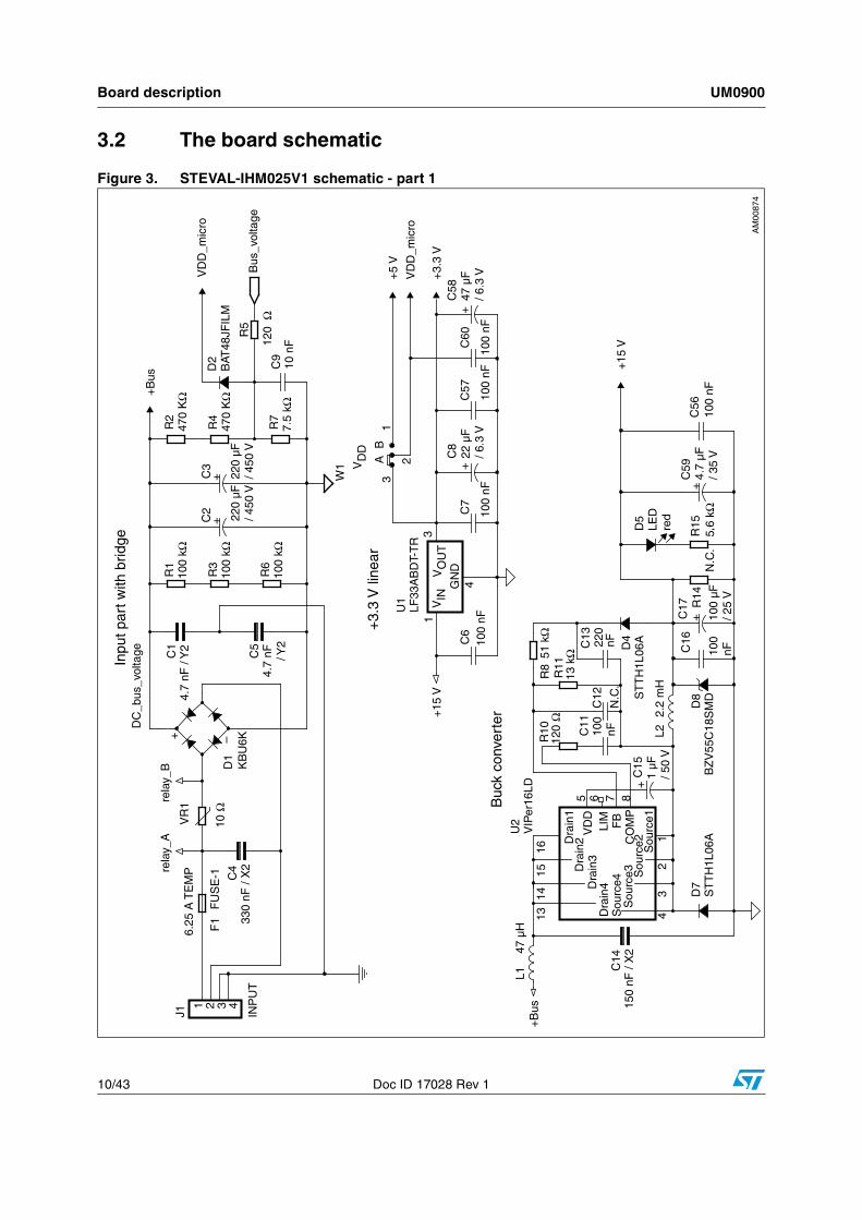
3.2 The board schematic
Figure 3. STEVAL-IHM025V1 schematic - part 1

UM0900 Board description
Doc ID 17028 Rev 1 11/43
Figure 4. STEVAL-IHM025V1 schematic - part 2
Board description UM0900
12/43 Doc ID 17028 Rev 1
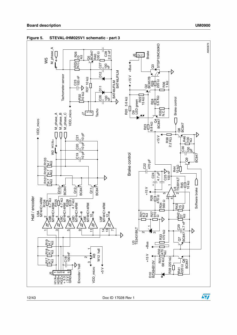
Figure 5. STEVAL-IHM025V1 schematic - part 3
UM0900 Board description
Doc ID 17028 Rev 1 13/43
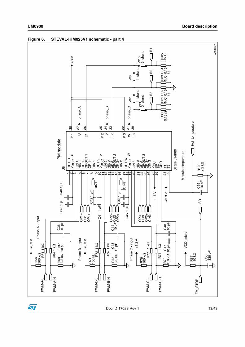
Figure 6. STEVAL-IHM025V1 schematic - part 4
Board description UM0900
14/43 Doc ID 17028 Rev 1
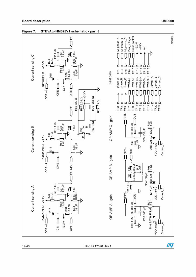
Figure 7. STEVAL-IHM025V1 schematic - part 5
UM0900 Board description
Doc ID 17028 Rev 1 15/43
3.3 Circuit description
3.3.1 Power supply
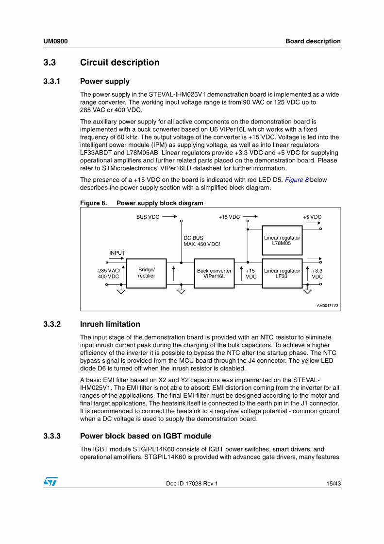
The power supply in the STEVAL-IHM025V1 demonstration board is implemented as a wide range converter. The working input voltage range is from 90 VAC or 125 VDC up to 285 VAC or 400 VDC.
The auxiliary power supply for all active components on the demonstration board is implemented with a buck converter based on U6 VIPer16L which works with a fixed frequency of 60 kHz. The output voltage of the converter is +15 VDC. Voltage is fed into the intelligent power module (IPM) as supplying voltage, as well as into linear regulators LF33ABDT and L78M05AB. Linear regulators provide +3.3 VDC and +5 VDC for supplying operational amplifiers and further related parts placed on the demonstration board. Please refer to STMicroelectronics’ VIPer16LD datasheet for further information.
The presence of a +15 VDC on the board is indicated with red LED D5. Figure 8 below describes the power supply section with a simplified block diagram.
Figure 8. Power supply block diagram
3.3.2 Inrush limitation
The input stage of the demonstration board is provided with an NTC resistor to eliminate input inrush current peak during the charging of the bulk capacitors. To achieve a higher efficiency of the inverter it is possible to bypass the NTC after the startup phase. The NTC bypass signal is provided from the MCU board through the J4 connector. The yellow LED diode D6 is turned off when the inrush resistor is disabled.
A basic EMI filter based on X2 and Y2 capacitors was implemented on the STEVAL-IHM025V1. The EMI filter is not able to absorb EMI distortion coming from the inverter for all ranges of the applications. The final EMI filter must be designed according to the motor and final target applications. The heatsink itself is connected to the earth pin in the J1 connector. It is recommended to connect the heatsink to a negative voltage potential - common ground when a DC voltage is used to supply the demonstration board.
3.3.3 Power block based on IGBT module
The IGBT module STGIPL14K60 consists of IGBT power switches, smart drivers, and operational amplifiers. STGPIL14K60 is provided with advanced gate drivers, many features
Board description UM0900
16/43 Doc ID 17028 Rev 1
are available like: integrated op-amp for signal conditioning, integrated comparators for overcurrent or short-circuit protection, and the “SMART SHUTDOWN” function. Please refer to the STGIPL14K60 datasheets for more information.
3.3.4 Brake function
A hardware brake feature is implemented on the STEVAL-IHM025V1 demonstration board. This feature connects the external dummy load applied to the J6 connector to the bus, to eliminate overvoltage generated while the motor acts as a generator. Voltage on the bus is sensed through a voltage divider net, with R32, R33 and R42 resistors, and it is compared to the voltage reference built around the precise voltage reference U3. The brake dummy load is switched on when voltage on the bus reaches 445 VDC and is switched off when the voltage falls below 420 VDC. The brake function can be activated by the microcontroller thanks to the motor-control connector (please set the W3 jumper in position “A”). The brake threshold levels can be modified by calculating R32, R33, R42 and R45 new values.
3.3.5 Overcurrent protection
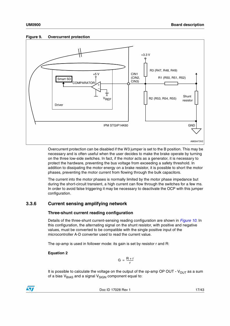
Hardware overcurrent protection (OCP) is implemented on the board. STGIPL14K60 integrates three internal comparators. Thanks to the internal connection between the comparator output and shutdown block (see Figure 9), the intervention time of overcurrent protection is extremely low, ranging slightly above 200 ns (Smart Shutdown).
The overcurrent protection acts as soon as the voltage on the CIN pin rises above the internal voltage reference (typical value is 0.53 V). Considering the default value of the shunt resistor, it follows that the maximum allowed current is equal to:
Equation 1
Note: R3 is not connected on the STEVAL-IHM025V1.
With the default values this gives:
● ISHUNT_MAX = 7 A
ISHUNT MAX
VREF
RSHUNT---------------------- 1 R1
R2--------+⎝ ⎠
⎛ ⎞×=
UM0900 Board description
Doc ID 17028 Rev 1 17/43
Figure 9. Overcurrent protection
Overcurrent protection can be disabled if the W3 jumper is set to the B position. This may be necessary and is often useful when the user decides to make the brake operate by turning on the three low-side switches. In fact, if the motor acts as a generator, it is necessary to protect the hardware, preventing the bus voltage from exceeding a safety threshold. In addition to dissipating the motor energy on a brake resistor, it is possible to short the motor phases, preventing the motor current from flowing through the bulk capacitors.
The current into the motor phases is normally limited by the motor phase impedance but during the short-circuit transient, a high current can flow through the switches for a few ms. In order to avoid false triggering it may be necessary to deactivate the OCP with this jumper configuration.
3.3.6 Current sensing amplifying network
Three-shunt current reading configuration
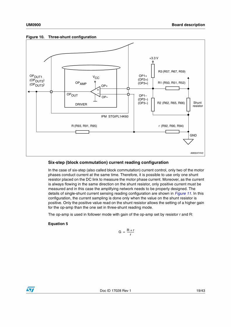
Details of the three-shunt current-sensing reading configuration are shown in Figure 10. In this configuration, the alternating signal on the shunt resistor, with positive and negative values, must be converted to be compatible with the single positive input of the microcontroller A-D converter used to read the current value.
The op-amp is used in follower mode: its gain is set by resistor r and R:
Equation 2
It is possible to calculate the voltage on the output of the op-amp OP OUT - VOUT as a sum of a bias VBIAS and a signal VSIGN component equal to:
G R r+r
------------=
Board description UM0900
18/43 Doc ID 17028 Rev 1
Equation 3
Total gain of the circuit including resistors' divider is equal to:
Equation 4
With the default values this gives:
● VBIAS = 1.7 V
● G = 4.3
● GTOT = 1.7
● Maximum current amplifiable without distortion is 6.5 A.
VOUT VSIGN VBIAS+=
VBIAS3.3
1R1-------- 1
R2-------- 1
R3--------+ +⎝ ⎠
⎛ ⎞ R3×---------------------------------------------------------- G×=
VSIGN
I RSHUNT×
1R1-------- 1
R2-------- 1
R3--------+ +⎝ ⎠
⎛ ⎞ R1×---------------------------------------------------------- G×=
GTOTVSIGN
VIN----------------
VSIGN
RSHUNT I×-----------------------------= =
UM0900 Board description
Doc ID 17028 Rev 1 19/43
Figure 10. Three-shunt configuration
Six-step (block commutation) current reading configuration
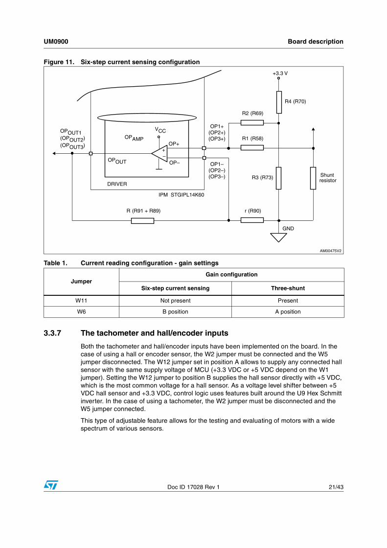
In the case of six-step (also called block commutation) current control, only two of the motor phases conduct current at the same time. Therefore, it is possible to use only one shunt resistor placed on the DC link to measure the motor phase current. Moreover, as the current is always flowing in the same direction on the shunt resistor, only positive current must be measured and in this case the amplifying network needs to be properly designed. The details of single-shunt current sensing reading configuration are shown in Figure 11. In this configuration, the current sampling is done only when the value on the shunt resistor is positive. Only the positive value read on the shunt resistor allows the setting of a higher gain for the op-amp than the one set in three-shunt reading mode.
The op-amp is used in follower mode with gain of the op-amp set by resistor r and R:
Equation 5
G R r+r
------------=
Board description UM0900
20/43 Doc ID 17028 Rev 1
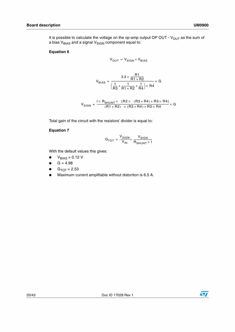
It is possible to calculate the voltage on the op-amp output OP OUT - VOUT as the sum of a bias VBIAS and a signal VSIGN component equal to:
Equation 6
Total gain of the circuit with the resistors' divider is equal to:
Equation 7
With the default values this gives:
● VBIAS = 0.12 V
● G = 4.98
● GTOT = 2.53
● Maximum current amplifiable without distortion is 6.5 A.
VOUT VSIGN VBIAS+=
VBIAS
3.3R1
R1 R2+----------------------×
1R3-------- 1
R1 R2+---------------------- 1
R4--------+ +⎝ ⎠
⎛ ⎞ R4×------------------------------------------------------------------------ G×=
VSIGN
I R× SHUNT × R2 × R3 R4+( ) R3 R4×+[ ]R1 R2+( ) R3 R4+( ) R3 R4×+×
-------------------------------------------------------------------------------------------------------------------------- G×=
GTOT
VSIGN
VIN----------------
VSIGN
RSHUNT I×-------------------------------==
UM0900 Board description
Doc ID 17028 Rev 1 21/43
Figure 11. Six-step current sensing configuration
3.3.7 The tachometer and hall/encoder inputs
Both the tachometer and hall/encoder inputs have been implemented on the board. In the case of using a hall or encoder sensor, the W2 jumper must be connected and the W5 jumper disconnected. The W12 jumper set in position A allows to supply any connected hall sensor with the same supply voltage of MCU (+3.3 VDC or +5 VDC depend on the W1 jumper). Setting the W12 jumper to position B supplies the hall sensor directly with +5 VDC, which is the most common voltage for a hall sensor. As a voltage level shifter between +5 VDC hall sensor and +3.3 VDC, control logic uses features built around the U9 Hex Schmitt inverter. In the case of using a tachometer, the W2 jumper must be disconnected and the W5 jumper connected.
This type of adjustable feature allows for the testing and evaluating of motors with a wide spectrum of various sensors.
Table 1. Current reading configuration - gain settings
JumperGain configuration
Six-step current sensing Three-shunt
W11 Not present Present
W6 B position A position

Board description UM0900
22/43 Doc ID 17028 Rev 1
3.3.8 Temperature feedback and overtemperature protection (OTP)
Hardware overtemperature protection is also implemented on the STEVAL-IHM025V1 demonstration board. This feature fully protects the IPM module against damage when the temperature on the junction on the IPM overruns a defined value. The temperature is sensed through an NTC resistor which is integrated into the IPM. The measured signal is fed through the J4 motor connector to the MCU control unit and can be read with an A-D converter. The signal is also fed to the U6 comparator where it is compared with a 2.5 V reference voltage which is built around U7 precision reference TS3431. The output signal of the U6 comparator is fed into the SD pin of the IPM to stop the commutation of the connected motor. With the value of the integrated NTC resistor inside the IPM and R100 resistor equal to 2.2kΩ, the shutdown temperature is roughly 85 °C.
UM0900 Hardware setting of the STEVAL-IHM025V1
Doc ID 17028 Rev 1 23/43
4 Hardware setting of the STEVAL-IHM025V1
The STEVAL-IHM025V1 demonstration board can be driven through the J4 motor connector by various control units released by STMicroelectronics. The demonstration board is suitable for field oriented control as well as for tachometer or hall sensor closed-loop control. The STEVAL-IHM025V1 demonstration board ideally fits with STMicroelectronics’ released STM3210B-EVAL board based on the STM32 MCU family as the control unit for FOC-driving algorithms.
4.1 Hardware settings for six-step (block commutation) current control - single-shunt configurationTo drive any motor, the user must ensure that:
● The motor control demonstration board is driven by a control board that provides the six output signals required to drive the 3-phase power stage
● The motor is connected to the J2 motor output connector
● If using an encoder or hall sensor connection, it is connected to connector J5
● If using a tachometer connection, it is connected to connector J7
● If using a dissipative hardware brake connection to a related dummy load, it is connected to connector J6.
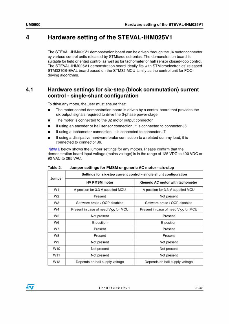
Table 2 below shows the jumper settings for any motors. Please confirm that the demonstration board input voltage (mains voltage) is in the range of 125 VDC to 400 VDC or 90 VAC to 285 VAC.
Table 2. Jumper settings for PMSM or generic AC motor - six-step
JumperSettings for six-step current control - single shunt configuration
HV PMSM motor Generic AC motor with tachometer
W1 A position for 3.3 V supplied MCU A position for 3.3 V supplied MCU
W2 Present Not present
W3 Software brake / OCP disabled Software brake / OCP disabled
W4 Present in case of need VDD for MCU Present in case of need VDD for MCU
W5 Not present Present
W6 B position B position
W7 Present Present
W8 Present Present
W9 Not present Not present
W10 Not present Not present
W11 Not present Not present
W12 Depends on hall supply voltage Depends on hall supply voltage
Hardware setting of the STEVAL-IHM025V1 UM0900
24/43 Doc ID 17028 Rev 1
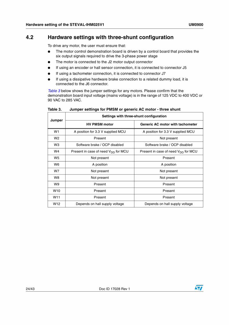
4.2 Hardware settings with three-shunt configurationTo drive any motor, the user must ensure that:
● The motor control demonstration board is driven by a control board that provides the six output signals required to drive the 3-phase power stage
● The motor is connected to the J2 motor output connector
● If using an encoder or hall sensor connection, it is connected to connector J5
● If using a tachometer connection, it is connected to connector J7
● If using a dissipative hardware brake connection to a related dummy load, it is connected to the J6 connector.
Table 3 below shows the jumper settings for any motors. Please confirm that the demonstration board input voltage (mains voltage) is in the range of 125 VDC to 400 VDC or 90 VAC to 285 VAC.
Table 3. Jumper settings for PMSM or generic AC motor - three shunt
JumperSettings with three-shunt configuration
HV PMSM motor Generic AC motor with tachometer
W1 A position for 3.3 V supplied MCU A position for 3.3 V supplied MCU
W2 Present Not present
W3 Software brake / OCP disabled Software brake / OCP disabled
W4 Present in case of need VDD for MCU Present in case of need VDD for MCU
W5 Not present Present
W6 A position A position
W7 Not present Not present
W8 Not present Not present
W9 Present Present
W10 Present Present
W11 Present Present
W12 Depends on hall supply voltage Depends on hall supply voltage
UM0900 Description of jumpers, test pins and connectors
Doc ID 17028 Rev 1 25/43
5 Description of jumpers, test pins and connectors
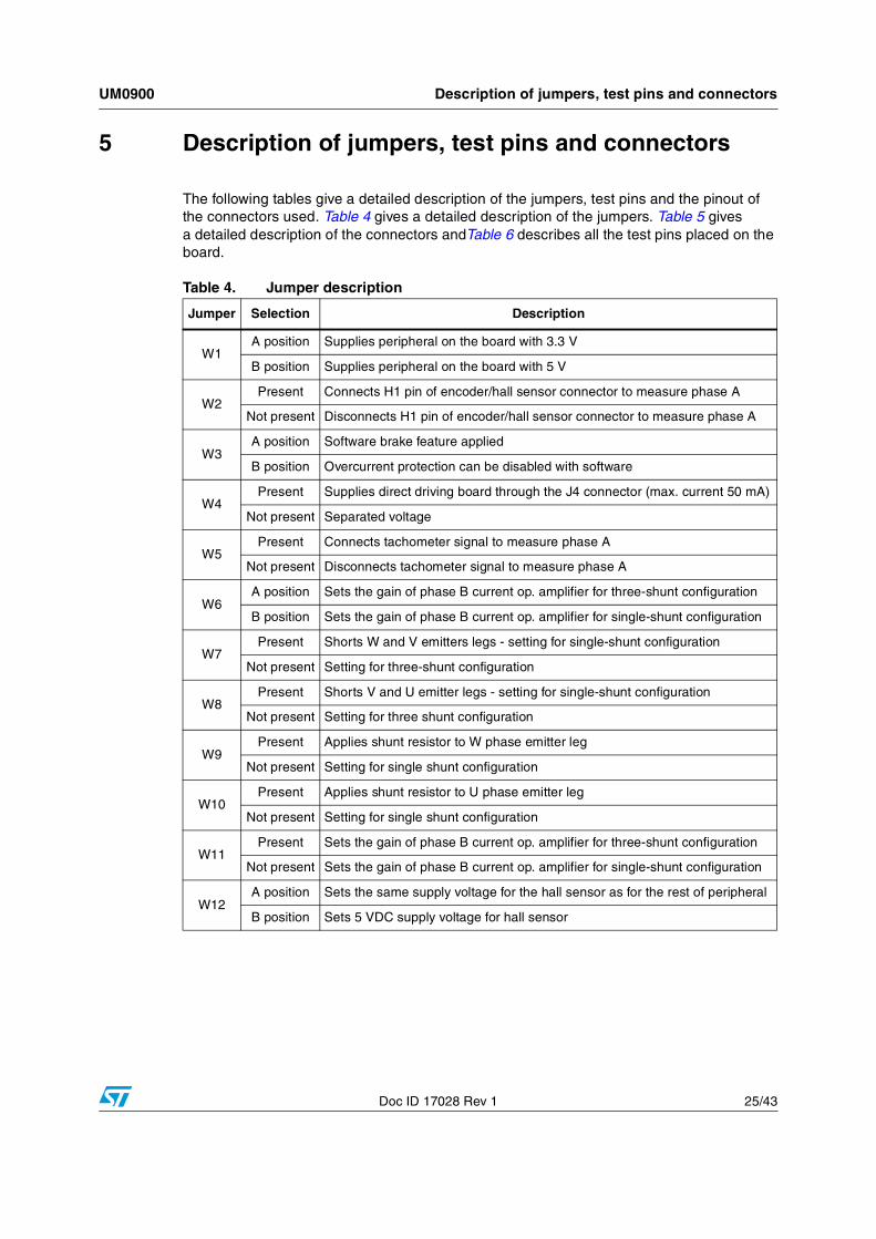
The following tables give a detailed description of the jumpers, test pins and the pinout of the connectors used. Table 4 gives a detailed description of the jumpers. Table 5 gives a detailed description of the connectors andTable 6 describes all the test pins placed on the board.
Table 4. Jumper description
Jumper Selection Description
W1A position Supplies peripheral on the board with 3.3 V
B position Supplies peripheral on the board with 5 V
W2Present Connects H1 pin of encoder/hall sensor connector to measure phase A
Not present Disconnects H1 pin of encoder/hall sensor connector to measure phase A
W3A position Software brake feature applied
B position Overcurrent protection can be disabled with software
W4Present Supplies direct driving board through the J4 connector (max. current 50 mA)
Not present Separated voltage
W5Present Connects tachometer signal to measure phase A
Not present Disconnects tachometer signal to measure phase A
W6A position Sets the gain of phase B current op. amplifier for three-shunt configuration
B position Sets the gain of phase B current op. amplifier for single-shunt configuration
W7Present Shorts W and V emitters legs - setting for single-shunt configuration
Not present Setting for three-shunt configuration
W8Present Shorts V and U emitter legs - setting for single-shunt configuration
Not present Setting for three shunt configuration
W9Present Applies shunt resistor to W phase emitter leg
Not present Setting for single shunt configuration
W10Present Applies shunt resistor to U phase emitter leg
Not present Setting for single shunt configuration
W11Present Sets the gain of phase B current op. amplifier for three-shunt configuration
Not present Sets the gain of phase B current op. amplifier for single-shunt configuration
W12A position Sets the same supply voltage for the hall sensor as for the rest of peripheral
B position Sets 5 VDC supply voltage for hall sensor
Description of jumpers, test pins and connectors UM0900
26/43 Doc ID 17028 Rev 1
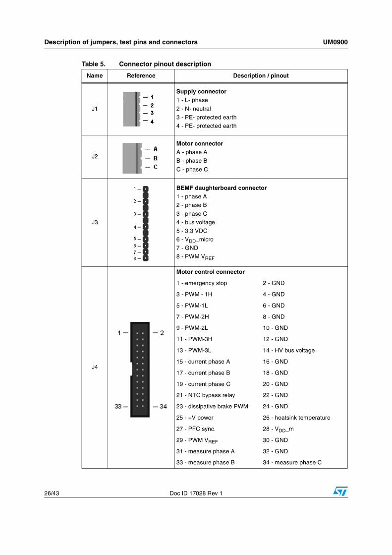
Table 5. Connector pinout description
Name Reference Description / pinout
J1
Supply connector1 - L- phase
2 - N- neutral
3 - PE- protected earth
4 - PE- protected earth
J2
Motor connectorA - phase A
B - phase B
C - phase C
J3
BEMF daughterboard connector1 - phase A
2 - phase B
3 - phase C
4 - bus voltage
5 - 3.3 VDC
6 - VDD_micro
7 - GND
8 - PWM VREF
J4
Motor control connector
1 - emergency stop 2 - GND
3 - PWM - 1H 4 - GND
5 - PWM-1L 6 - GND
7 - PWM-2H 8 - GND
9 - PWM-2L 10 - GND
11 - PWM-3H 12 - GND
13 - PWM-3L 14 - HV bus voltage
15 - current phase A 16 - GND
17 - current phase B 18 - GND
19 - current phase C 20 - GND
21 - NTC bypass relay 22 - GND
23 - dissipative brake PWM 24 - GND
25 - +V power 26 - heatsink temperature
27 - PFC sync. 28 - VDD_m
29 - PWM VREF 30 - GND
31 - measure phase A 32 - GND
33 - measure phase B 34 - measure phase C
UM0900 Description of jumpers, test pins and connectors
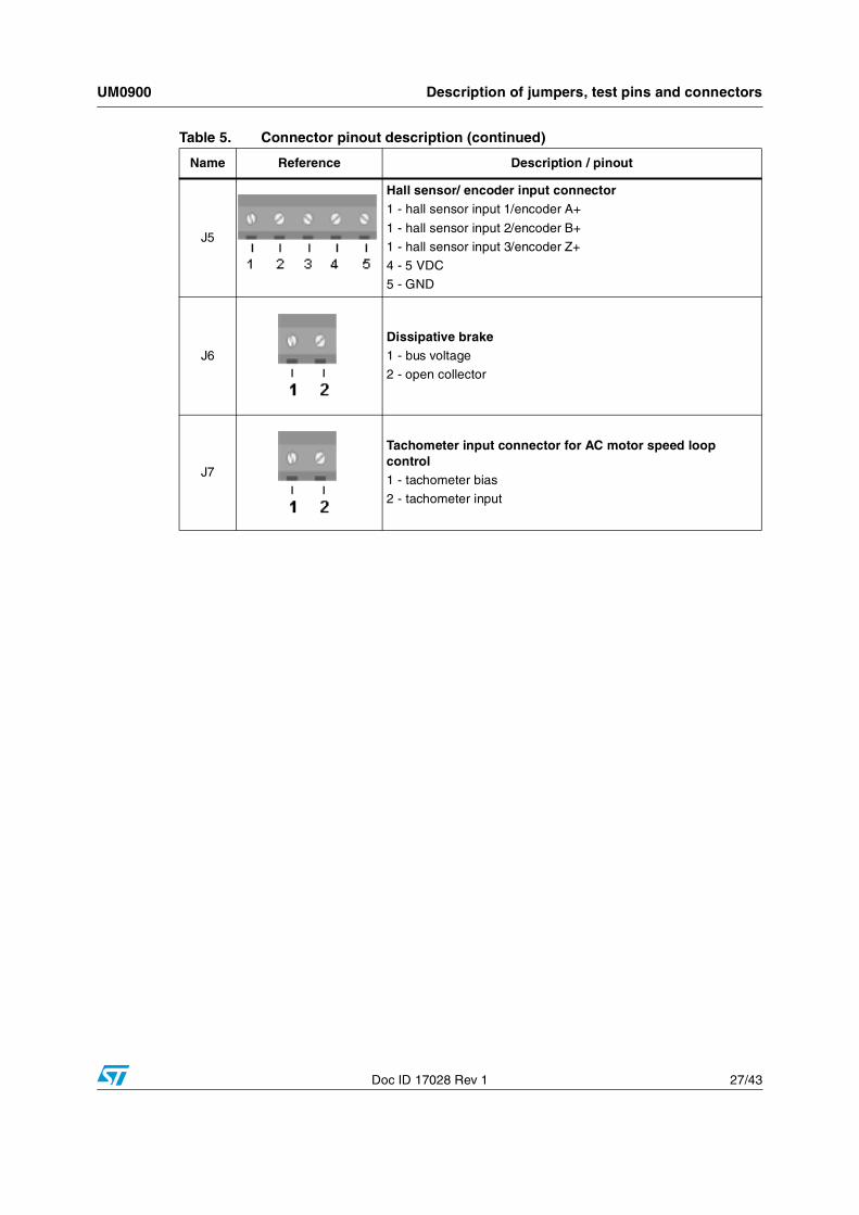
Doc ID 17028 Rev 1 27/43
J5
Hall sensor/ encoder input connector1 - hall sensor input 1/encoder A+
1 - hall sensor input 2/encoder B+
1 - hall sensor input 3/encoder Z+
4 - 5 VDC
5 - GND
J6
Dissipative brake1 - bus voltage
2 - open collector
J7
Tachometer input connector for AC motor speed loop control1 - tachometer bias
2 - tachometer input
Table 5. Connector pinout description (continued)
Name Reference Description / pinout
Description of jumpers, test pins and connectors UM0900
28/43 Doc ID 17028 Rev 1
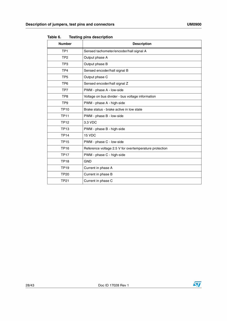
Table 6. Testing pins description
Number Description
TP1 Sensed tachometer/encoder/hall signal A
TP2 Output phase A
TP3 Output phase B
TP4 Sensed encoder/hall signal B
TP5 Output phase C
TP6 Sensed encoder/hall signal Z
TP7 PWM - phase A - low-side
TP8 Voltage on bus divider - bus voltage information
TP9 PWM - phase A - high-side
TP10 Brake status - brake active in low state
TP11 PWM - phase B - low-side
TP12 3.3 VDC
TP13 PWM - phase B - high-side
TP14 15 VDC
TP15 PWM - phase C - low-side
TP16 Reference voltage 2.5 V for overtemperature protection
TP17 PWM - phase C - high-side
TP18 GND
TP19 Current in phase A
TP20 Current in phase B
TP21 Current in phase C
UM0900 Connector placement
Doc ID 17028 Rev 1 29/43
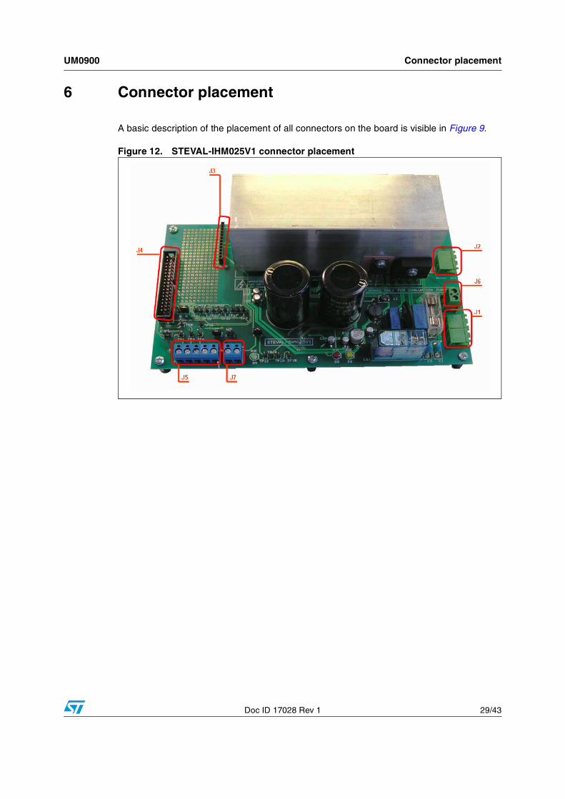
6 Connector placement
A basic description of the placement of all connectors on the board is visible in Figure 9.
Figure 12. STEVAL-IHM025V1 connector placement
Bill of materials UM0900
30/43 Doc ID 17028 Rev 1
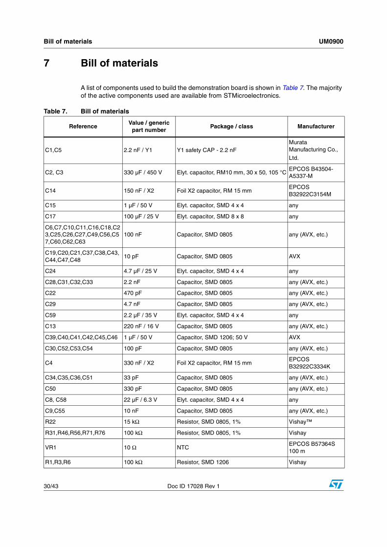
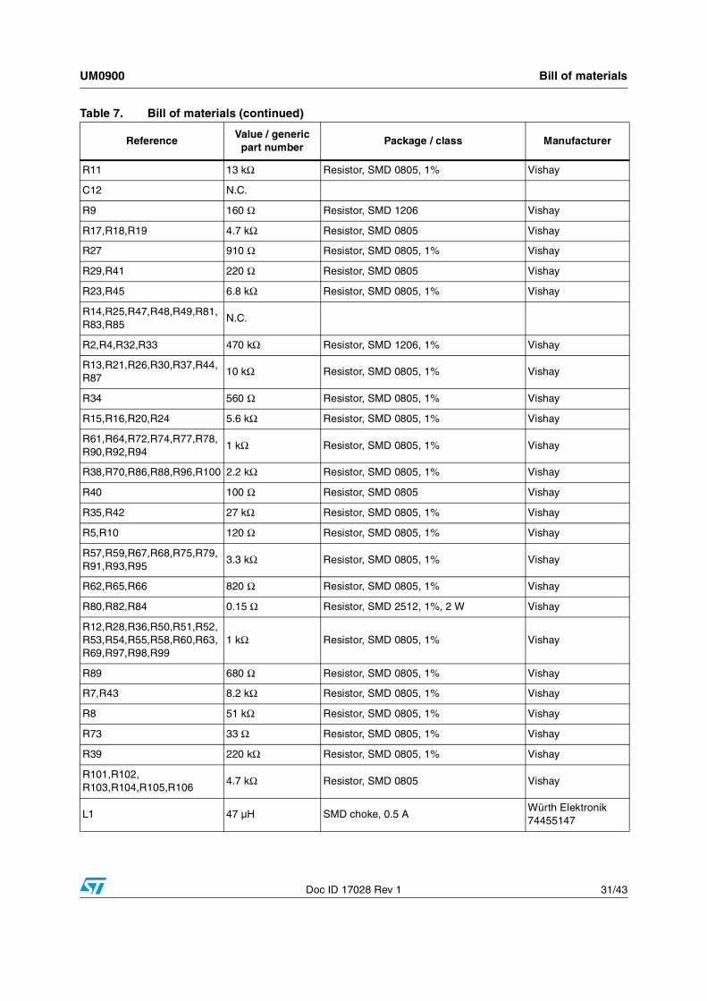
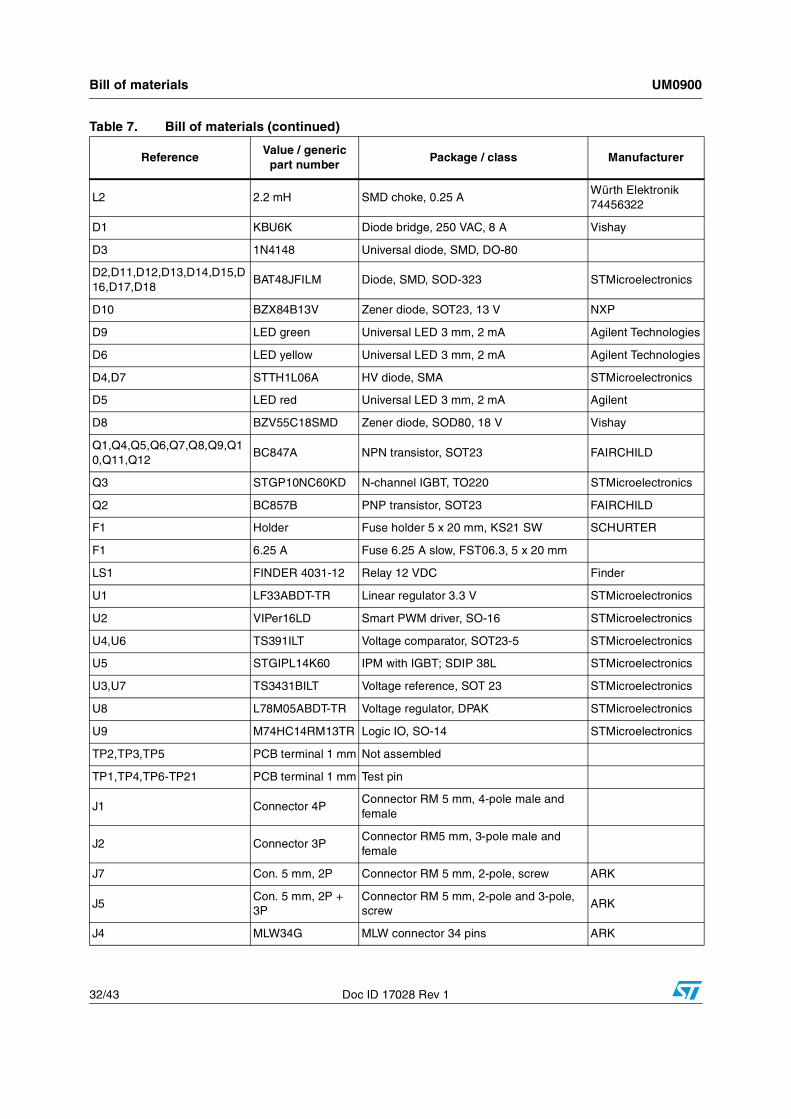
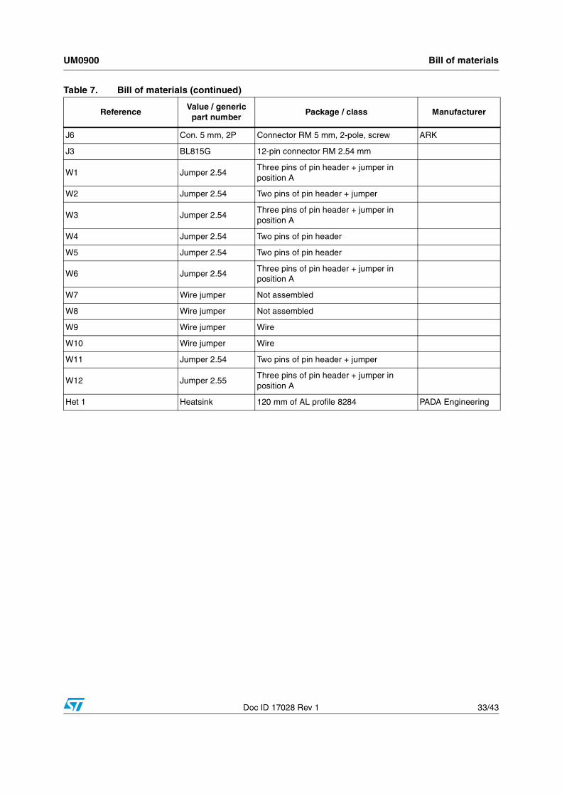
7 Bill of materials
A list of components used to build the demonstration board is shown in Table 7. The majority of the active components used are available from STMicroelectronics.
Table 7. Bill of materials
ReferenceValue / generic
part numberPackage / class Manufacturer
C1,C5 2.2 nF / Y1 Y1 safety CAP - 2.2 nFMurata Manufacturing Co.,
Ltd.
C2, C3 330 µF / 450 V Elyt. capacitor, RM10 mm, 30 x 50, 105 °CEPCOS B43504-A5337-M
C14 150 nF / X2 Foil X2 capacitor, RM 15 mmEPCOS B32922C3154M
C15 1 µF / 50 V Elyt. capacitor, SMD 4 x 4 any
C17 100 µF / 25 V Elyt. capacitor, SMD 8 x 8 any
C6,C7,C10,C11,C16,C18,C23,C25,C26,C27,C49,C56,C57,C60,C62,C63
100 nF Capacitor, SMD 0805 any (AVX, etc.)
C19,C20,C21,C37,C38,C43,C44,C47,C48
10 pF Capacitor, SMD 0805 AVX
C24 4.7 µF / 25 V Elyt. capacitor, SMD 4 x 4 any
C28,C31,C32,C33 2.2 nF Capacitor, SMD 0805 any (AVX, etc.)
C22 470 pF Capacitor, SMD 0805 any (AVX, etc.)
C29 4.7 nF Capacitor, SMD 0805 any (AVX, etc.)
C59 2.2 µF / 35 V Elyt. capacitor, SMD 4 x 4 any
C13 220 nF / 16 V Capacitor, SMD 0805 any (AVX, etc.)
C39,C40,C41,C42,C45,C46 1 µF / 50 V Capacitor, SMD 1206; 50 V AVX
C30,C52,C53,C54 100 pF Capacitor, SMD 0805 any (AVX, etc.)
C4 330 nF / X2 Foil X2 capacitor, RM 15 mmEPCOS B32922C3334K
C34,C35,C36,C51 33 pF Capacitor, SMD 0805 any (AVX, etc.)
C50 330 pF Capacitor, SMD 0805 any (AVX, etc.)
C8, C58 22 µF / 6.3 V Elyt. capacitor, SMD 4 x 4 any
C9,C55 10 nF Capacitor, SMD 0805 any (AVX, etc.)
R22 15 kΩ Resistor, SMD 0805, 1% Vishay™
R31,R46,R56,R71,R76 100 kΩ Resistor, SMD 0805, 1% Vishay
VR1 10 Ω NTCEPCOS B57364S 100 m
R1,R3,R6 100 kΩ Resistor, SMD 1206 Vishay
UM0900 Bill of materials
Doc ID 17028 Rev 1 31/43
R11 13 kΩ Resistor, SMD 0805, 1% Vishay
C12 N.C.
R9 160 Ω Resistor, SMD 1206 Vishay
R17,R18,R19 4.7 kΩ Resistor, SMD 0805 Vishay
R27 910 Ω Resistor, SMD 0805, 1% Vishay
R29,R41 220 Ω Resistor, SMD 0805 Vishay
R23,R45 6.8 kΩ Resistor, SMD 0805, 1% Vishay
R14,R25,R47,R48,R49,R81,R83,R85
N.C.
R2,R4,R32,R33 470 kΩ Resistor, SMD 1206, 1% Vishay
R13,R21,R26,R30,R37,R44,R87
10 kΩ Resistor, SMD 0805, 1% Vishay
R34 560 Ω Resistor, SMD 0805, 1% Vishay
R15,R16,R20,R24 5.6 kΩ Resistor, SMD 0805, 1% Vishay
R61,R64,R72,R74,R77,R78,R90,R92,R94
1 kΩ Resistor, SMD 0805, 1% Vishay
R38,R70,R86,R88,R96,R100 2.2 kΩ Resistor, SMD 0805, 1% Vishay
R40 100 Ω Resistor, SMD 0805 Vishay
R35,R42 27 kΩ Resistor, SMD 0805, 1% Vishay
R5,R10 120 Ω Resistor, SMD 0805, 1% Vishay
R57,R59,R67,R68,R75,R79,R91,R93,R95
3.3 kΩ Resistor, SMD 0805, 1% Vishay
R62,R65,R66 820 Ω Resistor, SMD 0805, 1% Vishay
R80,R82,R84 0.15 Ω Resistor, SMD 2512, 1%, 2 W Vishay
R12,R28,R36,R50,R51,R52,R53,R54,R55,R58,R60,R63,R69,R97,R98,R99
1 kΩ Resistor, SMD 0805, 1% Vishay
R89 680 Ω Resistor, SMD 0805, 1% Vishay
R7,R43 8.2 kΩ Resistor, SMD 0805, 1% Vishay
R8 51 kΩ Resistor, SMD 0805, 1% Vishay
R73 33 Ω Resistor, SMD 0805, 1% Vishay
R39 220 kΩ Resistor, SMD 0805, 1% Vishay
R101,R102, R103,R104,R105,R106
4.7 kΩ Resistor, SMD 0805 Vishay
L1 47 µH SMD choke, 0.5 AWürth Elektronik 74455147
Table 7. Bill of materials (continued)
ReferenceValue / generic
part numberPackage / class Manufacturer
Bill of materials UM0900
32/43 Doc ID 17028 Rev 1
L2 2.2 mH SMD choke, 0.25 AWürth Elektronik 74456322
D1 KBU6K Diode bridge, 250 VAC, 8 A Vishay
D3 1N4148 Universal diode, SMD, DO-80
D2,D11,D12,D13,D14,D15,D16,D17,D18
BAT48JFILM Diode, SMD, SOD-323 STMicroelectronics
D10 BZX84B13V Zener diode, SOT23, 13 V NXP
D9 LED green Universal LED 3 mm, 2 mA Agilent Technologies
D6 LED yellow Universal LED 3 mm, 2 mA Agilent Technologies
D4,D7 STTH1L06A HV diode, SMA STMicroelectronics
D5 LED red Universal LED 3 mm, 2 mA Agilent
D8 BZV55C18SMD Zener diode, SOD80, 18 V Vishay
Q1,Q4,Q5,Q6,Q7,Q8,Q9,Q10,Q11,Q12
BC847A NPN transistor, SOT23 FAIRCHILD
Q3 STGP10NC60KD N-channel IGBT, TO220 STMicroelectronics
Q2 BC857B PNP transistor, SOT23 FAIRCHILD
F1 Holder Fuse holder 5 x 20 mm, KS21 SW SCHURTER
F1 6.25 A Fuse 6.25 A slow, FST06.3, 5 x 20 mm
LS1 FINDER 4031-12 Relay 12 VDC Finder
U1 LF33ABDT-TR Linear regulator 3.3 V STMicroelectronics
U2 VIPer16LD Smart PWM driver, SO-16 STMicroelectronics
U4,U6 TS391ILT Voltage comparator, SOT23-5 STMicroelectronics
U5 STGIPL14K60 IPM with IGBT; SDIP 38L STMicroelectronics
U3,U7 TS3431BILT Voltage reference, SOT 23 STMicroelectronics
U8 L78M05ABDT-TR Voltage regulator, DPAK STMicroelectronics
U9 M74HC14RM13TR Logic IO, SO-14 STMicroelectronics
TP2,TP3,TP5 PCB terminal 1 mm Not assembled
TP1,TP4,TP6-TP21 PCB terminal 1 mm Test pin
J1 Connector 4PConnector RM 5 mm, 4-pole male and female
J2 Connector 3PConnector RM5 mm, 3-pole male and female
J7 Con. 5 mm, 2P Connector RM 5 mm, 2-pole, screw ARK
J5Con. 5 mm, 2P + 3P
Connector RM 5 mm, 2-pole and 3-pole, screw
ARK
J4 MLW34G MLW connector 34 pins ARK
Table 7. Bill of materials (continued)
ReferenceValue / generic
part numberPackage / class Manufacturer
UM0900 Bill of materials
Doc ID 17028 Rev 1 33/43
J6 Con. 5 mm, 2P Connector RM 5 mm, 2-pole, screw ARK
J3 BL815G 12-pin connector RM 2.54 mm
W1 Jumper 2.54Three pins of pin header + jumper in position A
W2 Jumper 2.54 Two pins of pin header + jumper
W3 Jumper 2.54Three pins of pin header + jumper in position A
W4 Jumper 2.54 Two pins of pin header
W5 Jumper 2.54 Two pins of pin header
W6 Jumper 2.54Three pins of pin header + jumper in position A
W7 Wire jumper Not assembled
W8 Wire jumper Not assembled
W9 Wire jumper Wire
W10 Wire jumper Wire
W11 Jumper 2.54 Two pins of pin header + jumper
W12 Jumper 2.55Three pins of pin header + jumper in position A
Het 1 Heatsink 120 mm of AL profile 8284 PADA Engineering
Table 7. Bill of materials (continued)
ReferenceValue / generic
part numberPackage / class Manufacturer
PCB layout UM0900
34/43 Doc ID 17028 Rev 1
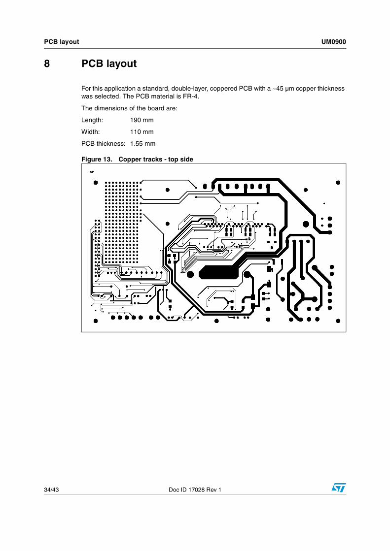
8 PCB layout
For this application a standard, double-layer, coppered PCB with a ~45 µm copper thickness was selected. The PCB material is FR-4.
The dimensions of the board are:
Length: 190 mm
Width: 110 mm
PCB thickness: 1.55 mm
Figure 13. Copper tracks - top side
UM0900 PCB layout
Doc ID 17028 Rev 1 35/43
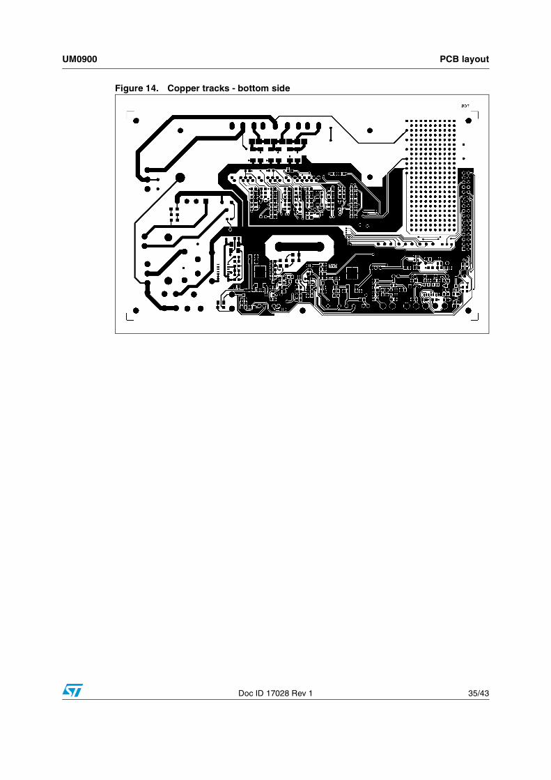
Figure 14. Copper tracks - bottom side
PCB layout UM0900
36/43 Doc ID 17028 Rev 1
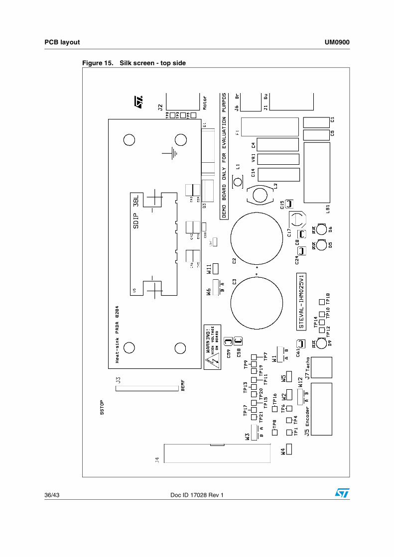
Figure 15. Silk screen - top side
UM0900 PCB layout
Doc ID 17028 Rev 1 37/43
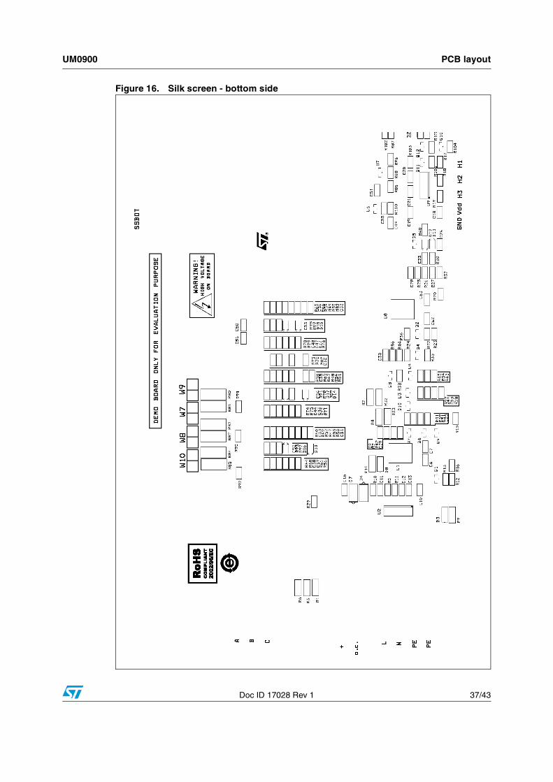
Figure 16. Silk screen - bottom side

Ordering information UM0900
38/43 Doc ID 17028 Rev 1
9 Ordering information
The demonstration board is available through the standard ordering system, the order code is: STEVAL-IHM025V1. The items delivered include the assembled application board, board documentation, PCB fabrication data such as gerber files, assembly files (pick and place) and component documentation.
10 Using the STEVAL-IHM025V1 with STM32 FOC firmware library
STM32 FOC firmware library v2.0 is a firmware library running on the STM3210B-MCKIT which allows the performing of the FOC of a PMSM in configuration with and without sensors.
This section describes the modifications to be applied to the STM32 FOC firmware library v2.0 in order to make the firmware compatible with the STEVAL-IHM025V1.
10.1 Environmental considerations
Warning: The STEVAL-IHM025V1 demonstration board must only be used in a power laboratory. The voltage used in the drive system presents a shock hazard.
The kit is not electrically isolated from the DC input. This topology is very common in motor drives. The microprocessor is grounded by the integrated ground of the DC bus. The microprocessor and associated circuitry are hot and MUST be isolated from user controls and communication interfaces.
Warning: All measuring equipment must be isolated from the main power supply before powering up the motor drive. To use an oscilloscope with the kit, it is safer to isolate the DC supply AND the oscilloscope. This prevents shock occurring as a result of touching any SINGLE point in the circuit, but does NOT prevent shock when touching two or more points in the circuit.
UM0900 Using the STEVAL-IHM025V1 with STM32 FOC firmware library
Doc ID 17028 Rev 1 39/43
An isolated AC power supply can be constructed using an isolation transformer and a variable transformer. A schematic of this AC power supply can be found in the “AN438, TRIAC + Microcontroller: safety precautions for development tools,” application note. (Although this Application Note was written for TRIAC, the isolation constraints still apply for switching semiconductor devices such as IGBT or MOSFET).
Note: Isolating the application rather than the oscilloscope is highly recommended in any case.
10.2 Hardware requirementsTo run the STEVAL-IHM025V1 together with the STM32 FOC firmware library, the following items are required:
● The board: STEVAL-IHM025V1
● High voltage insulated AC power supply up to 230 VAC
● J-link programmer (not included in the package)
● J-link insulating board (not included in the package)
● 3-phase brushless motor with permanent magnet rotor or a generic 3-phase induction motor (not included in the package)
● Insulated oscilloscope (as needed)
● Insulated multimeter (as needed).
10.3 Software requirementsTo customize, compile, and download the STM32 FOC firmware library v2.0 motor control firmware, the IAR tool “EWARM v5.30” must be installed. The free 32 kB limited version (referenced as “IAR KickStart Kit™” version) is available for download at:
http://supp.iar.com/Download/SW/?item=EWARM-KS32
10.4 Software modificationsApart from the parameters header file which can be edited by using the 'FOCGUI application' downloadable from:
http://www.st.com/mcu/modules.php?name=mcu&file=familiesdocs&fam=110&doc=59
the STM32 FOC firmware library v2.0 was designed in order to be compatible with the L6386 drivers. In order to make the firmware compatible with IPM STGIPL14K60, the polarity of the PWM driving the low-side transistors must be changed.
Using the STEVAL-IHM025V1 with STM32 FOC firmware library UM0900
40/43 Doc ID 17028 Rev 1
To achieve this task, perform the following steps:
1. In 'stm32f10x_svpwm_3shunt.c' substitute line 177 with:
TIM1_OCInitStructure.TIM_OCNPolarity = TIM_OCNPolarity_Low;
2. In 'stm32f10x_svpwm_1shunt.c' substitute line 311 with:
TIM1_OCInitStructure.TIM_OCNPolarity = TIM_OCNPolarity_Low;
3. In 'stm32f10x_svpwm_3shunt.c' substitute line 88 with:
#define LOW_SIDE_POLARITY TIM_OCIdleState_Set
4. In 'stm32f10x_svpwm_1shunt.c' substitute line 66 with:
#define LOW_SIDE_POLARITY TIM_OCIdleState_Set
5. In 'MC_MotorControl_Layer.c', substitute line 49 with:
#define NTC_THRESHOLD 25000
Note: This sets the overtemperature protection to about 85 °C.
UM0900 Conclusion
Doc ID 17028 Rev 1 41/43
11 Conclusion
This document describes the 1 kW 3-phase motor control STEVAL-IHM025V1 demonstration board based on IPM as a universal fully-evaluated platform.
12 References
1. STMicroelectronics STGIPL14K60 device datasheet - seewww.st.com/stonline/products/literature/ds/15589/stgipl14k60.pdf
2. STMicroelectronics VIPer16 device datasheet - seewww.st.com/stonline/products/literature/ds/15232.pdf
3. STMicroelectronics STGP10NC60KD device datasheet - seewww.st.com/stonline/products/literature/ds/11423/stgp10nc60kd.pdf
4. STMicroelectronics user manual UM0379: “STM3210B-MCKIT and STR750-MCKIT 3-phase motor control power stage” - seewww.st.com/stonline/products/literature/um/13031.pdf
5. STMicroelectronics user manual UM0580: “100W 3-phase inverter featuring L6390 and STD5NK52ZD for vector control STEVAL-IHM023V1” - seewww.st.com/stonline/products/literature/um/14958.pdf
6. STMicroelectronics user manual UM0723: “1kW 3-phase motor control demonstration board featuring L6390 drivers and STGP10NC60KD IGBT” - see www.st.com/stonline/products/literature/um/15870.pdf
Revision history UM0900
42/43 Doc ID 17028 Rev 1
13 Revision history
Table 8. Document revision history
Date Revision Changes
25-May-2010 1 Initial release.
UM0900
Doc ID 17028 Rev 1 43/43
Please Read Carefully:
Information in this document is provided solely in connection with ST products. STMicroelectronics NV and its subsidiaries (“ST”) reserve theright to make changes, corrections, modifications or improvements, to this document, and the products and services described herein at anytime, without notice.
All ST products are sold pursuant to ST’s terms and conditions of sale.
Purchasers are solely responsible for the choice, selection and use of the ST products and services described herein, and ST assumes noliability whatsoever relating to the choice, selection or use of the ST products and services described herein.
No license, express or implied, by estoppel or otherwise, to any intellectual property rights is granted under this document. If any part of thisdocument refers to any third party products or services it shall not be deemed a license grant by ST for the use of such third party productsor services, or any intellectual property contained therein or considered as a warranty covering the use in any manner whatsoever of suchthird party products or services or any intellectual property contained therein.
UNLESS OTHERWISE SET FORTH IN ST’S TERMS AND CONDITIONS OF SALE ST DISCLAIMS ANY EXPRESS OR IMPLIEDWARRANTY WITH RESPECT TO THE USE AND/OR SALE OF ST PRODUCTS INCLUDING WITHOUT LIMITATION IMPLIEDWARRANTIES OF MERCHANTABILITY, FITNESS FOR A PARTICULAR PURPOSE (AND THEIR EQUIVALENTS UNDER THE LAWSOF ANY JURISDICTION), OR INFRINGEMENT OF ANY PATENT, COPYRIGHT OR OTHER INTELLECTUAL PROPERTY RIGHT.
UNLESS EXPRESSLY APPROVED IN WRITING BY AN AUTHORIZED ST REPRESENTATIVE, ST PRODUCTS ARE NOTRECOMMENDED, AUTHORIZED OR WARRANTED FOR USE IN MILITARY, AIR CRAFT, SPACE, LIFE SAVING, OR LIFE SUSTAININGAPPLICATIONS, NOR IN PRODUCTS OR SYSTEMS WHERE FAILURE OR MALFUNCTION MAY RESULT IN PERSONAL INJURY,DEATH, OR SEVERE PROPERTY OR ENVIRONMENTAL DAMAGE. ST PRODUCTS WHICH ARE NOT SPECIFIED AS "AUTOMOTIVEGRADE" MAY ONLY BE USED IN AUTOMOTIVE APPLICATIONS AT USER’S OWN RISK.
Resale of ST products with provisions different from the statements and/or technical features set forth in this document shall immediately voidany warranty granted by ST for the ST product or service described herein and shall not create or extend in any manner whatsoever, anyliability of ST.
ST and the ST logo are trademarks or registered trademarks of ST in various countries.
Information in this document supersedes and replaces all information previously supplied.
The ST logo is a registered trademark of STMicroelectronics. All other names are the property of their respective owners.
© 2010 STMicroelectronics - All rights reserved
STMicroelectronics group of companies
Australia - Belgium - Brazil - Canada - China - Czech Republic - Finland - France - Germany - Hong Kong - India - Israel - Italy - Japan - Malaysia - Malta - Morocco - Philippines - Singapore - Spain - Sweden - Switzerland - United Kingdom - United States of America
www.st.com