Embed Size (px)
Citation preview

LAST UPDATED: 12/10/2019
Umbrella Tool Changer - Troubleshooting Guide
Umbrella Tool Changer - Troubleshooting Guide
Page 1 of 13 pages

Introduction
Umbrella Tool Changer - Troubleshooting Guide
Page 2 of 13 pages
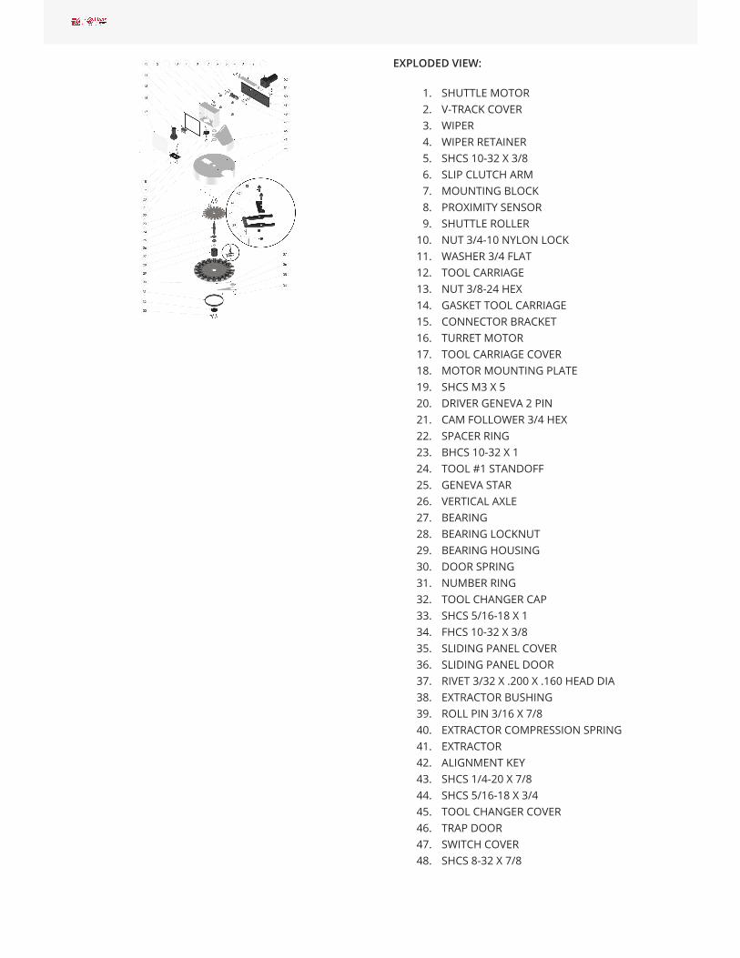
EXPLODED VIEW:
1. SHUTTLE MOTOR2. V-TRACK COVER3. WIPER4. WIPER RETAINER5. SHCS 10-32 X 3/86. SLIP CLUTCH ARM7. MOUNTING BLOCK8. PROXIMITY SENSOR9. SHUTTLE ROLLER
10. NUT 3/4-10 NYLON LOCK11. WASHER 3/4 FLAT12. TOOL CARRIAGE13. NUT 3/8-24 HEX14. GASKET TOOL CARRIAGE15. CONNECTOR BRACKET16. TURRET MOTOR17. TOOL CARRIAGE COVER18. MOTOR MOUNTING PLATE19. SHCS M3 X 520. DRIVER GENEVA 2 PIN21. CAM FOLLOWER 3/4 HEX22. SPACER RING23. BHCS 10-32 X 124. TOOL #1 STANDOFF25. GENEVA STAR26. VERTICAL AXLE27. BEARING28. BEARING LOCKNUT29. BEARING HOUSING30. DOOR SPRING31. NUMBER RING32. TOOL CHANGER CAP33. SHCS 5/16-18 X 134. FHCS 10-32 X 3/835. SLIDING PANEL COVER36. SLIDING PANEL DOOR37. RIVET 3/32 X .200 X .160 HEAD DIA38. EXTRACTOR BUSHING39. ROLL PIN 3/16 X 7/840. EXTRACTOR COMPRESSION SPRING41. EXTRACTOR42. ALIGNMENT KEY43. SHCS 1/4-20 X 7/844. SHCS 5/16-18 X 3/445. TOOL CHANGER COVER46. TRAP DOOR47. SWITCH COVER48. SHCS 8-32 X 7/8
Umbrella Tool Changer - Troubleshooting Guide
Page 3 of 13 pages
49. HOLDING PLATE50. LOCATING PIN51. DOOR OPENER BRACKET LOWER52. DOOR OPENER BRACKET UPPER
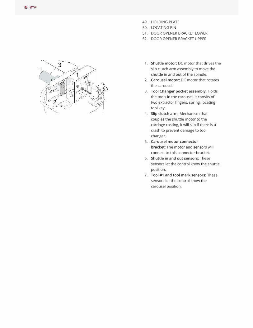
1. Shuttle motor: DC motor that drives theslip clutch arm assembly to move theshuttle in and out of the spindle.
2. Carousel motor: DC motor that rotatesthe carousel.
3. Tool Changer pocket assembly: Holdsthe tools in the carousel, it consits oftwo extractor fingers, spring, locatingtool key.
4. Slip clutch arm: Mechanism thatcouples the shuttle motor to thecarriage casting, it will slip if there is acrash to prevent damage to toolchanger.
5. Carousel motor connectorbracket: The motor and sensors willconnect to this connector bracket.
6. Shuttle in and out sensors: Thesesensors let the control know the shuttleposition.
7. Tool #1 and tool mark sensors: Thesesensors let the control know thecarousel position.
Umbrella Tool Changer - Troubleshooting Guide
Page 4 of 13 pages

Symptom Table
Umbrella Tool Changer - Troubleshooting Guide
Page 5 of 13 pages
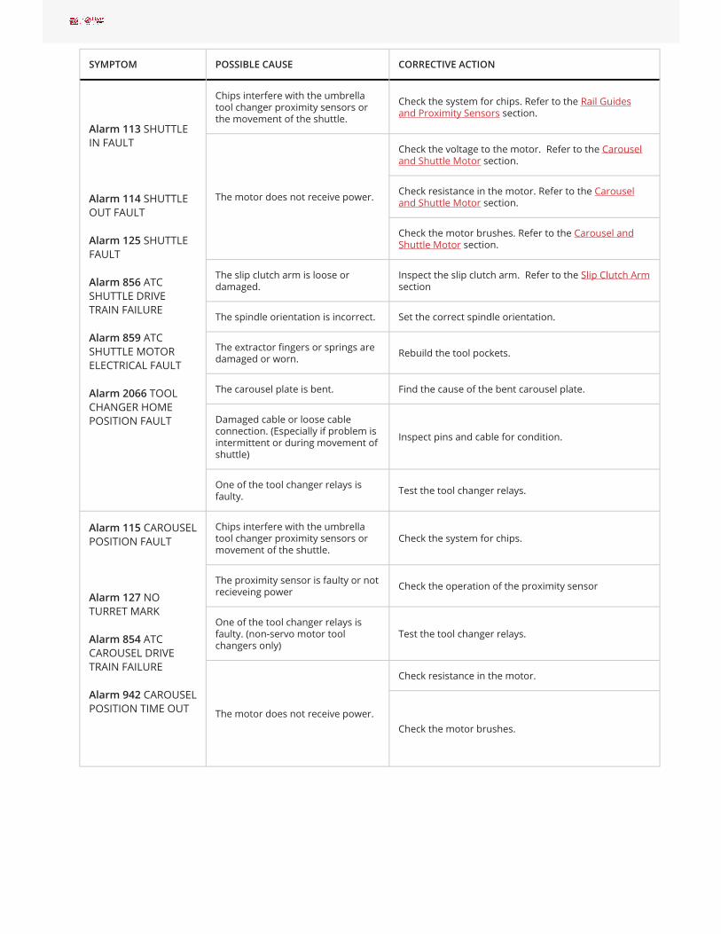
SYMPTOM POSSIBLE CAUSE CORRECTIVE ACTION
Chips interfere with the umbrellatool changer proximity sensors orthe movement of the shuttle.
Check the system for chips. Refer to the Rail Guidesand Proximity Sensors section.
Check the voltage to the motor. Refer to the Carouseland Shuttle Motor section.
Check resistance in the motor. Refer to the Carouseland Shuttle Motor section.The motor does not receive power.
Check the motor brushes. Refer to the Carousel andShuttle Motor section.
The slip clutch arm is loose ordamaged.
Inspect the slip clutch arm. Refer to the Slip Clutch Armsection
The spindle orientation is incorrect. Set the correct spindle orientation.
The extractor fingers or springs aredamaged or worn. Rebuild the tool pockets.
The carousel plate is bent. Find the cause of the bent carousel plate.
Damaged cable or loose cableconnection. (Especially if problem isintermittent or during movement ofshuttle)
Inspect pins and cable for condition.
Alarm 113 SHUTTLEIN FAULT
Alarm 114 SHUTTLEOUT FAULT
Alarm 125 SHUTTLEFAULT
Alarm 856 ATCSHUTTLE DRIVETRAIN FAILURE
Alarm 859 ATCSHUTTLE MOTORELECTRICAL FAULT
Alarm 2066 TOOLCHANGER HOMEPOSITION FAULT
One of the tool changer relays isfaulty. Test the tool changer relays.
Chips interfere with the umbrellatool changer proximity sensors ormovement of the shuttle.
Check the system for chips.
The proximity sensor is faulty or notrecieveing power Check the operation of the proximity sensor
One of the tool changer relays isfaulty. (non-servo motor toolchangers only)
Test the tool changer relays.
Check resistance in the motor.
Alarm 115 CAROUSELPOSITION FAULT
Alarm 127 NOTURRET MARK
Alarm 854 ATCCAROUSEL DRIVETRAIN FAILURE
Alarm 942 CAROUSELPOSITION TIME OUT The motor does not receive power.
Check the motor brushes.
Umbrella Tool Changer - Troubleshooting Guide
Page 6 of 13 pages

Alarm 115 CAROUSELPOSITION FAULT,during Power-up.
There is a software error (NGConly).
Set setting 81 TOOL AT POWER UP to 0, as a temporarywork around. Check NGC software release notes forwhen the error was corrected.
Note: Only a Certified Service Technician canupgrade the machine software.
The extractor fingers or springs aredamaged or worn. Rebuild the tool pockets.
The pull studs are incorrect.Tools fall or drop fromthe tool changer.
The tool is too heavy or too long.Check the tool specifications.
The lock nut on the shaft axle isloose.
The bolts at the bearing housing areloose.
The Umbrella ToolChanger Carousel Plateis Loose.
Mounting hardware in the toolchanger assembly is loose.
Check the lock nut on the shaft axle, bearing housingbolts and the 6 screws that hold the carousel plate.
The plastic riders on the carouseltrap door are damaged or missing.
The guide pin on the carousel trapdoor is damaged.
Inspect the carousel trap door.
The Tool changer is not aligned tothe spindle.
Use this procedure to align the Umbrella ToolChanger to the Spindle.
Procedure: Umbrella Tool Changer to SpindleAlignment
The Geneva driver or the Genevastar is damaged.
Examine the geneva driver and the geneva star fordamage. Use this procedure:Carousel Plate Replacement - Umbrella ToolChanger
Tool changes are noisy.
The shuttle roller bolts are notadjusted correctly.
Use this procedure to adjust or replace the shuttlerollers.
Procedure: Shuttle Roller Replacement andAdjustment
Umbrella Tool Changer - Troubleshooting Guide
Page 7 of 13 pages

The sliding panels do not fullyretract.
The sliding panels do not move smoothly. Thetools make scores or scratches on the innersurface of the carousel. Clean the slider and springassembly.
Use the correct procedure for slider and springremoval. Refer to Umbrella Tool Changer - Pocket -Replacement.
The trap door pivot point is notgreased. Grease the trap door pivot point.
There are chips between the trapdoor and the carousel.
The Umbrella ToolChanger Trap DoorDoes Not Open
The plastic trap door riders areworn.
Inspect the carousel trap door.
Rail Guides and Proximity Sensors
Corrective Action:
Check the top [1] and bottom [2] V-rails, and thewheels for chips. Check for damaged or wornwipers [3]. Some machines do not have a wiperbracket [4].
Remove any chips that prevent correct sensoroperation. Remove the carousel motor from thecarriage assembly. Remove the sensors [5] onboth sides of the carousel motor plate to cleanthem.
Remove the cam follower assembly [6] and lowerthe slip clutch arm [8] to move the carriageassembly and access the sensors [7] behind thecarriage assembly.
Older machine models use roller switches [5] inplace of the proximity sensors. The plunger androller must operate smoothly without sticking. Ifthe switches or sensors are clean, but do notoperate correctly, go to MECHANICAL LIMITSWITCH - TROUBLESHOOTINGGUIDE or PROXIMITY SENSOR -TROUBLESHOOTING GUIDE to troubleshootthem.
Umbrella Tool Changer - Troubleshooting Guide
Page 8 of 13 pages

Carousel and Shuttle Motor
Umbrella Tool Changer - Troubleshooting Guide
Page 9 of 13 pages
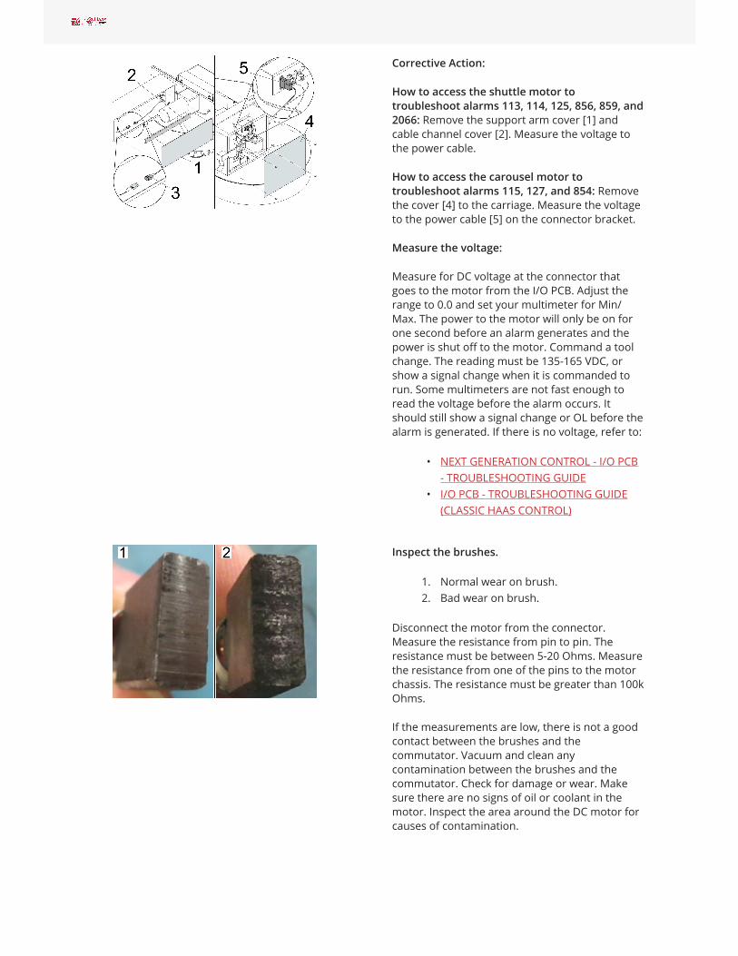
Corrective Action:
How to access the shuttle motor totroubleshoot alarms 113, 114, 125, 856, 859, and2066: Remove the support arm cover [1] andcable channel cover [2]. Measure the voltage tothe power cable.
How to access the carousel motor totroubleshoot alarms 115, 127, and 854: Removethe cover [4] to the carriage. Measure the voltageto the power cable [5] on the connector bracket.
Measure the voltage:
Measure for DC voltage at the connector thatgoes to the motor from the I/O PCB. Adjust therange to 0.0 and set your multimeter for Min/Max. The power to the motor will only be on forone second before an alarm generates and thepower is shut off to the motor. Command a toolchange. The reading must be 135-165 VDC, orshow a signal change when it is commanded torun. Some multimeters are not fast enough toread the voltage before the alarm occurs. Itshould still show a signal change or OL before thealarm is generated. If there is no voltage, refer to:
• NEXT GENERATION CONTROL - I/O PCB- TROUBLESHOOTING GUIDE
• I/O PCB - TROUBLESHOOTING GUIDE(CLASSIC HAAS CONTROL)
Inspect the brushes.
1. Normal wear on brush.2. Bad wear on brush.
Disconnect the motor from the connector.Measure the resistance from pin to pin. Theresistance must be between 5-20 Ohms. Measurethe resistance from one of the pins to the motorchassis. The resistance must be greater than 100kOhms.
If the measurements are low, there is not a goodcontact between the brushes and thecommutator. Vacuum and clean anycontamination between the brushes and thecommutator. Check for damage or wear. Makesure there are no signs of oil or coolant in themotor. Inspect the area around the DC motor forcauses of contamination.
Umbrella Tool Changer - Troubleshooting Guide
Page 10 of 13 pages

Slip Clutch Arm
Spindle Orientation
Tool Changer Relays
Corrective Action:
Inspect the slip clutch arm: Remove and inspectthe cam follower assembly [1] for damage andchips. Push the carousel motor housing in thedirection of the spindle to get access to the slipclutch arm [2]. Manually turn the slip clutch arm[2] through 180° of movement. It should rotatesmoothly, but with heavy resistance. If the armdoes not move smoothly, the shuttle motor [3] isfaulty.
Corrective Action:
Find the cause of the spindle orientation error.
Make sure spindle drive and encoder belts havethe correct tension. Make sure the spindle motorpulley and encoder pulley are not worn.
Refer to these procedures
• CHC - UMBRELLA TOOL CHANGER - SETPARAMETER 257 - SPINDLEORIENTATION OFFSET
• NGC - UMBRELLA TOOL CHANGER -SPINDLE ORIENTATION OFFSET
Corrective Action:
Test the suspected relay: Exchange the relaywith another relay. If the alarm changes to adifferent alarm, the relay is at fault.
For example: If the machine displays Alarm 113,change the K9 relay with the K10 relay. If thealarm changes to Alarm 114, the relay is faulty. Ifthe alarm does not chage, proceed to othertroubleshooting sections.
Umbrella Tool Changer - Troubleshooting Guide
Page 11 of 13 pages

Tool Pocket
Carousel Plate and Tool Release Piston Adjustment
Carousel Trap Door
Corrective Action:
The extractor fingers and spring hold the tool inthe tool pocket. Worn or damaged fingers orsprings can let the tool fall.
Refer to:
• VMC - UMBRELLA TOOL CHANGER -POCKET - REPLACEMENT
• VIDEO - UMBRELLA/CAROUSEL TOOLCHANGER MAINTENANCE
Corrective Action:
If the tool-release piston (TRP) sensors are notadjusted correctly, a tool can get stuck in thespindle taper, or the drawbar might not release atool. Damage to the umbrella tool changer canoccur. Adjust the tool release piston switchescorrectly. Refer to the TRP - PROXIMITY SENSOR -ADJUSTMENT procedure.
Go to UMBRELLA - TOOL CHANGER – CAROUSELPLATE - REPLACEMENT for carousel platereplacement instructions.
Corrective Action:
Check for damage to the guide pin [1], trap door[2], and the plastic riders [3].
Refer to the UMBRELLA TOOL CHANGER - GUIDEPIN AND TRAP DOOR - REPLACEMENT procedure.
Umbrella Tool Changer - Troubleshooting Guide
Page 12 of 13 pages

Electrical Diagram
Umbrella Tool Changer - Troubleshooting Guide
Page 13 of 13 pages


![Stylus System Changer Set-up Procedures for Zeiss …...[Type text] [Type text] [Type text] Tool Changer Page 1 of 23 Stylus System Changer Set-up Procedures for Zeiss CMMs Table of](https://img.pdfslide.net/doc/110x75/5e6d26f83912ef023b4ec125/stylus-system-changer-set-up-procedures-for-zeiss-type-text-type-text-type.jpg)


![Stylus System Changer Set-up Procedures for Zeiss CMMs · · 2014-10-29Type text] [Type text] [Type text] Tool Changer Page 5 of 12 4. Open the Automatic Stylus System Changer and](https://img.pdfslide.net/doc/110x75/5b0163557f8b9ad85d8e0e2b/stylus-system-changer-set-up-procedures-for-zeiss-cmms-text-type-text-type-text.jpg)