Embed Size (px)
Citation preview

UML Collaboration Diagram

Recap
• System Sequence Diagrams (SSD)• UML for SSD• Examples

Contents
• Collaboration Diagrams• UML notation• Examples

Collaboration Diagrams • Show a particular sequence of messages exchanged
between a number of objects– this is what sequence diagrams do too!
• Use sequence diagrams to model flows of control by time ordering– Better for demonstrating the ordering of the messages– Not suitable for complex iteration and branching
• Use collaboration diagrams to model flows of control by organization– Good at showing the static connections among the
objects while demonstrating a particular sequence of messages at the same time

Collaboration Diagrams• Shows the relationship between objects and the
order of messages passed between them between them.
• The objects are listed as rectangles and arrows indicate the messages being passed.
• The numbers next to the messages are called sequence numbers. They show the sequence of the messages as they are passed between the objects convey the same information as sequence diagrams, but focus on object roles instead of the time sequence.
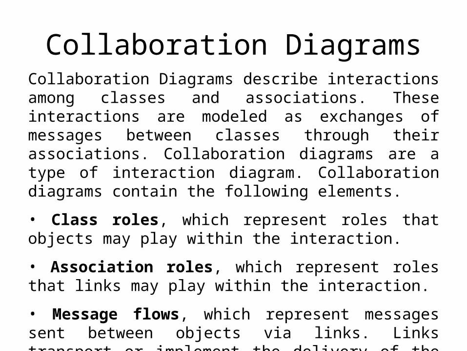
Collaboration Diagrams describe interactions among classes and associations. These interactions are modeled as exchanges of messages between classes through their associations. Collaboration diagrams are a type of interaction diagram. Collaboration diagrams contain the following elements.
• Class roles, which represent roles that objects may play within the interaction.
• Association roles, which represent roles that links may play within the interaction.
• Message flows, which represent messages sent between objects via links. Links transport or implement the delivery of the message.
Collaboration Diagrams

UML Collaboration diagrams (interaction diagrams) illustrate the relationship and interaction between software objects. They require use cases, system operation contracts, and domain model to already exist. The collaboration diagram illustrates messages being sent between classes and objects (instances). A diagram is created for each system operation that relates to the current development cycle (iteration).
Collaboration Diagrams

Collaboration Diagrams
User
Catalog
Reservations
start
1: look up2: title data
3 : [not available] reserve title
4 : title returned
5 : hold title
6 : borrow title
6: remove reservation
5: title available

Collaboration Diagram
:ProductOrder :StockItem
:Order
:OrderEntryWindow
:ReorderItem
:DeliveryItem
1:prepare()
1.1:*prepare()
1.1.1:check() 1.1.2:[check==true]remove()
1.1.2.1:needsToReorder()
1.1.2.2:new
1.1.3:[check==true]new
message
object
link sequence number
Sequence numbers are usedto show the time ordering amongthe messages

Collaboration Diagrams
• Class diagrams indicates what classes are part of our system, what they offer, how they relate, but they don’t tell us how they communicate.
• Collaboration diagrams show (used to model) how objects interact and their roles.
• They are very similar to sequence diagrams. Actually they are considered as a cross between class and sequence diagram.
• Sequence Diagrams are arranged according to Time.• Collaboration Diagrams represent the structural
organization of object.• [Both sequence and collaboration diagrams are called
interaction diagrams]
10

Collaboration Diagram – URS Add Subject Scenario
11
u:URSDatabase
<<self>>
a:AddSubCmd
2:[if cmdN = ADDSUB]AddSubCmd(u,cmdA)
<<local>>
{new}
{transient}
3: execute()
3.2: addSubject(sub1)
1:parseCommand(cmd)
procCmd(cmd)
sub1:Subject
3.1: Subject(id,name){new}

Collaboration Diagram – URS Add Subject Scenario
12
u:URSDatabase
<<self>>1:parseCommand(cmd)
procCommand(cmd)
class URSDatabase{ private String cmdN; private String cmdA; private parseCommand(String cmd){ cmdN = …. cmdA = …. } public procCommand(String cmd){ parseCommand(cmd); }}
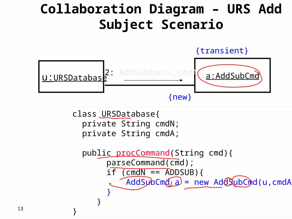
Collaboration Diagram – URS Add Subject Scenario
13
u:URSDatabase a:AddSubCmd 2: AddSubCmd(u,cmdA)
{new}
{transient}
class URSDatabase{ private String cmdN; private String cmdA;
public procCommand(String cmd){ parseCommand(cmd); if (cmdN == ADDSUB){ AddSubCmd a = new AddSubCmd(u,cmdA); } }}

Collaboration Diagrams
• Collaborations Diagrams show transient links that exists between objects.– <<self>> - A message from object to itself– << local>> - A message sent due to the object
begin defined as a local variable in the method.– <<parameter>> - The object reference was sent
as a parameter to the method.– <<global>> The object is global.
14

Collaboration Diagrams
• UML Collaboration Diagrams– Collaboration Diagram Semantics– Collaboration Diagram Notation– Collaboration Diagram Examples– Collaboration Diagram Issues
Collaboration Diagram Semantics
• Member of the Behavioral Group of diagrams as well as Sequence, State chart, and Activity diagrams
• Behavioral description includes• Static - structural description on the participants• Dynamic - description on the execution of the
actions• Collaboration – set of participants and interactions
which are meaningful in a context

Collaboration Diagram Semantics
• Purpose – models the exchange of messages between objects to achieve something
• Can be attached to: operation or use case class
• Parameterized collaboration – can be reused can assist in defining the structural aspects of a design pattern

Collaboration Diagram Notation
• Represents a Collaboration and Interaction• Collaboration - set of objects and their interactions in a
specific context• Interaction - set of messages exchanged in a collaboration to
produce a desired result• Objects – rectangles containing the object signature – object
signature: object name : object Class • object name (optional) - starts
with lowercase letter class name (mandatory) - starts with uppercase letter – objects connected by lines – user (stick man) can appear

Messages
• Messages – are labeled like C and Java function calls followed by round brackets, and can have parameters and return values are followed by an arrow to show direction internal messages are numbered, starting from 1

Collaboration Diagram Example

Collaboration Diagram Issues Message Signature• Guard • condition applied to the message
• in square brackets at the start of the signature• Sequence number
• numbers separated by dots, ending in a colon• Return value
• name followed by :=

Collaboration Diagram Issues
• Operation name• Argument list
• names separated by commas, within round brackets• Types of message flows
• Synchronous, asynchronous, simple• Multiplicity of objects
• How can messages sent to a multiplicity (e.g., an array) of objects be represented?

Types of Messages• Simple• Indicates flow of control - sender waits until receiver processes message• Default• Shown by an 'empty' arrow• Synchronous• Indicates nested flow of control used to ensure that state cannot be
compromised by external factors• e.g., not interrupted by the operating system• shown by a 'filled' arrow • Asynchronous• A signal from one object to another• Shown as half an empty arrow

Multiplicity in Collaboration Diagrams
• A server object needs to send a message to each user logged in, and another message to the audit object (which keeps a track of messages sent)

Collaboration Diagram Example

UML Collaboration Diagrams: The Dynamic View (Digital Sound Recorder)

Collaboration Diagrams

Example

Example

SSD Vs Collaboration diagrams

Summary• Collaboration Diagram Semantics
– objects and messages– static representation of messages which could be sent– sequence of messages indicated
• Collaboration Diagram Notation– rectangles for objects
• Object signature: name : Class– messages with arrows
• Message signature– [ guard] sequence number : result := messageName(int)
• Collaboration Diagram Issues– multiplicity– when to use


![SGX-SSD: A Policy-based Versioning SSD with Intel SGX · Existing Solution: Versioning SSD[BVSSD, Systor12], [Project Almanac, Eurosys19] §Versioning SSD implements versioning system](https://img.pdfslide.net/doc/110x75/60ae19522c0a8f54c27ad581/sgx-ssd-a-policy-based-versioning-ssd-with-intel-sgx-existing-solution-versioning.jpg)