Embed Size (px)
Citation preview
UML for Embedded Systems Development--Revisited

table_05_00
**
*
**
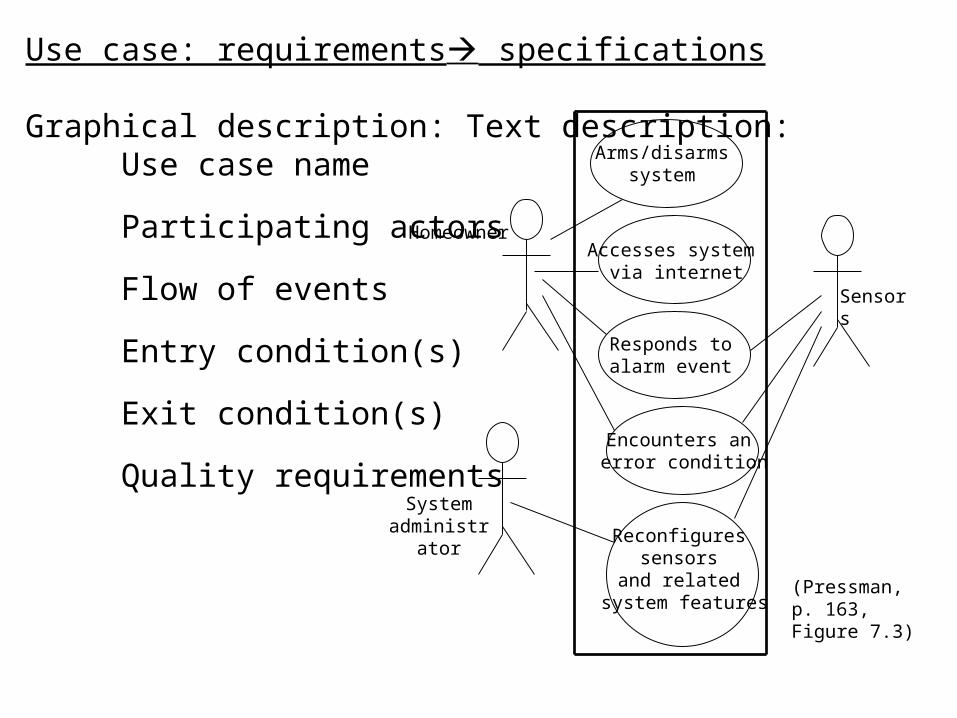
Arms/disarms system
Accesses system via internet
Responds to alarm event
Encounters an error condition
Reconfigures sensors
and related system features
Homeowner
System administrator
Sensors
(Pressman, p. 163, Figure 7.3)
Use case: requirements specifications Graphical description:
Text description: Use case name
Participating actors
Flow of events
Entry condition(s)
Exit condition(s)
Quality requirements
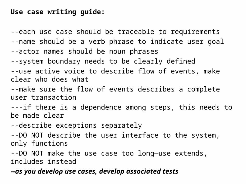
Use case writing guide:
--each use case should be traceable to requirements
--name should be a verb phrase to indicate user goal
--actor names should be noun phrases
--system boundary needs to be clearly defined
--use active voice to describe flow of events, make clear who does what
--make sure the flow of events describes a complete user transaction
---if there is a dependence among steps, this needs to be made clear
--describe exceptions separately
--DO NOT describe the user interface to the system, only functions
--DO NOT make the use case too long—use extends, includes instead
--as you develop use cases, develop associated tests
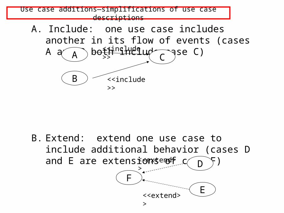
Use case additions—simplifications of use case descriptions
A. Include: one use case includes another in its flow of events (cases A and B both include case C)
B. Extend: extend one use case to include additional behavior (cases D and E are extensions of case F)
A
B
C<<include>>
<<include>>
FE
D
<<extend>>
<<extend>>

Use case additions (continued)
C. Inheritance: one use case specializes the more general behavior of another G and H specialize behavior of J)
H
J
authenticate
Authenticate with card
Authenticate with password
G
Class and object diagrams:Identify Objects from Use Case Specifications:USE ENDUSER’s TERMS AS MUCH AS POSSIBLE
Entity objects: “things”, for example:--nouns (customer, hospital, infection)--real-world entities (resource, dispatcher)--real-world activities to be tracked (evacuation_plan)--data sources or sinks (printer)
Boundary objects: system interfaces, for example:--controls (report(emergencybutton)--forms (savings_deposit_form)--messages (notify_of_error)
Control objects: usually one per use case--coordinate boundary and entity objects in the use case
Use the identified objects in a sequence diagram to carry out the use case

fig_05_01
Example: graphical use case
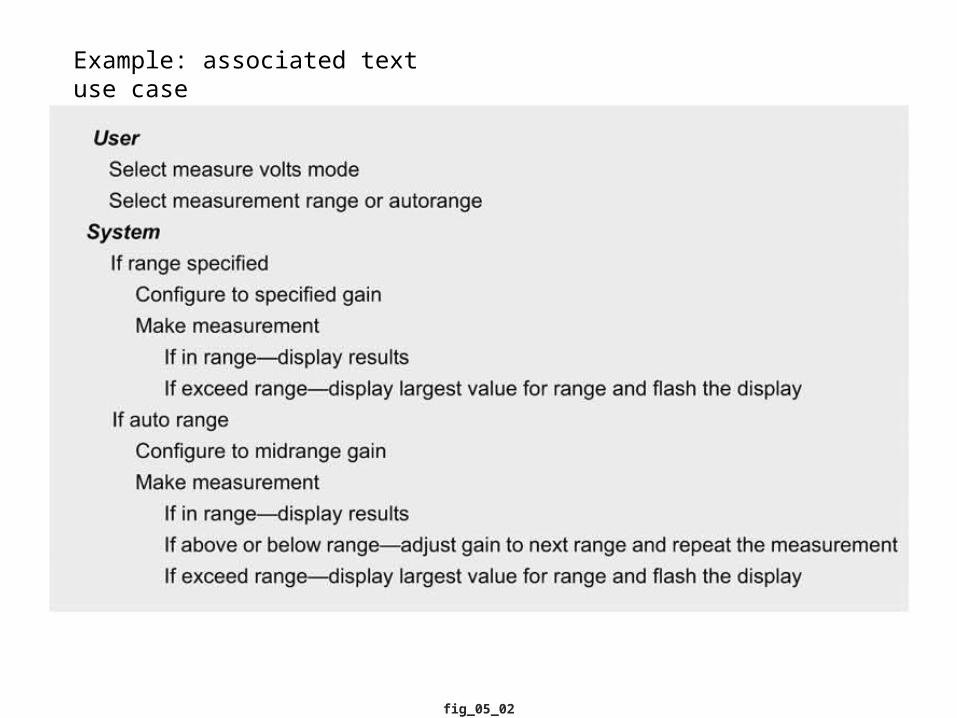
fig_05_02
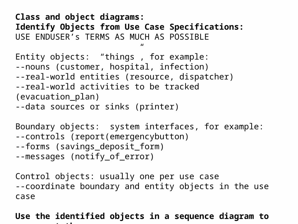
Example: associated text use case

fig_05_03
Things in the system: classes / objects

fig_05_04
Example: classes

fig_05_05
Example: classes—interface relation
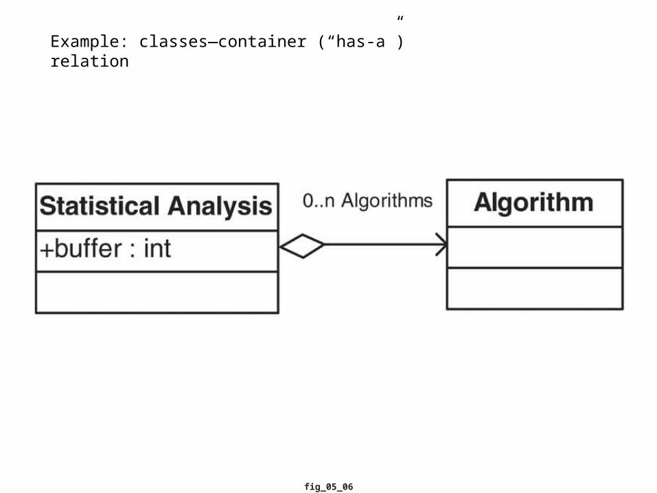
fig_05_06
Example: classes—container (“has-a”) relation
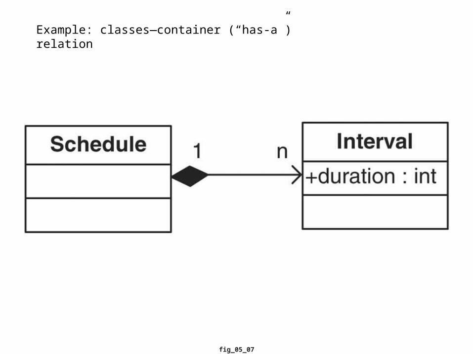
fig_05_07
Example: classes—container (“has-a”) relation
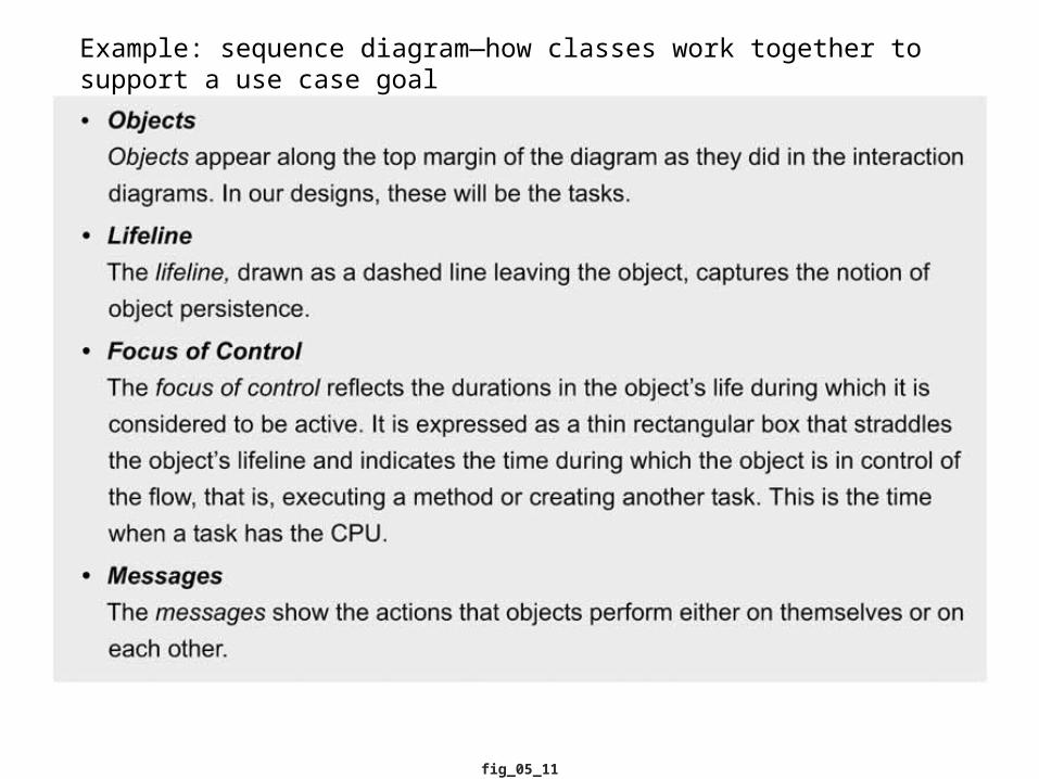
fig_05_11
Example: sequence diagram—how classes work together to support a use case goal
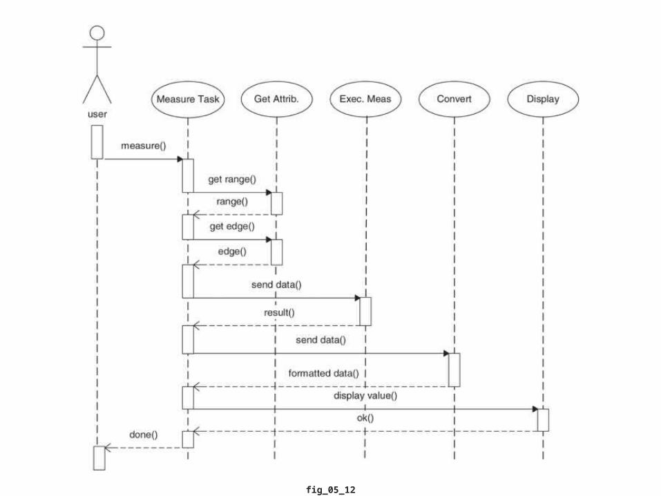
fig_05_12
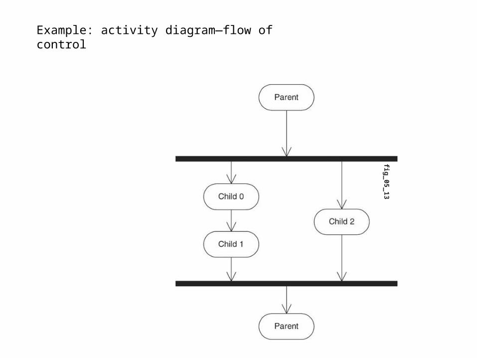
fig_05_13
Example: activity diagram—flow of control

fig_05_14
fig_05_15

fig_05_16
State diagrams--options

fig_05_18
Example: state diagrams
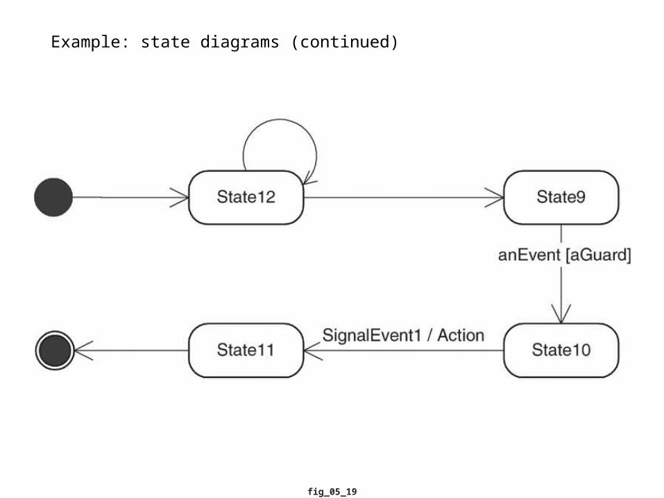
fig_05_19
Example: state diagrams (continued)

Note: UML was developed for modeling software. For modeling embedded systems, there are additional behaviors that must be addressed.
G. Martin, CADENCE, DATE 2002:
--Embedded systems are composed of multiple subsystems or functional units
--These components carry out computation and communication tasks using a heterogeneous set of models of computation
--Components may be implemented in a variety of ways, combining hardware and software
--Mapping of function to architecture is not fixed; “design space exploration” is important for optimization
--High-level system modeling and delay of commitment to particular components until late in the design cycle is desirable
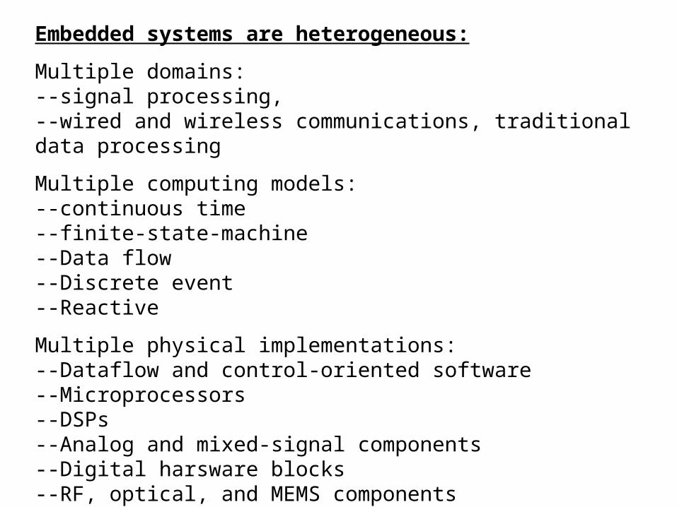
Embedded systems are heterogeneous:
Multiple domains: --signal processing, --wired and wireless communications, traditional data processing
Multiple computing models: --continuous time --finite-state-machine--Data flow--Discrete event--Reactive
Multiple physical implementations:--Dataflow and control-oriented software--Microprocessors--DSPs--Analog and mixed-signal components--Digital harsware blocks--RF, optical, and MEMS components
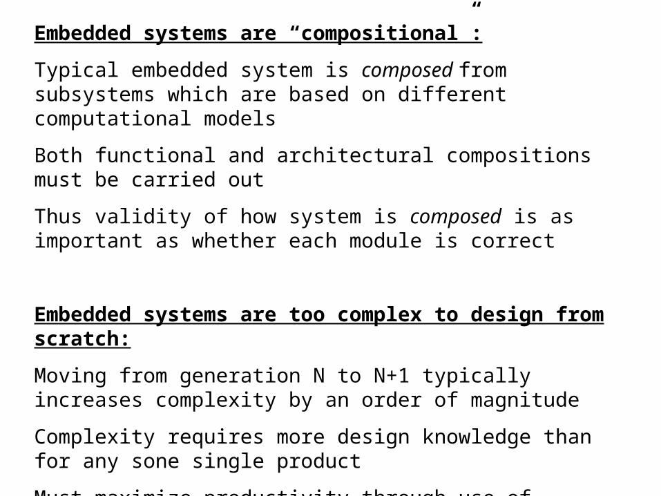
Embedded systems are “compositional”:
Typical embedded system is composed from subsystems which are based on different computational models
Both functional and architectural compositions must be carried out
Thus validity of how system is composed is as important as whether each module is correct
Embedded systems are too complex to design from scratch:
Moving from generation N to N+1 typically increases complexity by an order of magnitude
Complexity requires more design knowledge than for any sone single product
Must maximize productivity through use of embedded system platforms, reuse, synthesis based on system-level models
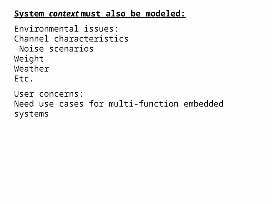
System context must also be modeled:
Environmental issues:Channel characteristics Noise scenariosWeightWeatherEtc.
User concerns:Need use cases for multi-function embedded systems

Necessary additions:
“Platform” model
Tools to move from one platform level to another
Constraint definition and budgeting methodology to control optimization process in design transformation and synthesis

“UML-platform”—components to be added:
--“uses” and “needs” relationships to allow platform components to request and receive services from other components
--”stack” stereotype to describe hierarchical layered implementations of platform services
--”peer” stereotype for components and services at same level
--Quality of Service (QoS) tags which can be derived from specifications, mapped into constraints, and used to guide implementation choices [including time deadlines]
--defined platform layers for classifying services for deployment:--ASP—application specific programmable--API—application programming interface--ARC—architectural
--inclusion of “extension points” for future application requirements and new or variant service offerings