Embed Size (px)
Citation preview
P
Iitc
tA9
A“LAaGc
Int. J. Radiation Oncology Biol. Phys., Vol. 68, No. 1, pp. 301–310, 2007Copyright © 2007 Elsevier Inc.
Printed in the USA. All rights reserved0360-3016/07/$–see front matter
doi:10.1016/j.ijrobp.2006.11.056
HYSICS CONTRIBUTION
UNCERTAINTY ESTIMATION IN INTENSITY-MODULATED RADIOTHERAPYABSOLUTE DOSIMETRY VERIFICATION
FRANCISCO SÁNCHEZ-DOBLADO, PH.D.,*† GÜNTHER H. HARTMANN, PH.D.,‡ JAVIER PENA, M.SC.,§
ROBERTO CAPOTE, PH.D.,¶ MARTA PAIUSCO M.SC.,� BERNHARD RHEIN, PH.D.,‡
ANTONIO LEAL, PH.D.,*†AND JUAN IGNACIO LAGARES, M.SC.,*†
*Radiofísica. Hospital Universitario Virgen Macarena, Sevilla, Spain; †Departamento de Fisiología Médica y Biofísica, Facultad deMedicina, Universidad de Sevilla, Sevilla, Spain; ‡Abt Medizinische Physik in der Strahlentherapie, Deutsches
Krebsforschungszentrum, Heidelberg, Germany; §Departamento de Física de Partículas, Facultade de física, Universidade deSantiago de Compostela, Santiago de Compostela, Spain; ¶Nuclear Data Section, International Atomic Energy Agency, Vienna,
Austria; �Fisica Sanitaria, Arcispedale S. Maria Nuova, Reggio Emilia, Italy
Purpose: Intensity-modulated radiotherapy (IMRT) represents an important method for improving RT. TheIMRT relative dosimetry checks are well established; however, open questions remain in reference dosimetrywith ionization chambers (ICs). The main problem is the departure of the measurement conditions from thereference ones; thus, additional uncertainty is introduced into the dose determination. The goal of this study wasto assess this effect systematically.Methods and Materials: Monte Carlo calculations and dosimetric measurements with five different detectorswere performed for a number of representative IMRT cases, covering both step-and-shoot and dynamic delivery.Results: Using ICs with volumes of about 0.125 cm3 or less, good agreement was observed among the detectorsin most of the situations studied. These results also agreed well with the Monte Carlo-calculated nonreferencecorrection factors (c factors). Additionally, we found a general correlation between the IC position relative to asegment and the derived correction factor c, which can be used to estimate the expected overall uncertainty ofthe treatment.Conclusion: The increase of the reference dose relative standard uncertainty measured with ICs introduced bynonreference conditions when verifying an entire IMRT plan is about 1–1.5%, provided that appropriatesmall-volume chambers are used. The overall standard uncertainty of the measured IMRT dose amounts toabout 2.3%, including the 0.5% of reproducibility and 1.5% of uncertainty associated with the beam calibrationfactor. Solid state detectors and large-volume chambers are not well suited to IMRT verification dosimetrybecause of the greater uncertainties. An action level of 5% is appropriate for IMRT verification. Greaterdiscrepancies should lead to a review of the dosimetric procedure, including visual inspection of treatmentsegments and energy fluence. © 2007 Elsevier Inc.
Intensity-modulated radiotherapy, Radiotherapy quality assurance, Uncertainty estimation, Small-field dosim-
etry, Reference dosimetry.ncdpio
qacRDaatv
A
INTRODUCTION
ntensity-modulated radiotherapy (IMRT) has become anmportant technique for delivering a highly conformed doseo an irregularly shaped target volume. Because of the largeromplexity compared with classic conformal therapy tech-
Reprint requests to: Francisco Sánchez-Doblado, Ph.D., Depar-amento de Fisiología Médica y Biofísica, Facultad de Medicina,vda, Sánchez Pizjuan, 4, Sevilla E41009, Spain. Tel: (�34)81-56-3100; Fax: (�34) 981-52-1091; E-mail: [email protected]
Conflict of interest: none.cknowledgments—The authors are indebted to the SpanishFondo de Investigaciones Sanitarias” (FIS) and the Universityaw (LOU) contract between the University of Seville and thendalusian Health Service (SAS) for financial support. We would
lso like to thank the European Commission, the Directorateeneral of Health and Consumer Protection–Europe Against Can-
er Program, and the ESQUIRE II project (education, science, and
301
iques, IMRT requires an enhanced quality assurance pro-edure. This applies in particular to the step of deliveredose verification. Because of time constraints, treatmentlanning systems (TPSs) normally deal only in an approx-mate manner with the physical processes of the interactionf ionizing radiation in the treatment head and dose depo-
uality assurance for radiotherapy) for support through grantgreement SPC.2002480. Special thanks to Angelika Höss for TPSalculations and data management. J. Pena acknowledges theamón Areces Foundation for its financial support. F. Sánchez-oblado is indebted to the DKFZ for the research agreement that
llowed the treatment selection and measurements to be performedt its facilities. Finally, the authors want to express their gratitudeo the Centro de Supercomputación de Galicia (CESGA) for pro-iding the computer resources for IC simulation.Received April 7, 2006, and in revised form Sept 25, 2006.
ccepted for publication Nov 30, 2006.
stnto
dIecdcIa6(cct
s(dfccIsbu“
C
prb
TtdfStv
ttatfFMil
gTbomccd
C
ft
F
1
111
Ia
302 I. J. Radiation Oncology ● Biology ● Physics Volume 68, Number 1, 2007
ition inside the patient. Therefore, critical results such ashe determination of the absorbed dose per monitor uniteed experimental verification (1–6). Discrepancies be-ween the calculated and measured absorbed dose in regionsf high-density gradients have been reported (7–11).
The experimental measurement of the reference absorbedose to water at a point of interest has special problems inMRT because of the inherent lack of charged particlequilibrium in some of the beamlets and thus the nonappli-ability of the Spencer-Attix cavity theory (12) during theirelivery. The source of this deviation from the referenceonditions stands in the narrow beams used to build anMRT plan (13). Although it has been confirmed that water/ir stopping power ratios do not change substantially in-MV IMRT beamlets compared with the reference fields14), additional correction factors should be introduced toonsider the perturbation introduced by the ionizationhambers (ICs). As a consequence, increased uncertainty inhe dose determination can be expected.
Early attempts to calculate the correction factors formall-field IC dosimetry were presented by Paskalev et al.15, 16). Verhaegen (17) stressed the importance of using aetailed description of the detector for high-accuracy inter-ace dosimetry. Several investigators have evaluated ICorrection factors for reference dosimetry in nonequilibriumonditions (18–22). A very detailed model of the employedC had been used in the Monte Carlo (MC) calculations byome investigators (17–22). All these correction factors cane considered as estimators of the experimental verificationncertainty, because they quantify the deviations from thetrue” delivered dose.
In particular, a new correction factor c was introduced by
Table 1. Plans selected for intensity-modulated radiotherapyverification
Case No. Technique
DKFZ Heidelberg (step-and-shoot IMRT)1 Head and neck: hypopharynx carcinoma2 Head and neck: osteosarkoma3 Prostate carcinoma4 Sacral chordoma5 Head and neck: menengeoma6 Head and neck: menengeoma7 Head and neck: nasopharynx carcinoma
ASMNH Reggio Emilia (dynamic MLC IMRT)8 Prostate carcinoma9 Head and neck: thyroid carcinoma0 Head and neck: neck metastases from unknown
primary1 Head and neck: hypopharynx carcinoma2 Prostate carcinoma3 Head and neck: hypopharynx carcinoma
Abbreviations: DKFZ � Deutsches Krebsforschungszentrum;MRT � intensity-modulated radiotherapy; ASMNH � Arcisped-le Santa Maria Nuova; MLC � multileaf collimator.
apote et al. (18) that was very useful to characterize a s
otential change in the perturbation factors between theeference conditions and the IMRT beamlet situation. It cane expressed as:
c �fw,a
non�reference
fw,areference
�
�Dw,Q,nonreference
Da,Q,nonreference�
�Dw,Q,reference
Da,Q,reference� . (1)
he factor c is equal to 1 (by definition) for a reference beam;herefore, it describes how big the difference is between theosimetry for nonreference and reference conditions (18). Thisactor is equal to a factor CQ
IMRT, introduced by Bouchard andeuntjens (19), to correct the absorbed dose-to-water calibra-
ion coefficient ND,wQ for fluence perturbation effects in indi-
idual segments of an IMRT delivery.The scope of the present work was to estimate the uncer-
ainty of the reference dosimetry in IMRT verificationhrough the evaluation of the scatter of the reference doseround its mean value as determined using different radia-ion detectors and also through the comparison of the cactors for each IC as determined by the MC simulations.or this purpose, systematic dosimetric measurements andC simulations were performed to determine the dose
nside a water-equivalent phantom delivered by several se-ected IMRT plans, both step-and-shoot and dynamic.
We were especially interested in the ICs because they areiven preference in determining the absolute absorbed dose.he concept of determining the absorbed dose using cali-rated ICs is well established (e.g., by the international codef practice TRS 398 [24]). It has been frequently recom-ended to use other types of detectors only after having
hecked their response relative to the IC. Therefore, ICs areonsidered, by far, the more common and trusted radiationetectors in RT facilities.
METHODS AND MATERIALS
ase selectionTo study representative IMRT plans, 13 cases were selected
rom clinical case databases of the Deutsches Krebsforschungszen-rum (DKFZ, Heidelberg, Germany) and the Arcispedale Santa
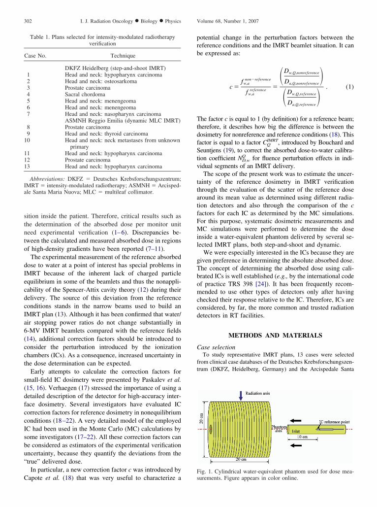
ig. 1. Cylindrical water-equivalent phantom used for dose mea-
urements. Figure appears in color online.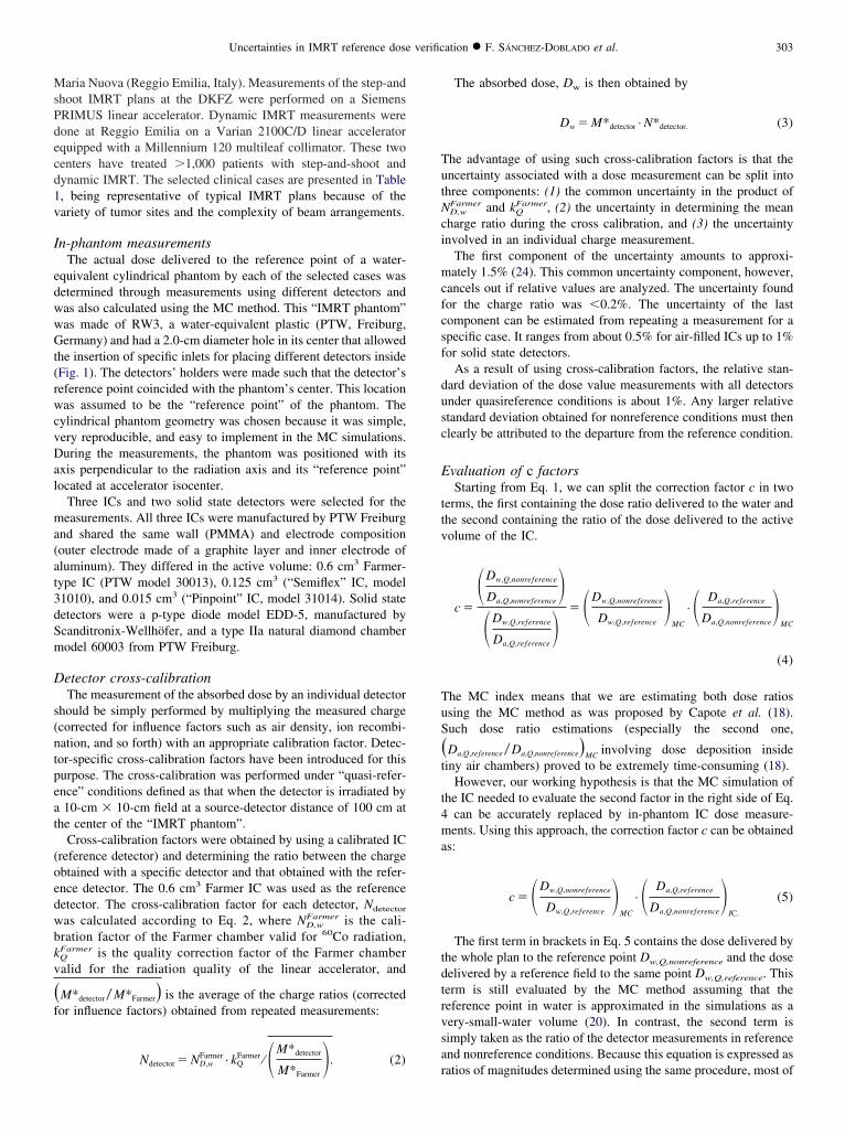
MsPdecd1v
I
edwwGt(rwcvDal
ma(at3dSm
D
s(ntpeat
(oedwbkv
�f
TutNci
mcfcsf
dusc
E
ttv
TuS
�t
t4ma
tdtrvsa
303Uncertainties in IMRT reference dose verification ● F. SÁNCHEZ-DOBLADO et al.
aria Nuova (Reggio Emilia, Italy). Measurements of the step-andhoot IMRT plans at the DKFZ were performed on a SiemensRIMUS linear accelerator. Dynamic IMRT measurements wereone at Reggio Emilia on a Varian 2100C/D linear acceleratorquipped with a Millennium 120 multileaf collimator. These twoenters have treated �1,000 patients with step-and-shoot andynamic IMRT. The selected clinical cases are presented in Table, being representative of typical IMRT plans because of theariety of tumor sites and the complexity of beam arrangements.
n-phantom measurementsThe actual dose delivered to the reference point of a water-
quivalent cylindrical phantom by each of the selected cases wasetermined through measurements using different detectors andas also calculated using the MC method. This “IMRT phantom”as made of RW3, a water-equivalent plastic (PTW, Freiburg,ermany) and had a 2.0-cm diameter hole in its center that allowed
he insertion of specific inlets for placing different detectors insideFig. 1). The detectors’ holders were made such that the detector’seference point coincided with the phantom’s center. This locationas assumed to be the “reference point” of the phantom. The
ylindrical phantom geometry was chosen because it was simple,ery reproducible, and easy to implement in the MC simulations.uring the measurements, the phantom was positioned with its
xis perpendicular to the radiation axis and its “reference point”ocated at accelerator isocenter.
Three ICs and two solid state detectors were selected for theeasurements. All three ICs were manufactured by PTW Freiburg
nd shared the same wall (PMMA) and electrode compositionouter electrode made of a graphite layer and inner electrode ofluminum). They differed in the active volume: 0.6 cm3 Farmer-ype IC (PTW model 30013), 0.125 cm3 (“Semiflex” IC, model1010), and 0.015 cm3 (“Pinpoint” IC, model 31014). Solid stateetectors were a p-type diode model EDD-5, manufactured bycanditronix-Wellhöfer, and a type IIa natural diamond chamberodel 60003 from PTW Freiburg.
etector cross-calibrationThe measurement of the absorbed dose by an individual detector
hould be simply performed by multiplying the measured chargecorrected for influence factors such as air density, ion recombi-ation, and so forth) with an appropriate calibration factor. Detec-or-specific cross-calibration factors have been introduced for thisurpose. The cross-calibration was performed under “quasi-refer-nce” conditions defined as that when the detector is irradiated by10-cm � 10-cm field at a source-detector distance of 100 cm at
he center of the “IMRT phantom”.Cross-calibration factors were obtained by using a calibrated IC
reference detector) and determining the ratio between the chargebtained with a specific detector and that obtained with the refer-nce detector. The 0.6 cm3 Farmer IC was used as the referenceetector. The cross-calibration factor for each detector, Ndetector
as calculated according to Eq. 2, where ND,wFarmer is the cali-
ration factor of the Farmer chamber valid for 60Co radiation,
QFarmer is the quality correction factor of the Farmer chamberalid for the radiation quality of the linear accelerator, and
M*detector � M*Farmer� is the average of the charge ratios (correctedor influence factors) obtained from repeated measurements:
Farmer FarmerM*detector
Ndetector � ND,w · kQ ⁄ � M*Farmer�. (2)
r
The absorbed dose, Dw is then obtained by
Dw � M*detector · N*detector. (3)
he advantage of using such cross-calibration factors is that thencertainty associated with a dose measurement can be split intohree components: (1) the common uncertainty in the product of
D,wFarmer and kQ
Farmer, (2) the uncertainty in determining the meanharge ratio during the cross calibration, and (3) the uncertaintynvolved in an individual charge measurement.
The first component of the uncertainty amounts to approxi-ately 1.5% (24). This common uncertainty component, however,
ancels out if relative values are analyzed. The uncertainty foundor the charge ratio was �0.2%. The uncertainty of the lastomponent can be estimated from repeating a measurement for apecific case. It ranges from about 0.5% for air-filled ICs up to 1%or solid state detectors.
As a result of using cross-calibration factors, the relative stan-ard deviation of the dose value measurements with all detectorsnder quasireference conditions is about 1%. Any larger relativetandard deviation obtained for nonreference conditions must thenlearly be attributed to the departure from the reference condition.
valuation of c factorsStarting from Eq. 1, we can split the correction factor c in two
erms, the first containing the dose ratio delivered to the water andhe second containing the ratio of the dose delivered to the activeolume of the IC.
c �
�Dw,Q,nonreference
Da,Q,nonreference�
�Dw,Q,reference
Da,Q,reference� � �Dw,Q,nonreference
Dw,Q,reference�
MC
· � Da,Q,reference
Da,Q,nonreference�
MC
(4)
he MC index means that we are estimating both dose ratiossing the MC method as was proposed by Capote et al. (18).uch dose ratio estimations (especially the second one,
Da,Q,reference � Da,Q,nonreference�MC involving dose deposition insideiny air chambers) proved to be extremely time-consuming (18).
However, our working hypothesis is that the MC simulation ofhe IC needed to evaluate the second factor in the right side of Eq.
can be accurately replaced by in-phantom IC dose measure-ents. Using this approach, the correction factor c can be obtained
s:
c � �Dw,Q,nonreference
Dw,Q,reference�
MC
· � Da,Q,reference
Da,Q,nonreference�
IC.
(5)
The first term in brackets in Eq. 5 contains the dose delivered byhe whole plan to the reference point Dw,Q,nonreference and the doseelivered by a reference field to the same point Dw,Q,reference. Thiserm is still evaluated by the MC method assuming that theeference point in water is approximated in the simulations as aery-small-water volume (20). In contrast, the second term isimply taken as the ratio of the detector measurements in referencend nonreference conditions. Because this equation is expressed as
atios of magnitudes determined using the same procedure, most of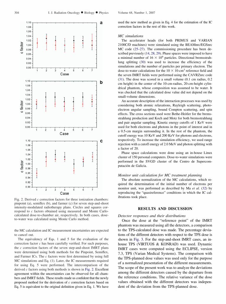
tt
ctwaMfdabpE
uc
M
2Msalsdt(cdws
ceesauacrra
cpp
M
qmri
D
pttshI7toTatv
Fpirct
304 I. J. Radiation Oncology ● Biology ● Physics Volume 68, Number 1, 2007
he MC calculation and IC measurement uncertainties are expectedo cancel out.
The equivalency of Eqs. 1 and 5 for the evaluation of theorrection factor c has been carefully verified. For such purposes,he c correction factors of the seven step-and-shoot IMRT plansere determined using both methods for the Pinpoint, Semiflex,
nd Farmer ICs. The c factors were first determined by using fullC simulations and Eq. (1). Later, the IC measurements required
or using Eq. 5 were performed. The intercomparison of theerived c factors using both methods is shown in Fig. 2. Excellentgreement within the uncertainties can be observed for all cham-ers and IMRT fields. These results made us confident that the newlyroposed method for the derivation of c correction factors based on
ig. 2. Derived c correction factors for three ionization chambers:inpoint (a), semiflex (b), and farmer (c) for seven step-and-shootntensity-modulated radiotherapy plans. Circles and squares cor-espond to c factors obtained using measured and Monte Carlo-alculated dose-to-chamber air, respectively. In both cases, dose-o-water was calculated using Monte Carlo method.
q. 5 is equivalent to the original definition given in Eq. 1. We have d
sed the new method as given in Eq. 4 for the estimation of the ICorrection factors in the rest of this work.
C simulationsThe accelerator heads (for both PRIMUS and VARIAN
100C/D machines) were simulated using the BEAMnrc/EGSnrcC code (25–27). The commissioning procedure has been de-
cribed previously (14, 28, 29). Phase spaces were imposed to haveminimal number of 16 � 106 particles. Directional bremsstrah-
ung splitting (30) was used to increase the efficiency of theimulations and the number of particles per primary electron. Theose-to-water calculations for the 10 � 10-cm2 reference field andhe seven IMRT fields were performed using the CAVRZnrc code31). The dose was scored in a small volume (0.1 cm radius, 0.2m height) in the center of the 10-cm-radius, 20-cm-height cylin-rical phantom, whose composition was assumed to be water. Itas checked that the calculated dose value did not depend on the
mall-volume dimensions.An accurate description of the interaction processes was used by
onsidering both atomic relaxations, Rayleigh scattering, photo-lectron angular sampling, bound Compton scattering, and spinffects. The cross sections used were Bethe-Heitler for the brems-trahlung production and Koch and Motz for both bremsstrahlungnd pair angular sampling. Kinetic energy cutoffs of 1 KeV weresed for both electrons and photons in the point of interest and in0.5-cm margin surrounding it. In the rest of the phantom, the
utoff energy was 10 KeV and 200 KeV for photons and electrons,espectively. To increase the simulation efficiency, we used rangeejection with a cutoff energy of 2.0 MeV and photon splitting withfactor of 20.Phase space calculations were done using an in-house Linux
luster of 150 personal computers. Dose-to-water simulations wereerformed in the SVGD cluster of the Centro de Supercom-utación de Galicia.
onitor unit calculation for MC treatment planningThe absolute normalization of the MC calculations, which re-
uired the determination of the initial number of electrons peronitor unit, was performed as described by Ma et al. (32) by
eproducing the “quasireference” conditions in which the IC cal-brations took place.
RESULTS AND DISCUSSION
etector responses and their distributionsOnce the dose at the “reference point” of the IMRT
hantom was measured using all the detectors, a comparisono the TPS-calculated dose was made. The percentage devia-ions of the different detectors with respect to the TPS dose ishown in Fig. 3. For the step-and-shoot IMRT cases, an in-ouse TPS (VIRTUOS & KONRAD) was used. DynamicMRT cases were computed using the ECLIPSE, version.3, TPS (Varian Medical Systems). The comparison withhe TPS-planned dose values was used only for the purposef a normalized presentation of the different measurements.he scope of the present work was to analyze the deviationsmong the different detectors caused by the departure fromhe reference conditions. The relative variance of the dosealues obtained with the different detectors was indepen-
ent of the deviation from the TPS-planned dose.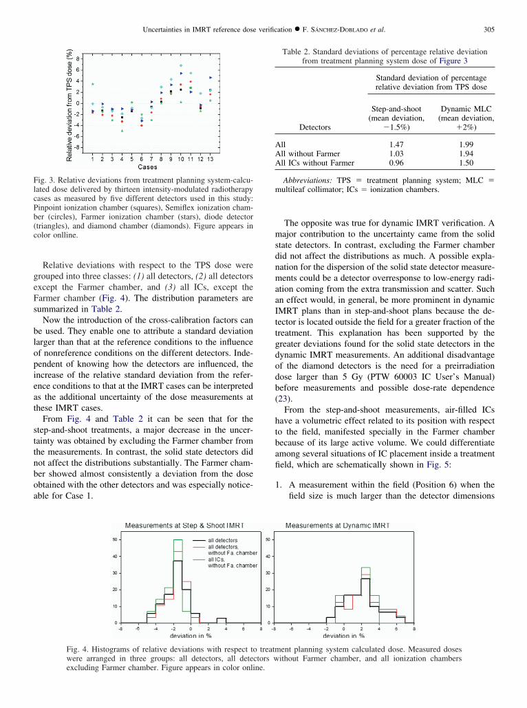
geFs
blopieat
sttnboa
msdnmaaIttgdodb(
htbafi
1
FlcPb(c
AAA
m
305Uncertainties in IMRT reference dose verification ● F. SÁNCHEZ-DOBLADO et al.
Relative deviations with respect to the TPS dose wererouped into three classes: (1) all detectors, (2) all detectorsxcept the Farmer chamber, and (3) all ICs, except thearmer chamber (Fig. 4). The distribution parameters areummarized in Table 2.
Now the introduction of the cross-calibration factors cane used. They enable one to attribute a standard deviationarger than that at the reference conditions to the influencef nonreference conditions on the different detectors. Inde-endent of knowing how the detectors are influenced, thencrease of the relative standard deviation from the refer-nce conditions to that at the IMRT cases can be interpreteds the additional uncertainty of the dose measurements athese IMRT cases.
From Fig. 4 and Table 2 it can be seen that for thetep-and-shoot treatments, a major decrease in the uncer-ainty was obtained by excluding the Farmer chamber fromhe measurements. In contrast, the solid state detectors didot affect the distributions substantially. The Farmer cham-er showed almost consistently a deviation from the dosebtained with the other detectors and was especially notice-ble for Case 1.
ig. 3. Relative deviations from treatment planning system-calcu-ated dose delivered by thirteen intensity-modulated radiotherapyases as measured by five different detectors used in this study:inpoint ionization chamber (squares), Semiflex ionization cham-er (circles), Farmer ionization chamber (stars), diode detectortriangles), and diamond chamber (diamonds). Figure appears inolor onlline.
Fig. 4. Histograms of relative deviations with respect towere arranged in three groups: all detectors, all detec
excluding Farmer chamber. Figure appears in color online.The opposite was true for dynamic IMRT verification. Aajor contribution to the uncertainty came from the solid
tate detectors. In contrast, excluding the Farmer chamberid not affect the distributions as much. A possible expla-ation for the dispersion of the solid state detector measure-ents could be a detector overresponse to low-energy radi-
tion coming from the extra transmission and scatter. Suchn effect would, in general, be more prominent in dynamicMRT plans than in step-and-shoot plans because the de-ector is located outside the field for a greater fraction of thereatment. This explanation has been supported by thereater deviations found for the solid state detectors in theynamic IMRT measurements. An additional disadvantagef the diamond detectors is the need for a preirradiationose larger than 5 Gy (PTW 60003 IC User’s Manual)efore measurements and possible dose-rate dependence23).
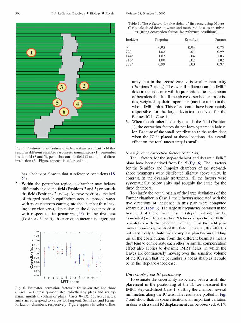
From the step-and-shoot measurements, air-filled ICsave a volumetric effect related to its position with respecto the field, manifested specially in the Farmer chamberecause of its large active volume. We could differentiatemong several situations of IC placement inside a treatmenteld, which are schematically shown in Fig. 5:
. A measurement within the field (Position 6) when thefield size is much larger than the detector dimensions
ent planning system calculated dose. Measured dosesithout Farmer chamber, and all ionization chambers
Table 2. Standard deviations of percentage relative deviationfrom treatment planning system dose of Figure 3
Detectors
Standard deviation of percentagerelative deviation from TPS dose
Step-and-shoot(mean deviation,
�1.5%)
Dynamic MLC(mean deviation,
�2%)
ll 1.47 1.99ll without Farmer 1.03 1.94ll ICs without Farmer 0.96 1.50
Abbreviations: TPS � treatment planning system; MLC �ultileaf collimator; ICs � ionization chambers.
treatmtors w
2
3
N
pfscst
Ffisfiabunutelob
U
pIm7
F(nai
Frii
07122
306 I. J. Radiation Oncology ● Biology ● Physics Volume 68, Number 1, 2007
has a behavior close to that at reference conditions (18,21).
. Within the penumbra region, a chamber may behavedifferently inside the field (Positions 3 and 5) or outsidethe field (Positions 2 and 4). At these positions, the lackof charged particle equilibrium acts in opposed ways,with more electrons coming into the chamber than leav-ing it or vice versa, depending on the detector positionwith respect to the penumbra (22). In the first case(Positions 3 and 5), the correction factor c is larger than
ig. 6. Estimated correction factors c for seven step-and-shootCases 1–7) intensity-modulated radiotherapy plans and six dy-amic multileaf collimator plans (Cases 8–13). Squares, circles,nd stars correspond to values for Pinpoint, Semiflex, and Farmer
ig. 5. Positions of ionization chamber within treatment field thatesult in different chamber responses: transmission (1), penumbranside field (3 and 5), penumbra outside field (2 and 4), and directrradiation (6). Figure appears in color online.
ionization chambers, respectively. Figure appears in color online.
unity, but in the second case, c is smaller than unity(Positions 2 and 4). The overall influence on the IMRTdose at the isocenter will be proportional to the amountof beamlets that fulfill the above-described characteris-tics, weighted by their importance (monitor units) in thewhole IMRT plan. This effect could have been mainlyresponsible for the large deviation observed for theFarmer IC in Case 1.
. When the chamber is clearly outside the field (Position1), the correction factors do not have systematic behav-ior. Because of the small contribution to the entire dosewhen the IC is placed at these locations, the overalleffect on the total uncertainty is small.
onreference correction factors (c factors)The c factors for the step-and-shoot and dynamic IMRT
lans have been derived from Eq. 5 (Fig. 6). The c factorsor the Semiflex and Pinpoint chambers of the step-and-hoot treatments were distributed slightly above unity. Inontrast, in the dynamic treatments, all the factors wereystematically below unity and roughly the same for thehree chambers.
To clarify the actual origin of the large deviations of thearmer chamber in Case 1, the c factors associated with theve directions of incidence in this plan were computedeparately (Table 3). The large discrepancies obtained in therst field of the clinical Case 1 (step-and-shoot) can bessociated (see the subsection “Detailed inspection of IMRTeamlets”) with the placement of the IC in the field pen-mbra in most segments of this field. However, this effect isot very likely to hold for a complete plan because addingp all the contributions from the different beamlets meanshey tend to compensate each other. A similar compensationffect also applies to dynamic IMRT fields, in which theeaves are continuously moving over the sensitive volumef the IC, such that the penumbra is not as sharp as it coulde in the step-and-shoot case.
ncertainty from IC positioningTo estimate the uncertainty associated with a small dis-
lacement in the positioning of the IC we measured theMRT step-and-shoot Case 1, shifting the chamber severalillimeters along the IC axis. The results are plotted in Fig.and show that, in some situations, an important variation
Table 3. The c factors for five fields of first case using MonteCarlo-calculated dose-to-water and measured dose-to-chamber
air (using conversion factors for reference conditions)
Incident Pinpoint Semiflex Farmer
° 0.95 0.93 0.752° 1.02 1.01 0.9944° 1.02 1.04 1.0316° 1.00 1.02 1.0288° 0.99 1.00 0.97
n dose with a small IC displacement can be observed. A 1%
ccb
D
dpttsifltw
MWbotr
Fctbasquares, respectively. Figure appears in color online.
for each field. Figure appears in color online.
307Uncertainties in IMRT reference dose verification ● F. SÁNCHEZ-DOBLADO et al.
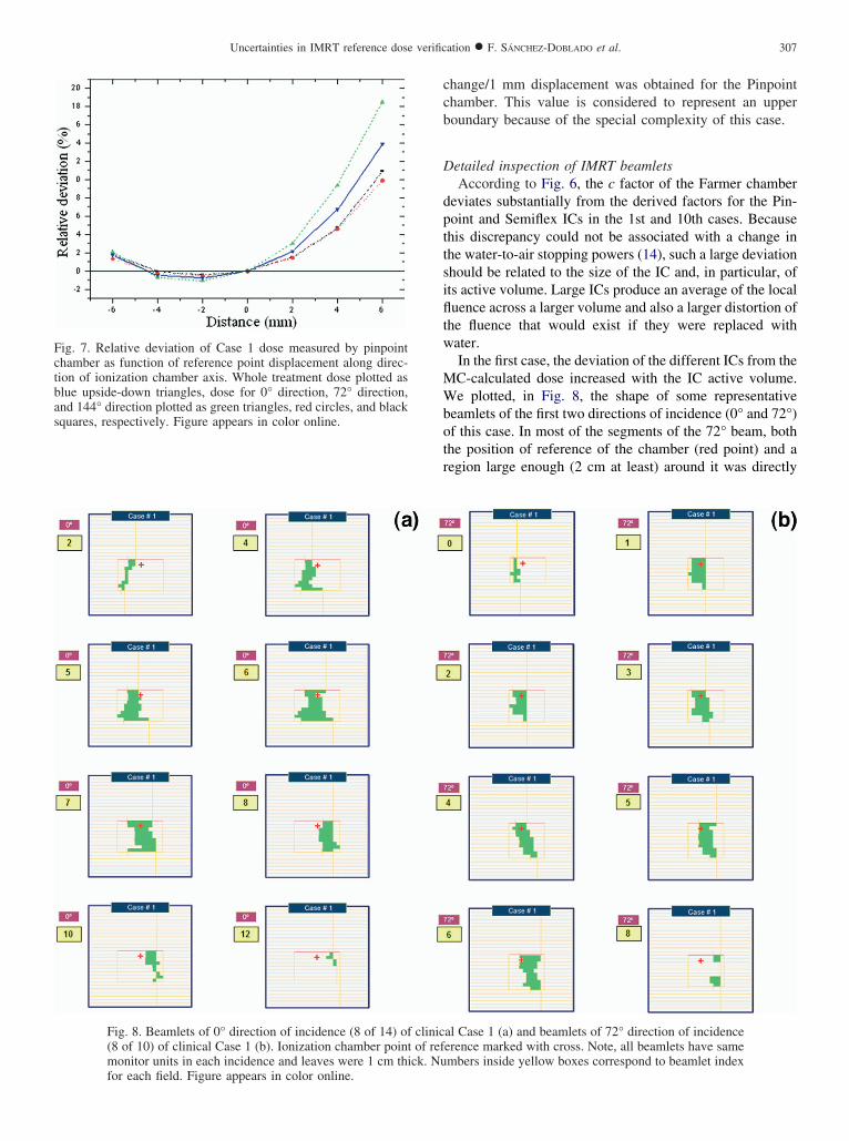
hange/1 mm displacement was obtained for the Pinpointhamber. This value is considered to represent an upperoundary because of the special complexity of this case.
etailed inspection of IMRT beamletsAccording to Fig. 6, the c factor of the Farmer chamber
eviates substantially from the derived factors for the Pin-oint and Semiflex ICs in the 1st and 10th cases. Becausehis discrepancy could not be associated with a change inhe water-to-air stopping powers (14), such a large deviationhould be related to the size of the IC and, in particular, ofts active volume. Large ICs produce an average of the localuence across a larger volume and also a larger distortion of
he fluence that would exist if they were replaced withater.In the first case, the deviation of the different ICs from theC-calculated dose increased with the IC active volume.e plotted, in Fig. 8, the shape of some representative
eamlets of the first two directions of incidence (0° and 72°)f this case. In most of the segments of the 72° beam, bothhe position of reference of the chamber (red point) and aegion large enough (2 cm at least) around it was directly
al Case 1 (a) and beamlets of 72° direction of incidenceerence marked with cross. Note, all beamlets have samembers inside yellow boxes correspond to beamlet index
ig. 7. Relative deviation of Case 1 dose measured by pinpointhamber as function of reference point displacement along direc-ion of ionization chamber axis. Whole treatment dose plotted aslue upside-down triangles, dose for 0° direction, 72° direction,nd 144° direction plotted as green triangles, red circles, and black
Fig. 8. Beamlets of 0° direction of incidence (8 of 14) of clinic(8 of 10) of clinical Case 1 (b). Ionization chamber point of refmonitor units in each incidence and leaves were 1 cm thick. Nu
iacwthp“btr
ubrmcTttadatp
d
ssudisvvte
fshibt
imele
igure
308 I. J. Radiation Oncology ● Biology ● Physics Volume 68, Number 1, 2007
rradiated. Only in 2 of 10 beamlets was the chamber placedt the edge of the field or completely shadowed by theollimator. The 0° beam represents the opposite situation inhich, in most of the segments, the chamber is placed close
o the edges of the fields and only 1 segment of 14 directlyits the IC. Considering the discussion of the effects of IClacement with respect to the field edges (see the subsectionDetector responses and their distributions”) on the cham-er response, the origin of the discrepancies observed withhe Farmer chamber is a secondary electron flux unbalanceesulting from being placed in the field penumbra.
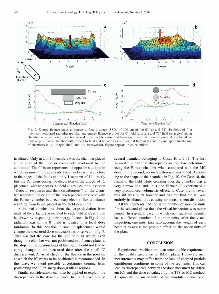
Additional conclusions about the large deviation fromnity of the c factors associated to each field in Case 1 cane drawn by inspecting their energy fluence. In Fig. 9, theadiation axis of the 0° field is located in a local doseinimum. In this position, a small displacement would
hange the measured dose noticeably, as observed in Fig. 7.his was not the case for the 72° field, in which, even
hough the chamber was not positioned in a fluence plateau,he slope in the surroundings of this point would not lead to
big change in the measured dose after the small ICisplacement. A visual check of the fluence in the positiont which the IC wants to be positioned is recommended. Inhis way, we avoid possible uncertainties coming fromositioning the IC in sharp dose-gradient regions.Similar considerations can also be applied to explain the
Fig. 9. Energy fluence maps at source surface distancintensity-modulated radiotherapy plan and energy fluencchamber axis direction (c) and transversal direction (d) nrelative position of chamber with respect to field and radof chambers in (c) (longitudinal) and (d) (transversal). F
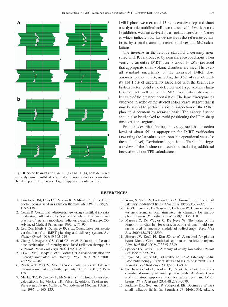
iscrepancies in the dynamic cases. In Fig. 10, we plotted T
everal beamlets belonging to Cases 10 and 11. The firsthowed a substantial discrepancy in the dose determinedsing the Farmer chamber when compared with the MCose. In the second, no such difference was found. Accord-ng to the shape of the beamlets in Fig. 10, for Case 10, thehape of the field while crossing over the chamber was aery narrow slit, and, thus, the Farmer IC experienced aery pronounced volumetric effect. In Case 11, however,his slit was much broader and ensured that the IC wasntirely irradiated, thus causing no measurement distortion.
All the segments had the same number of monitor unitsor the selected plans; thus, the visual inspection was ratherimple. In a general case, in which each radiation beamletas a different number of monitor units, after the visualnspection, one must take into account the weight of eacheamlet to assess the possible effect on the uncertainty ofhe plan.
CONCLUSION
Experimental verification is an unavoidable requirementn the quality assurance of IMRT plans. However, sucheasurements may suffer from the lack of charged particle
quilibrium conditions in some of the segments. This canead to discrepancies between the dose measured by differ-nt ICs and the dose calculated by the TPS or MC method.
) of 100 cm of the 0° (a) and 72° (b) fields of firstles for 0° field (crosses) and 72° field (triangles) alonged to energy fluence at reference point. Also plotted areaxis (thick red line) in (a) and (b) and approximate sizeappears in color online.
e (SSDe profi
ormaliziation
o quantify the uncertainty of the absolute dosimetry of
IaIctl
svtaaibbbompsd
l(tai
REFEREN
ing, 1995. p. 103–135.
1
1
1
1
1
1
Fuchamber point of reference. Figure appears in color online.
309Uncertainties in IMRT reference dose verification ● F. SÁNCHEZ-DOBLADO et al.
MRT plans, we measured 13 representative step-and-shootnd dynamic multileaf collimator cases with five detectors.n addition, we also derived the associated correction factors, which indicate how far we are from the reference condi-ions, by a combination of measured doses and MC calcu-ations.
The increase in the relative standard uncertainty mea-ured with ICs introduced by nonreference conditions whenerifying an entire IMRT plan is about 1–1.5%, providedhat appropriate small-volume chambers are used. The over-ll standard uncertainty of the measured IMRT dosemounts to about 2.3%, including the 0.5% of reproducibil-ty and 1.5% of uncertainty associated with the beam cali-ration factor. Solid state detectors and large volume cham-ers are not well suited to IMRT verification dosimetryecause of the greater uncertainties. The large discrepanciesbserved in some of the studied IMRT cases suggest that itay be useful to perform a visual inspection of the IMRT
lan on a segment-by-segment basis. The energy fluencehould also be checked to avoid positioning the IC in sharpose-gradient regions.From the described findings, it is suggested that an action
evel of about 5% is appropriate for IMRT verificationassuming the 2� value as a reasonable operational value forhe action level). Deviations larger than �5% should trigger
review of the dosimetric procedure, including additionalnspection of the TPS calculations.
CES
1. Lovelock DM, Chui CS, Mohan R. A Monte Carlo model ofphoton beams used in radiation therapy. Med Phys 1995;22:1387–1394.
2. Curran B. Conformal radiation therapy using a multileaf intensitymodulating collimators. In: Sternic ES, editor. The theory andpractice of intensity modulated radiation therapy. Durango, CO:Advanced Medical Publishing, 1997. p. 75–90.
3. Low DA, Mutic S, Dempsey JF, et al. Quantitative dosimetricverification of an IMRT planning and delivery system. Ra-diother Oncol 1998;49:305–316.
4. Chang J, Mageras GS, Chui CS, et al. Relative profile anddose verification of intensity-modulated radiation therapy. IntJ Radiat Oncol Biol Phys 2000;47:231–240.
5. Li XA, Ma L, Naqvi S, et al. Monte Carlo dose verification forintensity-modulated arc therapy. Phys Med Biol 2001;46:2269–2282.
6. Pawlicki T, Ma CM. Monte Carlo simulation for MLC-basedintensity-modulated radiotherapy. Med Dosim 2001;26:157–168.
7. Mackie TR, Reckwerdt P, McNutt T, et al. Photon beam dosecalculations. In: Mackie TR, Palta JR, editors. Teletherapy:Present and future. Madison, WI: Advanced Medical Publish-
8. Wang X, Spirou S, LoSasso T, et al. Dosimetric verification ofintensity modulated fields. Med Phys 1996;23:317–328.
9. De Vlamynck K, De Wagter C, De Neve W. Diamond detec-tor measurements near simulated air channels for narrowphoton beams. Radiother Oncol 1999;53:155–159.
0. Martens C, De Wagter C, De Neve W. The value of thePinpoint ion chamber for characterization of small field seg-ments used in intensity-modulated radiotherapy. Phys MedBiol 2000;45:2519–2530.
1. Siebers JV, Keall PJ, Kim JO, et al. A method for photonbeam Monte Carlo multileaf collimator particle transport.Phys Med Biol 2002;47:3225–3249.
2. Spencer LV, Attix FH. A theory of cavity ionization. RadiatRes 1955;3:239–254.
3. Boyer AL, Butler EB, DiPetrillo TA, et al. Intensity-modu-lated radiotherapy: Current status and issues of interest. Int JRadiat Oncol Biol Phys 2001;51:880–914.
4. Sánchez-Doblado F, Andreo P, Capote R, et al. Ionizationchamber dosimetry of small photon fields: A Monte Carlostudy on stopping-power ratios for radiosurgery and IMRTbeams. Phys Med Biol 2003;48:2081–2099.
5. Paskalev KA, Seutjens JP, Podgorsak EB. Dosimetry of ultra
ig. 10. Some beamlets of Case 10 (a) and 11 (b), both deliveredsing dynamic multileaf collimator. Cross indicates ionization
small radiation fields. In: Seuntjens JP, Mobit PN, editors.
1
1
1
1
2
2
2
2
2
2
2
2
2
2
3
3
3
310 I. J. Radiation Oncology ● Biology ● Physics Volume 68, Number 1, 2007
Proceedings of the international workshop on accurateradiation dosimetry, AAPM Proceedings Series 13. Madison,WI: Medical Physics Publishing, 2002. p. 298–318.
6. Paskalev KA, Seuntjens JP, Patrocinio HJ, et al. Physical aspects ofdynamic stereotactic radiosurgery with very small photon beams(1.5 and 3 mm in diameter). Med Phys 2002;30:111–118.
7. Verhaegen F. Evaluation of the EGSnrc Monte Carlo code forinterface dosimetry near high-Z media exposed to kilovolt and60Co photons. Phys Med Biol 2002;47:1691–1705.
8. Capote R, Sánchez-Doblado F, Leal A, et al. An EGSnrcMonte Carlo study of the microionization chamber for refer-ence dosimetry of narrow irregular IMRT beamlets. Med Phys2004;31:2416–2422.
9. Bouchard H, Seuntjens J. Ionization chamber-based referencedosimetry of intensity modulated radiation beams. Med Phys2004;31:2454–2465.
0. Sempau J, Andreo P, Aldana J, et al. Electron beam qualitycorrection factors for plane-parallel ionization chambers:Monte Carlo calculations using the PENELOPE system. PhysMed Biol 2004;49:4427–4444.
1. Sánchez-Doblado F, Capote R, Leal A, et al. Microionizationchamber for reference dosimetry in IMRT verification: Clin-ical implications on OAR dosimetric errors. Phys Med Biol2005;50:959–970.
2. Sánchez-Doblado F, Capote R, Leal A, et al. Micro ionizationchamber dosimetry in IMRT verification: Clinical implica-tions of dosimetric errors in the PTV. Radiother Oncol 2005;75:342–348.
3. Fidanzio A, Azario L, Miceli R, et al. A. PTW-diamonddetector: Dose rate and particle type dependence. Med Phys
2000;11:2589–2593.4. Andreo P, Burns DT, Hohlfeld K, et al. Absorbed dose deter-mination in external beam radiotherapy: An InternationalCode of Practice for dosimetry based on standards of absorbeddose to water. IAEA Technical Report Series No. 398. Vi-enna: International Atomic Energy Agency, 2000.
5. Rogers DWO, Faddegon BA, Ding GX, et al. BEAM: AMonte Carlo code to simulate radiotherapy treatment units.Med Phys 1995;22:503–524.
6. Rogers DWO, Kawrakow I. The EGSnrc Code System: MonteCarlo simulation of electron and photon transport. Technicalreport PIRS-701. Ottawa: National Research Council of Can-ada; 2000.
7. Kawrakow I. Accurate condensed history Monte Carlo simu-lation of electron transport. I. EGSnrc, the new EGS4 version.Med Phys 2000;27:485–498.
8. Leal A, Sánchez-Doblado F, Arráns R, et al. Routine IMRTverification by means of an automatic MC simulation system.Int J Radiat Oncol Phys 2003;65:58–68.
9. Lagares JI, Leal A, Sánchez-Doblado F, et al. Dynamic IMRTsegment optimisation for a faster MC verification [Abstract].Radiother Oncol 2003;68(Suppl. 1):S91–S92.
0. Kawrakow I, Rogers DWO, Walters BRB. Large efficiencyimprovements in BEAMnrc using directional bremsstrahlungsplitting. Med Phys 2004;31:2883–2898.
1. Rogers DWO, Kawrakow I, Seuntjens JP, et al. NRC usercodes for EGSnrc. Technical report PIRS-702 revB. Ottawa:National Research Council of Canada; 2003.
2. Ma C-M, Price RA Jr., Li JS, et al. Monitor unit calculationfor Monte Carlo treatment planning. Phys Med Biol 2004;49:
1671–1687.