Embed Size (px)
Citation preview

UNCLASSIFIED
AD 405 756
DEFENSE DOCUMENTATION CENTERFOR
SCIENTIFIC AND TECHNICAL INFORMATION
CAMERON STATION, ALEXANDRIA. VIRGINIA
UNCLASSIFIED

NOTICE: Nhen government or other drawings, speci-fications or other data are used for any purposeother than in connection with a definitely relatedgovernment procurement operation, the U. S.Government thereby incurs no responsibility, nor anyobligation whatsoever; and the fact that the Govern-ment may have formilated., furnished, or in any waysupplied the said drawings, specifications, or otherdata is not to be regarded by implication or other-wise as in any manner licensing the holder or anyother person or corporation, or conveying any rightsor permission to manufacture, use or sell anypatented invention that may in any way be relatedthereto.

AA
DDC
JUN 9 1963
Ti z:I
MAKWYWRýIlALS&*V...) ;ff,

!NE 4W AXAA COMPANY
CODE IDENT NO. 81205
NUMBER D2-14934-
TITLE WS-133A Maintah~abilitv Progress Rev rt ( )
MODEL No, WS-133A _CONTRACT No. AF04(648)-289
ISSUE NO. ..ZZ.....ISSUED TO •I/A iC
1111CIAL LUMITATIOM WS AM^ AItASTBIMUflCs#
= 7I e 4*bt I e~ to ,.dudift doefsuui vsbsd W d u.is v geuuus "CNN02omm -p e~e e"d of Imom ow go
C) UIMIDU-To V. L mO*"1 wgeds*Ot6u .016Ibis P~~ "e be AAKWtsd to -- Af"~e. egmges. o"t -pps~ - e..sbiset ft Seeng ppp WSJ q f .. b reWqest.
LNWWI: Me MUM u-too" "e be .b..b.e ed be.w#eem a or libel j ltidp@ti. pegelsty. "Mcotl. duli S IWW alees,
PREARED BY 344L&IfEarl Hard '
SUPEISE By----_-- ______ k . '3Ig i. 3
APPROVED BY6
W. A.COLO(DATE)
REYSYM VOL NOO
I$KcT. PAe4

ACTIVE PAGE RECORD
ADDED PAGES ADDED PAGES
P 0 ý c; ui uLZ 0i 2 ýZ
1 3824.1. 393 404 41
.. 5 42
1. 6 432. 443. 454. 7 46
8 479 4810 49
5. 11 5012 51
6. 13 5214 5315 54.16 5517 5618 5719 5820 5921 6022 6123 6224 6325 6426 6527 6628 ."729 6830 6931 7032 7133 7234 7335 /7436 7537 76
U2 4601 0600 ORiO. 6/4I 16ll4634
IREV SYM__,_, •z,~ NO , D2-14934-3
SacT. PAcm 2

Wý-ACTIVE PAGE RECORD_jADDEDPAE
PADDGPGE
Ic~~ >tý;0 u -E :QQ.Z ~ ~ ~ L >u 0 ; 0; tu- 0C
in 0>2 Uu93 -cz> C
"Q'vo 0O D2.>.0c; > cc;3SECT IPA 24 < u
FOREWORD
This document, D2-14934-3, entitled "WS-133AMaintainability Progress Report", is submitted toBSD/STL in accordance with the requirementsof Technical Directive 62-4488, "MaintainabilityRequirement Program," dated 28 May 1962.
(
NANV LZi NO. D2-14934-3
PAS3

REFERENCES
a. MIL-M-26512B, "Maintainability Requirements for AerospaceSystems and Equipment," dated 23 March 1962.
b. 6120-7822-DU-RDI, "Maintainability Criteria, Preliminary," dated 16March 1962.
c. T.D. 62-4488, "Maintainability Requirements Program", dated 28May 1962.
d. CCN 448, dated 28 May 1962.
e. CCP 803, dated 5 October 1962.
f. D2-14475 "WS-133A Maintainability Program Plan."
g. D2-4747-1, "Maintainability Design Criteria for MinutemanElectronic Equipment."
h. D2-4747-2, "Maintainability Design Criteria for MinutemanTransportation and Handling Equipment."
L D2-4747-3, "Maintainability Design Criteria for Minuteman Facilitiesand Facilities Equipment."
J. Boeing letter 2-5261-2-249, dated December 20, 1962, with enclosure,"List of WS-133A Equipment Selected for Maintainability Demonstrations."
ih. D2-14256 "Minuteman _kintainability Guide for Design Criteria."
"16M., P,.A9...,, NO. D2-14934-3
PASI 4

TABLE OF CONTENTS
PAGE
i FOREWORD 3
ii REFERENCES 4
iii TABLE OF CONTENTS 5
LO SCOPE 6
2.0 PURPOSE 6
3.0 INTRODUCTION 6
4.0 MAINTAINABILITY REVIEW AND EVALUATION 7
4.1 MAINTAINABILITY REVIEWS 7
4.2 MAINTAINABILITY ACTION REQUESTS (MAR) 9
4.3 MAINTAINABILITY REVIEW REPORTS (MRR) 9
4.4 FIELD LIAISON REPORTS 10
5.0 MAINTAINABILITY TEST AND DEMONSTRATION 1
5.1 TEST AND DEMONSTRATION PLAN 1
5.2 TEST AND DEMONSTRATION EQUIPMENT LIST 1
5.3 MAINTAINABILITY EVALUATION/OBSERVATION 12(E/O) REPORTS
6.0 REPORTS 13
6.1 MAINTAINABILITY REVIEW STATUS SUMMARY 13
6.2 MAR STATUS SUMMARY 15
6.3 DEMONSTRATION REQUIREMENTS STATUS SUMMARY 21
6.4 CURRENT FVALUATION/OBSERVATION (E/O) REPORTS 57
I."B
.ffEG IiNO. D2-14934-3
tASI 5

LO SCOPE
This document constitutes The Boeing Company's monthly statusreport to the Air Force on Maintainability Activities pertaining tothe WS-133A Minuteman Weapon System. The MaintainabilityProgram is a contractual obligation of The Boeing Company underCCN 448 of Contract Number AF04(648)-289.
2.0 PURPOSE
The Air Force has requested that The Boeing Company developMaintainability Criteria and conduct a Maintainability Program inaccordance with this criteria. This is being accomplished inaccordance with the WS-133A Maintainability Program Plan (D2-14475)based on the requirements set forth in MIL-M-26512B as amendedby Technical Directive 62-4488.
The purpose of this document is to report to the appropriateAir Force agencies the progress achieved in execution of theMaintainability Plan and to detail the work accomplished during thereporting period.
3.0 INTRODUCTION
This document is the third of the monthly reports that outline theprogress achieved by the contractor in the WS-133A MaintainabilityProgram. The first report covered the period from 18 October 1962thru 31 December 1962. Each succeeding report covers a monthlyperiod from the first thru the last day of each month. This reportcovers the month of February, 1963.
The Maintainability Program Plan for the Minuteman WeaponSystem is two-fold; it provides both a Design Review and EvaluationPlan and a Test and Demonstration Plan. The monthly reportscontaitr status of progress and problem areas encountered in eachof these plans.
° 47 . D2-14934-S
PAGE 6

4.0 MAINTAINABILITY REVIEW AND EVALUATION
4.1 MAINTAINABILITY REVIEWS
4.1.1 Program
As part of the Maintainability (M) effort under CCP-803 and theWS-133A Maintainability Progrim Plan (D2-14475), specific figure"A" items are being reviewed for M and soldering in accordancewith criteria as specified in 6120-7-822-DU-RDI. Major Mproblem areas revealed by these reviews are reported throughInitiation of a Maintainability Action Request (MAR). Minor Mproblems of the product improvement type are reported to theDesign Project through a Maintainability Review Report (MRR).
4.1.2 Figure "A" Items To Be Reviewed
a. The following figure "A" items were selected by the customerfor M review:.
1) 1207 Drier, Air Compressor;
2) 1281 Fault Locator Set, AN/GSM-69;
3) 1288 Battery, Storage;
4) 1337 Distribution Box;
5) 1338 Console, Communications Control;
6) 1367 Motor/Generator, PU-521;
7) 1380 Distribution Box;
8) 1385 Distribution Box;
9) 1412 Signal Assembly, Voice Reporting;
10) 1423 Antenna Group, AN/GRA-72;
11) 1424 Antenna, AS-1213/GRC-113;
12) 1425 Antenna System, H.F., Receiving & Transmitting;
13) 1426 Antenna, ILF., Transmitting, Hardened;.
no. D2-14934-3
PAGSE 7

4.1.2 (Continued)
14) 1607 Security and Alarm Set;
15) 3007 Test-set, Explosive Set Circuitry;
16) 3092 Test-set, Programmer Group;
17) 4018 Adapter AN/GSM-61;
18) 4043 Elevator, Work Cage;
19) 4152 Test Equipment; Electrical Facility, BaseMaintenance;
20) 4220 Test-Set, Relay;
21) 4252 CIV Set, AN/GSQ-65;
22) 4344 Fault Locator, SCN Cable;
23) 4451 Controller, Azimuth.Drive;
24) 4487 Command Signal Simulator;
25) 4489 Message Generator;
26) 4490 Simulator Set, Electrical Functions;
27) 4491 Start-Up Unit;
28) 4515 Static Frequency Changer;
29) 4523 Common Power Supply;
30) 4539 Test-Set, VRSA;
31) 4601 Function Simulator; H.F./UHF Radio;
32) 4632 Test-Set. Electric Power, LF;
33) 4633 Test-Set, Electric Power, LCF.
b. The Minutes of the Maintainability Review Meetings held atBoeing on 9 January 1962, and at RCA, on 16 January 1962 (file
Pic D2-14934-•

4.1.2 (Continued)
No. 2-6331-0-366, dated 7 February 1962) listed certain figure"A" items which were not reviewed due to non-availability ofhardware. These items are being reviewed on a schedulecompatible with equipment availability.
c. Other figure "A" items are being reviewed as problem areasare identified by review of Field Service Reports, System TestAction Requests, Unsatisfactory Reports, M Evaluation/Observa-tion (E/O) Reports, and other field reports prepared by Boeingorganizations.
4.2 MAINTAINABILITY ACTION REQUESTS (MAR)
Status of all MAR's initiated to date is contained in the MARStatus Summary Chart (See Section 6.2).
4.3 MAINTAINABILITY REVIEW REPORTS (MRR)
During the reporting period MRR's on the following equipmentswere completed:
a) Test Adapter Group, Figure A 4018;
b) L.F. Start-up Unit, Figure A 4491;
c) Programmer Group Test Set, Figure A 3092;
d) Simulator Set, Missile Launch, Figure A 4490;
The MRR's have been forwarded to the cognizant design groupfor consideration as product improvement items. (See Maintain-ability Review Status Summary Chart Section 6.1).
3067i N. O [ D2-14934-3

4.4 FIELD LIAISON REPORTS
Surveillance of operational activities to obtain additional Maintain-ability data is being accomplished thru review of STAR's(Systems Test Action Requests), FSR's (Field Service Reports),UR's (Unsatisfactory Reports), and BIAR's (Base InstallationAction Requests)., During the reporting period, four (4) STAR's,four (4) FSR's, and three (3) BIAR's have been reviewed forMaintainability implications.
4.4.1 MAINTAINABILITY SURVEILLANCE
In those cases where reviews indicate a maintainability problem,M Engineers are assigned to work the solutions with design. Ifthe proposed solutions to problems reported thru the above FieldLiaison Reports do not satisfy maintainability requirements thena MAR or MRR will be initiated as appropriate.
N ,'" [ N°D2- 1 4 9 3 4 -3
VA6* 10

5.0 MAINTAINABILITY TEST AND DEMONSTRATION
5.1 TEST AND DEMONSTRATION PLAN
a. Tests and performance already scheduled for other purposesat the STP II installation, Vandenberg Air Force Base, andMinuteman Wing installation are being utilized to provide asmany Maintainability demonstrations as possible. Maintain-ability Engineers are participating in those tests anddemonstrations which have inherent Maintainability significance,and are documenting their observations.
b. Items of equipment whose Maintainability features have amajor impact upon the operation and maintenance of the WeaponSystem have been selecteo. Only demonstrations involvingthese items are being documented, pending both BSD approvalof the equipment list and contractual coverage for any additionaltests considered necessary by the Customer.
5.2 TEST AND DEMONSTRATION EQUIPMENT LIST
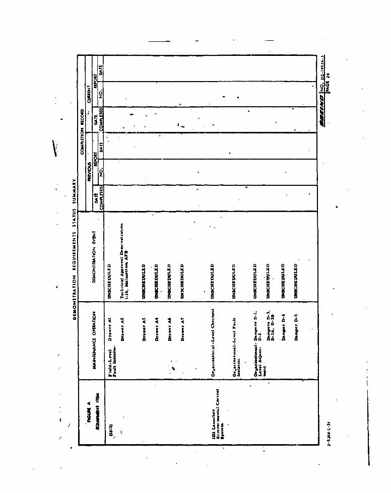
a. The "List of WS-133A Equipment Selected for MaintainabilityDemonstrations" was transmitted to BSD by letter 2-5261-2-249,dated December 20, 1962. This list identified applicablemaintenance operations which may be observed during remainingscheduled test and demonstration activities, to provide Maintain-ability demonstrations of the selected Figure "A" equipmentitems. It also identified, for each selected equipment item, thosemaintenance operations which should be demonstrated but werenot at that time known to be included within any scheduled testor demonstration.
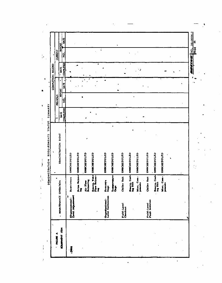
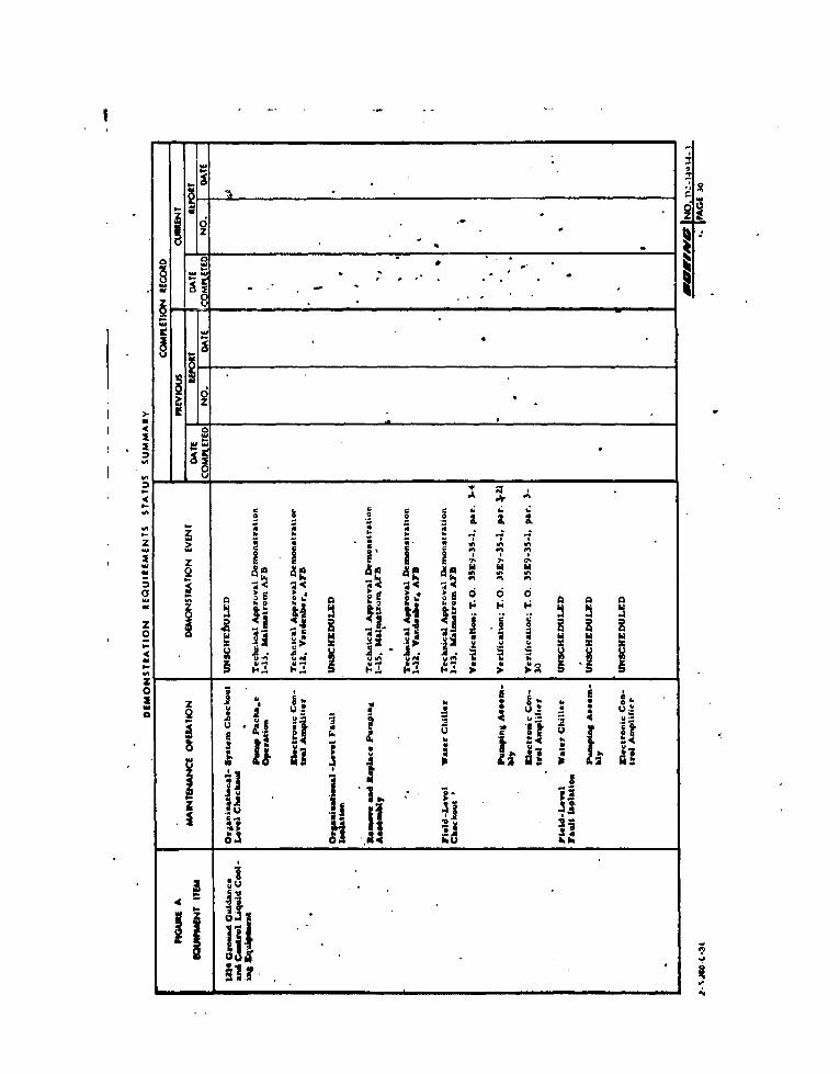
b. The "Demonstration Requirements Status Summary" (Section 6.3of this report) provides monthly amplification and updating ofthe "List of WS-133A Equipment selected for MaintainabilityDemonstrations." It contains a tabulation of the maintenanceoperations which should be demonstrated for each selected"Figure A" equipment item, and identifies any scheduled eventswhich are known to include these operations. It also containsa completion record, which provides completion dates andobserver report numbers for all demonstrations which have beenaccomplished during current and previous reporting periods.
c. Maintainability Engineers will continue to participate in theseheduled demonstration events listed in the "DemonstrationRequirements Status Summary," pending further direction fromBSD.
4o D2-14934-3
MCAI 11

5.3 MAINTAINABILITY EVALUATION/OBSERVATION (E/O) REPORTS
E/O Reports are prepared for both "dynamic" observations ofmaintenance and "static" evaluations of M design. The MaintainabilityE/O's provide the basis for subsequent irrective action on thenoted problems, and are submitted in this Progress Report as ademonstration record.
a) "Static" evaluations are complete visual inspections made on anon-interference basis whenever equipment becomes conven-iently available. "Dynamic" observations are made duringapplicable maintenance operations using actual equipment. Ineither case the E/O Reports document the demonstrationresults.
b) Each completed E/O Report is evaluated by the MaintainabilityEngineers who have Maintainability-review responsibility forthe specific "Figure A" items of equipment identified in thereport. When Maintainability deficiencies are identified in theE/O, MAR's and/or MRR's are initiated for appropriate action.
c) Twelve E/O Reports were written during the report periodcovered by this document. They were prepared by the Maintain-ability Engineers vh o participated in the M demonstrations.The reports are contained in Section 6.4
us.1)2 14934-3
I'G

6.0 REPORTS
This section contains status charts; copies of MaintainabilityAction Requests (MAR's), and Maintainability Evaluation/Observa-tion (E/O) Reports.
6.1 MAINTAINABILITY REVIEW STATUS SUMMARY
The Maintainability Review Status Chart contains an up-to-datesummary of all Figure A equipments reviewed in accordance withthe discussion contained in Section 4. As additional Figure A itemsare reviewed they will be entered on this chart with notations asto action taken and date review is completed. This chart will berevised and reproduced in each succeeding monthly status report.
m.D.mlEKA' NOxD2-14934-3 *t 13

fo o ww owW@I( oW4 0wW(
No 44 -14 C- - --4
0 z0
eq 46C v q0 CV 4C
024 0 -4- 4e*0- o)q
0 ~
en~~ 0 3
0n >
0 OA
D21*3- Page 14 b

6.2 MAR STAT'LS SUMMARY
The MAR .:tatus Chart contains up-to-date list of MAR's issuedand the current status of each MAR. Copies of MAR's will beincluded in each monthly status report until such time as they areconsidered closed.. MAR's requiring no further consideration byeither the originating engineeer or the organization responsible forcorrective action will be closed. This status is assigned by theMAR originator only when one of the following has been achieved:
a) An authorized hardware, procedure, specification or othercorrective action has been found to satisfy the MAR problem;
b) The organization responsible for action rejects the request forcorrective action and the MAR originator concurs with reasonsgiven for the rejection;
c) The MAR originator considers that the MAR requires no furtheraction because of related actions taken, events occurring, orstatus changing after initiation of the MAR.
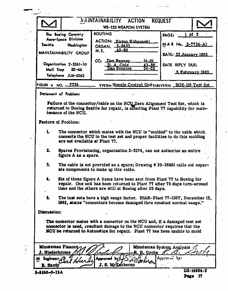
6.2.1 MAR #2-7724-Al is "closed" out for the following reasons:
1) The MAR reply from the equipment manager indicates thatthe M problem has been solved. PRR #11602 has been approvedby the Change Board.
2) The PRR eliminates the cable between the NCU and the NCUTest Set. A shorting plug, which attaches to the NCU connector,replaces the cable which was giving all the trouble.
6.2.2 MAR # 3-1282-Al is "closed" out for the following reasons:
1) The "fix" for the battery shock mounts as recommended in thisMAR is identical to a fix previously recommended in ECP-391and FCR187, which were subsequently cancelled.
2) In view of the above, Boeing considers this MAR closed unlessfurther direction is received from PSD to resubmit the ECP.
fFAW"v, "lb2 149344 *PAGE 1

.44
00
: '.,...• ......... D2-14954-3 Page 1
-4-mW'~m
NIAINTAINABILITY ACTION REQUESTWS-133 WEAPON SYSTEM
The Boeing Company ROUTING PAGE: 1 of 3Aero-Spoce Division ACTION: 1Knz.u Knh2 tCnigki
Seattle Washington ORGAN. 2-642 _M A R No. 2-7724-,lA
MAINTAINABILITY GROUP M.S. 4-93TE 22 January 1963
CC1 Inar R2nn•y 14-01Organization 2-5261-30 1) A- -nl1p 43-86 DATE REPLY DUE:
Mall Stop 50-66 Dan Su e-lee 34-03 - 1Telephone JU6-6263
FIGURE A NO. 7724 SYSTEM Nozzle Control UnItSUBSYSTEM BGS-116 Test Set
Statement of Problem:
Failure of the connector/cable on the NCTLero Alignment Test Set, which isreturned to Boeing Seattle for repair, is affecting Plant 77 capability for main-tenance of the NCU.
Factors of Problem:
L The connector which mates with the NCU is "molded" to the cable whichconnects the NCU to the test set and proper facilities to do this moldingare not available at Plant 77.
2. Spares Provisioning, organization 2-5274, can not authorize an entirefigure A as a spare.
3. The cable is not provided as a spare; Drawing # 25-26801 calls out separ-ate components to make up this cable.
4. Six of these figure A items have been sent from Plant 77 to Boeing forrepair. One unit has been returned to Plant 77 after 75 days turn-aroundtime and the others are still at Boeing after 25 days.
5. The test sets have a high usage factor. BIAR-Plant 77-130T, December 12,1962, states "connectors become damaged thru constant normal usage."
Discussion:
The connector mates with a connector on the NCU and, if a damaged test setconnector Is used, resultant damage to the NCU connector requires that theNCU be returned to Autonetics for repair. Plant 77 has been unable to mold
Minuteman Financ Minuteman Syste Anaysis .• ,
J. Nlederkrome .B Goe.M EngineweA: Aprve y pra
Be Hard J. S. d cheran.,.$ -A D2-14934-$
•Page '17

MAlR #- 2-7724-Al - Page two'
Discussion(Continued)
or pzt the connector to the cable. This molding is required because test setIs used In a hazardous area.
The current high failure rate for this test set plus the lengthy turn-aroundtime requires that a change be made in the present repair concept or thatthe quantity authorized at Plant 77 be increased for this figure A.
NOTE: Since the cost of this figure A is only 0790, increased authorizationfor this item at Plant 77 can be provided at a relative low cost; therefore acost study will not be made. The problem here is not costs but that a main-tenance bottleneck is to be prevented.
Recommendation:
Redesign of the connector/cable to make it replaceable at Plant 77.
Note:This is a preliminary cost study to assertain if the M proposal will result in asavings to the customer. Values used are gross figures and do not constituteofficial Boeing cost estimates. Their use is limited to planning purposes and tradestudies for this _M proposal.
D2-14934-3Page W8

M'WýA:NTAINABILITY ACTION REQUESTWS-133 WEAPON SYSTEM
The Boeing Co )any ROUTING PAGEs I of 2Aero-SpacO Dh% ston ACTION: J- T.- rtrum
Seattle Wo0.hlngton ORGAN. T Dnwi. Unit' M A R No. 3-1282-Al. Rev slon
MAINTAINABILITY GROUP M.S. -52-28 DATE, February 14. 1983
CC, - _ mr ,. (December 5, 1962)Organization 2-5261-30 P_ Xnenig 52-91 DATE REPLY DUEi
Mail Stop 50-66 J- M'_ Rsirktr s0-6RS-o I. A_ CnlA 43-R6Telephone JLU6-6263
FIGURE A NO. 12 R2 SYSTEM - Electrical SUBSYSTEM Storage Battery
Statement of Problem:
Difficulty is beingexperienced in Installing Launch Facility battery shockmounts at operational sites.
References:
(a) Parson Drawing SK-161
(b) FSR No MAFB 341 SMW-53F
(c) BSD Drawing SK-162
Field Service Report received from Malmstrom Air Force Base (reference b)reports considerable difficulty in installing Launcher battery shock mounts.This same difficulty can be expected whenever batteries must be moved orreplaced during the life of the weapon system.
Investigation and review of an alternate mount such as that represented by BSDdrawing SK-162 (reference c) indicates elimination of the installation andmaintenance problem. Cost studies show that due to simplicity of design, anoverall savings of approximately $655,220 can be realized. This savings isbased upon effectivity at Wing IH As the savings is approximately 1625 perLaunch Facility, it is recoLumended that this change be effected as soon aspossible.
Recommend ECP be processed to change shock mounts to ones similar to BSDdrawing SK-162 (reference c).
Minuteman Finance.A -. Minuteman Syste nysis/,.7.J- . Nederkro ,e o/ B. orobe
.M En Approved bE: AdA Approved by:R."U.S"Ph
Steam _J S.f cEs eran_______,410,,0-I SA DD2-14934-3• - Pagle 10

3-1282-Al, Revision I COST UFWTIIENESS S&1MARY Page 2 of 2
WEAPON SYSTX EILM S LCOSUTIO SUPIMTMisslle Maintenance loading & time Lines
- Launch Contr:l Facility X Manhours and persnomel requirementsLaunch Facility Crew-vehicle hours and tripts"QGE "On-site" vs L4SB vs Depot repairN- o SparesRPIZ Test and maintenance equipment
S-- Training
CHAICE TASKS AND FUNCTIONS Transportation
SEC Processing (or ) pa)Supply functions
X Research and development 0PERATICtIAL FACTORSRetrofit and TCTO Downtime or availabilitySpecial change-retrofit equipment Reliability
: Publications and drawings Standardization & interchangeability.. L. Figure Aj, forms B, Cp C-1 changes -.-- Compatibility (PAS# 465Lp radio nets,-- anufacturing changes powers GFEj test equipment# ete.)
Harndre changes -w--- Interfaces and secondary faultsMandatory, "make-wce k" chas Schedule impactCustomer directed . Safety and hazards
Boeing initiated Humuan factors (KIL-STD-803)
COST SUMMARYCost Savings
R&D J5-0,"000Publications & Drawings 52000Form 0 2,000Cost of modifying batteries 0l7.O0/unit12 units/LF, .150 LF/wtng & 7 wings'(Wings MI through IX)Total cost of battery change '173C12X150X7 214,200Old shock mount h11800 for material/unit240 manhours jor manufacture.New shock mount g'1800 for material/unit184 manhours (56 less manhours) 0'l0.00/hr. -
150 LF/wing & 7 wings56X flOX13Xl5OX7 = Manufacturing savings " 588,000
Savings of 2 manhours per unit on installationat •12.40/hr.f12,40X2X13Xl50X1 • 338,420
Totals 127l22002
Net Savings 1655,220
Note:This is a preliminary cost study to assertain if the M proposal will result in a savings
to the customer. Values used are gross figures and-do not constitute official Boeing Cost
estimates. Their use is limited to planning purposes and trade studies for this M
proposal.
D2-14934-3
., Page 20

6.3 DEMONSTRATION REQUIREWENTS STATUS SUMMARY
The following Demonstration Requirements Status Summarycontains an up-to-date summary of scheduled maintainabilitydemonstration events for each selected "Figure A" equipmentitem, including completion dates and E/O Report numbers forthose demonstrations which have occurred during the currentand previous reporting periods. The Summary also lists thosemaintenance operations which should be demonstrated but arecurrently "unscheduled."
ANWAWAC'c j14o. D2-14934-3*PAIE 21

6.3 DEMONSTRATION REQUIREWVENTS STATUS SUMMARY
The following Demonstration Requirements Status Summarycontains an up-to-date summary of scheduled maintainabilitydemonstration events for each selected "Figure A" equipmentitem, including completion dates and E/O Report numbers forthose demonstrations which have occurred during the currentand previous reporting periods. The Summary also lists thosemaintenance operations which should be demonstrated but arecurrently "unscheduled."
Pio. D2-14934-3
A 21

____ _ i 4
- - - f , h
S 6
a hi
"I .4 . 4 i ",' ",
* ;I '4 .4=' = ', ',
- - '4-f- I.I. . *
I . . . 2 2. 2

- ...
. o . .,
V -
a' a: :* a. a. " " a.
U.,, • U., -, U , •-U
N
U
'-az
C'
U *�a t.w.
U. _____________________________________
� W
� ____________________________________
4 aI -a
4
a-, - 4�- i a.z >-a - C
zU Q
a- A Q A AU Z a"oz � � BBBBo M
.A fl.. 24 K.� 2 2 2-a- a,
5 5 5
0z I
� 4 a-II A
a. A b a.* *p p U.A �
o a
z.ii- C
�1 'a- -4 a.4 �A &�l
U
a- *Y

3, z
oo
iv
i..-z
4 a
I- Z ia..ii i i i iU 2++ ]
*,++ + ,+, +i '+ -!
0
_____________________________________ N
o MI) --4 � -
Z L -
40
U -
v% -44
26
___________________________
4 01 -4
1 -4-4
* --
4
- zzMd -I-4 zS Q
o - 0Q 0 0 0 0 0 0 0
z � �0 000000
- I � H �4 - -
z -� .10 * I � �
I � 0 3 � U-4 z � u .� u.o Q .� K � '1 '
- 3 bj�a us?. - �J1 I*����iim *�!U � � 2M�U
�E�ME � ?� .!�9 �. �nw9S aa �r - a -
0� JI II. -'II ii* 51 hh
4
II* I

w
I)
o
- . .. -
� z
0
a
z >SM Md
SM Z� QoSM 0 0 0 000 0 0 0 00 0
'SM
- � I � I �I � II2 �3�3�!�I � .. Mh *
110
* I -
* I ___________________________________________
4
ii I *
-_________

C -- N.
- V
o ..- . ..o --U - -
. .-
� .1-�
4. 4 0
I * -'-I
atiaN N .4 4 4 ..m 4 4 � N
- � 4 1 r, .� - - -. -Z > £ I I I I I I I- � � " � - � � �- Vt P1 VI - Vi #1 P1 Vi VI
I 2. I I I-, Z � � XI- Vi VI VI - Vi Vi - Vt VI Pt
o 0006 odd 66141- frt � I H. I�I
- �Z � Z.oO 21! 9 0 0
.6 - -* .6 �6 �O .6'. - - I�s I�
- hIt� �
- B b� U. U. V� � II� *. *�I.. Uko . U h�
1hh;hkk
V 'I..o 2�3 i - I.. - -AA�AA�AA�
S. - �
o U �I .1 I IU �
� A A � I�uu I� U U
� .� * I* II �
�Iz
ou
ii iii .*
'P- 1%

0z
-5.0 ~ C
OZ-
z5
0
z
- z --
-. . ..-
-� . -'aU '� - .
0 _____________________
U '-
____________________________4 aI
.1
U
w �4
.4 � � I� I. �o .2 o
I..4k kw - - - - - , ,z > S S S *. * C Vt -
C C C U c .� �o oS I I E
hi! 2 �m Vt Vt
Vt � [? � �- � �.! hO � �
z a '4 B �ii � B B S0 � � hi '� � hi hi hi
� � Uj.- .1. - -- UN uVt U14 � �
- .�V � 5 S� ' S S tt.� � *.� �P I.L �4. I� � � P P P
o - u S *hI' u � : �
o Q � - - - � '2.-Ifr u
if U 0. ,.*..� I. � �h. �j* o g -
I
* . - NI A� I J'a .� ii� IA Ii ¾
.1401 *�4 hi.) hk.
liii F)
g � .

�-�1�-
0�
. a
.4
.- U
0 �U-
0____________________________________
.4 .4 .4- .0 .05.4
U -U -
-� I. 6.4.4.� zo. a
if hi hi
4 a-
I - .049 a.
a., oI��- U -
4a., K K K K 2. 1 1 2.
K 0 0 0
a., - - - - .4 *4 .4- I. a. a., a. *a9
z > . a . a 9 9 9- .4 K K K K .4 .4 .4� K -� -�
.4 .4 .4K K K K a a- � �rn K K K
-� -� *;�4 -� .9 .9
0 0 0 0 -�
�.p � � ��.A � '-I -usa.; .alu � � � � hi hi S hi- - .�. ! Z
K .�a - -4 � �,e u�- �.? a* �M * .� * . .9 a. �- i� � u..� I. h... �. 5 5 5 5
S. P. S.
o - P h P P.I.
a a a a A �io Q a. a a.- U .4 p..2 .0
U h. a..p9 a.- -n - '7 '7
I U hi luhiK i. � P.
- KI *Z 0
� A
9 I
o II lish
ii IL _________________
Iii. .4-

- -
8 �"- .
..
Si -� -,'0 C
I -0 A -,U - ,I _________________________________
-� -�
�O ! -4
- 0>. L W4 a
-. 0� -,I �Si
4 -' p.01 ,� - .4o
- U
4 . .4
00 0
i-i , a. .4 .4
- � - -z > -� 0*w .
I z .Si X
4 .vh.�o � 0 � -.
'4
z � �* 2 .24� 4� - - 4'a a M
F. .i* - - *, C- a U*4 j4 Z us a
zo ' .4 4 5.
I 1 1Si 0 I..0 2 � -
t� 3a � *042 10
- - p�o 4- .11� .� � x.i �2 -�
� I I *�
I I�
0 hU .1 MU
-iiii-I A
- ..- *6

I-
z - Ia
. .
N 24.. N
00hi
2C.
a �aa a aN N N N
- ,� -I �Iz > . I I-, . N N N N N
a M � �I �I N N N N N- z 5.= 0 '' � -
� .� 'I0 0 0 0 0 0 0., 0�- � g�h 9 h � '� � I. �
z 3 �A 4A *C. I '**.1 .!C � � I� � F- F hi hi hi hi hi 4k
I.. £ i� .2-' U U..
�
hk h
= I PI� lR�'� I8 � A
� I .L .�� �w 4 � I U u
* � I 1 1 -iiIf 41 4! 414S. �ii h.4
3! a4- I
I'] 4 I..
- 'SI - VI

III ia
I
A
F, ,-• L t . & & & t . •
.4. d4 4 .4 4 .4 4 .4 .4 .vi - I.
- 4 ' F' F' ' F' F' ' F' F'"0 ti* 4 . 4 V ' F

U N
3.
z. -
2 2'..a A-- - . . a
� ". . �-
z __________________________________________C-".
� .1'___________________________________________iU� ________________________________________
if4 a
�WA
4 - A. A. A.
- IL I VA,, - N N N N
A. -A -A �A
z > NWA WA N N N N
Z N N N N- Q x
- -, - a -
� A- aWA "' a 6 6 6 6 6 6 6 . .N . .- Z .1.1 �.o � .j.j .. u .. u * U
�a a a a a a a .-. � .-
4 N N N A.
U '�a�a'�*� 'A
2 N A. A. A. A. No 5 . *0 0 SS A S S S � S S S SA. A. A. A. -� - A. *
a Q � N a a a a u a ., k A.
� � � � 26. 3 o * , - - ifAoV2
I II ¾;jA
hbi
4
j a
.4,

- --
C °
* .
-a --
4.. 4
o 0 0
- 0}-! . -

10a
wo
U U
0,,
"" 0 -. 1 m
z
z
I -In
0 ~
9 Na.
I-* L IL L I I o
U VcV

>. 0
go v
0
V
24 -I

�1
Ot 4
.4N
&0 I-0�
� a 0�
p 4 1N
� a- 0�N 4.
o -- N
'4
4 -�I -I -4
- 4.
44 N
4 * I.
a- * 4 4 *
- Ia- N N* N
a-Z 2 4 N- 1 4
A -. - , 0- 04 . S
- -: .3 1
� -.-- N� d N- �., � � 0 0 . *
- � �.
Z � Q � Q 1� �o- � ��4J* � .447 � -a- ' ' '� a '� a a -
a- � � S �4.44
0- - - U U
- z �* - 0
o Q � x -.4 1* �.!'
a A 0 4 0 -- I.) U W ha w4a- - - - C - - - -o ii GD � 0 S S S 0
.4 � .� 4-4� .3 3 .3 .3 43 .� .3 .3 .3.3 -
z .� a I 0
U. ha III� � 23 3n. .3 U ii I I
- II I � 4; 4 jS. C
a, 0.4-4 U-4-*0
1 * 8 ..F! o0a- 4. U 44,
-,
- .4.

00z
U
e66
i l in I",
hi• i"
14 f
*,. '0 4l
'C.5 • , .-- °
- 5-
Lz
U Q e

-a .0- a
0�
- "a
6ha
a .0 -aN
- .0 .0 .0
.A *6
� � -� N
- a0
6Ou hiha ha
0� -� N
"a .0 .0 .0- a I.A U N
1-� . . 2.*1� EU - .- � 2oU. - a.0 a. a. -� -
� N * -e � - * . .�a� 2 - I a az � I 4 a a
WI WI a A- Q - � 0- � -� N Ia� 0
a- -� - .�..; ;Ca. .o�
d� a. '0
� 3.1* � A A I Ao aUa3a� � I i�a- � � U - alJ�
U� U! � a. UU.
i.hi.h 5 � � S I�I� �aa
o az i
* Q � wa 2 21a- p. u Ia
S� -g y 0
J .2U ha
- - U a
�
�� ha ha
a
I-i'j* IL '* * I ..... * . 'a,. * .* a
�. 0

4 a
.--- W--..i..- -'- 'i
*5. - 0.° 0. 0. 0. 0. 0. *. 5
VSd,,,., 5., - d 5d - VS V., dVS dS . S d V
!,V -, # VS P. VS - V --
- 5

N
-�
�I6
N NN N
N
--a.- , .4
8.-
0.* 0'N
- 0
hi
-,
�J. . I-
0- 44 U.
IU, N - -
N N N* i.j
3 4 4 .
0 0 0 r- .
I - S -�I �* � .. 4.
-J Z -- "N0 - -- - .o .,* -� -� -'
- - N N- -- N ' -�� -. .� 0�
- .- , 0� . .
- z � .. � I-� I- I's I- Ip�* � I�
S. U U� *� a UN
00�
� . Uk
N )L �a. -� -. S. &�
0- - - - '4 � �.*
0Z U.
HO - - " sQ. 2 -a I U U N �
� a a i�. � A I I
- - - S I.1 5 4 5- h 4
- -
* aI 0
1 '4 U1*0 � a
- S
-. 0* ** * .0'Ii * I
0
00

N N
NN
2- -.
- "i
- * .. I

- 4
g0
ono
4M
A 4
It
~ ~ , .~P6

6 z
�U
if4 a
- - - -B-
4
A
B-
I I."rD -.
w Bi � 0
*j � E
B-U * iii iIIi;*iiiz0
B- B- B-
Z a1I
U.1 ii� if
p.
* I - * * B. S
I * aS
- *'

C., 0.8,
MM
A. C,- U
kiLl
�-. 'CCC.,: a -S.
* AIMI .0 -�
A AI .8
C�Io - NN
-�
IhiAI
- .8.8
- CA
AI
C- U * **�* - S'CC - - -
1'
CA
aa
o a hi
£0
A
0 � �I ? �
* S S
3U * A A AA
i.� - 'C. � � � �C. *. * C
* C.*@
S.
ii Ii *� -C

* * J*.
z ±II
U '� 4 II
� qi
1-*5 �U _____________________________________
� ___________________________
4II
if' ____________________________________________________________________
- - - . U 4- � 44 44 4. 44-
I '� ' .&. -
4- -44� *4 -, - -. S
*4 .4 4 4 @1 4 .4 4 I 4 4 4 4
- - 4 4 C 4 .4 .4 - - - if4 444 #4 -
- a a 4 *. 4 4 1 4 4 4 4 4
z > 4 � 4 *4 - -.4 .43 - 4 -, 4 - - -
.4. - - 4 -if, 4 if, 4 - -* 4 - 4 p4 � 4 S 4 I 4
X X X .,- 0 - - -i - -4 - % - '44 ' � ' 4� -4
-4 - -4 -4--- -4 -4 -4 -4 -4 -4 -- 4
- �--- - *.4*J .4 .4 -. '-.4
Z. � 9s 9� �. -- �.4 � -- ZO
o o � - - *� u, 4W aW- 44 44' U U 44 U 4444 Uk 4444 Uk 4444 4444 Uk
4- �4- ,Z- - ' -.4 -- �44 if4 ..*� � �
a 44. 44; �* 444 44 44 44 44.4 44.4 44.4 44.4 44.4 � 44.4S� *� 6.4 S� 4 0 0 0, 0, 44 04 04 04 04
4- �4- �-�-�- � �S �4* �* � �. �4.444
-' '0
o t I� - 44 0 0 0 0
� �I I I I
� .�..
o .44�N�N N� N�44O #4O�
U2
d
£ .-. '44- �I.
iii' '.4
U,
- _____ if,

�0.
S -. 9
Ii.
a _______________________ I
I-
ifS -4
a- h
& Zja.V. *s�� S I S fl - - - - -
-% �S *� N. N S S ..L 5�5- S S S 55 �. .9 .9 .9
- - - C, *� - .1 i �** .9- - -� �I
5 5 .9 5N N - ., N
Q U) V. U �4- sSS - N -- s -. % -' - 555 VS -, ss s55 555 * fl
6 o� � 0 o 0 o o 0 N6 00* 5 ** .N -
rn-al... I I.SNl.SSiSY .� '� rn- i.� rn..,.. �8 �*
o � .z � � � -
- Sg� i55 U� S* 554 554 5.4 b.. 55 55 I. 55 55 55 55
S. Us OS 55 �* 5 5 0 05 0 0 0
U) � �5. �S- � �5 � �5* � � �t.
z - - 55
3 Z do Q I *�: 4 � * � B� I .
N I�- 5] �St �N �.f1�U 55 N N� N5 � N j �
� NI
zI� iiSI'�
5. - 0
N .
-

00
2-4
Io a
4 ..
s I
- zIN N
z , N N N N N Nn

f9
w
� 6 -
� a _______________________
.1 __________________________________________
). if4
a3 5 - -
*. 4 kbhhkbk.�h���
* * * a * * * * -4 - -- - 9 I 9 .U a I ** I
N N N N N N NI N N N N� � I I I I Ie. I I I
�* 4 4 4 4 4 4. 44I I 9 9 I 9 9* I I III
� �O..O C.�QO� a -� do dd�N � a�'� '-A �
a i�
S. . 4SI S
J� i� �A*1
I. * * 3- * I *� *
"'I -
I.,N
9
- - 9**

4..
* 5*.
U 0
owad
ad . IU *'*
1- _____________________U
� __________________________
4 01 "4
I
- - - MI- . I;4 i. 4. 4... 4. 4.
444 *44
N� *� * .. � - .5..
4 4 .4 1 4 4-4 0* 0'o 0 0 0
a' 2 -' � -4
00 �a-I. -4 - #4
"4 444 :4 � 0
0.0
0 .. - -U i a a a- 444� 4* 44 44 44 44
4- - �J V �3, W* 3� 0, a, *,
':� *�2 44'.. 4... 4. 4. 4.
o - a 5.. d p444'- .- 3 4z - .. * a � S
I - 4...a 2 :; i-� -o I*4- *� -� I S4- I'@ � 2 � -
� 4M� N: -�ii Ii AzAl ..i * .i: � 4..
Ii II S a4.
S
- 4.
44
- 4� 4.4.
* 0* 4 I *.. S
.4 **� A .- . 5,
#4I4 .
- � . 4.

a
�L.'.1! ___________________________________
a
'"A _______________________ I
U' ______________________________________________________________4
4
U, *� -� � *�*7 �3 4' S
-, � r:��1� N N
- -- -. - - - - -
� dod 666mA
- "5 *4 �4* I;
z 0o a - .5
- - 5,S S- 5. 5. *5 5. 5. 5. - - - - -* * U g p 6 �. £. g. E. J.9- *4 *4 *4 *4 *4 *4U,2- Is *� p
Uo - � � .- - U1 � -- a * 6 * UMD 2 ... p *..5. -� 5.. 5.. * ba � WS j. '5 * - - - I A.
I p. '5 a 0�'; �8 - 5.0
p. U� J � �. U..5.. -a u-s E t� � sill
2 5
I - 0
j � .9..2,
k -
�v.
'4 . 4� - . -. 5� 5 5 � .. .5 . .* S.5,.
*1'1 - .5. I
-

0rn-i.
7.
II
0 __________________________________ 1I j -- -- I-
* - N
- 0 - N
64 a
-, N
'04 * p.
U.
4,- UI *
- - It.. �. - I- a-*.* I I I I II Na- �
-. U' SN N N N N
U' z x- -. 2- - P1 - -, - Na-
0 .0 0,0.0 0U' U 0 0 0 0 0 0 .� 0� Z *� � hi 1.1 H H I' I' >4
3 � shi
C i!!i* �Iijii �1�0I a-Iou I.ma Z a- ... 5' rn.� a- a , ..o Q . h
b�I. � �A> �.I � .3- ! � .�
0 � h ... j * 0.�J� iT -3'
a�
I. �A
A a4 p - ,. , �o
* �0
'Ii a -

ri
olN C1.49 U0 n
w 4
- CL
6o 035
64.

- - - -
'a.q .0
U
* N
- N
.4.
6.1 hIr,�
oN - -� -�oV
0 t4#4
I--
d- z
N ____________________________________________________________________
4 0
0 -
4
�. N N
z > U N-I *�
zI- *(., -� �N � -�- - N
0 NN U
0
o 6 h 6"-� .0 . N 0 0 0 0N Z I-�� l'o 0
� g� I�a � .!
4 -. .- �N
�
o h:.Ima *a I
4 50 f�E 2 I.
0.� .� .j I
� a� .1-I .�2 2 3 j..2 .2h .5
3.4
liii -a
-

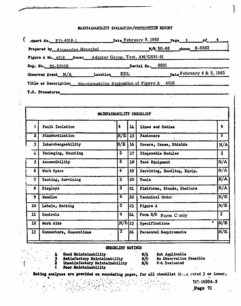
6.4 CURREN'I EVALUATION/OBSERVATION (E/O) REPORTS
The follov ng pages contain the twelve E/O Reports completedduring the period covered by this document. The reports arearranged in numerical order, by report number.
Each E/O Report consists of a M Checklist and a supplementaryrating analysis. The checklist contains numerical ratings for allmajor Maintainability features observed and evaluated during theindicated demonstration event. The supplementary rating analysisaccompanying the checklist both substantiates the numericalratings and provides constructive recommendations. The recommend-ations propose specific improvements to be made in order to attain"Good" Maintainawllity.
u nB'•ffE No" D2-14934-3*mAmE .57

XADITAI iLT EVALUATZN/= ICRT
teport No, E0D4491-3 2-6.3 2 -6 .a I of 2
p~aedb A. IR. Smith
Figure A No. 449 L omen Start Up Unit, Launch Facility OA-,966/GS 2 _62
Dvg. No. 23-33549-1 serial N.. 3
Observed Event Evaluation ,Looation. Vafb Date, 2-27-63
Title or Dessript••ý. Static Evaluation ........... ...... _
1.0. Procedures _.. .... . .......... ... .... ..
-. LMADIAUBILDLTT cOI.cLiST -
I Fault Isolation 14 Lmes and Cables
2 Standardization 15 Fasteners
3 Interchangeability F 16 Covers# Casesp Shield&
4 Packaging# Mounting 17 Disposable Modules r/O
5 Accessibility 18I Test Equipment W/A
6 Work Space K/A 19 Sevcig Handling# Eqip NIA
7 Testing, Servicing WE 20 Tools 4
8 Displays 21 Platforms• Stands# Shelters N/A
9 Handles '22 Technical Order N/E
10 Labelsp Marking 23 Figure A3 X/Ec
11 Controls 24 Form aB/C
12 Work Aids /E 25 Specifications X/V
13 Conneotorsp Connections 4 Personnel Requirement&
CHICK=u RATINGSt ' 0, o Maintainability I/A Not Applicable
• . •3 Sattisftory Maintaiablity / o N. Observation Possible2 Unsatisfactory Maintainability N ot Evaluated1Poor Maintainability
Rating analyses are provided.on succeeding pages, for all checklist items rated 3 or lower.
D2-14934-3
,Page .ue,

Report so* ki4.•."L-) Pa•ge of 2
Utem 4. a* The 3able stovage ableo-retaining lid Is flimsy and boys outvardasthin causes the three fasteners to disengage, making It impossibleto .asten the lid down.
aoomeondation.
the lid should be ribbed or flanged to stiffen it, and the fastenerss8hould be mounted one sixteenth of an inch closer to the edge of theULd.
b. The cable retaining lid does not hold itself open but must be heldup with one hand while working amongst the cables.
Decommendation.
A %gall stetion of the lid should be removed from each corner on thehinged side. This would prevent the lid from stopping against thecurved corner of the case and would allow the lid to fall back farenough to remain open.
Item 100 Three spare fuses mounted in the cable storage box are not labelled.It is necessary to remove and inspect each one to find the correctrating.
Beeemmendation.
A label identifying fuse ratings should be affixed adjacent to eachspare fuse holder.
Its* 13. The over-center fasteners holding the bottom of the start-up unit'case fall shut if an attempt is made to remove the unit in the up-'right position.
Becommendation.
The bottom lid fasteners should be turned around so that they fallopen when disengag.d, or alternatively they should be of a sprungvariety that would hold itself open.
Item 16. One connector has a loose plastic dust cap, while all others have
captive caps.
looeeomendation.
A captive dust cap should be provided for J 4 of the start-up assembly.
p.4. 4
4. I
.*... ..2" . • . D2-14934-3
I~g 4 4 *" "J.- "** a .. :

MADI'TAZX&ID1T EVALUATIOI4/ým. mom
lpert No . -392-2 .2ate Fehrumgv IQ: 1983 Page 1 .0
P•e.ared AP SALU 8dPr Rfpnmth2l N 50-66 t.hOneJL 6-6263 ..
Figure A No. 3092 Q omen Test Set, Pr grammer Grou). AN/-GSM-57
Dwgo No. 25-2825,25-29147. 25-3148. rAL No.* n0042 5-29127 ...
Observed Event, 011lifiePtainn Loation__ EDL Date February IS- 1963 _
Title or Description .unctional TTes
TO.0 Prooedures ,,./A
XM*ADIABIL.IT CHN.QIST- - -t -
I Fault isolation 3 14 LInes and Cables 4
"-2 8tandaisation 4 15 Fastener 4
3 Interchangeability 4 16 Coversp Casesp Shields 4
4 Packaging# Mounting 3 17 Disposable Modules 4
5 Accessibility 3 18 Test Equipment 3
6 Work Space 4 19 Servyicng Handling, Equip. 4
7 Testing# Servicing 3 20 Toole 4
8 Displays 4 21 Platform 3Stands, Shelters /A
9 Handles 4 22 Technical Order 3
10 Labels, Marking 3 23 Figure A 3
11 Controls 4 24 Form B/C Form C only 3
32 Work Aids 3 25 Specifications 3
13 Connector@, Connections 3 26 Personnel Requirement* 3
O3OUSTRATDNG4 Oood Maintainability N/A Not Applicable3 Satisfactory Maintainability 3/0 No Observation Possible2 Unsatisfactory Maintainability Nd Not EvaluatedI Poor Maintainability
Rating anaeses are provided on succeeding pages# for all checkliat iteu rated 3 or lower.
D2-14934-3'Pae 60

Page 2j
( _Rating Analyses for Test Set, Programmer Group, AN/GSM-57
Item I - Fault Isolation
Fault isolation to a replaceable ci.mponent is an unduly complicated task.The self-test provision of AN/GSM-57 provides a GO-NO-GO indication.If a NO-GO is indicated the Test Set must be checked by use of the AN/GJM-15 Test Center and AN/GSM-61 Test Adapter Group. This does not insurethe fault will be located since it may be in the power circuitry necessitatinguse of the AN/GSM-82(V) Test Equipment. After the fault has been corrected,a self-test will be run to determine whether or not a GO condition now exists.Therefore it is conceivable that four or more testi will run before the TestSet is returned to an operational status.
Recommendation:
Investigate the possibility of using a break-out box in conjunction withStandard Test Equipment, self-test provision of the AN/GSM- 57, and theAN/GSM-82(V) Test Equipment. This type of test setup would shorten trouble-shooting and checkout by eliminatling the need for converting from one testsituation to another.
Item 4 - Packaging, Mounting
A. The suitcases and their feet will not withstand normal organizational' -usage.
Recommendation:
Zero Modular Packaging per catalog E59 or equivalent would provide therugged test equipment suitcase needed for organizational usage.
B. The upper chassis of the Fault Locator, 25-29127-5, is mounted on thelower chassis. Mounting alignment is such that the corner hex head screwsare too close to the case (four places).
Recommendation:
Initiate an ADCN to correct the out of tolerance condition.
' D2-14934-3i , ,t . •P a g o 6 1

1item 5 - Accessibility
tj Accessibility is limited for the connection of the AN/GSM-57 to theProgrammer Group at the Launch Facility, Nine cables have to be connectedat the top rear of the Programmer Group which necessitates use of a step-ladder.
Recommendation:
Investigate packaging the Programmer Group in the type of equipment rackwhich is used at the Launch Control Facility. This type of rack would allowmore work space and would facilitate faster test setup.
Item 7 - Testing, Servicing
The test program for the AN/GSM-57 consists of punched program cards.There is no instruction on or near the card reader stating which way theProgrammer card should be inserted. Instructions are in T.O. 21-SM8OA-2-3.
Recommendation:
Provide an instruction placard or the outline of a program card on the cardreader to eliminate any dotbt as to which way the card should be placed.
.tern 10 - Labels, Marking
* A. The cable carrying case weighs 128 pounds with all cables. The eighteencable compartments are unmarked as to which cable it Is for, allowingthe technician to place each cable where he wants to.
Recommendation:
Mark the weight of the carrying case, ref. MIL-STD-803 section 10.4.3.1Mark each cable compartment for a particular cable. This will insure allcables are accounted for when the maintenance crew leaves the LF andwill maintain the weight distribution of the cables in the proper manner. SeeAttachment A.
B. Test setups could be made quicker if a placard were provided in the topcover of the Fault Locator (cable hook-up placard for Programmer Groupcheckout) and the Distribution Box (cable hook-up placard for self-test).
Recommendation:
Provide a cable- hook-up placard in the Fault Locator and the DistributionBox suitcases. See attachment B.
D2-14934-3
Page 62

Page .4
Item 12 - Work Aids
See discussion presented in items 7 and 10.
Item 13 - Connectors, Connections
The multitude of connections for self-test and fault isolation is discussedin item L Item 5 covers the accessibility aspect of making the testconnections.
Item 18 - Test Equipment
The AN/GJM-15 Test Center and AN/GSM-61 Test Adapt*Group are usedto troubleshoot the AN/GSM-57 Test Set.
Recommendation:
In'mestigate the possibility of using Standard Test Equipment and the AN/GS14-82(V) Test Equipment only. Use Standard Test Equipment for troubleshootingand maintenance whenever possible. See MIL-M-26512B (USAF).
Item 22 - Technical Order
See Attachment C.
f'tem 23 - Figure A
Figure A Technical Requirements section should have a maintainabilityand operability paragraph.
Recommendation:
Conform with instructions In AFBSD Exhibit 61-56.
Item 24 - Form B/C
Form C analysis needs revision as to personnel requirements particularly
In the callout of clock hours to complete certain tasks.
Recommendation:
Revise Form C's as more accurate time lines become available. Areas tobe Improved are test setup, test accomplishment, and return to prioro•figuration times.
( biem 25 - Specifications
Model Specification, Test Set, Programmer Group (S-133-121-3-1-10), BoeingDocument D2 - 9 140, has no reference to maintainability.
D2-14934-3Pace 63

. .... -.-.. -
Item 25 - (Continued)
Recommendation:
Conform to MIL-M-26512B (USAF) section 3.2.6.
Rern 26 - Personnel Requirements
See Item 24.
I.I
D2-14934-3
- Page 64

ATTAH j~fi.~ AZO-3092-2 Page 6
LG> Df-SNA'T CE EActA
FogR. A MiAT7~IMAP.CA15L.
ZEECT1RICAL ýCABLE CASE
W4WWW NOD2-14934-3*
PAG*E 85

ATTAC N 7% EO-3092-2 Page 7
S- ADD
/ ' ~~CAB&e: Aca.,,<- UP
FOP, PP-6AW~AIML,7 . ?OL) "7"EST
'ET SELF- TEsr
COVER IbT\6TO oQ5- 314SE (RE•.
"140fE A V No. D12-14934-8
PAG *

ATTACHMENT C P&geS
COORDINATION SHEET STO J. E. Fttzharris 2-5252 39-90 NO. MEG--34
B. R. Johnson 2-5252 39-90IMSS File 410.04
GROUP INDEX Minuteman Maintainability Engineering Group DATE FEB 114 86'3
SUBJECT " T.O.'s: 21-SM80A-2-3, 21-SM80A-8-1'iand MODEL WS-133,:33D9-111-3-1
Refe,'•nce: Coordination Sheet No. MEG-3-11, dated 1/22/63.
A Maintainability study is presently in progress on Figure A number 3092,Programmer Group Test Set, AN/GSM-57, 57A. The subject T.O.'s are being usedIn conjunction with this study. Maintennce information on the Programmer GroupTest Set can be Improved by incorporaffon of the following recommendations:
L At present T.O. 33D9-111-3-1 has no detailed instructions for performanceof Self-Test. Section 5-25 Is listed as not available.
Recommendation:
Insure that section 5-25 of T.O. 33D9-111-3-1 is consistent with sections2-54 thru 2-56 of T.O. 21-SM80A-2-3. The only difference should be the.fact that T.O. 33D9-111-3-1 will be for the SMSA and T.O. 21-SM80A-2-3will be for the LF. Incorporate the suggestions contained in CoordinationSheet MEG-3-11 in the Self-Test procedure.
.. 2. The Index of Punched Program Cards contained in each of the subjectT.O.'s is not cdnsistent•. Figure 2-2, page 2-7, of T.O. 21-SM80A-8-1differs from Figure 2-34A, page 2-74A of T.O. 21-SM80A-2-3 whichdiffers from section 1-12, page 1-4, of [.O. 33D9-111-3-L Each of thesefigures should list the same items and information.
Recommendation:
Use the same Index'of Punch Program Cards for the AN/GSM-57, 57AIn all three T.O.'s. Insure that the punched card information is accurate.
Prepared by: Approved b
A. Henschel J. S. McEacheran."Minuteman M Engineering Group
AH* . .
AncA . ..
"-D2149344-3
Page 67

XAVTAIADBILITM LALUATION)A'---%2•--•- REPCRT
Leport lNo. ".- Date 2-i-o , Page I of
Preýared b . -M/S 6 '-i phone FA 6-i76i
Figure A No. ion Noman T)., n no-t-,"ot Ao ,,1, r-.nt)
Dwg. 11o. _ _ Serial No. on•oNoo,
Observed Event None Location VAr'B Date, 2-5-63
Title or Description Static Evaluation
?.0. Procedures 21-SM8OA-2-3 Para. 2-33
HAWTAINABILITY CHECKLIST
I Fault Isolation 1 14 Lines and Cables 4
""2 Standardization 4 15 Fasteners 3
3 Interchangeability 4 16 Covers Cases# Shields3
41 Packaging, Xountirl- 2 17 Disposable Modules 4
I 5 Accessibility 4 I8 Test Equipment N/E
6 Work Space 4 19 Servicin&, Handling, Equip. N/A
7 Testing, Servicing 20 Tools 4
Displays 4 21 Platforms, Stands, Shelters N/A
"9 Handles 4 2 Technical Order 3
10 Labels, Marking 23 Figure A NA
11 Controls 24 Form B/C NA
12 Work Aids N/A 25 Specifications N/E
13 Connectors, Connections 4 26 Personnel Requirements 3
CHEKLIST RATINGS4 Good Maintainability N/A Not Applicable3 Satisfactory Maintainability N No Observation Possible2 Unsatisfactory Maintainability N Not EvaluatedI Poor Maintainability
Rating ana~yses are provided on succeeding pages# for all checklist .St•.•e rated 3 or lower.
D2-14934-3Page 68

feport No. ED-401; Page br ...
Item 1. 1• general, this test-set is of somewhat superior detailed design fromJi Yintainability viewpoint, however, according to the using group at1'%FB, it has never been mado to function. U'hether this is due to gen-crally poor reliability or to some undiscovered incompatibility is notclear as yet. It is quite certain that, in its present form, it re-presents a serious Maintainability problem since it would obviouslylead to difficulties due to its inability to perform its test function.
More specific information will be available when an opportunity occursto witness dynamic .use of the item.
Item 4. Cases 3 and 4 of the test-set are similar to each other, containing aprogram-board compartment in the bottom of the case, with a cable-
stowage space above.
It was observed that an effort has been made to provide adequate cable-stowage capabilities, but the result is not quite successful. The usualsuit-case tester problem exists, namely getting the cables into theirallotted space and getting the lid closed on them in a reasonable time.
One cable in case 3 showed a number of small but deep cuts in its insu-lation, and inspection of the lid revealed a possible explanation; thepressure-venting device protrudes inwards and may have caused the damageduring lid-closure.
The cables are stored in a special tray which is secured to the top ofthe program-board compartment by 15 slotted quick-release fasteners.The ends of some of the cables are placed in a recess at one end of thecase, down beside the program board compartment. If it is required togain access to the program-boards, it is necessary to unwind and removeall the cables, undo the 15 fasteners, and remove the cable-tray.
The connector arrestors in the center of the tray are so designed thateach cable must be stored in its proper location and in a complicatedsequence which is printed on a label on one of the arrestor lids. Thearrestor lids are hinged flaps with a quick-release fastener at theopen end; the hinges are flimsy and it seems likely that they will failin use.
Recommendation:A. The cable tray should be redesigned so that it may be removed
without disturbing the cables.b. The 15 fasteners should be replaced by a small number of fasteners
which are accassible without the need to remove the cables.c. The connector-arrestor flaps should be provided with more robust.
hinges.
Item 10. a. No weight labels were found on the cases of the test-set. Thecases are all too heavy for one man lift, but the two handles on theends of the case might invite an attempt to lift the case resultingIn probable damage to the individual or the equipment.
becommndatior.:(•Wight labels specifying two-man lift should be affixed to the
D2-14934-3"Page 69

S Reprt No. Eo-4012-2.. ,ag 3 of L
"b. "ie equipment identification label for canse 3 wan mounted insidethe viall of the cable-tray.
Recommendation:The label should be moved to the outside of the cable-tray whereit is not obscured by the cables.
a. The test cables are identified only by drawing number.
Recommendation:The cables should bear identification labels of the -type which arecommon in other test-sets. These labels show the cable desig-nation, the rec,-ptaclcs with which the connectors mate, as wellan the drawing number.
Item 15. On case number 1, the quick-release fasteners holding the equipmentchassis into the case were difficult to release. The difficulty wasdue to an outward bowing of the case along the longer sides; this bowcaused the studs to bear against the outside of the chassis holes,thereby causing the chassis to catch against the shoulders of the studs.
In order to release the chassis two men were required; one to compressthe sides of the case, the other to lift the chassis clear.
Recommendation:The shoulders of the stud should be narrower than the diameter ofthe stud shaft.
Item 16. The program-board holding fixture on the Signal Monitor, (Ca'se 2)is pro-vided with a plywood protective cover which is installed when no boardis being used. When removed from the test set this board could easilyb2 mistaken for a piece of scrap wood, and could be lost or destroyed.
Recommendation:The cover should be painted and identified.
Item 22. T.O. 21-SM8OA-2-3 paragraph 2-34a contains a note describing how tochange the keying of the adjustable plug on cable 714.
This note does not describe the process fully enough, and should beexpanded to indicate the need for disengaging the castellations onthe keying shell.
Recommendation:The note should be expanded as indicated in item 22a of
zD 1243-1/3013-1.
Item 26. All units of the test-set employ soldered connections internally. Thisprecludes repair at Field-level due to the restriction on soldering atField-level.
(4
. D2-14934-3
Page 70
XALNTAIMBI'I' rVALUATI•?.'/C......-- REPIET
.eport No. FO-4018-1 Dato February 8, 1963 Page 1 of 4
Preipred by A', l•yxadr -Henschel H/S 50-66 phone- 6-6263
Figure A No. 4A018 omen Adayter Group, Test, AN/GSM-61
Dwg. No. 25-33559 .erial No. 0001Observed Event N/A --ction EDL Date February 4 & 5, 1963
Title or Description Maintainnhi]ity Fyaluation.of Figure A 4018
?.0. Prooedures
KLWAINABILITY CHECKLIST
I Fault Isolation 4 14 Lines and Cables 4
"* 2 Standardization -7E 15 Fasteners 3
3 Interchangeability /E 16 Covers, Cases, Shields NIA
"--4 Packagingj Hounting 3 17 Disposable Modules 2
' 5 Accessibility 3 18 Teat Equipment N
6 Work Space 4 19 Servicing, Handling, Equip. NIA
7 Testing, Servicing 3 20 Tools N7A
8 Displays 3 21 Platforms, Stands, Shelters NIA
9 Handles 4 22 Technical Order N/E
10 Labels, Marking 3 23 Figure A ' N/E
11 Controls 4 24 Form B/C Form C only 3
12 Work Aids N ' 25 Specifications N/E
13 Connectors# Connections 2 "6 Personnel Requirements N/E
CHEMIIST RATINGS
. Good Maintainability N/A Not Applicable. 3 Satisfactory Maintainability N/ No Observation Possible
( 2 Unsatisfactory Maintainability N/3t. EvaluatedI Poor Maintainability
Rating analyses are provided on sucieding pagesp for all checklist it,-: rated 3 or lower.
' :,,,. ' .~ . .**..'..........""' D0-14934-3
Page 71

. 9-4018-1
Rating AnalyE.is, Figure A Number 4018
* 4.. A.) A total of eight fuses are mounted within assemblies
25-31604-1, and 25-31603-1. Four are mounted on thheat sink assembly which is part of the 25-31605-1 a.
• are mounted on the 25-33020-1 heat sink assembly %the 25-31603-1 assembly. The remaining two are lo(
S."31604-1 assembly, one is a spare. Six fuses, three aspare, are mounted on the front panel of 25-31604-1.
Recommendation:
-Place all fuses and spares (one spare per active fuspanel of their respective chassis. Provide indicatin;and positive recognition of equipment malfunction. iSection 3.1.1.
B.) Three sub-contractor manufactured assemblies haviassemblies (PCA's) which are electrically terminaticonnections. The wire route is wire harness to terrterminal board to PCA. Examination of the ReferenChassis 1193071-502, Waveform Converter Chassis ]Electrical Impedance Simulator Chassis 1193073-502
* following observations:
a.) The wire between the terminal board and PCAsufficient slack for at least three reterminatioThis condition is not met.
1b.) Form C maintenance analysis calls for unwra:"each PCA pin, replace the faulty PCA, and wr,the PCA. This method decreases the reliabiliconnection because of the wire having had an c
c.) Maintenance technicians may forget the PCA's-and pull without first removing the wiring. Th
S. 3 , *. . require replacement of PCA, terminal board,' . ' .. .. -.. . . 3•; . ° . :;. . . ,., . i . 3,• .: • ' ". .- : ,".
• • '" •',•': "'- t ~ .3 3o , ... 3 '' '- ., ' " ' , ' "
,,. • .S" , , .. . , .• . . . . .3. . ' ,
*"".. " ", ',"" ' 4. "" "" 3 .d . " 3

: d.) 'When the AN/GSM-61 and AN/GJM-15 are being used to checkassemblies for faults, unnecessary downtime will result if thefault is traced to a wire wrapped PCA. This will be the repairand checkout time difference between a fault traced to an assembly
* containing wire wrapped PCA's and one to an assembly containing, " modules which are plug-in.
Recommendation:
-'Alternative L
. Investigate feasibility of re-design to eliminate the (se of wireS" wrap terminations. Provide etched circuit boards antmodules" " with the plug connector in accordance with Boeing Standard
I ... C45BN-3A or equivalent , and the receptacle in accordance withBoeing Standard C45BN-1 or equivalent. See STL Document
" 6120-6882-DU-RDL
* Alternative IL
'a.) Revise Form C analysis to call out the following remove and replace* .techniques for wire wrapped PCA's:
Remove: L) Cut each wire as close as possible to the PCA pin.S. . -Tag as necessary for identification.
.2..) Remove PCA mounting hardware.
*.3.) Remove PCA.
4.) Strip each wire in preparation for wrapping tonew PCA. If sufficient length is not available re-
. .place wire between terminal board and PCA.
Install: L) Install new PCA.
2.) Install PCA mounting hardware.
3.) Use a wire wrapping tool to connect wiring to PCA.
'4.) Route repaired assembly through test center.
"b.) Provide a warning placard within assemblies containing wirewrapped PCA's stating the PCA's are not plug-in type.• ( " , "V:. .;o • i , : " ' . " .. i, : " " ' " " " " "I ' t
. , . D2-14934-3Page 73

0O-401
5. Access panels at the rear of the cabinet are fastei
Recommendation:
Provide hinged access panels. See MIL-STD-803
7. See items 4 and 5.
8. See item 4.
10. Certain removable assemblies weighing over 45 pwith their unit weight. An example is the Progra_28170-1.
Recommendation:
Identify unit weight for assemblies weighing overSTD-803 section 10.4.3.1
13. Solder connections are used through out the unit.
Recommendation:
Use plug-in assemblies, crimp-on connectors, or.on "pig-tail" lead wires to a plug-in or mechanic"Document 6120-7822-DU-RDI, Maintainability Cril
15. See item 5. "
17. See Item 4.B
24. See item 4.B 1
'I ..
* . S,, , . . . • , . , . .

MAINTA ;AILr EWLUAT A="t'* BEPMT
.aport No,. ro-4o8-2 Date 2-14-63 .. .Page I s 3
Prepared by _A.j S. Ith 6207-1 phone, 6-.?1
Fizpro. A No. 4018 Nomsn Tpst PA"ter Group (Proramner)
Dwg. No. 25-28170-1 _Serial No. 0000002
Obsevor;X Event ,Evaluation Locationk VAFB Date 2-11-63
Title or Description z rrineorinr evaluation of stepninF --:itches.
?.0. Procedures_. .... ... ....
MAITAINABILITY CHECKLIST
I Fault Isolation N/O 14 Lines and Cables N/Z"I " 2 9 S t a nda rd i zat i o n 4 i1 F a st e n er s N I S
3 Interchangeabilty 4 16 Covers, Cases# Shields4
4 ackagingj, 'utn2 17 DsoalXdla4
5 Accessibility 3 18 Test Equipment N1
6 Work Sace N/A 19 Serviin, Handling, Equip. 37 TestinZ, Servicin- N1O 20 Toole Shltr
a Displays NIA 21 Pltforms Stands# Shelter& NIA
SHanle 22 Technical Order N/B
10 Labels1, rking 3 23 Figure A X/E
11 Controls 4 24 Form B/C N/E
12 Work Aide N/E 25 Specifications NI/
13 Connectors, Connections 3 26 Personnel Requirements 2
CHECKLIST RATINGS4 Good Maintainability N/A Not Applicable3 Satisfactory Maintainability Nb No Observation Possible2 Un•tsfactory Xaintainability N Not EvaluatedI Poor Mintainability
Rati•n anayseeo are provided on succeeding pagese for all checklist itsms rated 3 or lower,
D2-14934-3
Vamp 75

Deport No. L; Y'S-• Page 2 of0
Item 4. The evaluation observed was concerned primarily with the steppingswitches in the Program..,ur drawer. Other areas were not accessiblefor evaluationl this report will therefore be more concerned withthe programmer than any other component of the Fig A 4018.
a. In general, the Programmer is a very solidly constructed itemand gives a strong impression of over-engineering. Its weight(in excess of 200 pounds) appears to derive very largely from achassis constructed of )* inch alloy, and from thick bundles ofwires which are broken frequently by terminal boards.
Recommendation
A review of the packaging of the programmer is highly desirable, todetermine the feasibility of reducing the weight of the unit and thecomplexity of the wiring. Special attention should be given to thepossibility of dividing this unit into two or more units of moreconventional size.
b. A row of throe stepping-switches is mounted across the middleof the upper chassis. The switches are sealed units, approximately6 inches by 4 inches on the base, and they are mounted by means ofhex-headed studs over holes in the chassis so that the comnnectorsprotrude through. There are seven quick-release Bendix connectorson the base of each switch. One of the studs is used to mount adiode-board, the components being placed on the "inside", that is,over the head of the bolt. This arrangement causes great difficultyin removing the stepping switch, since space is very cramped under-neath the chassis. Tho problem is aggravated by the presence oftwo stacks of terminal strips on the side of the unit which impedefree access to the stepping-switch bases. The basically simpletask of removing two components took two hours to accomplish.
Recommendation
1. The mounting studs of the stepping-switches should be accessiblefrom above the chassis, i.e., the switches should be screwed downonto the plate instead of being secured from below.
2. An alteraativo mounting point should be provided for the diode-boards, and again this should be removable from above.
3. The leads to the stepping-switch should be more readily removedthan at present (see item 13). This might include providing longerleads to allow the switch to be partly withdrawn allowing access to t
the connectors on the underside.
Item 5. In order to remove the middle one of the three topmost stepping-.. switches, it would apparently be necessary to remove all the connectors
from the base of one of the outer switches. The task bristles withdifficulties due to the extremely poor accessibility of the sevenBendix plugs on the base of each switch. These plugs are so closelypaaked that it is only possible to grip them with the fingers and"nudge" them around, a process which is painful, tiring, and time-
D2-14934-$Doce 78

Report No* EO-'4'ýl5-2 Pase 3 of 3
"This difficu:. would remain even if the reoomaendations of item( were adopted to improve the ease of removal.
Recommendation
The method of making electrical eonnections to the stepping-switches ahould be changed. Ideally these components should beplug-in units.
Item 10 The Programmer weighs in excess of 200 pounds which requires the useof a fork-lift for handling. The unit is not labeled to this effect.
Recommendation
A weight label calling for the use of a mechanical hoist should beaffixed.
Item 13 The problem of crowding of connectors on the stepping-switches wouldbe disposed of by the recommendation of item 5.
It was noted that there is an enthusiastic employment of terminalstrips throughout the unit. These strips impede access and increasecost and complexity, without apparently serving any other function.A bundle of wires will be broken by a terminal strip, with the greatmajority of the wires going straight on through to be regrouped intoa bundle again.
Recommendation
The existing system of wirin: should be replaced by a "harness" systemto avoid redundant break-pcints. This process would undoubtedly beeased by repackaging the unit into two drawers.
Item 19 It was necessary to employ a hydraulic 'LO-LIFT" to handle the pro-grammer in the Vandenberg SMSB, and the process entailed the use ofsix sen. If the weight of the unit cannot be reduced, or if the unitcannot be divided into two chassis, then a suitable handling fixturewill be required.
Recommendation
It must be verified that a suitable mechanical hoist will be availablefor handling this item.
Item 26 The apparently simple task of removing two stepping-switches from theProgrammer required the expenditure of 12 man hours. Part of theeffort required the presence of six mon to aid in handling.
With proper redesign of this unit it is estimated that the time couldbe reduced to one man hour or less.
C
D2-14934-3
Page 77
#J

MDINTAINABILI T~tt~~rM/OBSUVATION REPORT
sport go._ . W-4018-, _ .ate 2-27-63 Pa. o 1 s
ipared bz A. .Sith. )/ 7-p ono. 866-3761 "
Figure A No.o ,it Nomenr Test Adapter Group
Dwg. No,-. 2-M876-1 J eorial No. ,
Observed 1vent _ OL. V&V _XLo&tio, VAYB Date 2-25-63
"Title or Deboriptio. Operational Checkout
T.O, Proooduro 33D7!-50-3-1 Pra. 5-5 thru 5-f .3
KIMNTAINABILIT OCH IST
I Fault Isolation 14 Lines and Cableso
2 Standardization 15 Fasteners
3 Interchangeability 16 Covorp Caoesp Sh•elds
, Packaging, Mounting 17 Disposable Modules
5 Accessibility . 18 Test Equipment N10
NO6 Work Space 19 Servioing, Handling# Equip.
Testingj, Servicing 4 20 Tools
8 Displays 4 21 Platforms# Stands, Shelter* NIS
9 Handles 22 Technical Order
10 Labels, Marking 2 23 Figure A
1 Controls .24 Fom B/C . ..
12 Work Aids 2- Specifications
23 Connectors, Connections 4 Personnel Requirements N/.
CHECKLST RATINGS4 ood Maintainability \ N/A Not Applicable3 Satisfactory Maintainability 3/ No Observation Possible
4 2 Unsatisfactory Maintainability. Not Evaluatedt POWr Maintainability
Ratifganyoses are provvied on succeeding pages, for all checklist items rated 3 or lower*• i 41
• .,.: *.D2-14934-4
once 78

-. • • m, ,-~..• • -. -r
Report No. i-.o18-, Page 2 of 3
item 4. Circuit Control Boards have a pair of hooked projections on themating surf&ac which engage a retaining device when the Release Handleis raised*
It has been observed at VAIn that it is very easy for an inexperiencedoperator to damage the unit during board-insertion; if the bottom ofthe board is not firmly pressed inwards until it clicks, the retainingpin fouls the ends of the hooks and the great mechanical advantage ofthe release handles enables the operator to snap the hooks off with-out feeling any resistance*
ieoommetdation.
a. The retaining hooks should be bevelled to reduce the flat end-area,and to allow the retaining pin less chance of fouling.
b. The hooks should be strengthened.
o. A cautionary note should be Inolu4ed in all T.O.'s dealing withCircuit Control Board removal and replacement, especially331D7-50-3-1. See item 22.
do A cautionary label should be affixed to the cover of each boardstressing the need to press the board home firmly before raisingthe handles.
Item 10. The Fig. A 4018 nameplate in mounted on the left hand end of theunit, and is Invisible when the unit is used adjacent to dthirequipment.
Reoommondation.
'hg nameplate should be mounted on a forward-faoing surface.
Item 13. No protective cover in provided for the front of the ProgrammerDrawer when a Circuit Control Joard is not installedo At VAYDIt is the practice to tape a piece of cardboard in place.
* oecommendation.
A simple plastic dust-cover shouild be provided for the front ofthe Programmer Drawer.
Item 22. .o paragraph 5-7i Is somewhat confusing. During Operational Check-out four test sequences are runt each one with a separate circuit
- eOtrol board. This paragraph implies that it is not necessaryto tan power off before changing control boards.
. DUring the VTV observed the Test Operator directed the Air Forceteobmicia to put the A624 into MODE 1 at the end of stop 11 thisproedure removes power from the 4018 and makes it safe to change
( seemamiatic.-• ;.. • lboarmda* d
t.o.o 307jO.5.34 p gramph step I should be revised to show
*r D2-14934-3"Va"e '•9

96-4018-1 Page 2
Rating AnalyE.is, Figure A Number 4018
4.A.) A total of eight fuses are mounted within assemblies 25-31605-1,
25-31604-1, and 25-31603-1. Four are mounted on the 25-32950-4* heat sink assembly which is part of the 25-31605-1 assembly. Two
are mounted on the 25-33020-1 heat sink assembly which is part ofthe 25-31603-1 assembly. The remaining two are located in the 25-31604-1 assembly, one is a spare. Six fuses, three active and three
, spare, are mounted on the front panel of 25-31604-1.
Recommendation:
-Place all fuses and spares (one spare per active fuse) on the frontpanel of their respective chassis. Provide indicating fuses for rapid-and positive recognition o~f equipment malfunction. See MIL-M-26512BSection 3.1.1.
B.) Three sub-contractor manufactured assemblies have printed circuitassemblies (PCA's) which are electrically terminated by wire wrappedconnections. The wire route is wire harness to terminal board, then
* terminal board to PCA. Examination of the Relerence Signal GeneratorChassis 1193071-502, Waveform Converter Chassis 1193072-502, andElectrical Impedance Simulator Chassis 1193073-502 results in thefollowing observations:
a.) The wire between the terminal board and PCA should havesufficient slack for at least three reterminat ions at the PCA end.
.* This condition is not met.
b.) Form C maintenance analysis calls for unwrapping the wire ateach PCA pin, replace the faulty PCA, and wrap each wire tothe PCA. This method decreases the reliability of the electricalconnection because of the wire having had an extra wrap cycle.i
c.) Maintenance technicians may forget the PCA's are wire wrapped,-,%and pull without first removing the wiring. The results will
.. require replacement of PCA, terminal board, and wiring.
. , . .. .. . **... * ,, ' V. I'. , ' , * ., ,. , ,4 .
." -. " • D2-14934-3
.. Page '72

; 0401 8-1
d.) When the AN/GSM-61 and AN/GJM-15 are being used to check. ,assemblies for faults, unnecessary downtime will result if the
fault is traced to a wire wrapped PCA. This will be the repairand checkout time difference between a fault traced to an assemblycontaining wire wrapped PCA's and one to an assemblycontainingmodules which are plug-in.
Recommendation:
-'Alternative L
. "7 •Investigate feasibility of re-design to eliminate the itse of wirewrap terminations. Provide etched circuit boards andmodules"with the plug connector in accordance with Boeing StandardC45BN-3A or equivalent , and the receptacle in accordance withBoeing Standard C45BN-1 or equivalent. See STL Document
:6120- 6882-DU-RDL
Alternative IL
' .• ) Revise Form C analysis to call out the following remove and replacetechniques for wire wrapped PCA's:
Remove: L) Cut each wire as close as possible to the PCA pin..,.,,.Tag as necessary for identification.
.2.) Remove PCA mounting hardware.
3.) Remove PCA.
.4.) Strip each wire in preparation for wrapping tonew PCA. If sufficient length is not available re-place wire between terminal board and PCA.
Install: L) Install new PCA.
* 2.) Install PCA mounting hardware.
".-. :3.) Use a wire wrapping tool to connect wiring to PCA.
"4.) Route repaired assembly through test center.
*:-b) Provide a warning placard within 'assemblies containing wire- wrapped PCA's stating the PCA's are not plug-in type.
• ., S. * .*r ... .
*• *.' , , , ' " , .. . . . S. *',. . . . ,,, ,. ; ' , ." - ,. .' . ." ,,.' .
C D2-14934-3Page 73

10-4018-1 Page 4
5. Access panels at the rear of the cabinet are fastened by Phillips screws.
Recommendation:
Provide hinged access panels. See MIL-STD-803 section 10.4.3.5.5.* 1" ~rfl
7. See Items 4and 5.
*8.See item 4.
10. Certain removable assemblies weighing over 45 pounds areinot markedwith their unit weight. An example is the Programmer Assembly 25-
*28170-1.
Recommendation:
Identify unit weight for assemblies weighing over 45 p~ounds. See MEL-SMD-803 section 10.4.3.1
13." Solder connections are used through out the unit.
Recommendation:
Use plug- in assemblies,, crimp-on connectors, or. components with soldered-on "pig-tail" lead wires to a plug-in or mechanical connectors. See STLDocument 6120-78R22-DU-RDI, Maintainability Criteria, dated- 16 March 1962.
*15. See item 5.. .
* 17. See Item 4.B **I
24. See item 4.B
D2-14934-3
Page 74

MA~yrAKAAILIT EVALUATI0NA=.0:%- RUPMT
(sport go, oo-4oi8-2 Dat. 2-14-63 .Page I o 3
Prepared by A. ::. 5-ith .62o-1 .phone 6•-3761 _
Fiure.A No. 4018 No1oexn Test P-1A-ter Group (Propraier)
Dvg. No. 25-28170-1 Serial No. 0000002
Observc4 Event Evaluation LoO&tioq VAFB Date 2-11-63
Title or Description !SEhneering evaluation of stepping sn.itche.s.
?.O. Proedureae
NA1AT ABMILMX CHECKLIST
I Fault Isolation N/O 14 Lines and Cables N/I
"" 2 Standardization 4 15 Fasteners N/I
Interchangeability 4 16 Covers# Cases$ Shields 4
4 Packaginz., -uanj 2 17 Disposable Hoduice 4
5 Accessibility 18 Test Equipment N10
6 Work Spaoe N/A 19 Servicing, Handling,, Equip. 3
, 7 Testing, Se-ioin; N/O 20 Tools N10
a Displays N/A 21 Platforms# Stands, Shelters N/A
9 Hanles 4 22 Technical Order N/I
10 Labels, Marking 23 Figure A ,
1 Controls 4 2 Yorm B/C X/E
12 Work Aids N/E 25 Specification3 aIZ
13 Connectors, Connections 3 26 Personnel Requirements 2
CHECKLIST RATDIG
4 Good Maintainability N/A Not Applicable3 Satisfactory Maintainability N/O No Observation Possible2 Unsatisfactory Maintainability / Not EvaluatedI Poor MaIntainability
lating analyses are provided on succeeding pages, for all checklist itsms rated 3 or lower,
D2-14934-3
Doer^ 75

Report No. L.; ',.-Ž Page 2 of 3
Item 4,. The evaluation observed was concerned primarily with the steppingswitches in the Progra=;.or drawer. Other areas were not accessiblefor evaluationj this report will therefore be more concerned withthe programmer than any other component of the Fig A 4018.
at In general, the Programmer is a very solidly constructed itemand gives a strong impression of over-engineering. Its weight(in excess of 200 pounds) appears to derive very largely from achassis constructed of ) inch alloy, and from thick bundles ofwires which are broken frequently by terminal boards.
Recommendation
A review of the packaging of the programmer is highly desirable, todetex-rne the feasibility of reducing the weight of the unit and thecomplexity of the wiring. Special attention should be given to thepossibility of dividing this unit into two or more units of moreconventional size.
b. A row of throe stepping-switches is mounted across the middleof the upper chassis. The switches are sealed units, approximately6 inches by 4 inches on the base, and they are mounted by means ofhex-headed studs over holes in the chassis so that the connectorsprotrude through. There are seven quick-release Bendix connectorson the base of each switch. One of the studs is used to mount adiode-board, the components being placed on the "inside", that is,over the head of the bolt. This arrangement causes great difficultyin removing the stepping switch, since space is very cramped under-neath the chassis. Thi problem is aggravated by the presence oftwo stacks of terminal strips on the side of the unit which impedefree access to the stepping-switch bases. The basically simpletask of removing two components took two hours to accomplish.
Recommendation -
1. The mounting studs of the stepping-switches should be accessiblefrom above the chassis, i.e., the switches should be screwed downonto the plate instead of being secured from below.
2. An altera.ative mounting point should be provided for the diode-boards, and again this should be removable from above.
3. The leads to the stepping-switch should be more readily removedthan at present (see item 13). This might include providing longerleads to allow the switch to be partly withdrawn allowing access to tthe connectors on the underside.
Item 5. In order to remove the middle one of the three topmost stepping-switches, it would apparently be necessary to remove all the connectorsfrom the base of one of the outer switches. The task bristles with"difficulties due to the extremely poor accessibility of the seven
eandix plugs on the base of each switch. These plugs are so closelypacked that it is only possible to grip them with the fingers and"nudge" then around, a process which is painful, tiring, and time-
0~o
D2-14934-3oDmwe 76

Report No. JO-:18-2 Page 3 ot 3
"This difficul.,y would remain even if the recommendations of item 4( were adopted to improve the ease of removal.
Recommendation
The method of making electrical connections to the stepping-switches should be changed. Ideally these components should beplug-in units.
Item 10 The Programmer weighs in excess of 200 pounds which requires the useof a fork-lift for handling. The unit is not labeled to this effect.
Recommendation
A weight label calling for the use of a mechanical hoist should beaffixed.
Item 13 The problem of crowding of connectors on the stepping-switches wouldbe disposed of by the recommendation of item 5.
It was noted that there is an enthusiastic employment of terminalstrips throughout the unit. These strips impede access and increasecost and complexity, without apparently serving any other function.A bundle of wires will be broken by a terminal strip, with the greatmajority of the wires going straight on through to be regrouped intoa bundle again.
Recommendation
The existing system of wirin;; should be replaced by a "harness" systemto avoid redundant break-points. This process would undoubtedly beeased by repackaging the unit into two drawers.
Item 19 It was necessary to employ a hydraulic '"L-LIFT" to handle the pro-grammer in the Vandenberg SMSB, and the process entailed the use ofsix men. If the weight of the unit cannot be reduced, or if the unitcannot be divided into two chassis, then a suitable handling fixturewill be required.
Recommendation
It must be verified that a suitable mechanical hoist will be availablefor handling this item.
Item 26 The apparently simple task of removing two stepping-switches from theProgrammer required the expenditure of 12 man hours. Part of theeffort required the presence of six men to aid in handling.
With proper redesign of this unit it is estimated that the time couldbe reduced to one -an hour or less.
D2-14934-3
Page 77

.!
NWAITAINADILTT •]•L•/O9 OSUT AT•ION BZPQi~T
sp o r t so . . . ! -4 o 1 8 -3 .D a t o . 2 -2 7 -6 3• .•_o -,- 7
Poejared b, A. I. Smith• 1/ 6207-1 on. 86663761 I71gw! L No., om@n Test Adapter Group _
Dwg. No. - 5-26876-1 seria No. 5
Obseved ~nt_ Ln .... nio VA B Date 2-2563
Title or Desoripti*" en - Operational Checkout
T.O. Prooodures -50-3-1 Para. 3-5 thru 5-11
WIANTAITABILIT! CHEC•IKST
I Fault Isolation 14 Lines and Cables
2 3tandardisation 15 Fasteners
3 Interchangeability 16 Covere, Caseso Shields
4 Packagingj, Mounting 3 17 Disposable Modules
5 Accessibility 4 18 T est Equ ip ment -/0
6 Work Space 19 Servicing, Handling, Equip.
7 Tooting# Servicing 20 Tools8 Displays 4 21 Platforms, St•a•n, Shelters N/E
9 Hisles 4 22 Technical Order
10 Labolo, Marking 2 23 Figure A
1 Controls 24 Form B/C
12 Work Aids 25 Specifications
13 Connectors, Connection.- - Personnel Requirements
., .- .-
CHECCLIST RATINGS4 @0od Maintainability N 1/A Not Applicable3 Satisfactory ntainability N/O No Observation Possible
( ~2 Unsatisfactory Maintainability. N not EvaluatedI lotManaiailt
tatin an47y0ee o e providedLon suceeding pages, for all choeklist i•sma rated 3 or lower*
.D2-14934-4.
Dug@ 7

Deport No. 10-4018-- Pago 2 of 3
Item 4. Circuit Control Boards have a pair of hooked projections on themating surface which engage a retaining device when the Release Handleis rasiedo
It has been observed at VAFB that it is very easy for an inexperiencedoperator to damage the unit during board-insertion; if the bottom ofthe board is not firmly pressed inwards until it clicks, the retainingpin fouls the ends of the hooks and the great mechanical advantage ofthe release handles enables the operator to snap the hooks off with-out feeling any resistance.
Recommendation.,
a. The retaining hooks should be bevelled to reduce the flat end-area,and to allow the retaining pin less chance of fouling.
b. The hooks should be strengthened.
e. A cautionary note should be included in all T.O. 's dealing withCircuit Control Board removal and replacement, especially33D7-50-3-1. See item 22.
d. A cautionary label should be affixed to the cover of each boardstressing the need to press the board home firmly before raisingthe handles.
Item 10. The rig. A 4018 nameplate is mounted on the left hand end of theunit, and is invisible when the unit is used adjacent to dthkr 1equipment.
Reoommendation.
The nameplate should be mounted on a forward-facing surface.
Item 15, No protective cover is provided for the front of the ProgrammerDrawer when a Circuit Control Board is not installed. At VAFBit is the practice to tape a piece of cardboard in place.
* Reeomondation,
A simple plastic dust-cover should Je provided for the front ofthe programmer Drawer.
'Item 22. a* Paragraph 5-71 is somewhat confusing. During Operational Check-,out four test sequences are run, each one with a separate circuit
- eeatrol board. This paragraph implies that it is not necessaryto turn power off before changing control boards.
V=u* the V&V observed the Test Operator directed the Air ForceteeUsmile to put the A624 into NODE I at the end of step I; thisproeedere remove. power from the 4018 and makes it safe to change
V.0 "33', -3•43 paragraph 5-? step L should be revised to show
D -14934-3"Page '79

Report No, W-O1C-3 Pap 3 of 3
( "the necessity for removing power from the Fig. A 4018 beforechanging Circuit Control Boards.
be T.O. 33D7-50-3-1 paragraph 5-4 describes the process of installingand removing C'rouit Control Boards. The procedure does not stressthe importance of snapping the bottom of the board firmly home beforeraising the handles. See item 4,
Recommendation.
A cautionary note should be added to paragraph 5-4, or step d shouldbe rewritten to stress the importance of proper location of theboard*
1 - -•
V°
* C
* .' S S
" ,* *2-14934-
- Page 80

KaDTAImAbxL1TT Am U/ObSnVATIOu REumT
port No, Eo,.152-1 - Date 2-21-63 ,page I o. .
Prepared, by A. * . Smith6 -1 hos 67
Figure A No. 4152 Nomen Electrical Test and Maintenance Table FN-136/GSM-82 (v)
Dwg. No.. 25-34145-1 Serial No. 0000001
Obse -wed Event V&V Location VAFB Date 2-18-63
Title or Descriptica- T.O. V&V
T.O. Procedures 3IX3-12-8-2 Paragravh 11.
ANTAIBIL2ZTT CHECKLIST
! Fault Isolation N10 14 Lines and Cables- A
21 Standardization 4 15 Fasteners 33 Interchangeability 4 16 Covers, Cases, Shields 4
4 Packaging, Mounting 1 17 Disposable Modules N/O
"5s Accessibility 4 18 Test Equipment 4
* 6 Work Space b 19 Servicing, Handling# Equip.
7 Testing, Servicing 3 20 Tools T.8 Displays 3 21 Platforms, Stands, Shelters NIA
9 Handles 4 2 Technical Order 3
10 Labels, Marking 3 23 Figure A N/E
21 Controls 24 Form B/C N/•
12 Work Aids h 25 Specifications N/I
23 Connectore, Connections 6 Personnel Requirements
CHECLIST RATINGSSGood Maintainability N/A Not Applicable
3 Satisfactory Maintainability x/ No Observation PossibleS2 Unsatisfactory Maintainability x Not Evaluated
I Poor MaintainabilityWiatng analyses are provided on succeeding pages, for all checklist ite-iG rated 3 or lower.
D2.14934:3Paoe 81 81 'j

aeport m-4l•:: .] Page 2 of 4
Item 4. a. To date one Adapter Connector and 3 Dummy Loads have been found( to have connectors transposed. They are: HX-4284 Adapter
Connector Dummy Decoder;Dummy Loads, Electrical DA-304, DA-305,DA-306. This is not strictly a maintainability problem, butthe situation must obviously be rectified if these items are tobe used.
b. The Fixture, Cooling Air, Part No. 25-35685-1 is designed topermit rotation of the drawer under test to gain access to theunderside. The cooling air is supplied through a rotating joint,no doubt quite a costly feature, presumably to allow rotationwhile power is applied. The design of the trolley however is suchas to prevent rotation of the drawer when it has an adapter andcables attached. It is necessary to remove all cables, and theadapter in order to rotate the drawer.
Recommendation.
The "table-top" structure of the trolley should be eliminated,since it is quite useless in its present form. It is too narrowto serve as a work surface. The rotating joint of the drawerfixture should be supported by simple vertical posts risingdirectly from the base structure. This would permit free accessto the fixture and wouId permit rotation without dismantling ofthe test set-up. The cost of the fixture would also be consid-erably reduced by elimination of the decorative plastic and woodelements of the present fixture, together with elimination of theremarkably complex and expensive swivelled stainless steel handle.
Item 5. When a drawer is mounted in the Fixture, Cooling Air, it is notpossible to remove the dust covers from the drawers without dis-torting them, because the openings top and bottom are a fractionof an inch too small.
Recommendation.
The size of the access holes should be increased to allow instal-lation and removal of dust covers while a drawer is in the fixture.
Item 7. AVTRON T242B LOAD-BANK ELECTRICAL is adjusted by using a Multi-meter and test leads (see paragraph ll-19d of T.O. 31X3-12-8-2)but the terminals of the load bank have no provision for insertingtest leads. This requires the operator to press the leads againstthe terminals manually while adjusting the load bank with his thirdhand. This procedure could also result in error due to poor elec-trical contact.
Recommendation.
a S oles should be drilled in ends of the terminals to aeoomodatebanana Jacks.
4. b. Provision should be made for measuring the resistance at a properJack on the panel of the Teat-Set, Voltage Regulators, ProgrammerOroup TB-i7/SK,)
D2-14934-3Page 82

Report No.. IO-i1*52-l Page 3eof 4 _
Item 8. Paragraph ll-21g calls for the use of the OHMS XI.oale tomeasure 30 ohm resistance of the load bank.
Recommendation.
The OHMS X10 scale will give a more accurate reading in this case.The T.O. should be changed to this effect.
Item 10. a. During Voltage Regulator checkout, W-18 is connected to the LoadBank Electrical. The terminating lugs of W-18 are indistinctlymarked as El and E2 by means of a molded impression. T.O. 31X3-12-8-2, Figure 11-1, refers to these terminations as P2 and P3.
Recommendation.
A yellow adhesive label identifying the terminals as E1 and E2shoult be affixed, and the T.O. Figure 11-1 should be changedto agree with the hardware.
b. The AVTRON T-242B Load Bank has no veight label although it weighsaround ?0 pounds.
Recommendation.
A weight label .should be affixed.
Item 13. a. W-16 is connected to the Airflov Interlock connector on the Fixture,Cooling Air during drawer testing.
The cable terminates in a connector which is approximately 7 inchesin length while being only " in diameter at the point of entryinto the socket. Almost any accidental blow will break thisconnector or the socket.
This problem is fairly common throughout much of the equipmentemploying Pyle National connectors, but is especially hazardousin the thinner ones. It seems amazing that a seven inch "lay-back" is required to connect three conductors.
Recommendation.
An attempt should be made to provide a more practical connectorin this application. Preferably an investigation of wider scopeshould be initiated to determine whether Pyle National connectorsshould be used at all on test equipment, on account of theirexessive bulk and use of multiple-turn connections.
In some applications, the use of strap wrenches and torque-wrenchkits Is being advocated for" these connectors, which seems absurdwhen it is recalled that these applications are for static ground-based test equipment.
It seems almost certain that a better connector should be availableat or below the price of these items, which would incorporate the
,desirable features of quick oonnect/disconnect, and ruggedness.
D2-14934-3Page 83

Report V). J,- .4152-1 Page 1, of 4
Item 13. b. w-i8 of the test set-up is terminated by flat circular terminal-.lugs. In order to connect these terminals it in necessary to
remove the retaining knobs on the T242B Load Bank; it in thendiscovered that it is not possible to screw the terminals downtightly because the lugs are not long enough to clear the shouldersof the knobs.
Recommendation.
The terminal lugs on W-18 should be longer and more robust andshould be of the open-sided variety.
Item 15. The fasteners used to lock an Adapter on the back of a drawer tendto swing 2ut when the drawer (minus adapter) is rotated and catchon the "Eible-top" surface of the Cooling Air Fixture. In onecase the fastener broke off.
Recommendation.
If the recommendation of item 4b is not accepted, these fastenersshould be replaced by a spring variety that will remain close tothe side of the drawer fixture when disengaged.
Item 19. Deficiencies in the Fixture, Cooling Air have been dealt with underitem •.
Item 22. a. T.O. 31X3-12-8-2, Figure 11-1, refers to the terminals of W-18 asP2 and P3. (See item 10.)
Recommendation.
The T.O. should be revised, identifying the terminals as El and E2to agree with the hardware. Flagnote 1 should be similarly revised.
b. See item 8.
D2-14934-3
Page 84

MAINTAINAILITY EVALUATION/OM%%qeA*-FVCRT
Aport go. m-44o-1 Date 2-11-63 Page.I
Preparod. A. ... Smi th phone._ .6• !
Figure A No. 44Q Nomen Simulator oet. Electrical Functions, Missile-Launch AN/GSH-62
Dwg. NO. 25-33q4o-1 Serial No. Set #2
Observed Zvent None Lo~ction. , FB Date 2-11-63
Title. or Description Static evaleation F.
I.*. Procedures 3319-14-26-1 (Oberation and Maintenance)
MLDNAIKABILITY CHECMIST
I Fault Isolation 14 Lines and Cables
-2 Standardization 4 15 Fasteners3
3 Interchangeability 4 16 Covers# Cases# Shields
it Packaging, Mounting 3 17 Disposable Modules I/O
5 Accessibility 4 18 Test Equipment IN/O
6 Work Space • 19 Servicing, Handling, Equip. N/A
7 Testingj, Servicing N/O 20 Tools N10
8 Displays 1 32 Platformsp Stands# Shelter. N/A
9 Handles 4 22 Technical Order N/IE
10 Labels, Marking 3 23 Figure A N/I
11 Controls 24 Form B/C /Z
12 Work Aids N/O 25 Specifications ' /Z
23 Connectors# Connections 4 26 Personnel Requirement* /s
CHECKLIST RATINGS
4 0ood Maintainability NA/ Not Applicable3 Satisfactory Maintainability / Mo Observation Possible
( 2 Unsatisfactory Maintainability N Not EvaluatedI Poor Maintainability
Rating analses are provided on succeedipS pages, for all checklist items rated 3 or lower.
D2-14934-3

Report No, 490-. * 2 of3
Item 4 The two Emall Junction-boxes stored in the Distribution Box are heldin place by a plate which is secured by eight slotted quick-releasefasteners. It is necessary to remove the dust-caps from two of thesockets in order to remove the retaining plate, because the hole inthe plAte is too small to pass the skirt umbilical dust cover, and thedust cap on the small connector is attached to the plate by a chain*
Recommendation.
1. The retaining cover should be hinged along one aide and fasteneddown with no more than. two butterfly type quick-release fasteners.
2. The holes should be enlarged to alloy the retaining plate to beremoved .without removing dust caps.
Item 8 The Signal Data Recorder has an indicator lamp adjacent To the ON-OFFswitch. The word POWER is printed beside this indicator, implying thatit will be illuminated when the recorder is switched on. During theevaluation the recorder was hooked up but not switched on, but it wasobserved that the lamp was glowing dimly. This situation was somewhatconfusing because if the lamp is supposed to indicate that power isavailable, then it should be identified accordingly as POWER AVAILABLE,and the lamp should be bright enough to be easily discernible. If thelamp indicates that the recorder is switched on, then it should notglow at all when the unit is switched off. There is no circuit diagramin the Operation and Maintenance T.O., nor is there any descriptivematerial that indicates the proper mode of operation of this indicator.
Recommendation.
The function of the indicator should be clarified by an unambiguous label,and the T.O. should describe the Signal Data Recorder more fully.
Item 10 a. It was observed that temporary adhesive labels had been affixed toeach box of the test-set showing "Fig A 4490" and "CASE 1 of 6" etc.
This practice of identifying Items by temporary Fig A number labels hasbeen adopted extensively at Vandenberg due to the confusion arising outof the use of several different identification systems. For example oneitem may be known by ACO number, drawing number, Federal Stock Number,BGS number or Figure A number.
Recommendation.
All Figure A items should be prominently labeled to aid in recognition.
b. The Individual cases of the Fig A 4490 observed were all identified"as being serial number 2, but the over-all Test-Set number as shown onthe label of the Simulator was serial number 4.
"It Is quite possible that this situation is the result of an error, butIt does indicate the desirability of listing component parts and serial
( aumbem an a master label.
. ' D2-14934-3Page 86

Ieport No. ID-4490-1 Pag 3 eot 3
Recommendation.
A label should be added to the test-set listing serial numbers anddrawing dash numbers to aid in determination that a complete and properset has been acquired.
c. Some of the cables bear as many as eight assorted labels of theadhesive rubber and wrap-around yellow plastic types. It thereforebecomes more difficult to identify a cable when it is tangled withothers.
Recommendation.
One label at either end of a cable should be sufficient, and the labelshould bear the identification that is used in T.O. procedures.
If it in considered necessary to label cables with Jack number, "matingwith" plug number, drawing number, serial number, function, wire numberetc., then one of the labels should be of an outstandingly differentcolor to simplify the task of identification.
Item 15 a. The simulator chassis is secured to the case by 32 screws, and thesmall access panel is secured by 22 screws. The top and bottom lids aresecured by 12 over-center latches each. All the other cases are securedby -2 latches each.
Recommendation.
Each case in the test-set should be re-evaluated to see if it is notpossible to reduce the number of screws securing panels, and catchessecuring lids.
Item 16 All quick-release connector dust caps have a keyed center-piece. Itbecomes an irritating task to locate the dust cap because there isnothing with which to rotate the center-piece.
Recommendation.
The dust cap center-piece should not be keyed.
I.I
D2-14934-3Pag 87

KAINTAINABILIT ALUATIONA' ..2 ,.C REPaLT
Report No. *-i-4490-2 Date February 25, 1963 Page 1 of 7
PrejAred by Alexander Henschel K/S 50-66 h U6-6263 1
Figure A No. 44n yomon gimulator Set. Electrical Functions, Missile-Launch. AN/GSM-62
Dvg. No. 25-33PAO,. 25-33733 Serial No, 0002*StaticObserved Event Evaluation Location EDL Date February 22, 1963
Title or Description Maintainability Evaluation of AN/GSM-62
T.0. Proceduros 33D9-14-,26-1 ODeration and Maintenance)(Reference) o 0002o Y-r $ er 1888881RO-186 Ser 00000 CY-969 . er #000002CY-3634 Ser #000002 J-1291 Ser #000001
KAINTADIABILITY CHECKLIST
I Fault Isolation 4 14 Lines and Cables 4
"2 2 Standardization 3 15 Fasteners 3
3 Interchangeability 3 16 Covers, Cases# Shields 3
4 Packaging, H{ounting 3 17 Disposable Hodules 4
5 Accessibility 3 18 Test Equipment 4
6 Work Space 4 19 Servicing,, Handling, Equip. 4
7 Testing, Servicing 4 20 Tools 4
8 Displays 3 21 Platforms# Stands, Shelters N/A
9 Handles 3 22 Teohnical Order 3
10 Labels, Marking 3 23 Figure A 3
11 Controls .4 24 Form B/C FormC only 4
"42 Work Aids 4 25 Specifications 4
13 Connectors, Connections 3 ý6 Personnel Requirements 4
CHECKLIST RATINGSSGood Haintainability N/A Not Applicable
Satisfactory Maintainability N/0 No Observation Possible2 Unsatisfactory Maintainability N Not EvaluatedI Poor Xaintainbltyt
Ratin Analyses are provded on succeedin pages for all ohecklist itom• rated 3 or lower.
'D2-14934-3Page 88

.0-4490-2Page 2
Rating Analyses for AN/GSM-62
Rem 2, Standardization
Simulator Set Cable Assembly Cases CY-3680 and CY-3681 andSimulator Set Case - Test Adapter CY-3634 have feet which are strongand well designed. The suitcases for Simulator SM-245, Recorder RO-186,and Distribution Box J-1291 have riveted feet, Zero P/N 7-701, which areeasily broken.
Recommendation: 4
Use the more rugged feet of CY-3634, CY-3680, and CY-3681 for allMGE and ACO.equipment suitcases.
Item 3, Interchangeability
The top covers for suitcases CY-3634, CY-3680, and CY-3681 areinterchangeable; they should not be. Each cover can be placed on itssuitcase in four different positions; only one will allow fastening thelatches. The top cover for Distribution Box J-1291 can fit two ways; onlyone is correct. Simulator SM-245 has a top and bottom cover for itssuitcase; each cover can be placed two ways; only one will allow fastening.
Recommendation:
Provide an alignment marker on the suitcase and cover to make the projperposition of the cover obvious. This alignment marker could be a differentcolor for each of the like cases in question. See MIL-STD-803 sec. 10.4.3.5.1.
Item 4, Packaging, Mounting
a) The Simulator Assembly 25-33733-1, Recorder 25-35862-1, andDistribution Box 25-33734-1 can be placed in their carrying cases1800from the proper position. When the Recorder is returned toits case the maintenance technician must align the RFI gasket witha dowel pin or other means before fastening the Recorder to the case.
Recommendation:
Provide alignment pins on the case so the Simulator Assembly,Recorder, and Distribution Box fit into their carrying case properly.Aligmnent pins will improve maintenance time and eliminate many
D2-14934-3Page 89

9O-4490-2Page 3
Item 4, (Continued)
of the stripped fasteners which result from improper chassisand case alignment. See MIL-STD-803 section 10.4.3.7.5.
b) Components on assembly 301294-901 (TB-3) of Recorder Assembly301292-901 are high failure rate items (diodes). Work on or remova1
of TB-3 requires other assemblies to be removed first.
Recommendation:
'Provide greater accessibility per MIL-STD-803 section 10.4.3.10.1.
c) The Recorder suitcase top; cover, part of 10-21340-1, is hinged at oneside. When the case is opelit the cover can be removed from orleft on the case during organizational use. If the cover is left on,the weight of the cover is sufficient to cause the hinges to tear awayfrom the suitcase. Removing the cover will alleviate the aboveproblem, however when it is replaced the hinge pins will be knockedout if perfect alignment of the cover hinge is not made with the casehinge pin.
Recommendation:
Provide a removable arm which will provent the top cover fromplacing undue loading on the hinges when the Recorder suitcase isopen.
d) Dust covers for the Skirt Umbilical Junction Box and G&C UmbilicalJunction Box receptacles have to be removed before panel 29-26830-1of Distribution Box 25-33734-1 can be raised. This panel has to be raisedin order to remove the Junction boxes for use. During the removalof these dust covers the maintenance technicians fingers rub againstthe rough nylon material lining the circumference of the holes inthe panel where the Junction box connectors protrude. Enough skinis removed from the technicians's fingers during this operation tosufficiently decrease his electrical resistance thereby making him
* more susceptible to electrical shock.
Recommendation:
Provide a hinged panel with larger holes so that the dust covers neednot be removed. Fasten the panel to the Distribution Box with aminimum of captive quick-release fasteners and have the dust covers
( captive to their respective Junction box rather than to the panel. UseMIEL-STD-803 sections 10.4.3.5.5, 10.4.3.5.8, and 10.4.3.8.1.1 as adesign guide.
S .* .D2-14934-3
, .-.. , •Page 90

EO-4490-2 -"
Page 4
Item 5, Accessibility
a) Spare fuses and a spare lamp for the Recorder are locatedbehind the hinged partition of the top cover. Enough room isavailable on the front panel of the Recorder so the spares couldbe mounted adjacent to their active counterpart.
Recommendation:
Mount spare fuses and iamps as close as possible to their activecounterpart.
b) Cable harness is mounted directly over the twist lamp and switch
wiring terminations in Simulator 25-33733-1.
Recommendation:
Route wire harness so that access to switches is improved. SeeMIL-STD-803 section 10.4.2.3.3.
Item 8, Displays
Non-indicating fuses are used on the Simulator and Recorder.
Recommendation:
Use indicating type fuses per section 6.1.2.3.1, item 25.1.1.1.3, BoeingDocument D2-4747-1, Maintainability Design Criteria for MinutemanElectronics Equipment.
Item 9, Handles
One handle on Simulator 25-33733-1 is mounted directly over four ofthe Phillip* screws holding down panel 25-34464-1. The handles onthe Recorder are much smaller than the standard handle used on theother chassis of AN/GSM-62.
Recommendation:
Use the standard handle BACH10G5 on the Recorder. Ensure that handlemounting does not interfere with removal of other items.
Item 10, Labels, Marking
a) Cases CY-3634, CY-3680, and CY-3681 all have the same weightmarking of lOOLB, however each case with cables does not weighthe ame,
D2-14934-3
Page 91

EO-4490-2Page 5
Item 10, (Continued)
Recommendation:
Mark the proper weight on each carrying case per MIL-STD-803section 10.4;3.1.
b) The following items and blueprints havo the incorrect marking forpounds.
1) Recorder RO-186
2) Blueprints 25-33735 and 25-35862
Recommendation:
MIL-STD-12B and Boeing Document 13228, Manual of Writing Style,Section 11-2 give the abbreviation LB as correct for pounds. Use theabove reference as guides for abbreviations.
Item 13, Connectors, Connections
a) Recepticles J6 and J6A oi Recorder 25-35862 have plastic dustcovers which are easily lost.
Recommendation:
Provide captive dust covers as are provided for the remainingreceptacles of AN/GSM-62.
b) The routing of the wiring harness to the printed circuit cards in theRecorder allows the wiring to become damaged when the Recorderis lifted in and out of its carrying case.
Recommendation:
Reroute the wiring harness or use a larger case for the Recorder.See MIL-STD-803 section 10.4.3.5.3.
Item 15, Fasteners
The Simulator is fastened to its carrying case by 32 Phillips screwsand self-locking nuts. Recorder RO-186 is fastened to its case by 16Phillips screws. Panel 25-34464-1 is fastened to the Simulator by 22Phillips screws. The Distribution Box 25-33734 has 22 Phillips screwsto fasten it to the case. Washers are used under each of the Phillipsscrews. . [
D2-14934-3Page 92
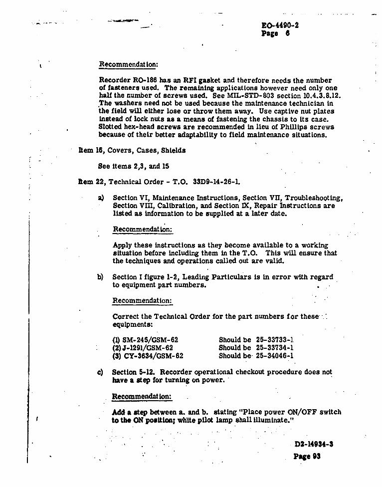
EO-4490-2Page 8
Recommendation:
Recorder RO-186 has an RFI gasket and therefore needs the numberof fasteners used. The remaining applications however need only onehalf the number of screws used. See MIL-STD-803 section 10.4.3.8.12.The washers need not be used because the maintenance technician inthe field will either lose or throw them away. Use captive nut platesInstead of lock nuts as a means of fastening the chassis to its case.Slotted hex-head screws are recommended in lieu of Phillips screwsbecause of their better adaptability to field maintenance situations.
Item 16, Covers, Cases, Shields
See items 2,3, and 15
Item 22, Technical Order - T.O. 33D9-14-26-L
a) Section VI, Maintenance Instructions, Section VII, Troubleshooting,Section VIII, Calibration, and Section IX, Repair Instructions arelisted as Information to be supplied at a later date.
Recommendation:
Apply these instructions as they become available to a workingsituation before including them in the T.O. This will ensure thatthe techniques and operations called out are valid.
b) Section I figure 1-2, Leading Particulars is in error with regard
to equipment part numbers.
Recommendation:
Correct the Technical Order for the part numbers for these-equipments:
(1) SM-245/GSM-62 Should be 25-33733-i(2) J-1291/GSM-62 Should be 25-33734-1
.(3) CY-3634/GSM-62 Should be. 25-34046-1
c) Section 5-12. Recorder operational checkout procedure does nothave a step for turning on power.
Recommendation:
Add a step between a. and b. stating "Place power ON/OFF switchto the ON position; white pilot lamp shall illuminate."
D2-14934-3
Page 93

EO-4490-2Page 7
Item 23, Figure A
The Technical Requirements section does not contain a paragraph
on Operability and Maintainability.
Recommendation:
Conform with AFBSD Exhibit 61-56 by supplying a paragraph onOperability and Maintainability in the Technical Requiremeptssection of the Figure A.
D2-14934-3
Page 94
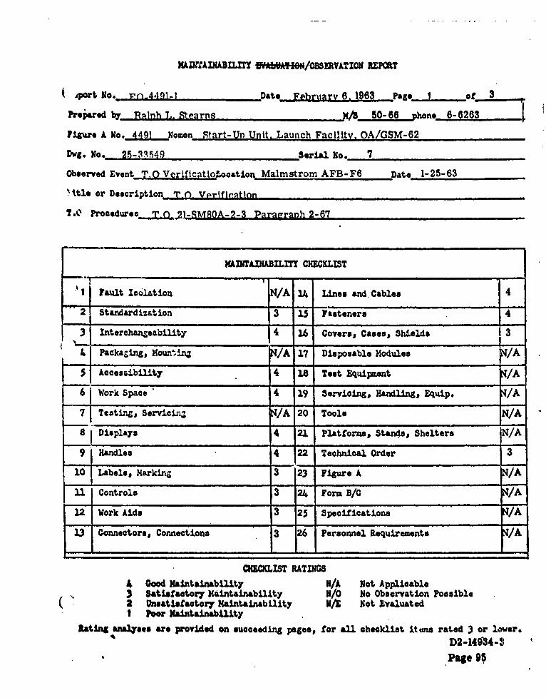
MAINTAI•A• ILIT EYA9 M"/OBSERWATION REPORT
.port feo ir•-.4.191-1 Date February 6. 1963 Page I o... .f 3
Prepared by Rahnh L. Stearns 6-6250-63
Figure A No, 4491 Nomen Start-Ur Unit, Launch Facility, OA/GSM-62
D! 8. No. 25-11549 Serial. No. 7
Observed Event T.O Verificatio5ocat~ion Malmstrom AFB-F6 Date 1-25-63
.. tle or Description T-0- VWrIfieation
TA Procedursc.Q.O _21 -SMROA-2-3 Paragraph 2-67
MAINTAINABILITY CHECKLIST
J I Fault Isatioin IN/A 14 Lines and. Cables 4""2 Standardization 3 15 Fasteners 4
3 '1Interchangeability 4 16 Covers, Cases, Shields 3
4 Packaging, Kounm~n, N/A 17 Disposable Modules I/A
SAccessibility 4 18 Test Equipment , /A
Work Space 4 19 Servicing, Handling, Equip. /A
7- Testingj, ServicinZ t/A 20 Tools IDisplays 4 21 Platforms, Standts, Shelters NIA
9 Handles 4 22 Technical Order
10 Labels, Marking 3 23 Figure A N/A
11 Controls 3 24 Form B/d /A
12 Work Aids 3 25 Specifications /A
13 Connectors, Connections 3 26 Personnel Requirements /A
CHiCKLIST RATINGS
4 Good Maintainabilitty N/A Not Applicable3 Satisfactory Maintainability N0 No Observation Possible
( 2 Unsatisfactory Maintainability N. Not EvaluatedI Poor Maintainability
Rating ana1~yses are provided on succeeding pages, for all checklist Items rated 3 or lower.
D2-149'4-SPaep 95

9O-4491-1 Page 2
Item 2. The power cable from the power pack, used with the Start- UpUnit, has a connector with a fine thread nut and plug.
Recommendation:
The connector and plug should be of the coarse thread, quickrelease type used on other Minuteman cabinets.
Item 10. The cable storage suitcase does not have a cable inventoryand cable location placard.
Recommendation:
To minimize the loss and damage of cables a cable inventoryand cable location placard should be fastened to the cover of thecable storage suitcase.
Item 1. The "ON-OFF" control for the start-up power to the G&Cgyrosopes consists of connecting and disconnecting the powerpack cable.
Recommendation:
An "ON-OFF" power control switch should be Installed on thepower pack.
Rem 12. A head set must be used and VRSA must be interrogated threetimes during start-up.
Recommendation:
With a fault code placard attached to VRSA the same resultscould be accomplished by use of the selector switches and indicatorlights. This would eliminate the need for a head set and theInterrogation of VRSA.
Item 13. See item 2.
Item 16. The cover to the test set suitcase can be installed only one waybut due to symmetry, has no readily identifiable method ofindicating the correct way.
D2-14934-3
Page 96

EO-4491-1 Page 3
Recommendation:
The cover and the case should be marked so maintenancepersonnel can readily discern the correct installationposition.
Item 22. A.The Technical Order does not note that for a certain period oftime the missile alignment light beam must not be broken.
Recommendation:
A caution note. should be included in the T.O.
B. An interim solution to Item 12 could be attained by a minor T.O.revision.
Recommendation:
The T.O. could be changed so maintenance personnel wereinstructed to use the VRSA selector switches and the VRSA codetable included in the T.O. This would eliminate the need for ahead set and the interrogation of VRSA, thus increasing theuseful life of VRSA.
D2-14934-3
Page 97

M"A-INAINABILITY EVALUATION/O!B1W*Z RUMT
4 Aeport No. r, - 4491-2 Date February 18. 1963 N -PIgs f 5
Fro'•wed bV Ralph L. Stearns K1.50-66 -phon .6-6263
: 1gure A No. 4491 Nomen Start-Un Unit. Launch Facility. OA/GSM-62
.. Dvg. No. 25-33549 serial 1.. 1
.- Observed Eventyvaluation LooationEDL Labratory ,DatesFebruary 15. 1963
Title or Desoriptior
T0o. Procedures________________________________
MUNMAINABILmT CHECKLIT
I Fault Isolation 4 14 Uines and Cables 4
-2 Standardization T 15 Fateners
.3 Interchangeability 4 16 Covers# Cases# Shields 3
.4 Packaging, Mounting 3 17 Disposable Modules N/A
5 Accessibility 3 18 Test Equipaent A
Work Spaoe 4 19 Servicing, Handling, Equip. NIA
7 Testing,, Servicing 4 20 Toole r4h0 Displays 4 21. Platforms Standes' Shelters N/A
"' .9 Handles 3 22" Techniceal OrerN/
•-0. La0e•@,, Marking 23 Figu•re A 3
"•1 Cootrls 4 2 rm B/C 3
12 Work Aids 22 Specifications
"23 Connectors, Connections 4 26 Personnel Requirements NIA
OIBCUJSTRATINGSS...,. , "' K� • ood Maintainability I/A Not Applicatble
' Satisfactory Maintainability ./N No Observation Possible2 Unsatisfactory Maintainability N Not Evaluated
Poor Maintainability
RAtJi analyrses are provided on'succeeding pages, for all checklist items rated 3 or lower.
,' . ' .. - . " . ' - . ,• .. ' • .'' • . .. -. ", . . * • 2-14934-

•0-4491-2 ," Page 2
item 4, Packaging, Mounting: .
''A.' The two suitcases, used to house the figure A equipment, are fragileand may not be capable of withstanding the rough field handling.i .. '_'_._.'_Recommendation:
The suitcases should be changed to the Zero Modular Packaging Systemtype per catalog E59 or similar.
B. When the top chassis is removed for service it is fastened to the lowermodule by a wire bundle. This makes the units very hard to handle and-no. doubt will result In damage to both the chassis and the wire bundle.
Recommendation:
The top chassis could be fastened to the lower unit by a hinge. If thisi s not practical the wire bundle should be made in two sections whichwould plug together.when assembled.
C. To remove the lower chassis from the suitcase the top uhit must be heldby one man, a second man' must h6ld.the suitcase in place, and a thirdman must lift the lower chassis out of the suitcase.
Recommendation:
Per MIL-STD- 803 paragraph 10.4.3.5.2 "Where possible, cases shall bedesigned to lift off units rather than units lifted out of cases."
D. To assemble the two chassis and the suitcase~drift pins must be used to"align the three units.
.-Recommendation:
Per MIL-STD-803 paragraph 10.4.3.7.5 "Guide pins or their equivalentshall be provided on unilts for alignment during mounting."
E. There is no easy way to discern the orientation of the two chassis and.-,.the suitcase.. •- -. ,
* - ... Recommendation: - -
"" Per MIL-STD-803 paragraph 10.4.3.5.1 "The proper orientation'of a unitwithin Its case shall be made obvious, either through design of the caseor by means of appropriate labels. , . ,"
" .. ' . . " " . " ' " " ". , ". " " , ,' .. P2 -14 9 3 4 -3
ppg. g,
. . . + .- • • , . .+ ., , . . . ... . . . ..j , . . . . , . . ..P :.. . o . • , .

EO-4491-2 Page . . 14. 3.
7 The spare fuses for the modules in the test set suitcase are mountedin the cable storage suitcase. . - * .. .,-
r Recommendation:
The spare fuses should be mounted in the same suitcase, readilyaccessible, and adjacent to the working fuses.
C.k To use either the self-test set or the break-out- box the maintenanceman must remove them from the suitcase.
Recommendation:.
By mn'unting the connector receptacle on the tops of these modulesthis requirement would be 'eliminated.
Item. 5, Accessibility:
Wire bundles located directly over terminal boards TBI, TB3, TB4,TB59 TB8, TB7, and TBS make the terminals inaccessible.
Recommendation: -
4 Relocate the wire bundles so the terminals are accessible.
Item 9, Handles:
'ADufing removal the lower chassis tends to twiht because the handlesare not located over the center of gravity..
* . Recommendation:
Per MIL-STD- 803 paragraph 10.4.3.2.2 "Whenever possible, handlesor grasp areas shall be located over the center of gravity of the unit sothat when the unit is lifted it does not swing or tilt.
Item 10, Labels, Marking:
A..The Iae for transformer 'IT 1", Is obscured by mounting board " "
- -~ . i:'Recommendation:.
"Change the location of the transformer label. .. 4 4. .
, A '.4>... *b2-14034-3
~~~~~Pi 100-~~- t 4.

.10.I-4491-2 P .
I .
B. It is difficult to locate the right positioning guide for the plug-in circuit
boards. ,"."
Recommendation:
Label the correct positioning guides.
C. It is difficult to determine which plug-in circuit board goes into which, receptacle. .. *
Recommendation:
Label the circuit boards and the receptacles with reference designations.
D. The abbreviation of "pounds" on the suitcases is "Ilbs."
Recommendation:
The abbreviation •'Wh" should be used'per MIL-STD-12B, paragraph 3.4.
,E. The name plates, on the test adapter and break-out-box chassis, are
not visible when the modules are in their correct mountings.
Recommendation:"" .
S. -. Locate the name plates so they are visible.
. ,• 'mIt 15, Fasteners: "
S-� " . The circuit card retaining cover is held in place by phillips screwswith flat washers wuider the heads.
Recommendation:
As the Washers are not required and will be discarded by field personnel. : money can be saved by not using them.
B. Phillips head screws and bolts are used through out the test set. This-., type of head is susceptible to ruin while being removed.
S" Iecommendation:Use ba-head screws and bolts in place of phillips head.
;- "' "='•-:''" 4 ' . • '1 . . I...
" . . . - ' ' " ;.. ' ,, -7 . I. A. . " " ., .
, ; :, " ;". ,• :•'. " , " • , , .... *- .. ... P ag e 101. . .. . . .. . . . . . *. ... .I . 4* . . , . • . . , . :: : : : . , . , ' . ,1'U l 4,V

. 2 K0-4491 2 . ... P age 5S.. . ..
qe . -4
C. The :aountings for capacitors C2 and C3 are held in place by bolts and. nuts. This requires the use of a holding tool and a turning tool to* remove a part. ."
"Recommendation:
When a nut is required use a captive type nut.
Item 16,'Covers, Cases, Shields:
The cover to the test set suitcase can be installed only one way butdue to symmetry has no readily identifiable method of irndicating thecorrect way.
Recommendation:
The cover and the case should be marked so maintenance personnel canreadily discern the correct installation position.
Reom 23, Figure A:
S The FigureA does not containany Maintainability Design Requirements.In accordance with AFBSD exhibit 61-56 Maintainability Design Require-ments must be included in the Figure A's for all OGE and MGEMinuteman equipment for which Boeing is responsible.
"Recommendation:
When the Figure A is revised Maintainability Design Requirementsshould be added.
oItem 24, Form B/C:
A. Line 4C of the Form C reads "blowers." There is only one blower.
"Recommendation:
On the next revision of the Form C change line 4C to -read "blower."
. B. Line 4a of the Form C instructs the maintenance personnel to remove"the test set case. The Form C does not instruct the maintenance personnelto put the test set back In the case.
R e c o m m e nd atio n : -. + . ,. .
.+ *'; 'b -the next revision of the Form C correct this condition.
• i,5''.
i7' i . ;-+•:. i (.+ " .' •Page 102

MDTAINTAzxrrh EVALUATIONABSO N-tOREPatCT
.1po't No.• ,n.Q..1'7-1 , ate February 25, 1963 Pago I of 3
P!1a•roed by HaR• h L. Stearns 50-66 -hone._-6262
Fi• we x Mo, .UL_ Noen Distribution Box J-1269/GSW-4
Dvg. Vo. 9.% 23468 serial MIo. 7
Observoii •vent_ E 'tjtInn, ,Location EDL Laboratory Date 2-22-63
Title or Description.
M.0. Prooedureo _ _ _ _ _ _ _ _ _ _ _ _ _ _
XLTWADIABILXTT CHECKLIST
1 Fault Isolation 4 1A. Lines and Cable. 4
"" 2 Standardization 15 Fasteners 3
3 Interchangeability I/A 16 Coversi Cases, Shields 3
is Packaging, Mounting 3 17 Disposable Modules N/A
5q Accessibility 3 18 Test Equipment NiE
6 Work Space 4 19 Servicing, Handlings Equip. N/E
7 Testing, Servicing 4 20 Tools 4
8 Displays 4 21 Platfornms Stands, Shelters N/A
9 Handles 4 22 Technical Order 4
10 Labels, Marking 3 23 Figure A 3
ft11 Controls 4 24 Form B/C
4
23 Connectors, Connections 3 26 Personnel Requirements N/E
CHECKLIST RATINGS
4 Good Maintainability N/A Not Applicable3 Satisfactory Maintainability N/O No Observation Possible2 Unsatisfactory Maintainability7 .Not EvaluatedI Poo• Maintainability
Rating analyses are provided on succooding pageso for al checklist ii-eaw rated 3 or lower*
D2-14934-3Page 10,3

EO.1337-1 Page 2
* Item 4, Packaging, Mounting
A. The two large access panels must be supported and aligned bythe technician while he is trying to install the retaining bolts.
Recommendation:
Per MIL-STD-803 paragraph 10.4.3.7.5 "Guide pins or theirequivalent shall be provided on units for alignment during mounting."
B. To remove relay K3 the wiring to relay K2 must be removed.
Recommendation:
Per MIL-STD-803 paragraph 10.4.2.3.3 "All throwaway assembliesor parts are accessible without removal of other components."
C. Due to the location of cable connector receptacles J30, J32, J33 andJ34 it is almost impossible to remove the cables withuut first removingother cables.
Recommendation:
Per MIL-STD-803 paragraph 10.5.2.1.2 "Connectors shall be locatedfar enough apart that they can be grasped firmly for connections anddisconnections. Space required will depend upon the size and shapeof the plug."
Item 5, Accessibility
See Item 4 paragraph "B" and "C".
Item 10, Labels, Marking
Part of the label for circuit breaker No. 6, VRSA Emergency Power,is hidden by a mounting screw.
Recommendation:
Per MIL-STD-803 paragraph 5.2.4. "Labels should not be hiddenby units and parts. For example, labels on the chassis should notbe placed under the parts which they identify. Also 'see MIL-STD-130B. Paragraph 4.2."
Item 13, Connectors, Connections;
Bee Item 4 paragraph "C." ,
P2:-14934-3~'n-m VflA

9O-1337-1 P.. . . Page 3 -
(eRem 15, Fasteners
There are eighty -six hex-head bolts holding the two access
panels to the distribution box.
Recommendation:
Per MILM-STD-803 paragraph 10.4.3.7.1 "A minimum number ofscrews or bolts shall be used for unit installation."
eRem 23, Figure A:
The Figure A does not contain any Maintainability Design Require-ments. In accordance with AFBSD Exhibit 61-56 MaintainabilityDesign Requirements must be included in the Figure A's for allOGE and MGE Minuteman equipment for which Boeing is responsible.
Recommendation:
When the Figure A is revised Maintainability Design Requirementsshould be added.
kRem 24, Specifications
Model Specification, Distribution Box, (S-133-111-1-28), BoeingDocument D2-6600, has no reference to maintainability.
Recommendation:
Conform to MIL-M-26512B (USAF) section 3.2.6.
D2-14934-3
. PagNe 105


![IGOR GRABEC [00800] Personal bibliography for the period 1962-2007](https://img.pdfslide.net/doc/110x75/613d2dfa736caf36b75a4286/igor-grabec-00800-personal-bibliography-for-the-period-1962-2007.jpg)