Embed Size (px)
Citation preview
UNCLASSIFIED
AD 646 635
COMPARISON OF THREE THEORIES OF WATER-JET PROPULSION
John H. Garrett
ü. S. Navy Marine Engineering Laboratory Annapolis, Maryland
February 1967
Processed for. ..
DEFENSE DOCUMENTATION CENTER DEFENSE SUPPLY AGENCY
(§Q.SA[30IK]@(K}®y@(l FOR FEKMl SQCNTinC /WO TttHMCM. INFOMUTION
U. f. OCnUITMCNT Or COMMtNCI / NATIONAL •UftEAU Of STANOAKOS / INSTITUTE FOR APPLIED TECHNOLOGY
UNCLASSIFIED

m r
i^'O? ].Ci>
US. NAVY
MARINE ENGINEERING LABORATORY
D DC Md.fnirr'.Tr.mnn.nfPj^
0 ;i FEB141967
IbUDtSllirBluJ B
Dedicattd To PROGRESS IN MARINE ENGINEERING
I>i«*rtbtttion pf thlf documwit i» unliÄited. .,■■■'. x '■ - ■ ■ ■

Bi^,l^MI'll|l:
l'll,ll'lni
ife'i-Äüiri a rsr^ic'ifss
mm WmAMUTTMKt
ax - AVAIL iri/v wami
1
DEDICATED TO PROGRESS IN MARINE ENGINEERING
The Marine Engineering Uborntory in charged vith
the discovery of fundamental knowledge, the
development of new and unique equipment to meet
and anticipate new naval requirement», analysis
of Fleet machinery failure», and evaluation of
prototypes to insure high performance and relia-
bility in the fleet. Dedicated to progress in
navs? engineering, the Marine Engineering Lab-
oratory contributes to the technical excellence
and superiority of the Navy today ~ and tomorrow.
<xx><x>c>c<>c<>c><>
ANY MATTERS OF COMMERCIAL CONFIOEMCE INCLUOEO IN
THIS REPORT MUST 6F TREATED WITH ÖÜE RECARO FOR
THE SArCSüAROlNG 0? RROPRIETARV INTERESTS.
THE INFORMATION CONTAINED HERE IN SHAtt NOT BE
USED FOR AOVERTISlNa RüRROSES.
THIS REPORT MAS «EEN MAfMing ASSEMiLtO. IF
ANY RA6ES ARE MtSSIN«; PLEASE RtOUEST FROM HCL.

Comparison of Three Theories of Water-Jet Propulsion
Assignment 55 501 Technical Memorandum 484/66
February 1967
By John H, Garrett
\JA ii /Wtf J/)HN H. GARRETT
Approved by:
" %( ^^ CLi^xCk
K. M. HERRMANN
Distribution of this document is unlimited.

MEL Technical Memorandum 484/66
Distribution List
NAVSHIPS (SHIPS 2021) (2) NAVSHIPS (SHIPS 031) DDC (20) NAVSECPHILADIV DTMB Addressee (10)
ii

MEL Technical Memorandum 484/66
ABSTRACT
The three different approaches to derivation of for- mulae expressing the relations among speed, thrust, power, and efficiency of water-jet propulsion systems, as developed by Lockheed California Company; Virgil Johnson of Hydro- nautics, Incorporated; and Joseph Levy of Aerojet-General Corporation, are summarized and compared. Certain modifications and simplifications are incorporated, and terminology is modified as necessary to facilitate comparison.
The Lockheed system« which provides a method for including the weight and drag of the propulsion system in the optimization procedure, appears to be the more useful.
The problems of compromising the performance of the propulsion system at cruising speed in order to provide reasonable hump performance are briefly discussed
i

MEL Technical Memorandum 484/66
TABLE OF CONTENTS
Page
DISTRIBUTION XiST ii ABSTRACT iii INTRODUCTION 1
Considerations 1 Comparisons 1
WATER-JET PROPULSION FUNDAMENTALS 1 Ideal 1 Actual 3
SUMMARIES 5 Water Jet Propulsion for High Speed Hydrofoil Craft 5 The Design of Water-Jet Propulsion Systems for Hydrofoil Craft 10 Waterjet Propulsion System Study 13
WATER-JET PUMPS 21 PERFORMANCE MAPS 34 DISCUSSION 37 FUTURE PLANS 38 APPENDIXES
Appendix A - Nomenclature (2 pages) Appendix B - Technical References
v ;.^

h *
MEL Technical Memorandum 484/66
COMPARISON OF THRKE THEORIES OF WATER-JET PROPULSION
1.0 INTRODUCTION
The Ü. S. Navy Marine Engineering Laboratory is assisting the David Taylor Model Basin in the machinery aspects of the surface effects ship and hydrofoil pro- grams. Both of these programs may utilize water jets as the main propulsion method. In order to establish a base from which to initiate machinery system layouts as well as to identify areas requiring further development, a review of some of the principles of water-jet propulsion was undertaken. This is a summary of previous papers on the subject together with suggestions for further work. A list of the nomenclature used for this stud^ is contained in Appendix A.
1* i Considerations. Development of the preliminary design of a water-jet system involves the following steps as a minimum:
• Devising a rationale for optimizing the Vj/V0 ratio. The important factor is the method of incorporating various losses chargeable against the propulsion system, since these are primary considerations in determining the optimum jet velocity,
• Consideration of the compromises required to provide adequate performance at the hump condition, while retaining high efficiency at cruise.
• Determination of the relation between performance parameters developed under the two above items and pump design.
• Optimization of the system by iteration procedures.
1,2 Comparisons. The three studies,1»2^ provide three different methods for optimizing the Vj/V0 ratio. These are summarized and compared modifying the approach and the nomenclature of the originals where necessary to facilitate com- parison.
2.0 WATER-JET PROPULSION FUNDAMEKTALS
2.1 Ideal. The same basic approach to developing the theory of water-jet propulsion is adopted in all reviews of the subject. Considering first an ideal system, that is, one in which there are no internal energy looses, the thrust produced by the jet is equal to the Increase in momentum of the water:
T » pQ^-V^. (1)
Supertcripts refer to similarly numbered entries in Appendix B.

MEL Technical Memorandum 484/66
The useful work done on the vessel is equal to the product of the thrust and the veloc- ity of the vessel:
Useful work = T V0. (2)
i
i The power output of the pump is equal to the rate of Increase of kinet energy of the ^ water passing through the system:
or, expressed in terms of head produced by the pump:
Ppump = "««Hideal <4)
The Ideal propulsive efficiency Is equal to the ratio of the useful work done on the ship to the power supplied fay the pump:
TV ,
V-P2 (5)
= 70—'S 5 <5a)
Equating Equations (3) and (4) shows that, as would be expected, the potential energy of the water, as represented by the pump bead, is ideally equal to the kinetic energy of the water in the jet, less the kinetic energy of the intake water:
^ (Vj2 - V02) - pQgH|detl .
or
V.2 - Vo2
"ideal ^
1

1
MEL Technical Memorandum 484/66
The shaft power Input is equal to the power output of the pump (Equation (?)) f divided by the pump efficiency:
p-lr^2-vo2>' f7> 'pu J
or, using Equation (4),
pQg Hideal p = Bg£Lf (7a)
2.2 Actual. In an actual system, the power requirement is Increased by the amount required to overcome the frictlonal losses of the water in the inlet, ducts, and nozzle. It is convenient to express these losses in the form of the additional head required to offset the losses. As the losses are likely to be roughly proportional to the square of the velocity of the water through the system, the loss is equal to a constant times some velocity head.
vx2
HL
= k ^F-
The choice of V varies among the three studies being reviewed. Johnson uses the ship velocity, VQ; Levy2 uses the jet velocity, Vj; and Lockheed^ uses the velocity of the water in the inlet duct, Vj, The value of K varies, depending on which velocity is selected as the measure of the loss.
In any case, the equations for the ideal system are modified to represent the actual system by adding to tlw head supplied by the pump the additional head required to overcome the loss
Thus,
ideal L
V.2 - V 2 V ;
- J~5g-^+ k ^ • W
!f Vj is selected as the measure of Internal loss, Equation (9) becomes
a^)v2. v2
w - —ig—~ W <

MEL Technical Memorandum 484/66
If V is selected, o
V - (1 - k) V 2
Em 5i m
If V. is selected,
V.2 + kV.2 - V 2
H«J -^L 2_ (11)
If the difference of elevation between the outside water level and the nozzle exit level is substantial, the energy required to elevate the water may be included in the equa- tion as an additional pump input, so that
It should be noted that, in all of these equations, the "head11 is a measure ol energy with the dimension foot-pounds per pound of water and is not simply a dimension, feet.
Substituting the value of H from Equation (12) into Equation (4) and dividing by the pump efficiency to obtain an expression for shaft power input,
- JI1 i"/* "v.2 * " - v.2i- n31
Sobetttntlnf this vtlue for P In Equations (t>) and (5a),
«^•-j 'a 8 • W V V, ♦ kV a ♦ h-V z
J » o
2 Dividing the numerator and denominator of Equation (14) byV0* m expression with the jet vekttlty ratio Vj/V0 as the variable is formed, Equation (14) becomes
-J-5 ♦ k-i-*-2--i as) V/ V * VA
Z
O 0 0
I I I I I
•

T i
MEL Technical Memorandum 484/66
A plot of this equation for various values of k provides a series of curves with shape similar to those of Figure 1. The optimum Vj/V0 ratio can either be found graphi- cally from the plot or numerically by differentiating Equation (15).
Another expression for efficiency using H instead of V2/2g Is secured from Equation (7a).
^1 . ^tVVo>Vo
(V, - V ) V - IjL Q 0 • (16)
gH
It should be recognized that, in an actual system, the summation of losses contrib- uted by each of the components over a range of operating conditions cannot be pre- cisely evaluated by any such expression as k (Vx
2/2g). To analyse the losses of a specific design, it is necessary to calculate the loss to be expected in each element under an appropriate ran^e of parameters and then to optimize the system by itera- tion. Computer programming is almost mandatory to accomplish this with any pre- cision within a reasonable allocation of engineering manpower.
3.0 SUMMARIES
With this as a foundation, it is in order to proceed 4 a review of the differences in the detailed approach taken by the respective authors of the references:
3*! "Water Jet Propulsion for High Spe^d Hydrofoil Craft. M Johnson^1 basic assumption is that the summation of internal energy losses (except nozzle loss) is relateu to V0; that is,
V2
HL - k IT- Another factor, K, includes both the elevation and the loss heads. Thus,
K = k + Ü* v For coovenieace in developing the equations, Johnson uses the factor, H*, defined as the ratio of head produced by the pump to the dynamic head,
V 2
o

MEL Technical Memorandum 484/66
t
b

,.«-.^ .*„-;.,..,. ;.i.n,5.-.\..?;.-,-^--.^.v. «X.i i.-#v^i ;■■■,.,..;rf.-:; '.-'.^ --<:■ r-f :* !v, -^ :■■,;• - -N
I
MEL Technical Memorandum 484/66
If Equation (12) is solved for Vj, the following expression can be obtained:
I
Substituting Equation (17) in (16):
Substituting K and H* (defined above), this equation simplifies to
^ . 2 [(1-Kj-^-l], (18) 'pu
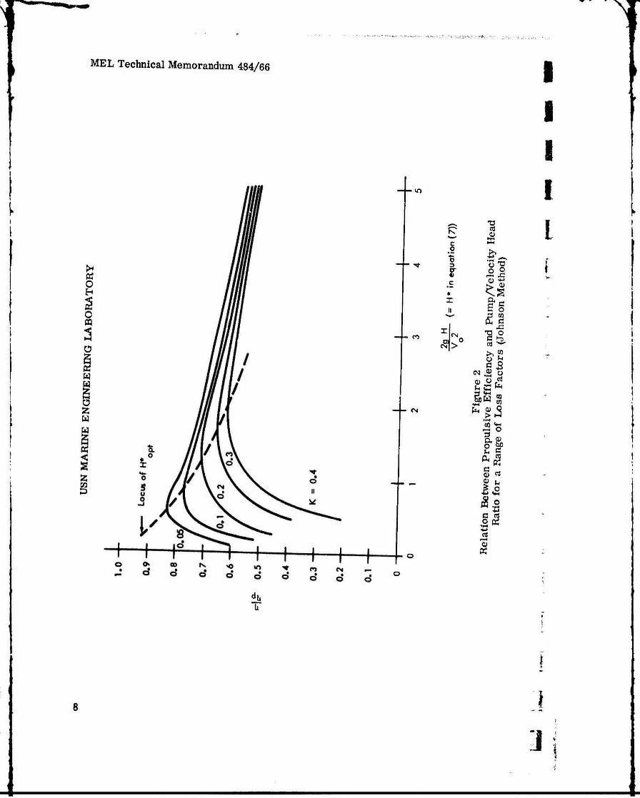
This is plotted in Figure 2 for the range of H* from zero to five and for several values of Kt Values of H* beyond five are generally not of interest (except perhaps at or below hump speed, where V0 is relatively low). By differentiating Equation (18), the following expression for H*0Dtimum results:
H*pt = 2K + 2Vir. (1.)
The locus of H* t is also shown in Figure 2.
Equation (19) implies that
V2
Hopt = T" ^ + ^^ (20)
A plot of H0pt against V0 for various values of K is shown in Figure 3.
An expression for Vj 0pt in terms of V0 and K can be derived from Equation (20),
Since
V2 v2
2g opt L 2g
2 2 2 V^ V V
i opt äH _ K o » JL 2g opt 2g 2g
7
MEL Technical Memorandum 484/66
c
p
§ o 2
o a
i i ■
i i
-«n i
- ^t
1 1 lo
city
Hea
d ho
d)
i
X o- ^ II E§
p CO 5 c -
- CO m 0 'g o e j3
oi|> ca sS' >»£ •* o b C5
re 2
fi
cie
Fac
- CN Fig
u
ive
Ef
Los
s
oQ «a f-H o ^ « i
g-ft
du b
3

MEL Technical Memorandum 484/66
o
3 &
W
Ü Z
Pi <
P
8 n
I 2LS
CO 0 Q. O
ss ■s ° ST
p m So CO
£ , .
O a §1
If II *J Op
I« o
i32J avlHlivnJWrBviI3o

MEL Technical Memorandum 484/66
Substituting the value of Hopt from Equation (19),
V 2 opt V 2 V 2
^_ (K + ViT, - ^ V
K + 2* *
This reduces to
V. opt opt I ^r— = tK + 2VK + 1 (21)
Figure 4 is a plot of Equation (21) for various values of K^
Johnson suggests that the minimum practical value of K for hydrofoil vessels will fall in the range 0.15 to 0.34, depending upon the size and speed,
3.2 "The Design of Water-Jet Propulsion Systems for Hydrofoil Craftn Levy makes the basic assumption that the summation of internal energy losses through the system bears a fixed relationship to the energy represented by the jet velocity, Vj2/2g. He adopts somewhat different terminology, in that he uses a term, k (here called r to avoid confusion with the loss factor k), such that
AV,VVo *-'
i
From Equation (3), neglecting Internal energy losses.
W pu (V4 - V)
Since
(Vo + AV)'
V02 a + r)2
PQV,
in pa h! - ■] (22)
pQVo2r
2»! (r + 2). P«
(23)
10

MEL Technical Memorandum 484/66
w O
I CO 00
s
mo
E 9
ido
^
I

MEL Technical Memorandum 484/66
The ideal propulsion efficiency, T V0/P, is then
n
= m* {25)
In order to take account of internal energy losses in the intake, ducts, and nozzle, a head loss coefficient K,, is adopted such that
V2
Taking account of the internal energy losses, the power input, Equation (22) is modi- fied as follows:
2 pQVo r 2 i
Substituting this value for P in Equation (24),
> a . V KL+2a+KL)r+ a + KL)r
I I
pQV^r I ^1-—T2 (24) 'pa pQV/,r(r+2)
I
(2C)
The optimum velocity ratio found by differentiating Equation (26) is
(27)
Equation (26) is plotted in Figure 1 for a range of KL from 0.1 to 0.4.
'« (.\)2 •
12

MEL Technical Memorandum 484/66
By substituting V. - V /V for r . in Equation (27) and noting that Jopt 0 0 op
V12 Vo2
(28)
an expression for optimum puir<p head in terms of V0 and KL can be derived as follows:
V - V ] opt vo
Vo
Vt = V jopt o ll + K + 1 (29)
Substituting this expression for Vj 0pt into Equation (28) results in the desired relationship
H opt
V * o
2g 0 * K^fe]
i
M, . 1 (30)
A plot of Equation (30) for several values of K^ is shown in Figure 5. A plot of optimum Vj/V0 ratio as a function of KL (Equation (29)) is shown in Figure 4.
In Appendix A of Volume 5 of the Lockheed "Wateriet Propulsion System Study. method is derived for establishing the optimum Jet velocity for a water-Jet
3.3 study3\ met propulsion system for a hydrofoil craft. The method depends upon knowledge of the various drag and loss parameters associated with the propulsion system and use of the concept of a basic ship, which is the vessel which would be required to carry the desired pay load and fuel if the weight of the necessary propulsion system were zero. The propulsion system is then charged with the additional drag resulting from the growth in size of the vessel required to carry the propulsion plant, as well as addi- tional drag due to propulsion appurtenanoe«, such as underwater struts or scoops.
The overall efficiency of the propulsion plant is defined as the ratio of useful work done on the basic ship to the shaft power output of the engine.

MEL Technical Memorandum 484/66
K O H
O S
o i—•
w w
Ü
u
<
f-f—f 8 8
8
C3
§ o
m M 'S
« c •n —»
I*!
Si 3 «
.0
8 § § 8 § K ^ ^) "» CO 8 8
4i 'pO»H dwnd «»rtwiidQ
14
J

MEL Technical Memorandum 484/66
ThV
% =-V- w The power required to propel the complete ship is TV, The difference between T V0 and Tb V0 is the power required to propel the propulsion system weight and to over- come the additional drag due to propulsion system appurtenances.
The overall efficiency can be divided into three elements, 77pi, 7)pU, and 1789 such that
% = w v P2> where rfoi u the ideal propulsive efficiency as defined by Equations (5), (5a}, and (6); 17pu is tne pump efficiency; and TJ8 it» tiie "system" efficiency, the definition of which will appear below.
The internal energy balance of the water-jet system requires that the net Increase in energy of the water in passing through the system Is equal to the energy added by the pump less the summation of Internal energy losses and the difference in elevation between the mean water level and the nozzle.
^rf-V*) = Opg{H-HL-h),
or
Vj2 - Vo2 = 2g(H-HL-h). (33)
The external energy balance requires that the net rate of increase in energy of the water, multiplied by the propulsive efficiency, is equal to the work done on the ship.
V ^ ^j2 - Vo2) = Tb Vo + Td V W
Since, from Equation (34),
Equation (31) can be transformed to
"P. ¥ (Vj2 - vo2) • Vo "0= -£ 1—T
i.-.
i
*..

I MEL Technical Memorandum 484/66 m
Since, by definition, |
r 'pu
n ri ,%£ (V42 - V 2) - n T^V
» , M P1^ ■ i~ ty; P" d o
'o QpgH
-^v vi2 -y va = pu pi -J-jpf r(3pgH
Substituting Equation (33)
'J-.. T^ V /H-HL-h\
VV H~/- r . , pu d o
% ~ npu V \ H /" QpgH *
This can be written as
(HT + h T. V \
o pu
The term between the parentheses involves the various internal and external energy losses attributable to the water*jet propulsion system and can therefore appropriately be called "system" efficiency, TJ .
From Equation (33),
V,2 - V 2
Substituting this value for Hin the expression for n in Equation (35),
V12-Vo2 Hd 2g n
n - n if ^ • (36) 8 v/ - V.
16
MEL Technical Memorandum 484/66
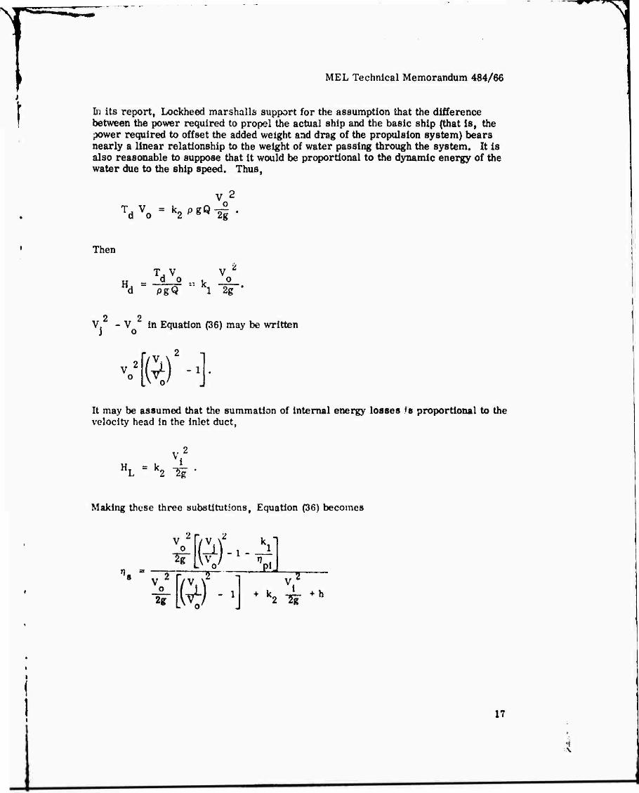
Di its report, Lockheed marshal Is support for the assumption that the difference between the power required to propel the actual ship and the basic ship (that is, the power required to offset the added weight and drag of the propulsion system) bears nearly a linear relationship to the weight of water passing through the system. It is also reasonable to suppose that it would be proportional to the dynamic energy of the water due to the ship speed. Thus,
TdVo = k2'*«li-
Then
T, V V Ä
u = d 0 ~ tr g ^d pgQ ' Kl 2g '
2 2 V - V in Equation (36) may be written
V [ft)!4 It may be assumed that the summation of internal energy losses fs proportional to the velocity head in the inlet duct,
HL - k2 Hi" •
Making these three substitutions, Equation (36) becomes
2 V
o w [fel m-]
T~
^ k2 I? +h
v

p* J'k I
^
MEL Technical Memorandum 484/66
Dividing by V 2/2g
Substituting the value of T? . from Equation (6) f
ft/-^
ft)-^ft o
From Equation (32)
"o Ä v V V
and from Equation (6)
i i
(37)
'Pi 2
73 v SubtUtuttog the vmlue of npt in Equation (6) in Equation (32).
an "o " —^ V
O
(38)
18

\
i 4-
MEL Technical Memorandum 484/66
' Substituting the value of TK from Equation (37) in (38), i s
,=2, — W ©
0 ' > /V .2 .V x2
By differentiating the variable, VjAo (treating all other values as constants), setting the result equal to zero, and solving for Vj/V0, the optimum value providing the highest overall efficiency can be determined. This operation is simplified if the constant terms in the numerator and denominator of Equation (39) are collected as follows:
\ ci =1 + y
V 2
C2-2ft) ^-^
Then
V.
W + C2
Differentiating and solving for V A;0 opt,
V i o opt
- C, + f;' ♦s ■
Substituting t his value of VjA'o
« 2 n
opt in Equation (40),
'7 (opt.
*C2 •
+ c2
(«)
19

MEL Technical Memorandum 484/66 |
Expanding the denominator, this becomes I
t) = 2r\ 1 » 0/ v \ P" , <42) |opt-/j 20^0^ + 0^2^ +2C2 £
Factoring the denominator, |
\
n Jc~ + c pu If i 2
pulf"l ' "2
(opt^j Vci2 + c2 (ci +K+ s)
pu
Cx + Vci2 + c5
"ou a (43)
o/ opt
Recalling that TJ0 = TJ ^ r^ T?S, and substituting the value of 7]0 (opt VjA^0) from Equation (43) and the value of rjpj from Equation (6),
'pu 's
$L -ft) Solvlngfor(V (44)
'opt
V
H v. L^\ 2% -i-
20
I i
fc
MEL Technical Memorandum 484/66
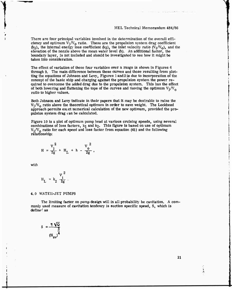
There are four principal variables involved in the determination of the overall effi- ciency and optimum Vj/V0 ratio. These are the propulsion system drag coefficient (ki), the internal energy loss coefficient (k2)t the inlet velocity ratio (Vj/Vo), and the elevation of the nozzle above the mean water level (h). An additional factor, the boundary layer, is not included and should be investigated to see how it might be taken into consideration.
The effect of variation of these four variables over a range is shown in Figures 6 through 9. The main difference between these curves and those resulting from plot- ting the equations of Johnson and Levy, Figures 1 and 2 is due to incorporation of the concept of the basic ship and charging against the propulsion system the power re- quired to overcome the added drag due to the propulsion system. This has the effect of both lowering and flattening the tops of the curves and moving the optimum Vj/V0 ratio to higher values.
Both Johnson and Levy indicate in their papers that it may be desirable to raise the Vj/V0 ratio above the theoretical optimum in order to save weight. The Lockheed approach permits exict numerical calculation of the new optimum, provided the pro- pulsion system drag can be calculated.
Figure 10 is a plot of optimum pump head at various cruising speeds, using several combinations of loss factors, kj and k2. This figure is based on use of optimum Vj/Vp ratio for each speed and loss factor from equation (41) and the following relationship:
with
v.2
4. 0 WATEll-JET PUMPS
The limiting factor on pump design will in all probability be cavitation. A com- monly used measure of cavitation tendency is suction specific speed, S, which is define'' as
?
.4
s =- -y
(V
21

MEL Technical Memorandum 484/66
i i Ü
w
I
C4 co ^r o o o o » li if ii
2*
2 o* o- 2 II II
>0*-\>0>r*
>-V
w
(ß
ß 0)
i 5
1 I I I
22

MEL Technical Memorandum 484/66
l *
§ w "♦ ^ 0 .-? ^ o
11 li II II
o — w > 5^ ^ .c
I I I I
-*L 0 >-t>
It OU
13
I ^
o .2 o S w
(4 o ^
O
I I l
w
23

MEL Technical Memorandum 484/66
g
Ü
w
w
<
s
o* o*o'of
u ii »
>i>c
^«■•.tfjff-.-.«**«.1
'S
s 0) CD s
Ü c
Ü
W
98 00 ^
g|
O Ü a
CO
E ■4-J
"S
I its w
-•-•—'"N/l
I I
du
ob
24
i

T W* J*
MEL Technical Memorandum 484/66
f
O H
O
w
w w
i CO D
1 i i
if I I it o
I I
CM CM CO
d
^ -^ > > -c
O
CM
00
>i><
+-4 00
#
0> fi
^ CO
I §
o a
w
1 25
N

u.
1 X
I a. E
a O
MEL Technical Memorandum 484/66
USN MARINE ENGINEERING LABORATORY
Crultt SpMd, V , knot, o
Figure 10 Relation Between Optimum Pump Head and
Ship Speed for a Range of Loss Factors (I<ockheed Method)
i i i
i
26

MEL Technical Memorandum 484/G6
where
n = Impeller revolution per minute.
Q = Discharge, gallons per minute.
H v = Net positive sunction head.
As applied to conventional double-suction centrifugal pumps, a value of S of 12,000 is found to be about the upper limit of cavitation-free operation. Thus,
JLVQ = 12)000
or
n VQ - 12,000 (H)4. (45) sv
Using the conventional definition of pump specific speed,
N -iüS ^8 3"
H 4
and substituting the cavltation-limited value of n VoTfrom Equation (45), the limit- ing value of N is
(# Ns « 12,000 1^1 . (46)
4.1 As applied to hydrofoils, and probably also to surface effect ships, it may be assumed th&t the maximum thrust of a water-jet system will be required at the hump transition, when the ship speed Is third or half the value of V0 at cruising speed. In order to provide this thrust, head and flow rate must be maintained at about the same level at hump and cruising speeds. Slnoe the net positive suction head will be lower at hump speed than at cruising speed, pump cavitation tendency will be greatest at hump speed.
27
^_

MEL Technical Memorandum 484/66
4.2 The net positive suction head (Hsv) Is the sum of the atmospheric pressure head plus the ram pressure head (reduced by internal friction and diffusion pressure losses), less the water vapor pressure head and the elevation of the pump above the water level outside the hull. If hump speed is half V0> HgV (using the approach of reference 1) will be approximately
33 + <-»$■)(£)- Substituting this value in Equation (46),
Ng = 12000 33
H
Remembering that K = k + 2gh/Vo ,
N = 12000 s
33 + -?r (1" ^ TI (47)
It will be noted that the internal energy loss calculated by this equation is a fourth that at cruising speed. Since the head and flow are to be approximately the same as at cruise» it seems reasonable to suppose that the internal energy losses would remain about the same. Accordingly, the present reviewer suggests that Equation (47) be modified to
N. 12000 33 + M V o
3t 214
IT (48)
This would, of course, lead to a somewhat lower cavitation-llmited value of Ns than Equation (47). In Figure 11, Equation (48) la plotted to show the relation between Ns and Vo for various K factors. For these curves, the optimum head is taken from Figure 3 for each V and K.
28

MEL Technical Memorandum 484/66
USN MiARINE ENGINEERING LABORATORY
10000"
1 i
8000--
3
6000
J 4000
2000—
CruittnQ Sp««d, KnoN
Figure 11 Maximum Pump Specific Speed at Limited by Cavitation
29
>
MEL Technical Memorandum 484/66
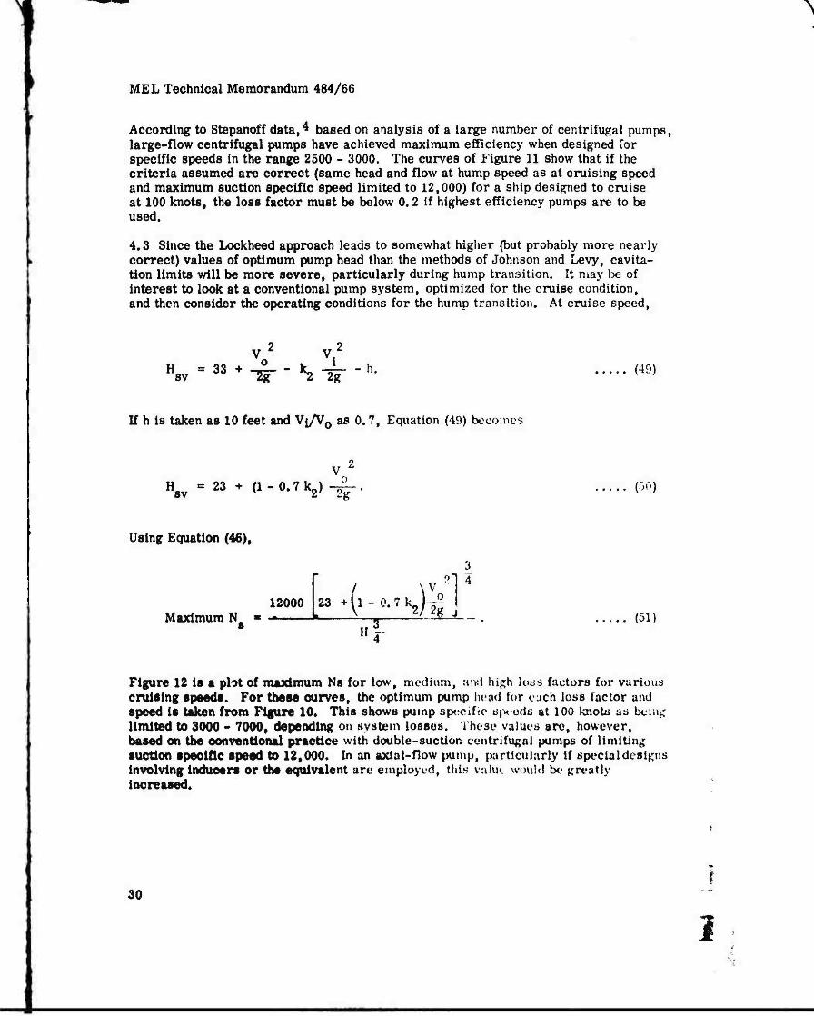
According to Stepanoff data,4 based on analysis of a large number of centrifugal pumps, large-flow centrifugal pumps have achieved maximum efficiency when designed Tor specific speeds in the range 2500 - 3000. The curves of Figure 11 show that if the criteria assumed are correct (same head and flow at hump speed as at cruising speed and maximum suction specific speed limited to 12,000) for a ship designed to cruise at 100 knots, the loss factor must be below 0.2 if highest efficiency pumps are to be used.
4,3 Since the Lockheed approach leads to somewhat higher (but probably more nearly correct) values of optimum pump head than the methods of Johnson and Levy, cavita- tlon limits will be more severe, particularly during hump transition. It may be of interest to look at a conventional pump system, optimized for the cruise condition, and then consider the operating conditions for the hump transition. At cruise speed,
H =33 sv + 0 - k -i
2g - h. (49)
If h is taken as 10 feet and Vi/V0 as 0.7, Equation (49) becomes
H8V *2$ + a-Q.?^)-^ (50)
Using Equation (46),
12000 Maximum N
3 l 4
_23.(x-0.7k2)^_
II (51)
Figure 12 is a plot of maximum NB for low, medium, ami high lo^s factors for various cruising speeds. For these curves, the optimum pump head for ouch loss factor and speed is taken from Figure 10. This shows pump specific s(x>eds at 100 knots as being limited to 3000 - 7000, depending on system losses. These values are, however, based on the oonventional practice with double-suction centrifugal pumps of limiting suction specific speed to 12,000. In an axial-flow pump, particularly if special designs involving Induoers or the equivalent are employed, this vafm would be greatly increased.
30
3

o I*
X
1
I
>
MEL Technical Memorandum 484/66
USN MARINE ENGINEERING LABORATORY
10--
9 —
8-- CwlfM
m — Hump 4
0
W ^ N^-N
• o.*
20 40 60 80 100
o
Figure 12 Civltation Limit on Maximum Specific Speed at Cruising Speed
31

MEL Technical Memorandum 484/66
The real cavitation problem, however, lies in traversing the hump region. This is because the thnst requirements here are nearly as high as, or possibly even higher than, at cruise speed, but the net positive suction head available, being nearly pro- portional to the square of the speed, is very much lower. Figure 12 also shows curves of maximum specific speed at the hump transition assuming that hump speeß is 40 percent of V0 and using the same cavitation criterion of 12,000 suction specific speed. For these calculations, the ship thrust-speed characteristics of Figure 13 are used, which show hump thrust and flow conditions essentially the same as at cruise speed.
At hump speed,
(fV)2
H8v = 33 + -2r--HL-h'
where f is the fraction of cruising speed (V ) represented by hump speed, and
Vi2
HL = KL "2^ *
The resulting cavitation limits for pumps optimized for different loss ratios and cruising speeds are shown as dashed lines in Figure 12. It will be observed that, if the configuration of the inlet, ducts, and nozzles remains the same at hump speed as at cruise, the flow rate required to provide the necessary thrust cannot be secured except with very efficient Inlets and ducts, or the net positive suction head otherwise falls to zero due to inlet losses. Therefore, it appears likely that either the inlet will have to be enlarged, or the nozzle constricted, or both al the hump condition, in order to increase the net positive suction head on the pump.
4,4 The widely reproduced chart of Stepanoff (Figure 5.1 in reference 4, page 76) indicates, on the basis of analysis of a large number of pump design, optimization of efficiency at a specific speed around 3000 for very large flow pumps. The optimum conventional impeller form for such a pump would be a so-called "Francis" type, where the flow is more nearly radial than axial. From Figure 12 it appears that as a "first cut" pump for a Urge surface effect ship, a specific speed of about 3000 would be appropriate, with suitable inlet and nozzle variat|on to provide a reasonable positive suction head at hump speed. It would undoubtedly be necessary to operate the pump in a cavitating condition during transit of the hump if tyc hump is in fact as pronounced as shown by Chaplin and Ford.^
1 f 32

MEL Technical Memorandum 484/66
§ <
<
»qi '^«u
I
I
3 «—I
I Ö 5-
'S
u >
E
33

MEL Technical Memorandum 484/66
5,0 PERFORMANCE MAPS
Levy2 shows two types of performance maps which are useful in matching pump characteristics to vessel characteristics, to one, the coordinates are head and capac- ity ratios; in the other, the coordinates are thrust and speed. ;
For the system head-capacity ratio chart, it is noted that Q is related to Vj in the ! following manner:
Q = V. A.,
or |
Vx* <52> Where Aj is the cross-sectional area of the jet at the maximum velocity section. ]
From Equation (28)t the head required to be supplied by the pump is equal to the jet velocity head plus the internal energy losses, less the velocity head resulting from the forward motion of the ship,
V.2 V2
"^^LJ^-IT-
Substituting the value of Vj from Equation (52),
2
2g * "■(W- V o
Rearranging,
Q
1
34 i

MEL Technical Memorandum 484/66
The ratio of flow at two different pump heads is then
% * /2gH2 + Vc Ql \2gH1 + Vo
2 (53)
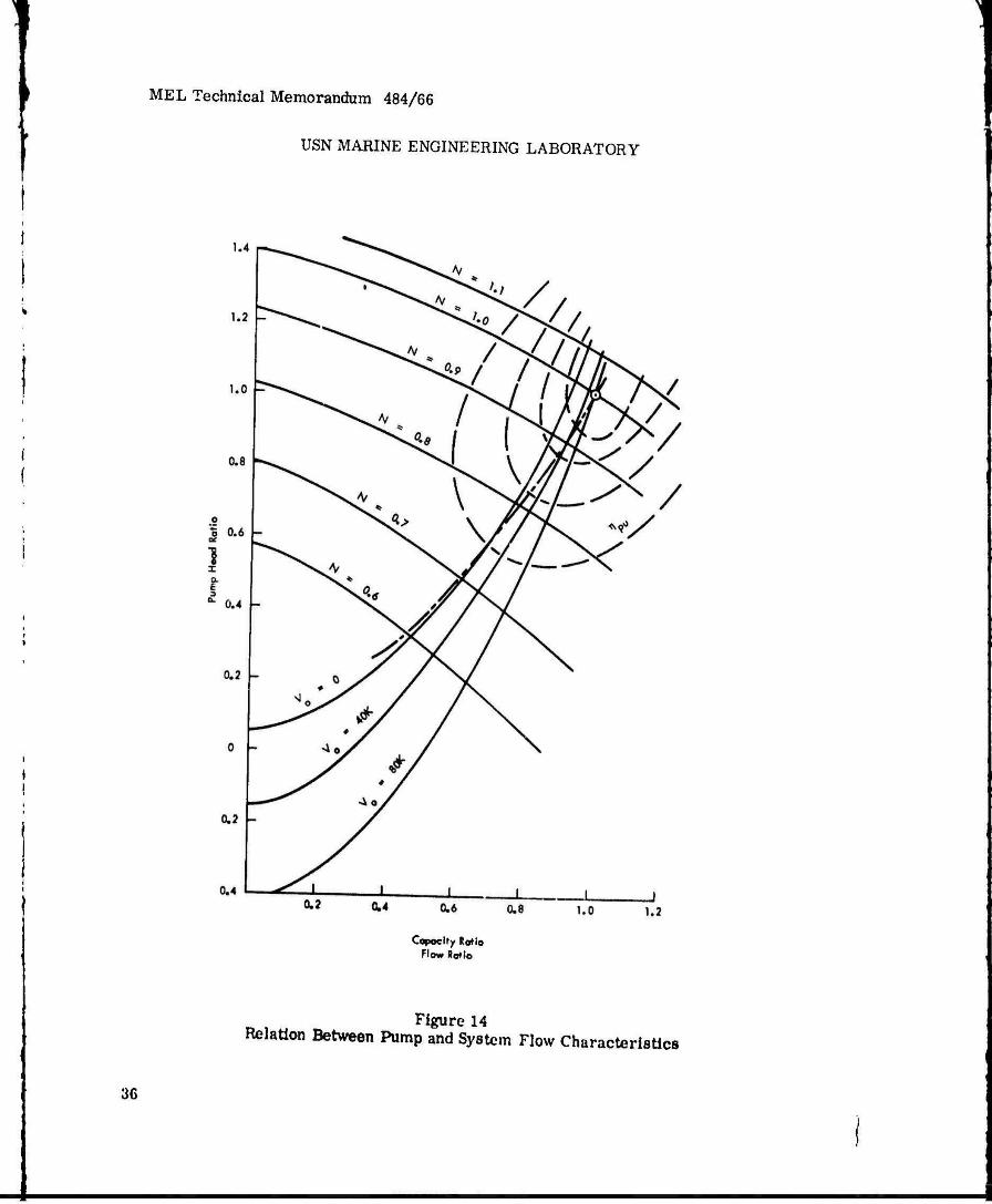
If Hi and Qi are the design point head and flow rate, the Q2/Q1 ratio for any other pump head can be calculated from Equation (53) for any speed. A series of curves similar to those shown in Figure 14 result.
Typical pump characteristics can be superimposed on the same coordinates, as shown in Figure 14. Then, if the thrust required for any selected vessel speed is known, and the pump speed required to produce this thrust is also known, the operating point in Figure 14 for any vessel speed can be found.
The pump speed required to produce a certain thrust can be computed as follows, if the pump characteristics, as shown in Figure 14, are known:
From Equation (28),
V.2 V 2
Rearranging,
V. = 2gH + V(
l + kT
1 2
(54)
From Equation (1),
T = pQ(Vj-Vp).
35
MEL Technical Memorandum 484/66
USN MABINE ENGINEERING LABORATORY
Capoclry Roflo Flow Ratio
Figure 14 Relation Between Pump and System Flow Characteristics
36

MEL Technical Memorandum 484/66
Substituting the value of Vj from Equation (54) into (1),
T = pQ 2gH + Vo
2
- V l+kL / o (55)
Since Figure 14 provides Q and H for any selected pump speed, all of the values nec- essary to compute thrust from Equation (55) are known.
Figure 13 shows the sort of curves which would result for a typical installation,
A curve of vessel drag in relation to speed can be superimposed on the same coordi- nates. A typical curve for a surface effect ship is shown in Figure 13. By finding the pump speed to produce a certain ship speed from Figure 13, the pump operating point can be directly located in Figure 14.
The cavitation point, assuming this to be a function of suction specific speed, can also be shown in Figure 13. Typical values for three different values of suction specific speed are shown.
6.0 DISCUSSION
It would appear that the Lockheed approach, by taking into account the effect on the optimum jet velocity ratio of differences in the weight and drag characteristics of alternative propulsion systems, affords a more useful approach to system design than those of Johnson and Levy, Also, relating internal energy losses to the inlet velocity, rather than to tue vessel velocity or the jet velocity, seems more realistic. Even so, the various k factors must be used with considerable caution. Relating inlet and duct losses to Vj2/2g is an obvious oversimplification. (Actually in the Lockheed study, a more direct approach of calculating and adding the individual sources of loss through the system is taken. The oversimplification Is due to the effort of the present writer to indicate principles rather than details.)
In particular, use of Vi as the measure of internal energy losses tends to mask the effect of diffuser losses in relation to duct wall friction losses, which may in some cases trend in opposite directions. For example, with a given flow rate, increased diffusion will reduce frictional losses, due to reduced duct velocity; but this saving will be partially offset by the loss in the diffusion process. Diffusion losses in this sense are not correctly accounted for in the equations presented here, and differences In inlet velocity ratio probably have less effect than shown In Figure 7,
37

MEL Technical Memorandum 484/66
7.0 FUTURE PLANS
In support of the Surface Effects Ship Program, further studies will be carried forward along lines of:
7t 1 Estimating the specific characteristics of surface effect ship water-jet systems based on use of conventional pumps of around 3000 specific speed suitable for use with the Pratt & Whitney FT-4A engine in a 4000-ton water-jet ship.
7.2 Similar estimates with respect to the 500-ton prototype ship,
7.3 Prelimlnaiy layout and weight estimates of the machinery plant for the 4000- and 500-ton ships.
7*4 Refinement of propulsion system drag and internal loss estimates in order to identify optimum pump characteristics with greater certainty. This will include quantifying the various loss coefficients and also developing better methods of taking into consideration the effects on required pump characteristics of diffuser losses and boundary layer Ingestion«
7,5 Development of optimum nonconventional pump designs.
38 ^
1

MEL Technical Memorandum 484/66
! 2 i
H*
Hd
k2
Appendix A
Nomenclature
Ci - ! + -5"
C2 " h fe)^-
2 g - Acceleration of gravity, fps
h - Difference in elevation between nozzle and mean water level, ft
H - Energy added to water by pump, ft-lb/lb
Ratio of energy added to water by pump to kinetic energy of water due to ship forward motion (Vo2/2g)f nondlmensional
Energy expended to overcome drag of propulsion system, ft-lb/lb
H. ~ Summation of internal energy losses, ft-lb/lb
H - Net positive suction head, ft-lb/lb
k - Ratio of internal energy losses to entering kinetic energy, nondlmensional
K - k + —^y , nondlmensional Vo
kj - Ratio of internal energy losses to jet kinetic energy, nondlmensional
k. - Ratio of power required to overcome propulsion system drag, to product of water flow rate and kinetic energy, nondlmensional
Ratio of internal energy losses to velocity head in inlet duct, nondlmensional
Pump revolutions per minute
Ng - Pump specific speed, n VQPM
I
• n4
Propulsive efficiency x pump efficiency
«
A-l * *

MEL Technical Memorandum 484/66
n , 77 - Pump efficiency
, 17 . - Ideal propulsive efficiency
rjo - Overall efficiency, r)^ r}^ r}g
T)O - System efficiency
h P - Shaft power applied to pump, ft-lb/sec
Q - Water flow, ft3/sec j In pump specific speed formulae, water flow, gpm i
V - V r « «1-——2. t nondimensional
o
3 2 4 p - Water density, slugs/ft , lb-sec /ft
S - Pump suction specific speed, —^r-
(H )4 v sv7
T - Total drag of ship = thrust of propulsive system, lb
T. - Drag of basic ship without propulsion system, lb «
T, - Drag attributable to propulsion system, lb
V. - Inlet water velocity relative to ship, fps
V. - Jet velocity relative to ship, fps
, V - Approaching water velocity, relative to ship = «hip forward velocity, at cruising speed, fps
AV - V Vo" ^
A-2
1
1 MEL Technical Memorandum 484/66
Appendix B
Technical References
1 - Johnson, Virgil E,, Jr., ,TWater Jet Propulsion for High Speed Hydrofoil Craft," AIAA, 29 Jun - 2 Jul 1964
2 - Levy, Joseph, "The Design of Water-Jet Propulsion Systems for Hydrofoil Craft," SNAME, 14 May 1964
3 - "Waterjet Propulsion System Study," Lockheed California Co., rept under Contract NObs-88605, 1965
4 - Stepanoff, A. J., Centrifugal and Axial Flow Pumps, John Wiley & Sons, Inc., 1957
5 - Chaplin, Harvey, and Allen Ford, Preliminary Draft of Design Principles of Ground Effect Machines, Section H, Supplement 2, Performance Graphs, May 1965

Unclassified Socurilv Classification
DOCUMENT CONTROL DATA -R&D ;Sfciifi7y classification of title, body of abstracl a/td iftdenlnj annotation must be entered when th« ovarall report la classified)
1 0«'GINA TING Acr\v\ry (Corporate author)
US Navy Marine Engineering Laboratory Annapolis, Maryland
2«.REPORT SECURITY CLASSIFICATION
Unclassified 26. GROUP
3 REPORT TITLE
Comparison of Three Theories of Water-Jet Propulsion
4 DESCRIPTIVE HOTES (Type of r*nort and Inelueive date*)
Research and Development Report 9 AU THOR(S) (Flrat name, middle Initial, laat name)
Garrett, J. H.
6 REPORT DATE
February 1967 7«, TOTAL NO. OF PACES
41 76. NO. OF REFS
5 8« CONTRACT OR GRANT NO
6. PROJEC T NO
0«. ORIGINATOR'S REPORT NUMBERIJH
484/66 »6. OTHER REPORT NO<S> (Any other numhmte that may he aetlgned
this report)
55 501 »0 DISTRIBUTION STATEMENT
Distribution of this document is unlimited.
■ioTPi t-MtN'» ART NOTES II SPONSORING MILI TARr AC'tVITi
NAVSHIPS
> * L> S r « A C T
The three different approaches to derivation of formulae expressing the relations among speed, thrust, power, and efficiency of water-jet propulsion systems, as developed by Lockheed California Company; Virgil Johnson of Hydronautics, Incorporated; and Joseph Levy of Aerojet-General Corporation, are summarized and compared. Certain modifications and simplifications are incorporated, and terminology is modified as necessary to facilitate comparison. The Lockheed system, which provides a method for including the weight and drag of the propulsion system in the optimization pro- cedure, appears to be the more useful. The problems of compro- mising the performance of the propulsion system at cruising speed in order to provide reasonable hump performance are briefly discussed.
(Author)
00.^1473 tPAGt i)
*.*h oin-*o7.«Ani Unclassified
Sccurm CUktificatton
Unclassified Security CU««ific«tion
14. KEY WOHOS
Hydrofoil craft Ground-effect machines Water-jet propulsion Lift, thrust Drag Cavitation Mathematical basis Pumps Velocity Hump condition Cruise speed Efficiency
DD .?rJ473 <•*«> (PAGE 2)
i nous. WT ROL E
!
Unclassified i

Ö 0
H IM 4i 0 •H • « • -«4 0 1 »i-» **
0 C-ri U 3 « • « 3 §'
SO 8 S ■ M &• O H
»-»OJ KN JtlAWMM
u i
If" I
5 2
5 V c
-H M
s f M
«11 S|M|!! *> u v ö c 5, o o •
O I
OB« Sh C g £ ^3 -H O
m IM
41 m *» §4*
z
OS • X S
in • ** -H M J: « u s ü -3 -H >
i *» o S -H
S-< « ♦»•3 -• > x *>
. •58' " I J.
S K
s
0» C 0
a o 85
n l'S 'S c ■* O -H -H 2 •« rp> • WM
t* •
IM 4Ji G
»•8
« 9 IM
W *> £
■ «M « M 0 -4
in « 4 • i •
3 W »
113
-^ *. g ^ <« • • • — Ölt-" •* *t •
ol^tl 3 ■ « «f 5
• JC
• - i ©■» •> ^ 2 -4 x M ^
«* M £ «* *l 0 *»
'8-81 .8 .•;,-§
I
— O
o -
a** a

I
IM
ß« r-« IM
u >, U * .-a * > -J Pi
I a. §
n 3
O «D 6 W
H OJ l<N it Lf\ H •-;
Ü 1 «1 V *-■
• <M V c 1 • «1
9 % 0 c U 9 • » u I .c * e -• a w *t V fl u *^ o • fi u if ff u <5 « •< > 5 a
Ü £ » • w a, e ^^ (TV <» jA r« f» »^
w t • o
• a. g » .j «4
8 f a o 0 • S « * ^ i »*'-"• » v « -^ > x *J ^«fj« — <Ofc.< b tr a.
4 * JE -. ^^^QV.Wfc-C
*-««*.' g tr i. ^ c m Jt n **
Si.
-* cr u ja c « o "^ ^ t-i a •a
« M 1-4
St J," • «
S8S 2 "^ P
■U ^ £
n *M « 14 o ^ « ä « « a a u c a c o
'?!
3 U «
I ] I