Embed Size (px)
Citation preview
UNCLASSIFIED
AD NUMBERAD099264
CLASSIFICATION CHANGES
TO: unclassified
FROM: confidential
LIMITATION CHANGES
TO:
Approved for public release, distributionunlimited
FROM:
AUTHORITYNRL ltr. 7103/113, 23 Oct 96; NRL lte.7103/113, 23 Oct 96
THIS PAGE IS UNCLASSIFIED
O~ilL %">r1T11II
Afrmed Services Tenhnical nforMati.nn gencyReproduced by
DOCUMENT SERVICE CENTERKNOTT BUILDING, DAYTON, 2, OHIO
This document is the property of the United States Government. It is furnished for the du-ration of the contract and shall be returned when no longer- required, or upon recall by ASTIAto the following address: Armed Services Technical Information Agency,Document Service Center, Knott Building, Dayton 2, Ohio.
rNiIUL: virEN GOVERNME','NT OR OTHER DRAWINGS. SPECIFICATIONS OR OTHER DATAARE TJSj) FOR ANY PURPOSE OTHER THAN IN CONNECTION WITH A DEFINITk;LY RELATEDGOVERNMENT PROCUREMENT OPERATION, THE U. S. GOVERNMENT THEREBY INCURSNO RESPONSIBILITY, NOR ANY OBLIGATION WHATSOEVER; AND THE FACT THAT THEGOVERNIJIENTI MAY HAVE FORMULATED, FURNZAHED, OR IN ANY WAY SUPPLIED THESAID DRAWINGS, SPECIFIC ATIONS, OR OTHER DATA IS NOT TO BE REGARDED BYTMPLj;(ATTON OR OTHERWVSE1 AS IN ANY MANNER LICENSING THE HOLDER OR ANY OTHERPERSO]T OR CORPDRATION, OR CONVEY•N•NG ANY R1GirfS OR PERI-CBMSION TO MANUFACTu1RE,USE jA. MELL ANY PATEN'TE INVENTION THAT MAY IN ANY WAY BE RELITED THERETO.

,9
ONFID ENT IAL NRL Report 4726
SIMULATION OF SONAR TRACKINGLO
J• [CONFIDENTIAL TITLE]
lit: C. H. Looney
Electrical Applications BranchSound Division Li:
May 22, 1956
-4
NAVAL RESEARCH LABORATORYWashiniqtun, D.C. 4'(
' n XT IV T In A* k- ¶ A V A A.A
,:'
CONFIDENTIAL
CONTENTS
Abstract ii
Problem Status ii
Authorization ii
INTRODUCTION 1
LIST OF SYMBOLS 1
THEORY AND GENERAL DISCUSSION 3
Relative Motion Computer 3Sonar Simulator 6
SAMPLES OF OPERATING PROCEDURE 8
DESCRIPTION OF COMPONENTS 11
Servoamplifier Al 11Servoamplifier A2 13Servo Integrator 14Range Inversion Amplifier A3 14Sonar Timer 15Power Supply 19
SUMMARY 20
APPENDD( A -- Mechanical Components 23
5eXLX ii A i.._
CONPIDENTIAL
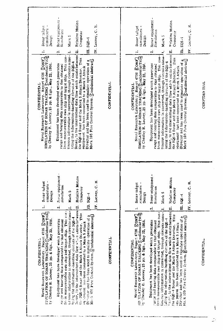
ABSTRACT[ConfidentiaiI
Equipment has been developed which gen-erates range and bearing data comparable iuthat obtained from maneuverable own ship andtarget -ship. This continuous information isconverted, through circuits simulating theinformation-handling cir cuits of the SQS-4Sonar, to the intermittent data flow which existsbetween the SQS-4 Sonar and the Mark 5 AttackDirector. This equipment has been connectedto a Mark 5 Attack Director and has been usedto simulate operation of a Mark 105 Fire Con-trol System.
PROBLEM STATUS
This is an interim report on one phase ofthe problem; work on other phases is continuing.
AUTHORIZATION
NRL Problem No. S05-13Bureau Problem No. C 4b-94
Manuscript submitted March Z1, 1956
1i CONFIDENTILAL
CONFIDENTIAL
SIMULATION OF SONAR TRACKING
t•oenfidential Title]
NTRODUCTION
The increased complexity of sonar --fire-control systems has created a need formethods of determining the compatability of equipment under development- Ultimatebhipboard evaluation is required in order to establish the merit of these new systems.Fleet exercises, however, are costly and time consuming; involve extensive preparationand planning; and require the use of scarce submarine time. In addition, difficulty isexperienced in obtaining data which is free of such undesired factors as operator error,variability of sonar conditions, uncertainty in target location, and dependency on recon-struction for the evaluation of weapon miss distance. Much information concerning thecompatability of equipments can be obtained prior to shipboard installation from labora-tory studies, which use inputs generated from known speeds and courses and are notdependent on a human operator for sonar tracking. A portion of this equipment would bea computer to generate range and bearing of the target from own ship; the remainderwould present to the fire-control equipment the target vange and bearing modified toinclude the delays inherent in the sonar equipment. The total equipment would be a simu-lation of the sonar equipment with maneuverable target and own ship to provide signals tofire-control equipment.
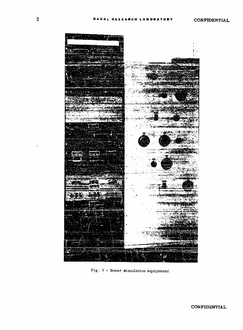
Simulation equipment, shown in Fig. i, which will achieve the desired performance,has been developed to investigate SQS-4 Sonar and Attack Director, Mark 5, operation.This report describes the Relative Motion Computer and the Sonar Simulator.
LIST OF SYMBOLS
St Target Speed
S. Own Ship Speed
ct Target Course
C. Own Ship Course
Bq True Bearing From Own Ship to Target
Brq Relative Bearing From Own Ship to Target
Rq Range from Own Ship to Target
A Target Aspect; angle measured clockwise from target course to line ofsound
AcRq Rate Aided Tracking: Range
AcBq Rate Aided Tracking: True Bearing
CONFIDENTIAL I.
2NAVAL WkLiEARCH LABORATORY CONFIDENTIAL
Fig. I Sonar simulation equipment
CONFIDENTIAL

CONFIDENTIAL NAVAL RESEARCH LABORATORY 3
jRq Correction to Range
j Bq Correction to True Bearing
> Amplifier
y Servomotor
r Tachometer Generator
Synchro Generator
@ Synchro Control Transformer
Synchro Differential Generator
S I Sine-Ctosine Mechanism
[j Ball-Disc Integrator
l] R-esolver
j• Mechanical Differential
EL Manual Input Knob
I Potentiometer
O Summing Point
THEORY AND GENERAL DISCUSSION
Relative Motion Computer
The Relative Motion Computer is an analog computer designed to receite inputs oftarget course and speed together with own ship course and speed, and to compute outputsof range and bearing of target from own ship. All computations are made on the basis offixed courses and speeds; however, the Relative Motion Computer can, at any time, accepta change in course or speed and compute on the basis of the new Information.
Figure 2 is a plot of a typical problem. (A list of terms and symbols is given to aidin interpretation of diagrams and equations.) Inspection of the angulRr relattons at ownship and target on Fig. 2 discloses these equations:
Brq - Sq - C0 (1)
A = -18o0 + Bq - C (2)
When the ships are proceeding on constant courses at fixed speeds, differentiating Eq. (1)and (2) with respect to time gives a third equation
d Bq d A d Bq
dt d t dt
CONFIDENTIAL
4 NA.VAL RESEARCH' LABORATOR'E CONFIDENTIAL
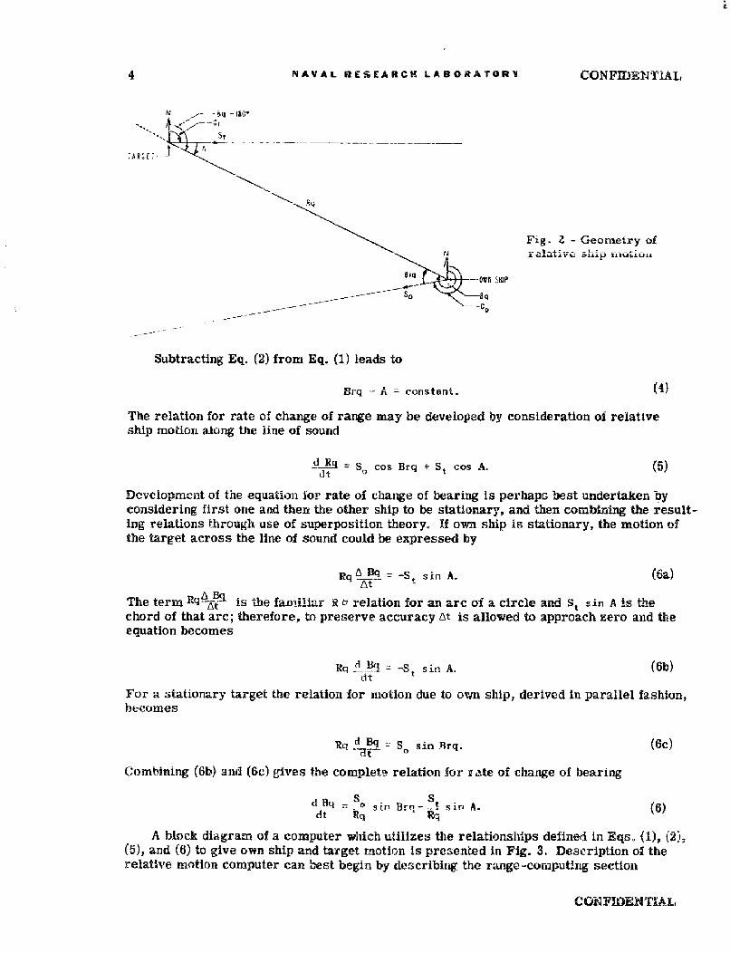
Fig. - Geometry ofN relative ship iaouiou
-Ofli SHIP
5 o SqC:O
Subtracting Eq. (2) from Eq. (1) leads to
Brq -A .= constant. (4)
'The relation for rate of change of range may be developed by consideration of relative,ship motion along the line of sound
dR = s cos Brq + St cos(A.dt
Development of the equation for rate of change of bearing is perhaps best undertaken byconsidering first one and then. the other ship to be stationary, and then combining the result-ing relations through use of superposition theory. If own ship is stationary, the motion ofthe target across the line of sound could be expressed by
Rq 8 1 = -S,, sin A. (6a)
At
The term R- iB is the fmiliar R & relation for an are of a circle and St sin A is thechord of that arc; therefore, to preserve accuracy At is allowed to approach zero and theequation becomes
lRq 4 B% = -S. sin A. (6b,)dt
For a stationary target the relation for motion due to, own ship:, derived in parallel fashion,becomes
Rq :d Bq - S. sin Tlrq. (6c)
Combining (6b): and (6c) gives the complete relation for rate of change of bearing
d .q - S 0 siri Brq-- - s in A. (6)
A block diagram of a computer which utilizes the relationships defined in Eqs. (1), (2),(5), and (6) to give own ship and target motion is presented In Fig. 3. Description of therelative motion computer can best begin by describing the range -computing section
CONFIDENUAL
CONFIDENTIAL NAVAL RESEARCH LABORATORY5
I 1I
-~C --- 0- W,! SQNAR SiMI>AT
RqR
K St ýU
SOS.. .d ,4 l
~i5fC vds/rev --CS~A IUAO
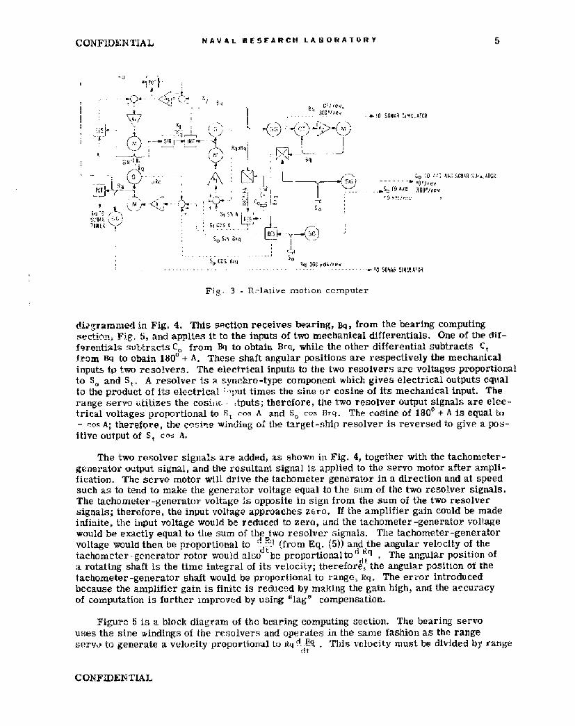
Fig. 3 fl lative motion comnputer
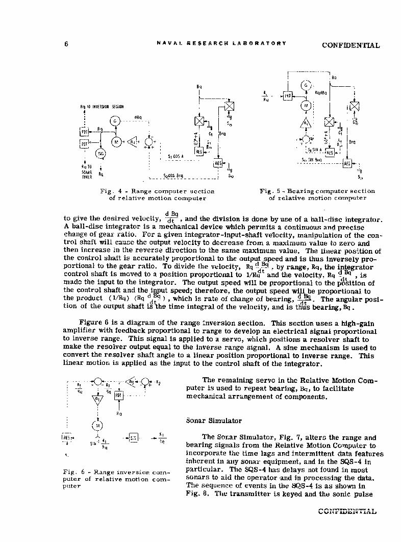
diogramnied in Fig., 4. This section receives bearing, Bq, from the bearing computingsection, Fig. 5i, and applies it to the inputs of two mechanical differentials. One of the, dii-f erentials subtracts C0, from Bq to obtain Brq, while the other differential subtracts Ctfrom Bq to obain 180Oo + A. These shaft angular, positions are respectively the mechanicalinputs to two resolvers. The electrical inputs to the two resolvers are voltages proportionalto S. and St. A resolver is a synch ro -type component which givesi electrical outputs cqttalto the product of its electrical 'pttimes the sine or cosine of its mechanical input. Therange servo isilizes the cosbiF .tputs; therefore, the two resolver output signab,; are elec-trical voltages proportional to, St cos A and S. co-, Brq. The cosine of 180' + A is equal to- cos A; therefore, the cqýyi winding oil the targret-ship resolver is reversed to give a pos-itive output of St co A.
The two resolver signals are added, as shown in Fig. 4, together with the tachometer-generator output signal, and the resultant signal is applied to the servo motor after ampli-fication. The servo motor, will drive the tachometer generator in a direction and at speedsuch as to tend to make the generator volt-age equal to the sum of the two resolver signals.The tachometer -generator voltage is opposite In sign from the sum ol the two resolversignals; therefore, the input voltage app~roaches ziro If thie amplifier gain could be madeinfinite, the input voltage would be reduced to zero, aind the tachometer -generator voltagewould be exactly equal to, the sum of the two resolver signals. The tachome~ter-g'eneratorvoltage would then be proportional to d Lý9 (from Eq. (5)) and the angular velocity of the
dta rotating shaft is the time integral of its vel~ocity; therefore, the angular position of thetachometer -generator shaft would be proportional to rangie, Rq. The erro~r introducedbecause the amplifier gain is finite is reduced by making the gain, high, and the accuracyof computation is further improved by using "lag" compensation.
Figurc 6, is a block diagram of the boaring computing ýsectiou. The bearing servouses the s~ine, windings of the resolvers and operates in the same, fashion as the rangeservoi to generate a velocity proportional to iiq!tJi .'This velocity must be divided by range~
dt
CONFIDENTIAL
6 NAVAL RESEARCH LABORATORY CONFIDENTIAL
10 q vWsINVERSION SECMN
dRqA
AtOS Sw StSIMT
Sr , SIt!
To ------ R-E- --RQ TO
USýChAR R
T!4ER S0C0S OrqsoS
Fig. 4 -Range computer section Fig. 5 - Bearing computer sectionof relative motion computer of relative motion computer
to give the desired velocity, Ai ' and the division is done by use of a ball-disc integrator.A ball-disc integrator is a mechanical device which permits a continuous and precisechange of gear ratio. For a given integrator-input-shaft velocity, manipulation of the con-trol shaft will cause the output velocity to decrease from a maximum value to zero andthen increase in the reverse direction to the same maximum value. The linear position ofthe control shalt is accurately proportional to the output speed and is thus inversely pro-portional to the gear ratio. To divide the velocity, R q d Np. by range, Rq, the integratorcontrol shaft is moved to a position proportional to I/R4 and the velocity. Rq ± , ismade the input to the integrator. The output speed will be proportional to the position ofthe control shaft and the input speed; therefore, the output speed will be proportional tothe product (l/Rq) (Rq d Eq) , which is rate of change of bearing, d _.. The angular posi-tion of the output shaft isihe time integral of the velocity, and is thJus bearing, Bq.
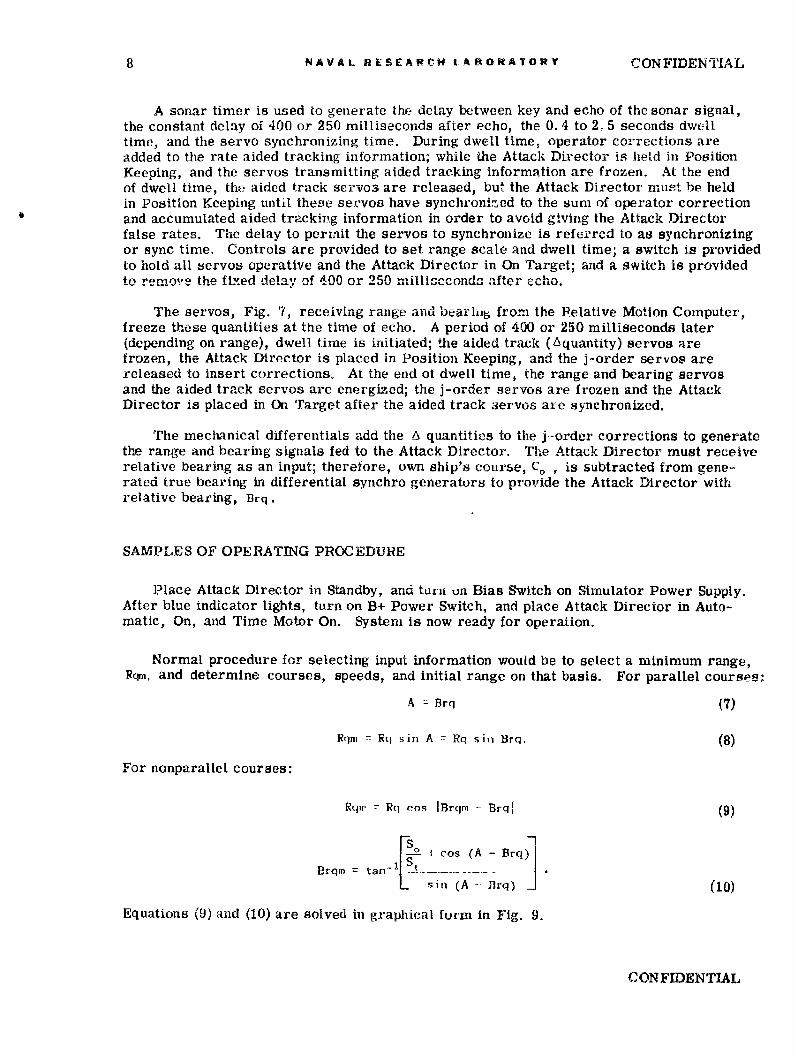
Figure 6 is a diagram of the range Inversion section. This section uses a high-gainamplifier with feedback proportional to range to develop an electrical signal proportionalto inverse range. This signal is applied to a servo, which positions a resolver shaft tomake the resolver output equal to the inverse range signal. A sine mechanism is used toconvert the resolver shaft angle to a linear position proportional to inverse range. Thislinear motion is applied as the input to the control shaft of the integrator.
-- ------ <A3 -- KThe remaining servo in the Relative Motion Com-
puter is used to repeat bearing, Bq, to facilitate
" .... mechanical arrangement of components.
Y I,, Sonar Simulator
-.- I4- I' The Sonar Simulator, Fig. 7, alters the range ands1- .- bearing signals from the Relative Motion Computer toincorporate the time lags and intermittent data features
inherent in any sonar equipment, and in the SQS-4 inFig. 6 - Range inversion corn- particular. The SQS-4 has delays not found in mostputer of relative motion corn- sonars to aid the operator and in processing the data.puter The sequence of events in the SQS-4 is as shown in
Fig. 8. The transmitter is keyed and the sonic pulse
CONFIDENTIAL NAVAL RESFAACH LABORATORY 7
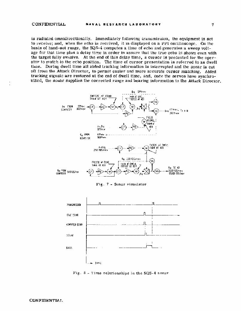
is radiated omnidirectionally. Immediately following Lransmiesion, the equipment is setto receive; and, when the echo is received, it is displayed on a P1-1 oscitloscopc. On thebasis of hand-set range, the SQS-4 computes a time of echo and generates a sweep volt-age for, that time plus a ,delay time in order to assure that the true echo is shown even withthe target fully evisive. At the end of this delay time, a cursor is presented for the oper-ator to match to the echo position. The time of cursor presentation is referred to as dwelltime. During dwell time all aided tracking information is interrupted and the sonar is cutoff from the Attack Director, to permit easier and more accurate cursor matching. Aidedtracking signalo are restored at the end of dwell time, and, once the servos have synchro-nizCd, the sonar supplies the corrected range and bearing information io the Attack Director.
BQ 5P-Iev
FREEZE AT ECL4O -1 ATHAWy iT KEY PDMT? AT MO
f _ _________6"Q
-. -- "- R E 1l
(r>Al BWL:
[HIAW C
250 ~ YOS/-r/,ve / A T9C
' FcE A! tEY-7 - T l IG AD
;•Oi YDRire>'i MT C-1 11ý'0 N~olDov"~ - - - -,T) -- 5> (i .m2C.Yý
Fig. 7 - Sonar simulator
TRANAMISSIV!N n-- _____
,:CLIPUEp (CRO J
Fig. 8 T ime relatione~ps in the SýQS-4 sonar
CUNFIDENTIAT,
8 NAVAL RESEARCH tABORATORY CONFIDENTIAL
A sonar timer is used to generate the delay between key and echo of the sonar signal,the constant delay of 400 or 250 milliseconds after echo, the 0. 4 to 2. 5 seconds dwelltime, and the servo synchronizing time. During dwell time, operator corrections areadded to the rate aided tracking information; while the Attack Director is held in PositionKeeping, and the servos transmitting aided tracking information are frozen. At the endof dwell time, the aided track servos are released, but the Attack Director must be heldin Position Keeping until these sevvos have sync hronhied to the sum of operator correctionand accumulated aided tracking information in order to avoid giving the Attack Directorfalse rates. The delay to permit the servos to synchronize is referred to as synchronizingor sync time. Controls are provided to set range scale and dwell time; a switch is providedto hold all servos operative and the Attack Director in On Target; and a switch is providedto remove the fixed delay of 400 or 250 milliseconds. after echo.
The servos, Fig. 7, receiving range and bearlng from the Relative Motion Computer,freeze these quantities at the time of echo. A period of 400 or 250 milliseconds later(depending on range), dwell time is initiated; the aided track (Aquantity) servos arefrozen, the Attack Director is placed in Position Keeping, and the j-order servos arereleased to insert corrections. At the end o1 dwell time, the range and bearing servosand the aided track servos are energized; the j-order servos are frozen and the AttackDirector is placed in On Target after the aided track servos are synchronized.
The mechanical differentials add the A quantities to the j-order corrections to generatethe range and bearing signals fed to the Attack Director. The Attack Director must receiverelative bearing as an input; therefore, own ship's course, C0 , is subtracted from gene-rated true bearing in differential synchro generators to provide the Attack Director withrelative bearing, Brq.
SAMPLES OF OPERATING PROCEDURE
Place Attack Director in Standby, and turn on Bias Switch on Simulator Power Supply.After blue indicator lights, turn on B+ Power Switch, and place Attack Director in Auto-matic, On, and Time Motor On. System is now ready for operation.
Normal procedure for selecting input information would be to select a minimum range,Rqm, and determine courses, speeds, and initial range on that basis. For parallel courses:
A = Brq (7)
Rqm = Rq sin A 7 Rq sin ]rq. (8)
For nonparallel courses:
Rqrr R(q cos IBrqm - Brq! (9)
B rq°. = an cos (A -B rq ) [
'L in (A- rq)] (10)
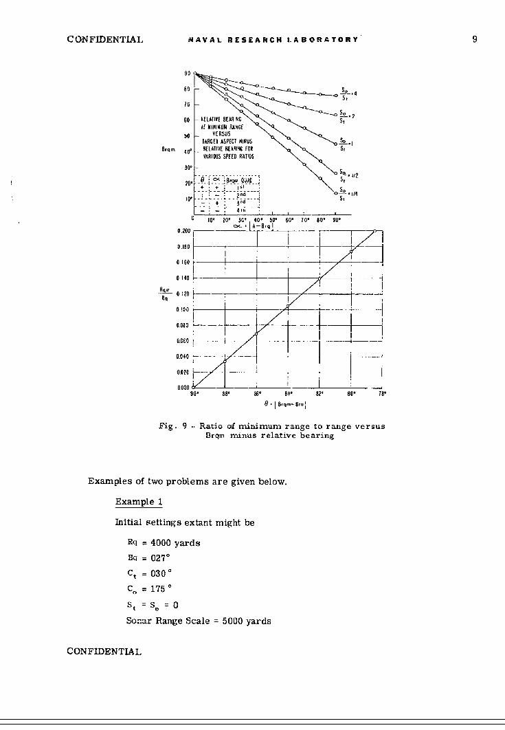
Equations (9) and (10) are solved in graphical form in Fig. 9.
CONFIDENTIAL
CONFIDENTIAL NAVAL RESEARCH LABORATORY 9
90
10 2
60 RELATIVE BEAR 4G T_0 VERSUS
T0 ARGET ASPECT MINUS -.oSo .18,q. 40. RELATIVE BEARIC FOR S5
VARIOUS SPEED RATIOS
30 -.f2
CK St
" - ............ " 9' 6' 1 ' oS0' 90' [--- I ----
_ _ _ _ _ _ __- _I
- 0 0 i---------- -- S" i
10' ?0' 3 0' 5 0' 82' 80' 90*
0.080-
Rq 40~000yrd
90, 88, 86. 84, 82' 80, T81
8.1 8,Q.-e Ora,
Fig. 9 .. Ratio of minimum range to range versus
Brqm miznus relative bearing
Examples of two problems are given below.
Example I
Initial settings extant might be
Rq = 4000 yards
Sq = 027°
Ct = 030
Co = 175 0
St 0so O
Sonar Range Scale = 5000 yards
CONFIDENTIAL
10 NAVAL RESEARCH LA BORATORY CONFIDENTIAL
Sonar Dwell Time - position 2
Test Switch 1: ON (all servos on)
Test Switch 2: OFF (fixed delay in).
Since the Attack Director wiil accept information firom 6000 yards in, computer rangeshould be set to 6000 yards and range and bearing repeating servos should be checked forsynchronism. If synchronism does not exist, turn off B+ Power on Simulator PowerSupply and adjust the servos to agree. Turn B+ Power on.
Select a minimum range for parallel courses, for example: 200 yards. (Note: Mini-mum range should be in excess of 100 yards.) Deteria-An initial aspect:
A, sin-i 200 = 1.90 = Brqi.6000
Determine Ct and C.:
Ct =180 + Bq - Ai
= 180 + 27 - 1.9 = 205.1°.
CO = Bq - Brq,
= 27 - 1.9 = 025.10.
Make the initial settings:
Rq = 6000 yards
Ct = 205.1 *
Co = 025.10
Sonar Range Scale: 10K yards
Sonar Dwell Time: Position 2.
Select speeds, for example, S, = St = 15 knots, and set these in; turn sonar test switch 1to OFF. Problem is now generating. (Note: the j-order range servo may lose synchronismwhen computer St minus Attack Director St is in excess of 15 knots, Attack Director Ctis not approximately computer Ct , range in excess of 4000 yards, and dwell time in excessof 0. 4 second (Position 1).)
Example 2
For the same initial conditions and the same Rq, select the angle (A - Brq) anda speed ratio So/St. From Fig. 9 determine Brqm.
Let A - Brq = 30
S0 =2.
Therefore, t
Brqm = 80.00
Rqm = 0.0333.RD
CONFIDENTIAL
CONFIDENTIAL NAVAL RESEARCH LABORATORY 11
Thus,Brqm - Brq = 88.10
Brqi = -0.10Ai = 21.90.
The initial settings would then be
Rq = 6000 yardsBq = 270C. = 35.10
Ct - 185.10S0 = 2 or S = 30 knots, St = 15 knots.St
The sonar timer range scale should be switched at the appropriate ranges and dwelltime should be changed to Position 1 as soon as the Attack Director has a nearly correctsolution as indicated by a small j-order correction.
The sonar timer test switch 2 may be turned ON to determine effect of eliminatingthe constant time delay after echo.
DESCRIPTION OF COMPONENTS
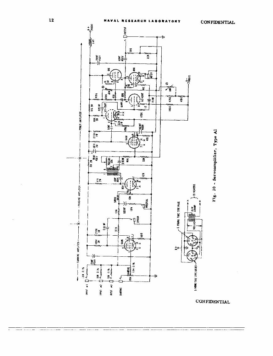
Servoamplifier Al
This amplifier, Fig. 10, adds a maximum of four signals in the summing amplifierstage, phases the resultant to be in quadrature relationship with the servomotor fixedfield, and then amplifies the signal to a maximum level of approximately 12 watts to beapplied to the servomotor control field. Jacks are provided for the inputs, for connectionto a lag compensating preamplifier, for output to the servomotor, and for metering.
The summing amplifier 1 is a 6AU'6 with 100% feedback to increase the input impedancefor the purpose of elimination of input interaction. The output signal should be equal to aninput signal applied to any one of the Input jacks or the Damping jack (with Damping controlset for full gain), but with 1800 phase shift.
The phasing amplifier uses a 0C4 to inject the signal into a phase shift circuitz madeup of a transformer, a capacitor, and a potentiometer. The circuit will provide about1350 of phase shift with slight voltage gain, and thus permits accurate phasing of the servo-motor control field voltage.
The power amplifier is a version of the "General Radio Signal-Ended Push-Pull" 3
amplifier designed to match the impedance of a Diehl FPE 25-11 servomotor. The 6AU6and first half of the 12AU7 provide voltage gain; the second half of the 12AU7 is the driverand the 6Y6's make up the power stage. The two screwdriver-adjust potentiometers areused to set operating conditions for the 6Y6's. A 100-ina meter is connected to the meter-ing jack on the chassis near the 6Y6's and a voltmeter is connected between chassis ground
iSeely, S., -Electron-Tube Circuits, " New York:McGraw--Hill, 1950, p. 19482 Chance, B., et al., eds., "Waveforms" (MIT Radiation Lab. Series No. 19),New York:
McGraw-Hill, 1949, p. 1363"General Radio Experimenter, " October 1951
CONFIDENTIAL
12 NAVAL RtESEARCH LABORATRoY ICONFIENTIAL
f-ii-Ix
P-4
M~
CONFIDENTIAL
CONFIDENTIAL NAVAL RESEARCH LABORATORV 13
and the blue pin jack. The two potentiometers are adjusted to give a voltage of 200 volt-and a current of 40 milliamperes. If "motorboatlng" develops, the simplest cure wouldbe to reduce the amount of voltage feedback around the power amplifier by reducing thevaiue of the 8. 2K resistor which is in series with a 91K resistor connected to the output.
The gain adjustment is vet to that value of gain just below servo oscillation.
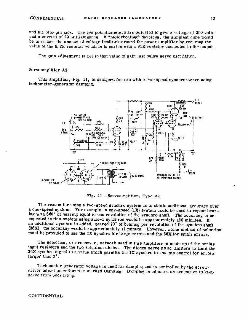
Servoamplifier A2
This amplifier, Fig. 11, is designed for use with a two-speed synchro-servo usingtachometer-generator damping.
bOS0 2 IVY
[--MALLORY -28 I 400YtF• I lf • Z + A50V --S48T4.
(NOT SC TYPE) 1O-, 100 A OUTPUT
47 18! 2 t1'TACKO IMTERN;MAIo. 005 ME I04RES CORP. -. 1408 T410
I I SrDAMPINGii 2plAir ITyF
82K D-IME 410KB23 1 4008
5 PRONG TUBE TYPE PLUJG 4101
5.I C 1ýL0 AMNPS NOT OTHERWISE MARKETsPRONG 1UB TO8AES RSsOR - ~ (08
Fig. 11 - Servoaxnplifier, Type AZ
The reason for using a two-speed synchro system is to obtain additional accuracy overa one-speed system. For example, a one-speed (IX) system could be used to repeat bear-ing with 3600 of bearing equal to one revolution of the synchro shaft. The accuracy to beexpected in this system using size-1 synchros would be approximately ±30 minutes. Ifan additional synchro is added, geared 10' of bearing per revolution of the synchro shaft(36X), the accuracy would be approximately ±1 minute. However, some method of selectionmust be provided to use the IX synchro for large errors and the 36X for small errors.
The selection, or crossover, network used in this amplifier is made up of the seriesinput resistors and the two selenium diodes. The diodes serve as ac limiters to limit the36X synchro signal to a value which permits the IX synchro to assume control for errorslarger than 3'.
Tachometer-generator voltage is used for damping and is controlled by the screw-dr'iver adjusi potentiometer marked Damping. Damping is adjusted as necessary to keepse-rvo from oscillating.
CONFIDENTIAL
14 NAVAL RESEARCIH LABORAATORY CONFIDENTIAL
The 12AX7 and the 6080 tubes operate in the same fashion as the 12AU7 and 6Y6 tubesin amplifier, Al. The operating conditions for the 6080 are set by connecting a 100-mameter to the metering jack and a voltmeter between ground and pins 3 and 5 of the 6080.The balance potentiometers are used to set current to 40 milliamperes and the voltage to200 volts.
Servo Integrator
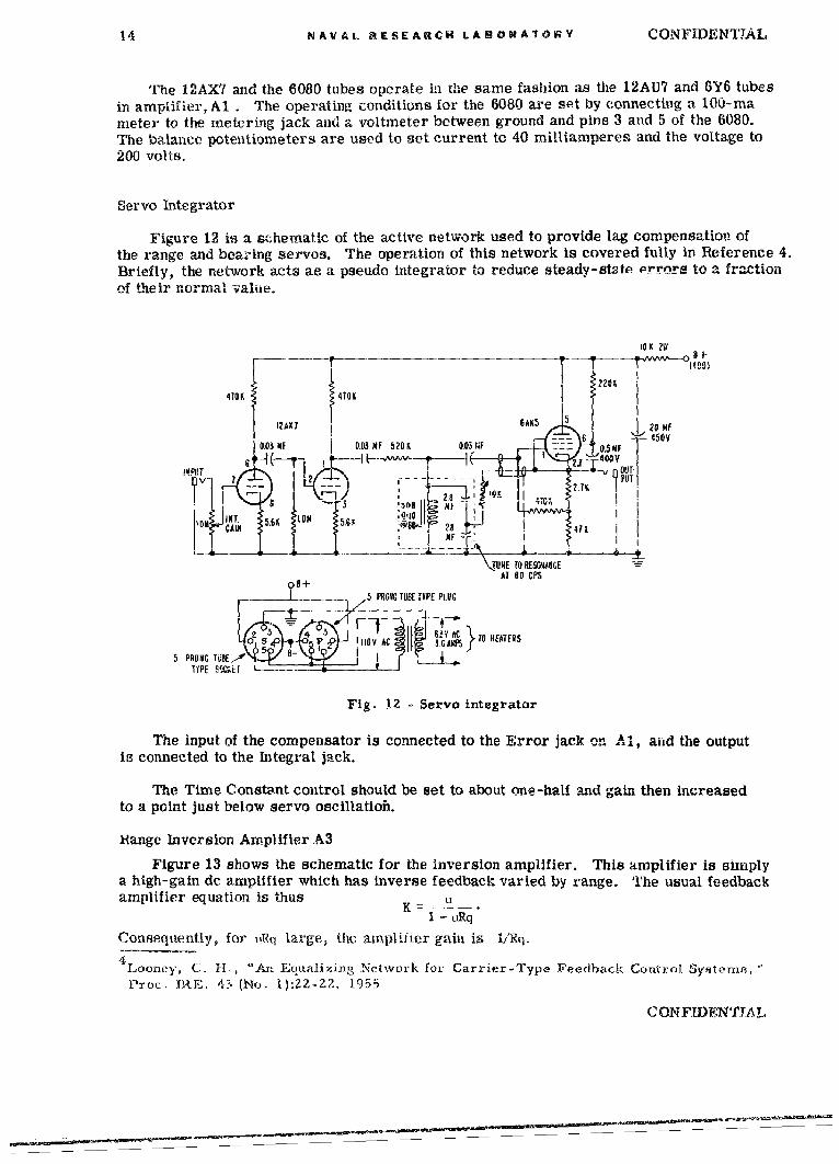
Figure 12 is a schematic of the active network used to provide lag compensation ofthe range and beazing servos. The operation of this network is covered fully in Reference 4.Briefly, the network acts as a pseudo integrator to reduce steady-state Prors to a fractionof their normal value.
IO X 211 a +
410K 4101 I
12AX? 6AO5 20 NF
03 ; - 00- 3 X f 0820 0.03Nt "' I O I
0NT [0fA : - I . 400V
I i: IJ MOT I
IN?_ -i __0,- -0 I- •j NFF
,~TUNE TO RESWAKE~AT 80 CPS
5 PRGMG TUBE IYPE PLUG
I:- - -_2 5 4 3 1 11y AC 67ACPS TO HEATERS
5 PRONG UBE Ir 5 a i lp IAP
"iPOE SMt;: I t L.
Fig. 12- Servo integrator
The input of the compensator is connected to the Error jack on AA, aid the outputis connected to the Integral jack.
The Time Constant control should be set to about one-half and gain then increasedto a point just below servo oscillatioh.
Hange Inversion Amplifier A3
Figure 13 shows the schematic for the inversion amplifier. This amplifier is simplya high-gain dc amplifier which has inverse feedback varied by range. The usual feedbackamplifier equation is thus U
I - LRq
Consequently, for tiRq large, the amplifier gain is i/Rq.
4 Looney, C. H , "An Equalizing Network for Carrier-Type Feedback Control Systems,
P'oc. IRE. 43 (No. i)2ZZ2, 1955
CONFIDENTIAYL

CONFIDENTIAL NAVAL RESEARCH LABORATORY 15
7-Vv 6+
IPAM' NC! 40
I;E I.PIT, i€; i+ M
- EL'¶ 01 i
ASHY i 0.05 22 9O..Slf "t Iu•Er j[- , - /N-
OPEIRAT ORAL 1 2mfAMPLIF,[RMCD. BY
G A. PL8R1CIC -
RESEARCHES, INC-
S.___5-PIGNCG TlBE T EPE PLUG
I' VI i • , : V AC TO HEATERS
5 -005KC TIRE 0ITYP4I 5301fQ r l l_ '
Fig. 13 - Inversion amplifier, Type A3
The only controls are balance and input voltage magnitude which determines linearityof the Relative Motion Computer. Balance control Is set by reducing computer range to150 yards and adjusting balance potentiometer for minimum 120-cps component in the errorvoltage of the main servoamplifier for this servo. Linearity is set to that point giving mostaccurate computation from 6000 yards in to a minimum range of approximately 200 yards.The best setting will, of course, be a compromise, but lineprity should be well within ±25yards of a straight line course.
Sonar Timer
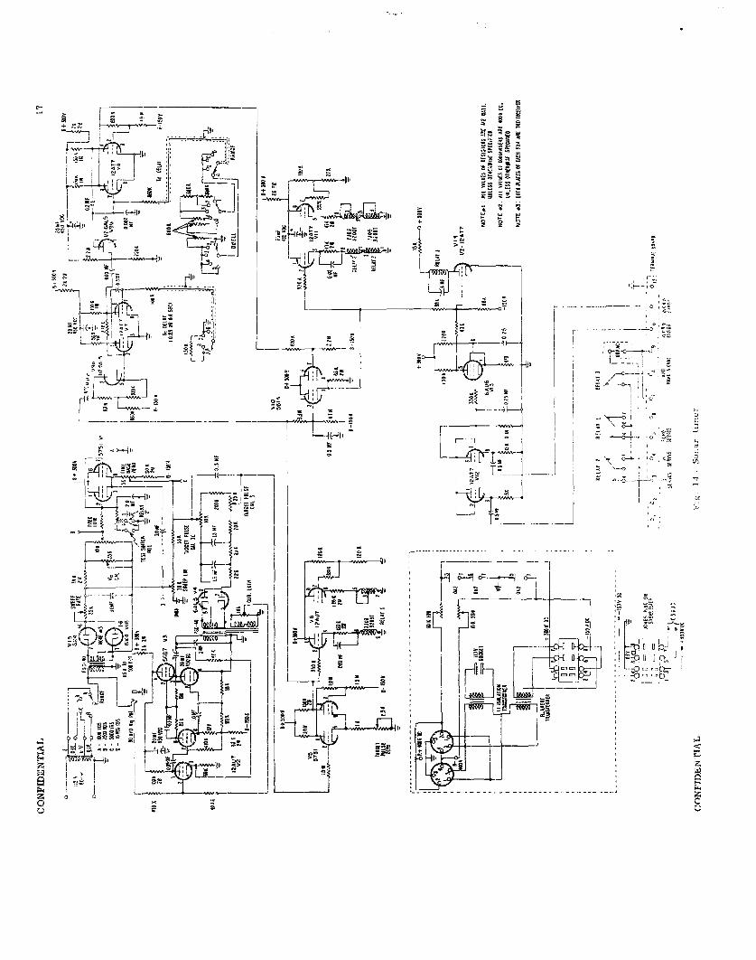
The Sonar Timer, Fig. 14, generates pulses at the time of keying the mock sonartransmitter, at the time the echo would be detected, at the er.n of the fixed delay T., andat the end of dwell time, Td. The timer also provides a delhy (during synchronizationof the A-quantity servos) before returning the Attack Director to On Target.
The time base is established by the circuit including Vi, V15, and V16. An ac volt-age proportional to the reciprocal of the range scale established by the range switch isrectified by Vib and V16 and then charges the 2. 0-MF capacitor connected to the gridsof V1. The tube V1 is a cathode follower used in a "bootstrap" circuit to linearize thecharge curve of the RC network made up of the precision 1. 0-M resistor and the 2. 0-MFcapacitor. The voltage from the cathode follower, Vi, is thus a linearly rising voltagehaving a slope proportional to the range scale selected-
This rising voltage could be termed a sweep voltage, and, in fact, is used as the PPIsweep voltage in the SQS..4. The time of echo is determined by subtracting a dc voltageproportional to range from the sweep voltage and triggering a multivtbrator at the timethis difference voltage goes through zero. The dc voltage proportional to range is developedfrom the circuit including tubes V2, V3, and lj4, and the pulse at echo is formed by tube V5.
CONFIDENTIAL
" XI"--7~
........ .......-...
1 Em
__Hi"•. •.- ,,•
4_. -.- •, • ;;--~ I r-T•••''•
L--------
- 1-- . . ---S - -I I, -: .= *
-I,-r• • -•;• T.. .
t0-
/ W4-0- - ,- !* ---?y;-- ,
J r •22" f" I -I -
;-rII'~ ~ ~ C D________
4~ 4...
0-
CONFIDENTIAL !NAVAL. RISEARCH LABOWORY 19
Tube V6 operates Relay I at echo time. A time delay of 400 or 25.0 milliseconds (depend-ing on range) occurs in the SQS-4 after computed echo to avoid the possibility of losing, theactual echo.. This de ý.y is generated by V7 and V9a. Dwell tim~e is established by tilemclivibtrator utilizing tubes V8 and V9b. The dwell time is varied from 0. 4 to 2. 5 secondsby the Dwell switch. Vll operates Relayo 2 and 2' during dwell time. V1O supplies a pulseto Vii during dwell time, or, if the dwell fim-e multivibrator is not triggered, VIO raisesthe grid of VIi to operate the relays when the sweep voltage has progressed to a point wellbeyond full scale. Relay 2' shorts out the sweep capacitor to ready the circuit for the nextcycle of operation.
Relay 1 's used to freeze the range and bearing servos to the range and bearing valuesaL the time of echo. Relay Z is used to freeze the A-quantity servos and to; thaw the i-orderservos during dwell time. The dwell time pulse is fed to tube V14 to operate Relay 3 whichputs the Attack Director in Position Keeping. Error signals from the A -quantity servosare rectified by V12, amplified by V13, and applied to: V14 to hold Relay 3 open until theservos are synchronized, thus keeping the Attack Director in Position Keeping during dwelltime plus synchronizing time.
Circuit adjustments are made primarily to set the slope of the sweep voltage and themagnitude of the range voltage to calibrate key-to-echo times. SQS-4 adjustments aremade on the basis of scope presentation, but, since the timer has no associated display,the adjustments are made in a differeMt manner. With test switch 1 turned ON, rangescale 1000, and range of 1000 yards, Time Base Zero is adj'isted to make the voltage fromjack C to jack A equal to zero, and Sweep Linearity is adjusted to make the voltage fromjack D to jack A equal to zero. V. Cal or V_ is adjusted to make the voltage from jack Bto jack D equal to 156* volts corresponding to a so-ind vlocity of 4800 ft/sec. Connectan oscilloscope Y amplifier between jack C and ground; turn X amplifier OFF; connect theZ input to pin 8 of Relay I socket, and connect a 1000-ohm resistor between the Z inputand ground. Set range scale to 2500 and simulated range to 2500 yards: with test switch 1OFF. Adjust oscilloscope gain so that the deflection from the position of the C-R beamduring dwell to the beam position when brightened is five squares. Set simulated rangeto 500 yards and adjust T. P. Zero to make the deflection from dwell position to brightenedposition one square. Return simulated range to 2500 yards and adjust T. P. Cal I or II tomake the deflection five squares. Repeat until further adjustments are unnecessary. Checkthe time from key to echo (brightened C-R beam) for simulated range of 2500 yards andrange scale of 2500. Adjust Sweep Rate to make the time equal to 3. 06 seconds.
Power Supply
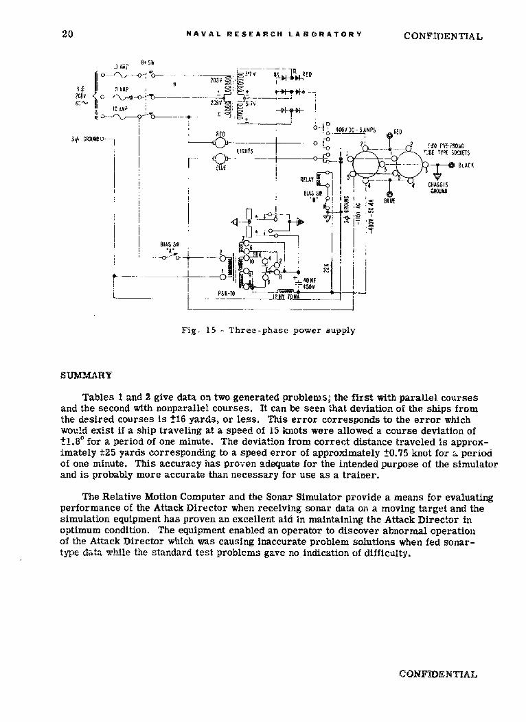
Figure 15 is a schematic of the power supply used by alt the servoamplifiers andassociated electronic instruments in the simulator and computer. Three-phase ac istransformed open delta and applied to a three-phase selenium rectifier which supplies+400 volts at 3. 0 amperes maximum. Single-phase ac is used to develop a bias supply of-400 voits at 50 milliamperes. A de relay is operated by the bias voltage to delay orinterrupt application of M+ until bias voltage is present. Current and voltage meteringjacks are provided for testing., A blue pilot light indicates presence of bias voltage and ared pilot light indicates B+.
20 NAVAL RESEARCH LABORATORY CONFIDENTIAL
.JOF - -- tI- /Nv1'7o. 6K ED
.,M AMP?C o~- - �--,- "lI0 SA ,
I 4 C-.5 ¾' J(} - -- "•iM.. .. -0• _ Ii , rO V-,O,
t!CHES!1 WUPRorW-~L G- HJBE Y+D([ gTY p.ST$
IL,.- BLACK
* SUE ~RELAYj--414 4 CHASSIS
IBIAS SW I CROUHD* --.B I~ : I ' BE/ ' , IE
t I
Fig 1 -ThIe~haj owr ITpl
IBIAS5W Ic-
s _j_ L0 [if9.- II _ _ _ _
Fig- i5 - Three-phase power supply
Tables 1 and 2 give data on two generated problems; the first with parallel coursesand the second with nonparallel courses. It can be seen that deviation of the ships fromthe desired courses is t16 yards, or less. This error corresponds to the error whichwould exist If a ship traveling at a speed of 15 knots were allowed a course deviation of±1.80 for a period of one minute. The deviation from correct distance traveled is approx-imately ±25 yards corresponding to a speed error of approximately 10.75 knot for -, periodof one minute. This accuracy has proven adequate for the intended purpose of the simulatorand is probably more accurate than necessary for use as a trainer.
The Relative Motion Computer and the Sonar Simulator provide a means for evaluatingperformance of the Attack Director when receiving sonar data on a moving target and thesimulation equipment has proven an excellent aid In maintaining the Attack Director inoptimum condition. The equipment enabled an operator to discover abnormal operationof the Attack Director which was causing inaccurate problem solutions when fed sonar-type da•ta the standard test problems gave no indication of difficulty.
CONFIDENTIAL
CONFIDENTIAL NAVAL RESEARCH LAE:ORATORY 21
TAIILE 1Data on Parallel Courses
C.0 000 Ct = 180 S. = is knots I St = iS knotsTnie - - "r •n'~roTisec) Eq j q Brq Eq Sin Brq Rqx Error Rq Cos Brq Rqy Iqy Error
0 6000 002.0 002.0 209 - 0f 6000
15 5720 002.1 002.1 709 0 5720 280
4S 1 5200 002.2 002.2 200 -9 5200 520 -915 4680 002.4 002.4 196 -13 4680 520 .
105 4160 002.8 002.8 203 -6 4160 520 -9135 3640 003.1 003.1 197 -12 3640 520 -9
1165 3120 003.7 003.7 201 -d 3110 530 +1
195 2580 004.5 004.5 202 -7 2570 540 +11
225 2060 005.7 005.7 205 -4 2050 520 -9255 1540 007.6 007.6 204 -5 1530 520 -9
285 1030 011.6 011.6 207 --2 1010 520 -9
315 540 023.5 023.5 215 *6 495 515 -14220 090.0 o9o.o 220 '11 0 495 I
375 610 160.0 160.0 209 0 570 570 _+3.51
1405 1100 169.6 169.6 199 -10 1080 510 -19 11435 1610 173.0 173.0 1% -13 1600 520 -9
465 2120 174.7 174.7 196 I-13 2110 510 -1949S 2640 175.8 175.8 193 -16 2630 520 -9
1525 3160 176.5 176.5 393 -16 3160 530 +1555 3660 176.9 176.9 198 -11 3660 500 -29
585 4180 177.2 17M.2 204 -5 4180 520 -9
615 4700 177.5 177.5 205 -4 4700 520 -91j645 5220 177.7 177.7 209 0 5220 520 -94675 5740 177.9 177.9 210 +1 5740 520 -9
6 6000 178.01178.0 209 0 6000 260
CONFIDENTIAL
22 NAVAL RESEARCH LARONATORY CONFIJJENTIAL
TABLE 2
Dats or. Nonparallel Courses
CO 186.1' C2 - 336.1ý S. a 1 knots S, ; 9 ¾iotsT0 -rq ii,8qi-r:q A•rqE r
(sec) ,q I li0 1 f3 Fq Cos Iurq-n-urq Rqx trrar Rq sinqirqn-8rqjRqy ErrRq.. E..;...Idi dev) I(de_ ) Ieg) (yd) - (yd) (yd) (d) yrl•.
0a 6000 178 -8.11 88.1 199 o 6000* 7 57601 178.1 -8.0 88.0 201 -2 5760 240
45 5320 178.2 -7.9 87.9 195 -4 5320 440 -5
75 4870 178.4 -7.7 87.7 196 - 4870 450 +5105 4420: 178.7 -7.4 87.4 7-n +1 4420 450 i5
135 3980 179. -711 87.1 1 201 -2 i80 440 5S
165 2-40i 179.3 -6.8 86.8 198 ' 3540 440 -5
1195 3090i 179.8! o 86.3 200 1 3090 450 -5225 2640 180.3 5.8 85.8 193 6 2630 460 +15
255 2200 181.2 -4.9 84.9 196 -3 2190 440 -5
285 1750 182.5 -3.6! 83.6 195 -4 1740 450 v5315 1320 i184.7 -1.4 81.4 197 2 1310 430 -15345 870 189.4 ÷3.3 J76 7 200 + 1 850 460 i +15
375 450 204.0 17.9 62.1 210 +11 400 450 t5
? 215 266.1 80.01 0 215 +16 0 400
435 R70 335.5 149.4 . 69.4 205 i +6 530 530 t20465 1000 345.0 158.9I 78.9 193 -6 980 450 -5
495 1450 348.6 162.5 82.5 190 -9 1440 460 15
525 1890 350.3 164.2 84.2 191 -8 1880 440 -5
555 2340 351.5 165.4 85.4 188 -11 2330 450 +5
585 2790 352.2 166.1 86.1 190 -9 1 2780 450 +5
615 3240 352.7 166.6 1 86.6 192 -7 3240 460 +15
645 3680 353.0 166.9 86.9 199 o 0 3680 440 -5675 4120 353.3 167.2 87.2 201 +2 4120 44
705 4570 353.6 167.5 87.5 199 0 4570 450 -5735 S0lO 353.8 167.7 87.7 1 201 '2 5010 440 -5
765 5460 353.9 167.8 87.8 200 +1 5460 450 +5
S6000 354.1 168.11 98.1 199 0 6000 540 -5
CONFI)ENTIAL
C OŽNFIDEN TAL,
APPENDIX AMechanical Components
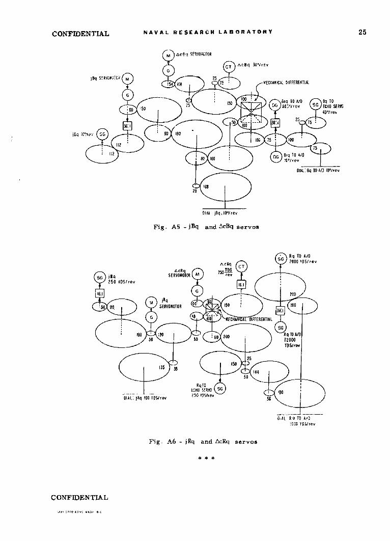
Figures Al through A6 are gear diagrams of the shaft relationships in the mechanicalcomponents of the Sonar Tracking Simulator and are included to give a concept of thephysical complexity of the equipment,
M dRq SE.YOnOI.ORVARiAC So, 15 VOiiSiso 6 TS
,, & A3S" G 0KITS
1O •rev
5eg P6 -9ag6,tesro pedscin
10- so ?4 9
ID l ~SIP CLUTICH GEAR
ML i: So
--• - -EV NO O --~ - --- --- --- ---TO ---
I C'r UTER ,---------- -, 500 lOSreve
LVARiAC 115 Yi OLTS
30KTS
50 15:DIAL: 5I
DIAL COmPUIER Rq.
1000 YDS/ rev
Fig.- Al - Range rate Bervo; speed sections
CONSE R1 MOTO Rd RT
6G CO PTER 0q. OrAL: COMPU'TER Bq .56011rev
24 40 10 44-2814
RE s :i MECHANICAL GO 144I - 4EWA
ý60 164 go:
/4 i00507 60I ikL 7
00N13W)EN l~t22
NAVAL WESEARC-U, LA• r .ATji--, CONFIDENTUL
ýV CCMP.J!E4 Bq SFRVO0!TOR
(~G RES
COMIPUTER l'q.24 • 360'Irev
i0
lOP OMPJIE Sq,24 44 144
IAd
q 144u•,iq.L •
CT60 MECHANICAL DIFFERENTIAL
102 24 144 / 12 60 12 )
SG ISG LCo.o ,/rev132 22
C o.386/01ev
24l~4 24
D~IAL' Co,101rev
Fig. A3 - Bearing repeating servo
ECHO A T RA 44ECHO 8q SERVONWO(\ ECII 1O Rq C ANO CAc sRVOS IVERVONIITROI 250 YOSirev
2 160 *G Q FROM C0OTERCT 10*He.
- 54 100 206 12
16020 396
so 16040 *25
Ra FROM15
COMPUTER CT
rev ALJ CHP Rq IOOQOOS/rev AN,SERVOS 401/rev D IAL.:ECHO Sq 101frev
C qFROM COMPUTER 360'1rev
Fig. A4 - Echo servos
CONFIDENTIAL
CONFIDENTIAL NAVAL RESEARCH LABORATORY 25
l SERVO$-,--CR M 5:54 UELU'C M 5 ECUNI:A!A 5IFFERENTiA!L
:60tA* 08 Tq To AID Aq TOL.6Tlrev SG ECHO SERVO
8DIL 6 r ev
01 IA TO"A/o)lrev
Fig. A5 .jBq and.±xc~q servos
SG IRq TO A/DAc~q CT2000 I0SIrev
tLcRq25 Ssc R'T SERVOMOOTOR -rev
250 IDS/rev
1g1- qc200
C50 96. SERVOMOTOR
G0 FORHA DIFFERENTIAL
18 :03 o 200 R qTO AID
TDSlrov
144
E^W S!RVO S6G 8
DIAL:. ]Rq 100 TOS/rae2oggte 5 :6 8
DiAL RQ TO A/':UG' YGS/rev
Figý A6 - jRq and AcRq servos
C ONF IDEN TIAL
-, aJ--c w;., Oc
> ; KC C IiLi am.. i
>.- .~
C)C I
C0:Z
tosr I c .r Cda
to~~ ~ CdQ t i r.~0 i d0 -M~J u 332-v..
Gi _ Coa, Cd COT Et 10
.0-0 U)L-~~~c- '5 CF2 UO C)
>~ ci Li Z1 >i 00 -- -C50
C Cc) 0 -0n E as-v CACU
Z~r S.z4c5 Q 0-
0 -d
C- aC.) 'n r Cr
-i C -i Cc,* cj:U. (d -. '
Li :j v i f%
H? ~ '. cor~C i
CE
_ C :
1U J a.. t1di;R.tna:A
Z0-9 Fa- ':,- i-i
Lu. 2 :5Z 2--4ý-
.6, 0 4 ) g
Cc m Li t %. C. C
t C ', 2 it I in
b.) CL C,
___ Z _ _ L3 _ _
C'TIAL
grmed Services echnical nf rmat0on ilgencyReproduced by
DOCUMENT SERVICE CENTERKNOTT BUILDING, DAYTON, 2, OHIO
This document is the property of the United States Government. It is iurnished for thit. di-ration of the contract and shall be returned when no longer required, or upon recall by ASTIAto the following address: Armed Servicem Technical Information Agency,Document Servtlo Center, Knott Blldin&, Dayton 2. Ohio.
NOTICE: WHEN GOVERNMENT OR OTHER DAWINGS, SPECIFICATIONS OR OTHER DATAARE USED FOR ANY PURPOSE OTHER THAN EN CONNECTIUn4 WITH A DEFIT•ELY R.,• .,EL AT, 1GOVERNMENT PROUR-EMENT OPERATION, THE U, S. GOVERNMENT THEREBY INCURSNO RESPONSIB!mITY, NOR ANY OBLIGATION WHATSOEVER; AND THE FACT THAT TdEGOVERNMENT MAY HAVE FORMULATED, FURNISHED, OR IN ANY WAY 43UPPIE) TIWFHSAID DRA-WINGS, SPECILFICATIONS, OR OTHER DATA IS NOT TO BE REGARDED BYIM2LICATION OR (THERWISE AS IN ANYr MAN•ER LICENSING THE HOLDER OR '\NY OTiHERPERSON OR CORPORATION, OR CC I'rIE G NTY PAGBU,. ,r-:, OR M, A "iJ . AC F;ICRE,USE OR SELL ANY PATENTED INVENTION TEIHAT' MAA IN ANY WAi U3E RELATE"D 'HRERETO.
I , -
UNITED STATES GOVERNMENT
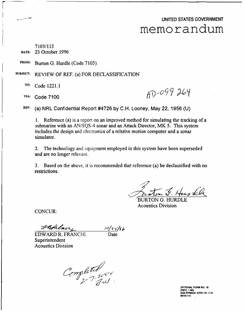
memorandum7103/113
DATE: 23 October 1996
FROM: Burton G. Hurdle (Code 7103)
sUB.cr: REVIEW OF REF. (a) FOR DECLASSIFICATION
TO: Code 1221.1
VIA: Code 7100 / •',
REF: (a) NRL Confidential Report #4726 by C.H. Looney, May 22, 1956 (U)
1. Reference (a) is a report on an improved method for simulating the tracking of asubmarine with an AN/SQS-4 sonar and an Attack Director, MK 5. This systemincludes the design and electronics of a relative motion computer and a sonarsimulator.
2. The technology and equipment employed in this system have been supersededand are no longer relevant.
3. Based on the above, it is recommended that reference (a) be declassified with norestrictions.
'BURTON G. HURDLEAcoustics Division
CONCUR:
"'/0/ 5;A kEDWARD R. FRANCHI DateSuperintendentAcoustics Division
OPTIONAL FORM NO. 19(REV). I .- )GSA FPMR(41 CFR) 101 -11.65010-114