Embed Size (px)
Citation preview

UNCLASSIFIED
AD NUMBER
AD451357
NEW LIMITATION CHANGE
TOApproved for public release, distributionunlimited
FROMDistribution authorized to U.S. Gov't.agencies and their contractors;Administrative/Operational Use; 22 oct1964. Other requests shall be referred toArmy Missile Command, Restone Arsenal, AL.
AUTHORITY
CFSTI per RSIC Center, 4 Nov 1965
THIS PAGE IS UNCLASSIFIED

UNCLASSEH FRED
AD.4 5 13 5 7
DEFENSE DOCUMENTATION CENTERFOR
SCIENTIFIC AND TECHNICAL INFORMATION
CAIERON STATION ALEXANDRIA. VIRGINIA
UNCLASSIFIED

NOTICE: When government or other drawings, speci-fications or other data are used for any purposeother than in connection with a definitely relatedgovernment procurement operation, the U. S.Government thereby incurs no responsibility, nor anyobligation whatsoevero and the fact that the Govern-ment may have fornUlated, furnished, or in any waysupplied the said drawings, speoitications, or otherdata is not to be regarded by implication or other-wise as In any -neor licensiun the holder or &4yother person or corporation, or conveying Wn7 rightsOr permission to manufacture, use or sell any II
patented Invention that may in any way be related I
-i 1

ROH M & ffA Copy No.!
HUMTV LLAlMUNA 1o. 964
BALLISIIC EXIAL
'K0 OF P RQLAP
IN Mic,(O M-OryOR~
F--- DDC
DDC.IRA C
,3ost Available Copy
IROHM & HAAS COMPANY
REDSTONE ARSENAL RESEARCH DIVISIONH! fNT ~T!.i, ALABAMA
Report No. S-49
BALLISTIC EVALUATION OF PROPELLANTS IN MICRO-MOTORS
Approved: Written by:
Byron L. Cockrell
..... Contributing- Sta.fBallistics Section
B. L. Cockrell
J. E. DeMoreS- T. E. Stonecypher
General Manager B. E. Sturgis
.1.
October 22, 1964I
The work done herein was
carried out under Contracts,
DA-01-021 ORD-11878(Z)
DA-O1-02i ORD-I1.909(Z)4
ROHM & HAAS COMPANY
REDSTONE ARSENAL RESEARCH DIVISIONHUNTSVILLE, ALABAMA
BALLISTIC EVALUATION OF PROPELLANTS
I . IN MICRO-MOTORS
ABSTRACT
Development of a 10-gm micro-motor for ballistic
evaluation o6 novel propellants was initiated by this Division in early
1960. Several thousand micro-motors containing a variety of propellant
formulations were fired demonstrating-that reliable precise ballistic.t
data could be obtained ,f proper experimental techniques were used.
.- . An extensive series of static tests showed that ape-citf
impulse could be scaled when corrections were made for heat-loss and
V two-phase-flow effects. These scaling factors could be obtained from a
series of micro-motor tests requiring as little as 2 pounds of propellant.
•. . This report is a summary of all previous reports on the
development of micro-motors and small-scale testing and it is 'directed
toward those groups which might wish to use the Rohm & Haas micro-
motor system for propellant evaluation purposes. Accordingly, the
4 areas of system design features, motor preparation and assembly, ignition,
data acquisition, data reduction, scaling effects, scaling-factor determination,
and specifio-impuls'e prediction have been treated in considerable detail.
Sufficient information is provided to allow interested agencies to duplicate
j the hardware system, conduct static tests, obtain valid ballistic data on
scaling factors, and make specific-impu!se predictions.
.1

TABLE OF CONTENTS
BALLISTIC EVALUATION OF PROPELLANTS IN MICRO-MOTORS
Page No.
I. INTRODUCTION 1
2. SYSTE~M DESIGN FEATURE~S2.1 General IZ. 2 Motorsa 3
2. Z.. 1 Thread-Type .75C.50 Motors 3
Z. 2. 2 Clamp-Type .75C.50 Motors 3I
a .2.3 Clamp-Type 2Gl.5-4 Motors6
Z. 3 Remote Casting Equipment and Facilities 912.3. 1 .75C,50 Motor Casting Fixturre@
I-2.3.2 2C1.5 -4 Motor Casting. Fixtures 11
Zai 4 -Remnote .Motor -mAss embilT and Fir5.rig FAC"lity -16
2, 5 SeUf-Pr opolled Hazardous -Materials Carrier 20
z. 6 .75C,,50 Motor Shielded Transport Containers 20
3. EXPERIMENTAL TECHNIQ~UES
3. 1 Motor Preparation and Physical Measurements 22
3,1.1 Steel-Motor Cleaning 22
3.1.2 Fiberglass -Motor Cleaning Z4
3.1.3 Lining 243.1.4 Casting 24
3. 1.5 Motor Cleanup 2S
3.1j. 6 Grain Trimming and Inspection 25
3.1.7 Weighing 25
13. 1.8 Grain and Nozzle Measurements 26
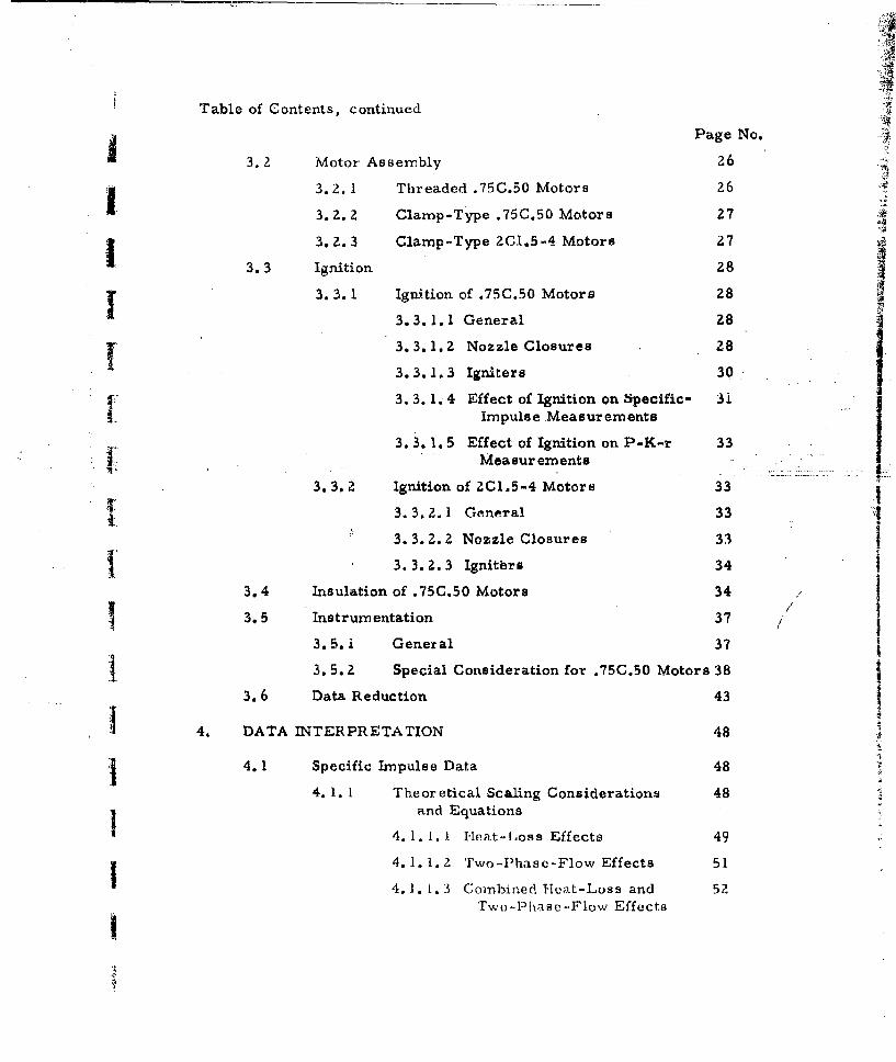
Table of Contents, continued
Page No.
3.2 Motor Assembly 26
1~3.2.1 Threaded .75C.50 Motors 26
3.2.2 Clamp-Type .75C.50 Motors 27
3.2.3 Clamp-Type 20I.5-4 Motors 27
3.3 Ignition 28
3. 3. 1 Ignition of .75C.50 Motors 28
3.3.1.1 General 28
3.3.1.2 Nozzle Closures 28 I..3.3.1.3 Igniters 30
3. 3. 1.4 Effect of Ignition on Specific- 3iImpulse Measurements
3. 3. 1. 5 Effect of Ignition on P-K-r 33• Measur ements
3.3.2 Ignition of ZCl.5-4 Motors 33•# 3. 3.2. 1. General 33-.i
3. 3. Z. 2 Nozzle Closures 33T3. 3. 2. 3 Ignitbrs 34
3.4 Insulation of .75C.50 Motors 34
3.5 Instrumentation 37
3.5. i General 37
j 3.5.2 Special Consideration for .75C.50 Motors 38
3.6 Data Reduction 43
S4. DATA INTERPRETATION 48
4. 1 Specific Impulse Data 48
4. 1. 1 Theoretical Scaling Considerations 48and Equations
4.1.1. 1 Heat-Loss Effects 49
4.1. 1.2 Two-Phase-Flow Effects 51
4.1. 1.3 Combined Heat-Loss and 52Two-Phasc-Flow EffectsI
J
Table of Contents, continued
Page No.
-1 4. 1. 2 Calculation of Fractional Velocity 54A Lag (A)
4. 1. 3 Determination of Scaling Factors 55
4. 1. 4 Prediction of Large-Motor Specific- 59Impulse
4.2 P-K-r and Temperature-Coefficient Data 59
BIBLIOGRAPHY 65
APPENDICES
SA. Data-Reduction Definitions and Procedures
B. Calculation of Velocity Lag in Two.-Phase Flow
f.. .... C. FORTRAN Program for the Calculation of Velocity Lag.... D. Velocity-Lag Curves for RH-P-l2i Propellant
E. Examples of Scaling-Factor Determination and. Specific-Impulse Prediction
F. Heat-Loss-Surface-Area Deterr- 4 1...tion
Ii
II

BALLISTIC EVALUATION OF PROPELLANTSSIN MICRO-MOTORS _
I. Introduction
j IOver the past several years there has been a general
trend in propellant research toward the use of smaller motors for ballistic-
I evaluation purposes. Many factors have contributed to this, including
(a) a large number of new contractors in the field of propellant research,
most of whom have an upper restriction on propellant quantity, (b) Increasing
toxicity and/or sensitivity of new formulations, and (c) limited availability
" "or excessive costs of novel propellant ingredients. These factors make
ballistic evaluation of propellants in small motors either highly desirable
or mandatory, and have caused many groups to revaluate their ideas
concerning motor size and ballistic measurements.
Early in 1960 the Redstone Arsenal Research Division of
Rohm & Haas Company initiated the development of a ten-gram microh.
4 motor for solid propellant static-test purposes. The resulting motor was
a small-scale model (.75-in. I. D. X 1.5-in. long) of the Division's standard
6C5-1l.4 test motor. Additional .75-in.-I. D. micro-motors in lengths
of 2.5 and 3.5 inches were subsequently developed. Static tests of several
j thousand micro-motors containing a variety of prxopellant formulations
demonstrated that reliable, precise ballistic data could be obtained if
proper experimental techniques were used.
Concurrent with the r icro-motor development, a parallel
investigation of the specific-inpulse scaling phenomena of solid propellants
was being conducted by this Division. An extensive series of static tests
showed that specific impulse could be scaled when corrections were made
for heat-loss and two-phase-flow effects. Specifically, it was found that
I experiment;d 1scaling factors relating to heat flux and condensed-phase
pirticlc dianwIter o01u)d btf (.xtracterl from dnata ohtained by static testing
F

-2-
a propellant in a series of small-motor configurations, that these scaling
factors could be used to accurately predict the specific impulse of the
propellant in any other untested motor configuration, and that these
scaling factors could be obtained from a series of micro-motor tests
requiring as little as two pounds of propellant,
I Most recently, the micro-motor hardware and casting
equipment were redesigned to allow completely remote operation, and
remote casting and firing facilities were designed and constructed. These
modifications allow evaluation of very hazardous materials.
IThis report is a summary of all previous reports on the
development of micro-motors and small-scale testing and is directedSi toward those groups who might wish to use the Rohm & H4aas mnicro-motor
system for propellant evaluation purposes. Accordingly, the areas of
system design featuruj, motor preparation and assembly, ignition, data
"acquisition, data reduclion, scaling effects, scaling-factor determination,
"I •and specific inpulse prediction harve been treated in considerable detail.
Sufficient information is provided to allow interested agencies to duplicate
i the hardware system, conduct static tests, obtain valid ballistic data
and scaling factors, and make specific-impulse predictions. Details of
j previous scaling data and prediction results for specific propellants may
be obtained from the material listed in the Bibliography.
E e. sign Features
- 2.1 General
'The standard Rohm & Haas motor designation used through-
j out this report is as ioliovws: reading from left to right, the first number
represents motor I. D. , the letter group designates grain design, the next
number represents grain I. D. , and the last nUmber represents motor
chamber length. As an illustration the .75C.50-1.5 motor has a case
S.D. of 0.75 in., a cylindric:al grain design, a grain I.D. of 00 in. , and
a motor case lergth of 1.') in.I!
-3-
2.2 Motors
Z.2.1 Thread-Type .75C.50 Motorx
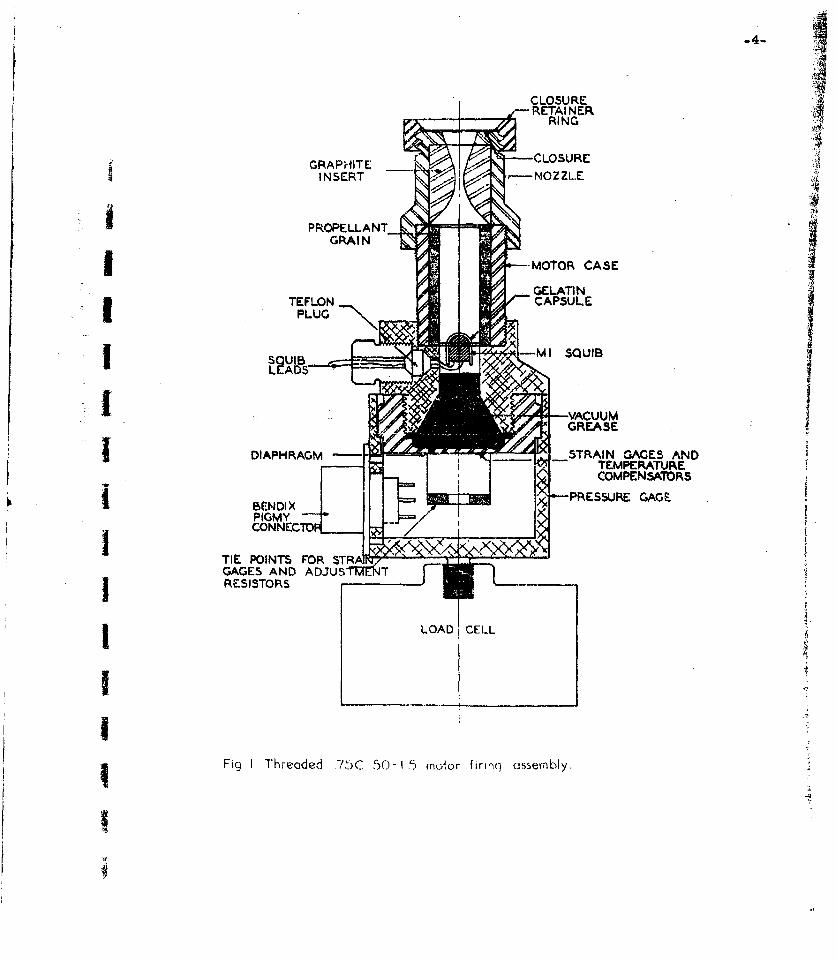
The threaded .75C.50 motor (Fig. 1) is attached to its
associated hardware with machine threads and was designed for non-remote
assembly. The motor bodiets are 1.000-in. 0. D. X 0.750-in. I.D. mild
steel tubes with 1-1/8 - 12 RF male threads on each end. The standard
motor lengths are 1.5, 2.5, and 3.5 in. The nozzle is mild steel with a
graphite insert and is threaded on the exit end for attachment of a nozzle.
17 closure retainer. The other end of the motor attaches to a special pressure
transducer and squib-lead sealing asseml6y which is in turn attached to
a load cell. Squib leads are sealed by a gland nut and Teflon packing.
Several motors may be connected together with threaded
couplings to obtain greater lengths. Threaded connections provide adequate
sealing for all joints in the motor system.
Motors have been hydrostatically tested to 13, 000 psiL
without failure, lndicating that a working pressure of 10, 000 psi can be
considered safe. However, an all-steel nozzle is required for pressures
about 6000 psi to prevent failure of the graphite insert.
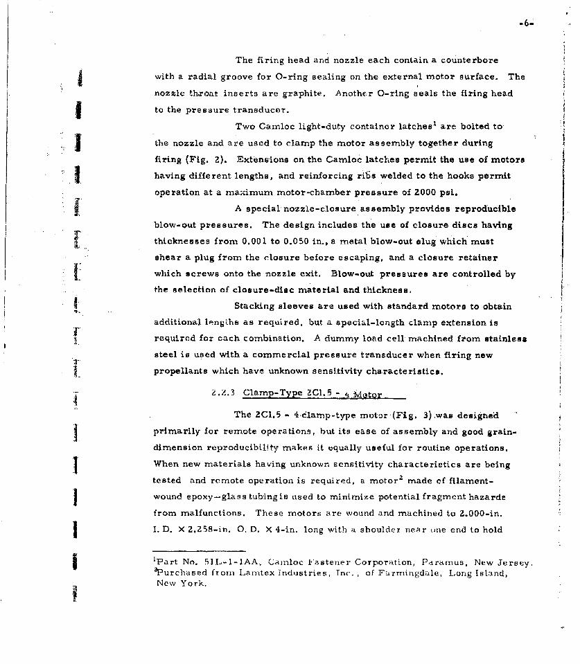
2.2.2 Clamp-Type .75C.50 Motor
The clamp type .75C.50 motor (Fig. 2) was designed for
remote casting, assembly, and firing but is also used for non-remote
operations. The motor is attached to its associated firing hardware with
cam-action containter latches. The motor dimensions are 0.750-in. I. D.
X 0.950-in. 0. D. with the same lengths as for the threaded motors.
Shoulders are machined on the outer surface near the motor ends to
facilitate casting-equipment disassembly. Motors are currently fabricated
from both stainless steel, and phenolic-g]ass-iber tubes.-
'-Detailed shop drawings of all hardware and components are available
upon request.ZThe glass-fiber motors were purchased from Dynetics, Inc., 34 Crestview
Road, Mountain Lakes, New Jersey.
-44CLOSU RERETAINER
RING
GRAPHITE CLOSUREINSERT ~-NOZ ZL.E.
I -MOTOR CASE
DIPHAM M I__ _SQUAIB AE N
TEMPERATURE
jCOMPSISTORS
PIM

.050 MAX THICK~NESS
CLOS5URE RETA1I'JER BLOvj-GUT DIV.RINJG
NOZZE -SPACER GASK~ET
CAMLOCIK LIGHT DUTY-ý0LATCH NO. 6IL-I-IAA
MOTOR CASEGRI
FAT
ENER EXT
ENSION
CAPSULE M QI
REINFORCED DRAW
FIRING HEAD/ IGNITER -
HOLDER VCUGREASE IGNITION PO0RIT
PARI4ER1'O"RING N0.2-2l, SCREW
Ik10xII'.0TEFLON4 COMPIRESSiONI1511151SUR! GLANDGAGE
LOAD CELL
Fir. Clomp-type .75C.50-3I.5 mofor firing assembly.
-6-
The firing head and nozzle each contain a counterbore
jwith a radial groove for O-ring sealing on the external motor surface. The
nozzle theroat inserts are graphite. Another O-ring seals the firing head
I to the pressure transducer.
Two Camloc light-duty container latches1 are bolted to A
the nozzle and are used to clamp the motor assembly together during
firing (Fig. 2). Extensions on the Camloc latches permit the use of motors
5having different lengths, and reinforcing riGs welded to the hooks permit
operation at a maximnum motor-chamber pressure of 2000 psi.
A special nozzle-closure assembly provides reproducible
blow-out pressures. The design includes the use of closure discs having
thicknesses from 0.001 to 0.050 in., a metal blow-out slug which must
shear a plug from the closure before escaping, and a closure retainer
which screws onto the nozzle exit, Blow-out pressures are controlled by
the selection of closure-disc material and thickness.
Stacking sleeves are used with standard motors to obtain
additional lengths as required, but a special-length clamp extension is
required for each combination. A dummy load cell machined from stainless
steel is used with a commercial pressure transducer when firing new
propellants which have unknown sensitivity characteristics.
Z.?.3 Clamp-Type ZC1.5 -_'Vagtor
The ZCI.5 - 4 -6.lamp-type motor (Fig. 3).was designed
primarily for remote operations, but its ease of assembly and good grain-
dimension reproducibility makes it equally useful for routine operations.
When new materials having unknown sensitivity characteristics are being
tested and remote operation is required, a motor 2 made of filament-
wound epoxy-glass tubing is used to minimize potential fragment hazarde
from malfunctions. These motors are wound and machined to 2.000-in.
I. D. X 2.Z58-in. 0. D. X 4-in. long with a shouldex near tine end to hold
S'Part No. 51L-I-IAA, Camloc Fastener Corporation, Pi-arnus, New Jersey.aPurchased from Larntex industries, Inc. , of F;rrmingdale, Long Island,
New York,

-7-
AA
-- SQUIB LEADS
j NOZZLE
NOZZLE RETAINING RING[-NOZZLE HOUSING
GRAPHITE INSERT p1-*O RING PACKING DASH NO.30,13/4 I.D. x 2 I/ O.D.
VO RING PACKER NO. 2-228,j NOZZLE 2 1/4 i.D x.1 '/.a WEB.
CLOSURE -CAMLOCK HOOK NO.A7L 15-IA
MOTOR BODY [--- PROPELLANT GRAIN
FASTENER EXTENSION
IGNITER CAMLOCK FASTENER NO.37L I1-1
-VACUUM GREASE
PRESSURE PORTSSI -- FIRING HEAD
LOAD CELL ADAPTER
"LOAD CELL
Fig•3 Clamp-type 2CI 5-e-. mrsnr firing assembly
• -8.-
the motor during casting-equipment disassembly. The outer surface of
the motor is used as an O-ring seal and casting-fixture-alignment surface.
For non-remote operation a motor made of 2.000-in.- I. D. stainless steel
I tubing having dimensions similar to those of the glass fiber motor may
be used.
I JThe firing head contains a counterbore with an 0-ring
groove for'inserting one end of the motor, two threaded ports for installing
commercial pressure transducers, a threaded boss for mounting to a
commercial load cell, and two Camloc heav-y-duty container latch1 assemblies
J for clamping the motor firing assembly together. Two mating Camloc
hooksa are welded to the nozzle housing which also contains a counterbore
with an O-ring groove for inserting the othe.r end of the motor. Both
firing head and nozzle housing are made of mild steel. Steel nozzle
inserts containing press-fitted graphite throats are seMed in the nozzle
housing with O-rings and are retained by a threaded steel ring.
¶ The Camloc latch as received from the manufacturer
will function at a maximum chamber pressure of 1700 psi, but the.Ur
maximum chamber pressure can be increased to 2000 psi by replacing
the latch shear pins with hardened steel bolts. Latch extension arms
I' serve as turnbuckles for adjusting the latch length and are fabricated in
length increments required for use with 4-in. , 8-in. , 12-in. , and 16-in.
motor combinations. All motors are cast in 4-in. lengths; the additional
lengths, which are used only for non-remote firings, are obtained by
Icoupling the motors end to end through the use of 0-ring-sealed short
sleeves which provide a 1/46-in. gap between motor sections. The use of
I turnbuckle-type extensions requires fabrication of latch lugs with left- hand
threads. Both the lugs and extensions are fabricated from Type 4130
steel and heat treated.
!'Carnloc Part No. 37LII-IB.2Canzloc Part No. 37LI5-IA.

A special firing head and nozzle housing, with the latch
1 assembly replaced by V/2 -in. steel tie rods, are used for non-remote
assembly of motors when charnber pressures from 2000 to 3000 psi are
1 ~ anticipated. A dummy load cell is used when firing novel propellants
which have unknown characteristics.
2.3 Remote Castirig Equipment and Facilities
2.3,1 .75C.50 Motor Casting Fixtures
Casting fixtures (Fig. 4) for both the threaded- and clamp-
type .75C.50 motors are assembled and disassembled using a screw-
-clamp fixture;. Two stationary yokes at the top of the cl..mp hold the
one-piece casting base and mandrel. Mandrel alignment is provided by
a Teflon gasket at the mandrel base, and by a spacer at the top, which
is inserted temporarily during ais'embiy and removed immediately prior
to casting. The clamp, with the screw manually driven by a hand crank
or remotely driven by a geared air motor, disassembles the motor and
casting fixtures. A Teflon plug fits into the upper end of a 0.5(U.,in.-O. D.
hollow mandrel during the filling operation. When filling is completed,
the plug is removed and a Teflon overfill plug is inserted which forces
the excess propellant into the hollow portion of the mandrel. The overfill i
j plug in conjunction with a gasket at the base of the mandrel provides a
/3a-in, grain recess at each end of the motor.
Z.3.2 ZCI.5-4 Motor Casting Fixtures
Casting fixtures for the 2C1,5 motor (Fig. 5) consist of
a casting head, a one-piece casting base and mandrel, a break-off
j ring, and two tie rods. Small wooden cross pins are used on the bottom
ends of the tie rods to act as shear pins during remote disassembly. A
shuulder on the base of the mandrel, and the break-away ring provide a
i/1 6 -in. grain recegs at each end of the motor. A remote casting-fixture
I disassembly device (Fig. 6) actuatted by a double-acting air-draulic
Ld
CL 00
-i -j
-'<- cc
ED R 0
0 a:
I-0 0
~0-0- 0
LUO
I E
L.9D
cr
sestAvaiableCOP

_"..•-BR EAK-A-WAY RING-- / CASTING HEAD
.-.-- WOOD SHEAR PIN
v-TIE ROD
I -- 2CL5 X4 IN. MOTOR
FIg.5 Casting equ!pment for 2CI.5-4 'motors.
cylinder is used to disassemble the motor. The casting fixture is
seton hejiginan invcrted position. As the moveable portion comesdown, two fingers press against the tie rods, removing them, the casting
I head, and the break-off ring. The puller jaw engages a button on the end
of the mandrel, and the mandrel is extracted on the upward stroke.
- 2.3.3 Remote Casting Facilities
Liaree facilities, differing primarily in size and propel-
lant-haidling capacities, were designed and constructed for mixing and
casting hazardous propellants. Two small facilities were built to handle
up to 250 g of propellant. Operations are carried out behind a semicircular
I steel shield (Figs. 7 and 8) having a radius of three feet with two AMF
Mini-Manip manipulators'; a rectangular Plexiglasa sight port provides
for direct viewing. The air within each shield may be maintained at a
dew point of -50 C, thus allowing the processing of hygroscopic materials.
'Part No. 89-63-R1000, AMY Atomics, A Division of American Machine &Foundry Company, 140 Greenwich Ave. , Greenwich, Conn.
ýRohrn & Ilaas Con-ipany, Philacielphia, Pennsylvania.
AIR DRAULIC CYLINDER4 1/2 BORE 5 IN STROKE
I
-1 0
i :
DASH NO.34÷U* RING
PACKING 2 1/4 ID1-- 2 5i8 O D TWO REVDt
7... .. .. .... . F L § ..... _ -
Fig 6 2C0.5-4 motior remote mondrel pullcr!

A:3
Fig.?7 250- gram remote casfing facilify-front view.
F7 a i~ -ra iw
'B s

-14-
One shield was designed for casting .75C.50 motors and the other was
designed for casting both .75C.50 and 2CI.5 motors.
The third facility (Figs. 9 and 10) was designed to
handle up to 2 lbs of propellant. Mixing, casting, curing, and motor
disassembly are carried out remotely in a concrete cell. Transfer
operations are handled with two AMF Model 8 extended-reach standard-
duty manipulators.while processing equipment is operated with compressed
air or hydraulically. A sight-port containing a 3-in. block of Plexiglas
is used for direct viewing, and close-up views of equipment and controls
are provided with a closed-circuit television camera.
F9c 9 Operoting control area for 2-lb. remote mixing and casting facility.
Best Available Copy

L-o5-
Ii ,1 -F c, p ()- ! ~ -ýr i e o( o il
IlbeCPIetA3
-16-
2.4 Remote Motor Ass~enbly and Firing Facility
The remote mnotor assembly and firing faciliLy was
designed for installation within an existing static-firing-range bunker.
SThe facility provides for completely remote assembly, firing, or
disassembly of .75C.50 and ZC1.5-4 clamp-type motors without personneli exposure.
A thrust plate for firing motors in a vertical position is
I mounted at table-top level on a reinforced concrete block. A 1-in. -thick
steel shield is set in front of the stand and a heavy wire-mesh screenextends from the top of the shield to the bunker ceiling to protect the
operator while the motor is being set on the firing stand. Transfer
operations within the test cell are handled with a Mini-Manip manipulator
which is set in the upper right-hand corner of the shield while mota's.
are prepaired for firing.' A' 14-in,.;wide X 22--in.-high opening is provided
in the shield for a movable Plexiglas sight-port which also serves as an
access door. The door ic air-powered and is remotely actuated.
Motors are brought to the stand for firing in an armoured
transporter. An air-cylinder-actuated retracting cup on the stand is
automatically actuated by door movements. When the door is opened,
the cup swings toward the door opening. The motor is transferred from
the transporter to the cup with a Mini-Manip on the transporter. The
i door is closed, and the cup and motor are retracted inside the shield.
Fig. 11 shows an outside view of the shieldwiththeldoor open and the
manipulator installed. With the shield door closed, the operator
assembles the motor remotely, removes-the manipulator, and leaves
the bay before the motor is fired.
The .75C.50-motor asEsembly and disassembly fixtures
use a pivoted motor-clamping yoke and a pivoted unlatching hook in
conjunction with the manipulator. Fixtures for the remote assembly and
disassembly of 2C1.5 - 4 rn.oturs are clamped and unclamped by ropes
extending through the front of the shield. Figs. 1Z and 13 illustrate some
steps in the assembly of .75C.50 and ZC1. claimnp-type motors,
TIPIH
PE
FiIi R m t ifc ts aiiy
,n AdbeCP
-18-
(A') GAUGES, FIRING HEAD (B) MOTOR INSERTED INTOANIGIERI LC FIRING HEAD
(c) NOZ-ZLE ASSEMBLY (D) COMPLETE ASSEMBLY,
I READY TO FIRE
Fig. 12 Stc~ps it) ýhe cs;serrbly of the .750.50 micro-motor for firing in the
Best Availlable COPY
(A) AUGE AN FIRNG B) MTOR ASEIN-1AC-
HEDI LC OZEBIGTAS
(A)GAUGZES ANDSFIRIN (D)CMoIoR CASSEMINBLACEHEAD IN PLACEENOZZLE BINTRANS
ýjsý--mby o th 2 i. FE4 R RED.ýý, iir n k
IialeCPIes Av 4l
-20-
The facility was tested by detonating 250 g of C-4
explosive confined in a 2Cl.5-4fiberglass motor located at the position of
normal motor firing. The sight-port withstood a separate test with
250 g of C-4 in a fiberglass motor located 3 -in. from the inside pane.
Zo5 Self-Propelled Hazardous Materials Carrier
IA powered vehicle (Fig. 14) capable of safely transporting
g 1 lb of hazardous material from the remote-casting facilities to the
remote-firing facility without exposure of personnel was designed,
fabricated, and tested. The design was patterned after a hazardous
material vehicle designed and built by the E. I. duPont de Nemours &
f Company, Inc. f The vehicle consists of a warehouse-type electric truck
chassisa upon which is mounted a 30-in. sphere made of 1.5-in. steel.
t The vehicle is operated from a shielded cab.
The sphere is equipped with hydraulically actuated
devices which open an inwardly 9wingig lid and eatAnd a cup into which
hazardous material is placed. Transfer operations are handled remotely
with a modified Mini-Manip manipulator, installed in the front of the cab.
The walls of the cab are 1 in. thick in front (the surface most directly
} exposed to the sphere) and In. thick on the sides and top. Aluminum
doors in the rear protect the operator from blast overpressure in the
j event of an explosion outside of the sphere.
2.6 .75C.50 Motor Shielded Transport Containers
STwo types of portable contaeArs are used to transport
.75C.50 motors: a thick-wall closed vessel, and an open-end pipe-section
I carrier (Figs. 15 and 16).
I
'Explosives Department, Repauno Development LaLbratory, Gibbstown,New Jersey.
2-Model No. RW-,1).I36, Automatic Transportation Company, Chicago,Illinois.

Best AvaH2l,,.; C>

3. Experimental Techniques
3.1 Motor Preparation and Physical Measurements
3.1.1 Steel Motor Cleaning
Steel motor cases are hydroblasted thoroughly, rinsed
with water to remove all grit, dipped in acetone to remove the water,
and quickly transferred to a trichloroethylene-vapor degreaser. After Iremaining in the degreaser for several minutes, the motors are removed,capped on each end with plastic cap-plugs, and stored at a temperature
of +140 F until required for use.
3.1.2 Fiberglass Motor Cleaning
Fiberglass motors are hydroblasted very lightly to
"remove the surface glaze. The remaining operations are the same as Ifor the steel motors, except that time in the degreaser is reduced to
t about 30 seconds.
4 a 4, Dx ,•O o. 1 THICKI
/.....STEEL INC
4 I 3 DIA jN'N o /ý
I -~-~ 7IL DR'LL THRU
LID
Fiq 1.5 LDetoi-ible sornrle conluiuner
-23-
-212.1 ANGLL
ý7 1
-xI ANGLE
A ~WELD-ALL >AROUND
'-WELD-BOTH SIDE SIDE 7IKPATC RIF, E 32 O LSTCsr'
S4j~ O.D WALL 4130 SEAMLESSSTEEL TUBING
cc--HANDLE
I,3N SCHEDULE 40 PIPE
-- i-D x 1-5 O.D. x2- LONG16 lB 4PLASTIC TUBE
FOAM4ED PLASTIC
Fig.16 Open-end micro-motor carrier.
-24-
3.1.3 Lining
The motor liner depends on the type of propellant to
be cast. For composite double-base plastisol propellants, the cases
are sprayed with an extremely thin film of Rohm & Haas PL-l liner
(Table I). Many experimental propellants will bond adequately
to the clean steel or fiberglass motor cases, and no liner is required.
Any liner must be thin and uniform to avoid errore in burning rate
g measurements, as well as efficiency losses associated with long tail-offs.
Table I
I Composition of PL-l Liner
Constituent % by Weight
Cellulose Acetate (Powdered)a 4.57Triphenyl Phosphate Flakes Z.88Santicizer M.-17b 1.74
Red Lead (Pb 3 0 4 ) .02
Tolylene Diisocyanate (Hylene TM) .23
9 Acetone Tolylene 46.39
Methyl Cellos olve Acetated 44.17
I aType 384, Tennessee Eastman Co., Kingsport, Tenn.bMonsanto Chemical Co., St. Louis, Mo,CE. I. duPont de Nemours Co., Wilmington, Del.dEthylene Glycol Monomethyl Ether Acetate, Union Carbide
Chemical Co., New York, N. Y.S3.1.4 Casting
While propellant charges for micro-motors could be
formed in a number of ways, all motors tested by this Division have been
loaded by casting the propellant directly into the motor case and curing
it in place.
Casting techniques vary widely depending on the specific
propellant composition. For example, compositions which are very fluid
n,,ty be cast cadily, while extre-mely viscous compositions present

-25-
Sspecial problems. Specific casting techniques are described in two series
of reports of this Division: Quarcerly Progress Reports on Chemical
and Propellant Processing, and Quarterly Progress Reports on ARPA
I Projects.
3.1.5 Motor Cleanup
A certain amount of motor cleanup is usually required
after the grain has been cast. All external motor surfaces, especially
j those which mate with the nozzle and head closure, must be thoroughly
cleaned. A solvent such as acetone is usually used for this purpose.
3.1.6 Grain Trimming and inspection
"The goal during casting is the production of a perfect,
cast-to-length grain. However, it is sometimes necessary to trim the
grain to remove end flaws. In this event the motor is clamped in a vise
and a small. 90' knife is used to trim the grain ends, using a special
Strimming jig as the knife guide. After trimming and cleaning, the motor
is visually inspected for propellant voids, cracks, case-bond failures or
p other irregularities.
3.1.7 Weighing
Motor cases are weighed after lining, before firing
(after trimming), and after firing. The .75C.50 motors are weighed on a
200-gram direct-reading Mettler electric analytical balance which can
be read to 0.1 milligram. The ZC1.5-4 motors are weighed on a similar800-gram Mettler balance which car, be read to 0.01 gram. Due to the
small size of the motors, weights must be determined with extreme
accuracy to provide accurate specific-impulse measurements. Conse-
quently, particular care must be taken to insure that the motor case
before and after firing is unaitered with the exception of propellant and
I liner consunmed.

-26-
3. 1.8 Grain and Nozzle Measurements
Grain length is measured to 0.01 inch with a standard
steel rule. Grain web thickness is measured to 0.001 inch from measure-
ments of the grain I. D. before firing and case I. D. after firing; the
motor is not cleaned before the latter measurement. Nozzle-throat
diameters are measured to 0.001 inch before firing, after firing on top
of any material deposited in the nozzle, and after removal of deposits
in the nozzle. Small expanding-ball-type hole gauges and standard
micrometers are used for throat-diameter measurements. Nozzle
SI exit diameter is measured to 0.001 inch using an inside-reading caliper
micrometer,
Extreme care must be taken to determine such physically
measured quantities as web thickness, nozzle throat and exit diameter,
j and charge weight, in order to obtain acceptFoble ballistic data. Due to
"the small magnitude of these quantities, allowable tolerances on mneasure-
I rments are inherently small and difficult to maintain.
3.2 Motor Assembly
3.2. 1 Threaded .75C.50 Motors
For threaded .75C.50 motors, the special pressure
gauge serves as the motor head-closure and contains the squib wire
pass-through port. The igniter is installed by passing the squib wires
down into the center of the gauge and out through the igniter port, threading
I the wires through the close-tolerance holes in the Teflon compression
gland, pulling the igniter well down to position it at the motor head end,
I and inserting and tightening the ignition port screw to provide the
pressure seal. A disc-type nozzle closure is installed at the nozzle
exit using a. closure-retaining ring which threads onto the nozzle aft end.
The pressure gauge and nozzle are threaded onto the ends of the motor
to complete the loading operations. A sectioned view of the load~d motor
iS shown in Fig. i.

-27-
3.2.2 Clamp-Type .75C.50 Motors
For the clamp-type .75C.50 motors, the igniter is
installed in the motor firing head in a manner completely analogous
to that used for igniter installation into the threaded motor pressure
gauge. The disc-type nozzle closure is similarly retained at the,
nozzle exit by a threaded retainer ring. Two types of nozzle-closure-
retainer ring assemblies are available: one clamps the closure to theij exit (as for the threaded motor), and one utilizes a coin-type slug to
rupture the closure, allowing better control of closure rupture pressure.
j1 The reinforced draw hooks are attached to the nozzle clamp arms (with
or without extensions, depending on motor length) and adjusted in length
j ifor proper assembly tension. Final assembly is made by inserting the
firing head into the special clamp-type pressure gauge, inserting one
j end of the motor into the firing head, pushing the nozzle down over thermotor end, placing tihe draw-hook feet under the rirn of the pros r.ure _gauge •
(clamp levers in a raised position), and seating the clamp levers. The
O-rinj;s and the outer-motor ends-should be lightly coated with a light
"vacuum grease and care must be taken not to pinch the nozzle and
firing-head O-rings during this operation. Since the pressure seal is
made by the O-rings on the motor case 0. D., clamp-arm tension is
not critical and need only be sufficient to provide a snug assembly. A
sectioned view of the assembled motor is shown in Fig. 2.
3.2.3 Clamp-Type 2C1.5-4 Motors
For the clamp-type ZG1.5..4 motors, the igniter and
closure are inetal]ed in the nozzle insert, which is then pushed into the
nozzle shell and secured by threading down the nozzle retaining hut.
The disc-type, bevelled closure is glued in the nozzle convergent section.
The squib-wire length is adjusted so that the igniter will be positioned at
the motor head-end when the motor is assembled. The outside eads of
the motor and the nozzle and firing-head O-rings are lightly coated with
-28-,
light vacuunm grease. Fins', assembly is made by inserting one end of
the motor into the firing head, piishing the nozzle housing down over the
motor end, placing the clamp lugs in the nozzle housing ears, and
seating the clamps. As for the clamp-type .75C.50 motors, clamp arm
tension is not critical and need only to be sufficient to provide a snug
- assembly. A section vie w of the assembled motor is shown in Fig. 3.
3.3 Ignitlon
3. 3. 1 Ignition of .75C.50 Motors
1 3.3. 1. 1 General
One of the major problem areas in the .75C.50 motor
I program has been the development of a satisfactory ignition system.
Many different types of ignition systems have been tested, utilizing a
variety of squibs, igniter materials, igniter weights, igniter positions,
nozzle closures, and clusure positions. Conclusions drawn as a result
I of these tests are summarized below.
3.3. 1.2 Nozzle Glosure;
A nozzle closure is essential to reduce ignition delay
I time and rise time, and to eliminate misfires and hangfires. For best
results, the closure should rupture at pressures between 80% and 120%16
of the motor equilibrium pressure. Nozzle closures placed in the nozzle
convergent section have usually caused severe ignition-pressure spikes;
much better results are obtained with a disc-type nozzle closure clamped
to the nozzle exit.
Disc-type nozzle closures should fail by shearing
cleanly at a diameter larger than the nozzle exit diameter. If the closure
does not shear cleanly rupture pressures will be variable and thrust
measurements will be affected by gas-flow disturbances produced by
protrusion of jagged edges of the closure into the exit gas stream. To
insure clean shearing of the nozzle closurer n qpnc~ial c]n•.uru.-retainer
-z -
is available which utilizes a coin-type slug to forcibly rupture the closure
j (Fig. 2). This assembly also provides much better precision of closure ý15
blowout pressure when metal closures are used.
Nominal nozzle-closure blowout pressures for regular
variable-diameter retainer rings are given in Table II and nominal
nozzle-closure blowout pressures for the special plug-type closure-
retainer assembly are given in Table III.
ITable I1
Nozzle-Closure Blowout Pressures for Regular Retainers
Closure Blo-wGut Pr_3uure a PsiaClosure Mat(-rial 0.625" Di,-teter 0.75" Dionivtc'r 0,875" lDiaTMatr 1.00" Dianaeterand 'rhickness Retainer Retainer Retainer Retainer
CA b-.0! MR 480 400 340 3002ICA -. 015" 700 590 500 440
CA -. 020" 92.0 780 670 580
CA -.0?rl" t 150 970 830 720
CA -. 030" 1380 1160 1000 870
i CA -. 035N 1620 1350 1160 1010
CA -. 040" 1850 1540 1320 1160
CA -. 045" 2080 1730 1490 1300
CA -. 0500 Z310 190 1650 1450CA -. 060" 2770 2310 1990 1730
|a
. .44t t.doito c200 p~ia.
C e S
Ai

-30- .
Table III
Nozzle-Closure Blowout Pressures for Plug-Type Assembly
Material Thickness, in Blowout Pressure, pu1a Ia., psia
Aluminuma 0.008 480 7
Aluminum 0.010 600 2
Aluminum 0.012 700 24
Aluminum 0.016 930 33
Aluminum 0.020 1170 34
Aluminum 0.025 1400 26
CAb 0.020 750 202
CA o.oz5 1060 139
CA 0.030 1360 115
CA 0.035 1540 247
Brass c 0.005 1060 60
a 1 0 0 - 0 aluminum sheet.bCellulose acetate sheet.CSheet shim stock.
3.3. 1.3 Igniters
The optimum igniter location is at the head end of the
motor with the squib wires passing through the firing head. If the igniter
is toward the aft end, the squib head may be torn from the squib wires
and plug the nozzle. rT;atisfactory ignition can usually be accomplished
with an igniter positioned in the nozzle expansion cone, but the necessary
piercing of the nozzle closure to permit squib-wire passage results in
ragged closure rupturing and erratic rupture pressures.
"-31-
F.>r propellants which are relatively easy to ignite, the
optimum igniter consists of an. M-1 squib for the 1.5-inch motor, or aIIsquib with additional RIP-1 or RHIm-I (Table IV) for the Z.5 and 3.5
inch long motors. The larger igniters are made by pouring the required
amount of igniter powder into the small half of a number 0 gelatin_ capsule,
SI inserting the squib into the capsule, and cernertlng the squib and capsule to-
gether with,Diicoacement. The resultant igniters are of the fast-acting, flash
itype. Table IV
Composition of RHmm-l Igniter Powder
Constituent Weight per cent fMetal Magnesium (55-I 00•) 60
KClO4 (-105i±) 25
Ba(NQ3 )2 (< 14.9ýLi) 15
For propellants which cannot be satisfactorily ignited
with the M-1 squib-RIlim-I system, a dipped Atlas Match igniter is
generally satisfactory. This igniter cons.sts of a plain Atlas Match
i squib which is repeatedly dipped into a slurry of RHim-1 and a solution
of 51o poly(isobutylene) in n-hexane until a sufficient quantity of the mnixturs
j adheres to the squib head. The solution is then allowed to evaporate,
leaving a coating of RHi•,n-l on the squib head. The resultant igniters|Uare of the soft, slow-burning type, and eject burning particles.
3. 3. 1. 4 Effect of Measurements
Corrected specif'ic impulse using the .75C.50 motors is 4
markedly depetudent upon ignition delay time, ignition woight, and ignition
rise time. Long ignition-delay times invariably result in low values of
'RIP-1 is a Picatinny Arsenal product consisting of 68.2% barium nitrate .and 31.8% magnesium.
" 1E, . DuPt'nt de Nr'rnwm,.; &t C.•., Wilringnton, Delaware.
-32-
specific impulse duo to propellant cook-off and increased heat losses.
On the other hand, the measured specific impulse will be too high if a
relatively large weight of igniter material is used, and no correction is
made for the contribution of the igniter. Measurements of specific impulse
of a typical plastisol propellant as a function of ignition delay time and
igniter weights demonstrated the need for short ignition-delay times with
minimum quantities of igniter. material (Fig. 17).
j The policy of this Division has been to use igniters which
weigh no more than onee-half per cent of the charge weight, and to make no
I igniter correction to specific impulse although the igniter adds about '/%to total impulse. This increase is very closely matched by an apparent
I decrease in impulse due to the fact that motors are fired vertically and
the loss of weight results in a base-line shift of the thrust cell. The M-1
i squib used to ignite the 1.5-inch motor contains about 50 milligrams of
combustible material, which is one-half per cent of the nominal charge
I weight. :."r 2.5- and 3.5-inch motors, RHim-l igniter powder is added toiImake the total igniter weight, including the M-1 squib weight, equal one-
half per cent of the charge weight.
LEGEND
0--0.4 9m. IGNITERS 250- b -0.2 gin. IGNI'T.R
0 0-0.1 qm. IGNITER-0 -005 gin. IGNITER•0.4 gm ..
S 240 "-._
9M 0
1 220-- J1 L L200 40o 600 800 1000 1200 1400 1600
IGNITION DELAY TIME m9PC
Fig 17 Effeci of ignition deiny ond !qniter ,vethllc- specific imiputse1r-easul ed in- ih 75C 50C micro ffolcor
-33-
If the weight of the igniter necessary to achieve ignition
is greater than one-half per cent of the charge weight, an igniter correction
should be applied to the measured specific impulse. The method used is
discussed in Section 3.6.
3.3. 1.5 Effect of Ignition on P-K-r Measurements
Ignition requirements for P-K-r measurements differ
SI somewhat from those for specific-impulse measurements. The primary
* objective is a pressure trace in which thW pressure builds up rapidly, end-
SI of-burning is sharp, and pressure decays rapidly. To obtain this, an
M-1 squib with additional RIUn-powder is used. Since the igniter-correction
problem which must be considered in specificdmpulse measurements is
not critical for P-K-r measurements, any amount of additional RHim-1 required
may be used to achieve the desired trace shape. In most cases . 05 to
.15 grams of RHim-1 is sufficient for ignition of the 1.5-inch motor. Clean
shearing of nozzle closures is not critical.
3. 3.2 Ignition of 2C1.5-4 Motors
3.3. 2. 1 General
I Two-inch-diameter motors are easier to ignltd than the
.75 -inch because as much as 0.7 gram ('A% of the charge weight) of
igniter material can be used for specific-impulse measurements. Larger
igniters may be used for P-K..r measurements.
I 3. 3. 2. 2 Nozzle Closures
Closures which rupture at pressures from 20 to 100 per cent
* of motor operating pressure are generally acceptable for 2-inch motors.
Plastic nozzle closures are usually cemnented into the nozzle converge:.xt
section with an adhesive such as Pliobond*'. An injection-molding process
is used to fabricate these closures (Fig. 18) in three diameters and a wide
range of thicknesses. Closures having a thickness between 0.035 and
0.060 inch generally provide excellent ignition for firings at a nominal
pressure of 1000 psia.
1 l'JhtG .".:odvw-;)r Tire & Rubb Gor C'. Akrun 16, Ohio.
-34-
10-I 10-2 10-3
• j Fig,18 Nozzle closures for 2C1.5-4 motors,
1 3.3. 2.3 igniters
Two types of igniters have been used for Z-inch motors:
I a fast-acting bag type and a slow-burning jelly-roll type. Both utilize
the Atlas Match squib.
I The bag-type igniter is made by enclosing the igniter
powder (either RIP or RHim) and the Atlas Match squib head in a 2-mil
polyethylene bag. The bag, cut from sheet stock, is fastened around the Isquib wires with a rubber band.
I The jelly-roll igniter is made by rolling up a narrow
rectangular strip of the previously prepared jelly-roll material aroundI ~the squib head; this is then wrapped tightly with one layer of 2-rail poly-
ethylene and secured with rubber bands. The finished product resembles
a jelly-roll, with the squib head in the center. The jelly-roll material
is prepared by coating a sheet of cheesecloth to a depth of about '/16-inchwith a slurry of RHi-n-I and a solution of 5% poly(isobutylene) in n-hexane,
3.4 Insulation of .75C.50 Motors
Quite accurate P-K-r and temperature-coefficient data
j *may be obtained from .75t7,.50 motors if the propellant temperature is
accurately known. However, because of their small mass, these motors
I can undergo rapid tr-.mperaturo changes. Consequently, if firing temperatures
other than ambient arc requircd, the. mnLors must be well-inmf1l;itcd to prevent

-35-
prohibitive propellant-temperature changes from occurring during the
time interval between removal fr om the c onditioning box and firing.
Temperature measurements were made by inserting a thermocouple in
the propellant of a .75C.50-1.5 motor. The motor was cooled to -40:'F
and removed from the cold box. After four minutes, the average time
from box to firing, the temperature had risen 401F with an initial
temperature differential of 125"F.(Fig. 19).• IVery good temperature control was achieved by insulating
the loaded-motor assembly, including the pressure gauge, in a close-
fitting rectangular box made of 1 -inch-thick polystyrene foam (Fig. 20).'
The box is open on the pressure gauge end, and is closed on the nozzle
end. The insulating box is left in place during firing, and upon ignition
a press-fit plug is blown out of the closed end of the box.
I I0I!S
80O0
7 70 I
80INE - IN TRATPRT ONIESso-1
30-INSULATED -NTIN TRANSPORT CONTAINERS
2 4 a 8 10 12 14 16 lB 20 22 24
T1ME -min.
Fig 0 Chanqe in propellant temperature in 75C.5-1.5 micro-moaors uj afurchton of time after removal from o cold box (t -40°F.
-36-
FRg.20 Insulating box for- .75C.50-1.5 motor. Assembled bo,, and motorat left. Cutaway view at center and right.
The complete insulated assembly is conditioned at the
required temperature. Several of these assemblies are then placed in
a larger insulated box, which has also been conditioned to the motor
temperature, for transportation to the firing range. The insulated motor
assemblies are removed one at a time for firing; a firing can usually
be accomplished within two minutes of removal from the insulated trans-
port box.
Temperature -time measurements made with a thermocouple
embedded in the propellant showed that the insulation reduced heat trwisfer
sufficiently that accurate estimates of the propellant temperature at the
time of firing could be made (Fig. 19).
Micro-motors have been successfully fired at extreme
temperatures of -40*F and +140*F. Since the pressure gauges are con-
ditioned with the motors they must be calibrated at these tem peatur es.
Best Availabfea Copy

-37-
S:ince the standard Gelvacenel light vacuum grease used to pack the gauges
is satisfactory at +140*F but freezes at -401F, Dow-Corning High-Vacuum
Grease dilu.ted with Dow Silicone Oil is used at -40*F.G
To prevent gas leaks from occurring on cold shots utilizing
the threaded-motor design, motors are assembled after thiý individual--.
components have been cooled. The clamp-type motors may be assembled4
at ambient temperaLurij.
I .s.5 Instrumentation
1 3.5. 1 General
The basic instrumentation system used for both .75C.50
I and 2Cl.5-4 motors is shown schematically in Fig. 21. The thrust channel
consists of a dual-thrust gauge, filter, calibrator, amplifier, and an analog
* and digital recording system. The pressure channel is basically the same
as the thrust channel exLept that a filter is not us~ed.a
3 ANALOG RECORDING
THRUSTR CAIBALTORAFITER AMPLIFIER SSEGAUGE
DAGIALO RECORDINGSYSTEM
Fig 21 ahus nd prusziure inshrurneniation used wiflh rnicro-motorbs.
'Consolidatvd Electrodynamnics Corporation, Pasadena, Californ~ia.

-38-
The amplifiers used are Kintel Model 112 1which have
the desirable characteristics for transient rneasurements of a wide
frequency response and a wide linear output-voltage range. A wide
frequency response is not in itself necessary but, unless the cutoff frequency
of the amplifier is considerably above the cutoff frequency of the filter, it
I is nccess,.ry that'the amplifier have the characteristics of a true filter. For
example,'amplifiers characterized by a slewing rate must be used with caution.
I Probably the best types of integrating systems for
transient data are those based upon the voltage-to-frequency type
I converter such as the Dyrnec Model 2211B.1 These converters have
excellent frequency response, wide linear overrange capacity, and a
full-scale frequency which is high enough to provide adequate resolution
for shots having a duration of I0 milliseconds or longer.
1 3. 5. 2 Special Considerations for .75C.50 Motors
I- In order to rninirnize the weight of the overall assembly,
a. special pressure gauge (Figs. 1 and 2) was designed for use with..75Ci0
motors. This pressure gauge is the same basic design as the Rohm & Haas
diaphragm gauge used by this Division for a number of years; the sensitive
element of the gauge is a diaphragm to which the strain-gauge bridge and
the temperature-compensating resistor are cemented. The gauge internal
cav~ty is fillcd with Celvacene light vacuum grease to protect the diaphragm,•1 reduce the motor free volume, and reduce motor heat losses. The resonant
p frequency of the assembly using a 50-pound load cell is approximately
130 cycles/sec.
The motor, pressure gauge, and thrust gauge constitute
a highly under-damped second-order system which is shocked into
i appreciable oscillation by the motor thrust. This oscillation is of such
magnitude that it interfercis with the digital integration by causing the
thrust. g-.uge output to swing below zero. To eliminate this oscill-i.ion,
a 50-cycle low-pass filter (Fig. 22) is included in the thrust.gauge circuit.
'Tohn Electrornics Inc. , IKintei Div. , San Diego, California.2 DTniec Div., _Hewlett-Packard Go., Pal]o Ato, Galifornia.

-39-
5H 6.8K
2MFD .5MFDCT-
Fig.22 Low-pass filter to eliminate thrust oscillation during .75C.50
I motor firings
II"I I
"The filter is designed according to the Butterworth' condition except
that R is adjusted for optimum transient response.
The attenuation of the filter above the cutoff frequency
increases at a rate of nearly 18 decibels/octave, but the oscillations
I are not sufficient]y attenuated when a 50-pound thrust gauge is used.
To provide more attenuation the capacitor C was added to form a trap forI the resonant freqluency of the system, approximately 130 cycrles. With
this addition the recorded traces are oscillationr.free.
ITbh total impulse of a motor is defined as f Elt)dt. In
practice, however, it is not F(t) that is integrated but a function, using
Laplace notation
I L "A(s)B(s)F(s)
'Ernst A. Guillemnin, ISynthesis of Passive Nctworlks, 0 John Wiley &Sonis, New York, 1957.
where F(s) LF(t), A(s) is the transform of the electronics of the system
and B(s) is the transform of the thrust stand and thrust gauge. If the
measured impulse is to be valid f L-IA(s)B(s)F(s)dt must equal f F(t)dt
even though L A(s)B(s)F(s) only approximates F(t), due to the transient
nature of the thrust, the rel.tively low frequency of the thrust stand,
and the filter.IThe method used to study this problem was to assume
as the thrust function F(t). the pulse I(t) - g(t-a), that is, a square
pulse of unit amplitude and a duration, which has a very Wide frequency
spectrum and to evaluate f L A(s)B(.s)F(s) by integration. The frequency
response of the amplifier and the digital system is very high (10,000 cycles),
and -the only frequency-dependenL component of A(s) that matters is the filter.
Let A(s) PG(s) where G(s) is a general low-pass filter
A• a + A s + ... +I5m IT)-I
in Rn-1B sn +B an' +...1 +1~jI n n-1
If B(s), the transform of the thrust stand, is ignored,and since
i1 1 e-as (IL[u(t) - u(t-a)] - - - a (
then
I A s + A s + +1LA(s)F(s) = (I - e • P (2)B fl n-I
B sn+B s + In n-i
By the theory of partial fractions the right hand side of Eq. 2 may be
expanded into
-as) ('+B1 + B Es + .DI +! W(8TW
-41-
The first term of the above expression -(I - c's) ir LF(t). Therefore if
fi' 1 -B)[ABs +C Es +D ~I - (I -e-L) + C Es-+ Dt.0
1 (3)
then
F = JdtA(s)F(s)dt (4)
(t00 0
I That Eq. 3 does equal zero may be shown by direct integration although.1 -O.j
this is not necessary since,by the Second Shifting Theorem,L e *(s) =
1 *(t-a)u(t-a), and each term of the inverse transform of Eq. 3 will contain
a minus exponential, so the Integral is obviously zero.
The an•lysis could be extended to a general ---(t) by
dividing F(t) into a succession of pulses Fi[u(t-Li) - u(t-LI.-a)] ardx then
letting a - 0.
I lettigar equtioSince the thrust stand is a second-order system with the
I familiar equation
m; + px +kx =F(t) (5)
its transform B(s) is
Bma& + p + k
which is mathematically the transform of a second-degree filter.
j Therefore the effect of the thrust stand may be included simply by adding
another term to Eq. 2 and the result is the same. Constants are
Sautomiatically taken care of by the calibration procedure.

-42-
These results mean that it is possible to integrate very
transient forcing functions using the same instrumentation that is used
for larger motors.
To demonstrate the mathemalical analysis experimentally,
a series of .75C.50-1.5 micro-motors was fired at various thrust/mass
ratios using a 100-pound load cell and various ddgtees'of filtering. The precision'_
of the measurements was not good, partly because the severe oscillations aexceeded the range of the load cell. However, fFdt seemed to be in-
dependent of the thrust/mass ratio and filtering (Table V).
Table V
Summary of Filter Check Data
No. Thrust/MassbRounds Batch Ratio Filter F%0 0 a
5 A 10 50 cycle 234.8
5 A 0.5 15 cycle 233,2
6 B 10 50 cycle 236.0 1-
5 B 10 None 235,3
43 0.5I cycle 235.5
SaSee Appentlix A for definition of ballistic parameters.
Thrust/mass ratios of 0.5 were achieved by adding 50 lbsmass to the standard motor; the standard configurationhad a thrust/mass ratio of 10.!I
In general, the accuracy of the measurements (as
distinct from the problem of motor reproducibility) should be esspntially
the same as with larger motors, An advantage is the ease with which
low-range gauges can be calibrated with dead weights. Occasionally,
Ssome of the 50- arcl .00-pound thrust gauges have gi.ven trouble because
of calibration instability. It is necessary to load the thrust gauges very
cunferva.tiv.ly ni.iic the high oscillatioil- level can over -range the galuge.
-43-
Generally the capacity of the thrust gauge should be at least twice the
maximum thrust expected.
Data from three ten-motor groups of .75C.50-3.5
rmicro-motors containing RH-P- I12cb propellant are shown in Table VI
to illustrate the precision of specific-impulse measurement which can
I be obtained when proper experimental techniques are used.
Table VI
Specific-_mpulsa Data from .75C.50-3.5 Micro-Motors
Average 1
Group No. Group Size FO___0 (absolute) (per cent)
1 10 241.0 1.0 0.4
[2 10 241.3 0.9 0.4
3 10 .40.0 0.4 0.2
1 3.6 Data Redw-Aion
Except for somewhat different definitions of parameters, data-
I' reduction methods for micro-motors are the same as those for large
motors. Conventional data-reduction procedures used by this Division,
as well as the exceptions required for micru-motors, are given in
Appendix A.SBecause ignition of micro-motors is uo critical, -.t is
possible to nbtain forms of pressure-time traces which deviate considerably
from those of larger motors. Application of conventional data-reduction
techniques to pressure traces can result in large errors. Several
j exaggerated forms of pressure-time traces which might be obtained
with micro-motors are given in Appendix A.
TI'he lower trace in Fig. 23 provides an example of how
erroneous data rnght be obtained using conventional data-reduction techniques. Tho i
conventional definition of start of action time and burning time is the time
at which pressure has risen to 100 psia on the primary rise portion of -41
the trace (point 3). This is not valid for the trace shown, since the pressure
-44-
I;/
I
I ---
I Fig, 23 Desired "square trace" (top) and on unusual pressure trace (bottom).
I. I
II
up to point 4 is caused by the igniter alone. Propellant begins to burn
at point 4, and this should be used as the start of burning time. If
beginning of action time is defined as the time at which the thrust trace
begins to rise, this should correspond to point 5 (the time at which the
closure ruptures). TJ e of the 100-psia convention would yield unrealistically
long values for burning time and action time, and correspoiadingly low
values for rb, Pb' and P. Values of F10 00 would be too high, since thelow value of P would be used] in the C equation employed in the
a Testcorrection.
-.45.-
Ishown in 1i.2;i nul onsar vial rmidvda
Igood traces. Poor traces are then discarded if enough, odtae are
available. However, when only a few mnotors; are available, all may
I produce irregular pressure traces. In this case the data would be re-
duer-d using procedures outlined in Appendix A.
I Any correction for excessive igniter contribution should
be made once F?000 is determined by the procedures outlined in Appenditx A.
Defining a new term (Ffoo) as the igniter -corrected )?Go the following
equations may be derived:
W.
!owo)j F00 - 'sI X (for correction to zero igniter weight)SBiAiwp (6)
0[) (F/ 0051r eiht(F?0 00 ) W F -~o .I 1 0.0 (for correction to 1/7%intr egt
B. p'i (7)
where I Bi specific- impulse of igni~ter (I Bp r, 110 for M-1 squlb and
pi RIP or RHim) 1
w weight of combustible material of igniter
4w =weight of propellant
Measurement of igniter specific Impulse by firin~g igniters
I in motors containing dumnmy grains andl measuring f Fdt1 is not practical
for micro-motors since the f Fdt of 0.05 grams of igiidter mate:ial'ist
not measurable on a 50-1b load cell. Consequently, igniter impulse was
determined by firing multiple roundFs with various amounts of igniter.
I The resulting plot of FOO0 0 versus igniter weight (Fig. Z4) was extrapolated
to zero igniter weight, yielding (FQD0 ) C The specific irxulse of the
igniter was then deduced by comparing (Fhou). wit1 lF6 0 0 for a particular
igniter weight.
'JANAY Solid Propellant Rockel. Stall.: Test Pa, el, ýRct:ornrncndud ProcedurcoI ~~for the Measitrement. Of Spec~ifiC Impulse of Sol~d Pptat, SPIA
Publication No, SiPSfl/1 OP M-ircb I 962.
-46-
R5
S ~236-•
"• 236 K il- - -[
I 234I.I.- - -"
24 -- NOTES:
i EACH POINT IS A FIVE-ROUND AVERAGE
2. BAR HEIGHT DENOTES RANGE OF F0,
1 232- FOR THE FIVE ROUNDS
S230o.I 0.2 0.3
IGNITER WEIGHT - gin.
Fi9. 2 4 Specific impulse as a function of igniter weight.
The standard micro-motor grain length is 3./ inch
shorter than the case. Occasionally, however, shorter grains will be
encountered, either because insufficient propellant was available to fill.
the motor or because the cured grains were trimmed to remove endI flaws. Since short grains will expose more of the motor case, heat
losses will be higher and specific impulse correspondingly lower. It
I is generally desirable to correct specific impulse for the additional
heat loss, giving a specific impulse which would have been measured
with a standard grain. This correction may be accomplished by use
of the following equation, which was derived from equations given in
Section 4 of this report.
•q zA t A A;---0 14-g (8) ,
F144 (actual nominalJ
-47-
where (F0ooo)= Fo0oo which should be obtained with standard length grain
J energy conversion factor, 778.16 ft-lbf/Btu
q - heat flux, Btu/sec-ftz
go = mass conversion factor = 32.174 ft-lbmn/lbf-secz
= = theoretical thermal efficiency
t = time interval during which heat is lost from propellanti c gases to motor hardware, sec
A = exposed motor hardware surface area, in-
m = propellant weight, Ibm
I Data-reduction practices used to obtain P-K-r data frommicro-motors are the same as those used throughout the industry, ifa regular trace is obtained. For the more peculiar traces, the procedures
outlined in Appendix A for micro-motors should be used to obtain
"" I rb andPeq" Kdata. IDue to the snmall web thickness (1/8 inch) of .75C.50 motors,
I small d€imensional variations along the grain have a pronQunced effect
on the apparent burning rate. Any variations present usually cause theIpropellant to burn out unevenly, resulting in lower-than-normal integral
ratios (f Pbdt/f Ptotdt as defined in Appendix A). In general, the lower
I the integral ratio the higher the apparent burning rate. Therefore, for
burning-rate measurements, no trace is considered whose integral ratio
is not at least 0.90, and for the most accurate rates, integral ratios of
0.95 or higher are preferred.
Data reduction for temperature-coefficient firings ishandled in the same way as for P-K-r data. The propellant temperature
I upon firing is estimated from experimental curves such as those in
Fig. 2 1.
-48-
Teinperature coefficient of pressure at constant K, rz,
is calculated as follows:
Pa -P100Ir =x o (9)
whr K (Pz+ PA) TZ - T,
where P1 = average pressure over burning time at temperature T1.
i P2 = average pressure over burning time at temperature Tp.
4 Data Interpretation
1 4. 1 Specific-Impulse Data
Strict compliance with all the methods and techniques
described in Section 2 of this report will yield numbers which can properly
be called Fo 0 in the (.75C.50-1.5, .75C.50-2.5, .75C.50-3.5, ZC1.5-4)micro-motor. These numbers in themnselves have no particular significance
unless they form the basis for a predicted specific impulse for the specific
composition in a much larger motor which has a specific application.
j 4. 1. 1 Theoretical Scaling Considerations and Equations
TFeoretically, the corrected specific impulse of a motor-
propellant systemn is dependent upon the following factors:
(a) the basic available combustion energy of the propellant;
I (b) the amount of energy lost from the propellant gases in the form ofheat transfer to the motor components;
I (c) the degree of kinetic and thermal equilibrium attained between thegaseous and condensed phases of the combustion products during theexpansion process;
(d) combustion efficiency, or the relative completeness of combustionachieved in the motor chamber; and
(e) the degree of dissociation and/or recombination of the productgascs during the expansion process.
-49-
Items (b) through (e) can be expected to vary with motor size and con-
figuration, and these variations are responsible for the frequently
observed specific -impulse scaling effect, or the difference in FTO00
between motors of different sizes containing identical propellants.
4.1.1. 1 Heat-Loss Effects
Assuming complete Idnetic and thermal equilibrium
between gaseous and condensed combustion products, the specific impulse
equation may be written as
FaoV'0 (F H) ) -'3(H1-H) (10)
SwhereT = energy conversion factor, 778.16ft-lbf/Btu
go a mass conversion factor, 32.174 ft-lbm/lbf-s.e3 Il4H - isentropic enthalpy change of combustion pruducts during
expanoion through the riozzlc, Btu/lbm
Il = enthalpy of combustion products at nozzle entrance, Btu/lbmI - != enthalpy of combustion products at nozzle exit, Btu/jbm
From the relation
411 =CpT (11)
S' 0 may be rewritten as-, Ipr ! , .X -z
g0 0 V/ C1pcTc I e 6 (12)
where
= specific heat at constant pressure of the combustion products(in the chamber) at temperature Tc, Btu/lbm-fIR.
C specific heat at constant pressure of the combustion productsI e (at the nozzle exit) at temperature Tc Btu/1bm-°R
T n chamber temp,:rature, 'RC
T =exit temnperature, 'Re C
H = C *ISC PC T C
-50-
Assuming thnat heat i s lost from the combustion gases in
the form of heat transfer to the combustion chamber, and that the chamber
enthalpy would have been H instead of H had the heat loss not occurred,o c
the heat loss may be expressed as
0/~l- C TO0 C T -3
where Q/m = heat lost from combustion products to the motor chamber,Btu/lbm
H 0= enthalpy of combustion products in the chamber for thecase of no heat loss, Btu/lbm
C = specific heat at constant pressure of the combustionP0o products at temperature T0 , Btu/lbm-*R IT = chamber temperature for the case of no heat loss, 'R.
Substitution of Eq. 13 into Eq. 12 yields
go/m (14)
The specific impulse that would have been obtained for
the case of no heat loss may be expressed as
10 T11 ýLg. I-HLo
00
where C' = specific heat at constant pressure of the exit products atPe temperature Tt., Btu/lbrn-'R
AT-I0 isentropic enthalpy change of the combustion products duringexpansion through the nozzle for the case. of no heat loss, BLu/lbrn
TI1' enthalpy of combustion products at nozzle exI.t for the case ofC no heat loss, Btu/lbm
'P" = exit te mperature for the case of no heat loss, *I<.- C1 T'
c; T()j ( )

-51 -
Since i t-n, Eq. 15 may be substituted into Eq. 14
to yield
F 1 L 0 Zn m Q
Eq. 16 relates the specific impulse actually obtained 4when heat loss occurred (F?0), the specific impulse which would have
been obtained had heat loss not occurred (.I0L) and the amount of heat
lost (Q/m).
4. 1. 1. Z Two-Phase-Flow Effects
The specific impulse equation may be written as
3 v + in VnV YV + Xv1 0 0 0 = =s g9 +mi + 9 0 ( i n + s ( 1 7 )= "(T +! 1) = gO
Ifor a two-phase system, where
mass flow rate of gaseous phase at nozzle ekit, Ibm/secgn = mass flow rate of condensed phase at nozzle exit, lbm/bu
V 9= velocity of gaseous phase at nozzle exit, ft/sec
V = velocity of condensed phase at nozzle exit, ft/sec
T
if V =V (no velocity lag of the condensed phase), :
g g
Eq. 17 reduces to Vf
VL V 9:• VL o :'0
-52 -
Dividing Eq. 17 by Eq. 18 results in
U 0 V 8xV V (19) S= 8= y (i
'VV Vg g
The fractional velocity lag may be defined asidA V -V V
g g(20)
Substitution of Eq. 20 into Eq. 19 yields
0|= y+x(l -A) = y+x-xA = , -X& (Z 1)
Vil
Eq. 21 relates the specific impulse. actually obtained
whon velority lag of the cor densed phase occurs (FOO), the specific impulse
which would have beern obtaltied had no velocity lag oaurred ( the weight
fraction o'f ondensed products (x), and the fractional velocity lag of the con-
densed products (A).
4' I. 1.3 Combined Heat Loss and Two-Phase Flow Efiects
Eq. Z I may be writtfn in the form
- --xA (22)
where l specific impulse which should be obtained if velocity lagwr HL occurs but heat loss dpoe not occur
I0 -- specific impulse which should be obtained if neither heatloss nor velocity lag occurs.
Substitution of Eq. 2Z into Eq. 16 yields
FO 00 I0)z (I ×XA)a- Z3 Qg0 rn
-53-
The unknown quantity fo may be eliminated by writing Eq. Z3 for two
static test motors and solving the resulting equations simultaneously as
follows:
(F, 0 0 ), = (' o) (1 ( x&,)' - z i (Q/m h (24) 4
• '-- ( Q/ r n) 1 - ' () i)
I • The heat-loss term, Q, in Eq. 26 may be expressed asj qt A
(7
(F O 4" (I'D?(l x&" (25)1440
•..[where q = heat flux, Btu/sec-ft2 It time interval during which heat is lost to internal motortz hardware (motor action tirne), sec 4
A M urface area of InternMl motor hardware to which heat a•
F100 last, tn2 0
Substitution of Eq. 27 into Eq. 26 yields e
qt ',A 27
144 0
ie t E. 8 relates the specific impulses of two arbitrary imotors (containing identical propellants) in terms of their
rcapective velocity lags and heat losses, and is the basic equation used !by this Divisior to predict large-motor specific impulse and to determinescaling factors from smalrl- rnotor static-test data,hea
is lot, .n
Subsituton f Eq Z7intoEq.26 yeld
I X Z~ l q __ q ý (2
(F I0 0)z- -(F 01 00 2 14 go m 144 go
-4
-54-
Eq. 28 is riot a rigorous equation; many simplifying
assumptions were made in its derivation. However, it has proven to
be valuable and useful in its present form, and consequently no attempts
have been made to perform a more rigorous analysis.
4. 1. 2 Calculation of Fractional Velocity Lag (A)
I A FORTRAN computer program developed at this Division
is currently used to calculate fractional velocity lag (A). A simplified
mathematical model is used to approximate the real flow process. This
simplified model, which ignores the coupled effect of the particle lag
" •on the flow of the gas phase, permits rapid estimation of the effects of
solid particles and nozzle configuration on performance. The -model is
not sophisticated; however, it has been satisfactory for the determination
of specific-impulse scaling -factors from small-motor static tests.
I Description of the program and the mathematical model is given in
SAppendix B3 and a complete listing of the FORTRAN program is given Iin Appendix C.
B~efore the prosent program was developed, an even more
P 1 simplified version prograrmed for a Royal-McBee LGP-30 computer was
used to calculate values of A. For a given case, the current program
sometimes yields A values quite different from those of the original
program. Consequently, scaling factors derived from a given set of
--I small-motor data could differ somewhat, depending on the program used
to calculate A values. However, practically identical predictions ofspecific impulse in a given large motor are obtained w"Ith both velocity-
i lag programs.
Use of A values calculated for our refcr-ece RH-P-12
plastisol propellant generally result in valid predictions for other propellant
compositions, even though the derived scaling factors rnightt differ
considerably from those obt-i•ncd if A values caluLiated for Vie ppc.zific
propellant are used. For trhis reasow-., a set of s cit'vevs g;e.ertited f,,r
4.
RH-P-I 1Z propellant are shown in Appendix D. Curves of A vs nozzle
diameter at various nozzle expansion ratios and particle diameters are
shown for the Rohm & Haas .75C.50, ZCI.5, and 6C5 motor nozzleis.,
for the USAF BATES motor nozzle, and for the Aerojet ICKS-2500 ;
motor nozzle. These curves will generally result in valid specific
Simpulse predictions for most propellants., but, if a computer is availa~ble,
use of A values calculated for the actual propellant is recommended.
Additional computer-calculated A values will obviously be required
for predictions in motors other than those for which curves are given
I ! in Appendix D.
I 4.1.3 Determination of Scaling Factors
Examination of Eq. 28'in,:Ucates that an (Fo 0 )Z for some
I arbitrary motor could be calculated, based on the ballistic results
obtained from static tests of aome other, motors, if values for A and q L•)" Iwere known, The weight fraction of condensables, x, is known from
thermochemical calculations; values for (Ft)mjtj)z and mi. are known
I ifrom static tests; A, and A, may be calculated on the basis of tho respective
motor configurations; and V*.*A2n ke closely estimated, based
Son the ballistic results from motor I and the configuration of motor 2.
Further, by the procedure described in Appendices B
SI and C, only the particle diameter (N) must be specified to calculate
A, and A2. All other parameteri necessary for the fractional velocity
I lag calculation are known, once the propellant composition-and nozzle
configurations have been specified. This means that (F°G0•)) could be
i calculated, based on static test data from motor 1, if N and q were known.
Many simplifying assumptions were made in deriving
Eq. 28. Probably the most questionable is the assumption that specific
impulse scaling is due only to heat loss and two-phase-flow effects.
Consequently, it is doubtful that use of the real values of N and q in
EQ. 28, even if these values could be directly measured, would provide
-56-
proper correlation of the specific impuises of different motor configurations.
For this reason, effort was directed toward a determination of the
effective or apparent values of N and q which embody all questionable
j assumptions but, although they may differ considerably from the real
values, nevertheless provide correlation between specific impulses
I of different motor configurations. These effective values of N and q
U• are called scaling factors.
" I By assuming that the heat flux (q) is independent of
motor configuration, Eq. 28 may be solvcd for q to yield
(,j) -I -2 (FM 0)0
[ = t' A (29)zj~n 1 - X m 1t A n _ a
The utility of Eq. 29 is immediately obvious. If static
I jtest data are available in two motor configu, -,ons, Eq. Z9 is an equation
in the two unknowns q and N. If static test data are available in three
motor configurations, a total of three equations in the form of Eq. 29
may be written in the unknowns q and N; this is more than sufficient to
allow simultaneous solution for q and N.
Since the value N does not appear explicitly in Eq. 29,
the method of intersecting curves must be used to effect a solution. Allquantities derived from static tests and thermochemical calculadons are
I substituted in Eq. 29 for the two motors to be compared. Various
values of N are assumed and values of A,, A,., arid. q are calculated fort each until ant extensive curve of qversus N has been generated. A
different combination. of two motors is selected and another curve of qversus N is generated. These curves will intersect at the point of solution
for the scaling factors q and N, and theso scaling factors may then be
used in conjunction with Eq. 28 to predict specific impulse in any other
motor configuration.
II

-57-
"Static test data must -be available from a minimum of three
motor configurations to allow solution for q and N by the above method,
but more accurate scaling factors will result if data are available
from more than three configurations. Also, more reliable scaling factors
should be obtained from large motors than from small motors, due
I primarily to the difficulties associated with accurate measurement of Iballietic parameters In small motors. Full use should be made of the
SI maximum quantity of propellant available.
For best results, the motors used to obtain the data
necessary for scaling-factor determination should be of two distinct
types: (1) motors having the same grain O.D. and grain cross-sectional
I configuration but differing in length by at least a factor of two, and (2)
motors which are linearly scaled but which differ in grain O.D. by at
1 least a factor of two. The constant-O. D., different-length motors will
have similar two-phase-flow losses but will differ significantly in heat
Slosses, while the scaled motors will have practically the• same hatloss
per unit mass (Q/rn) but will differ -significantly in two-phase-flow fossea.
Thus, any FJOOO differences for the different-length motors should be
primarily dependent on hbat. lbsses, .whereas r?0o differences for scaled
motors should be primarily dependent on two-phase-flow losses. The
q versus N curve for the scaled motors should then be much steeper than
the q versus N curve for the different-length motors, providing a very
definite intersection point for scaling factor determinatiam.
I The micro-motor system described in this report has
been successfully used to determine scaling factors for propellants
j available in very limited quantities. The minimum three-motor con-
figurations used are the .75C.50-1.5, the .75C.50-3.5, and the 2C.I5-4.
Due to the difficulties associated with measurement of ballistic parameters
in such small motors, multiple firings are generally conducted, using a
minimum of five .75C.50-1.5, five .75C.50-3.5, and three ZC1.5-4 motors
if possible. These thirteen roujids cam be cast frorn a n-.ominal 2.-lb
propell•,t mix.

.58-
Scaling factors can be estimated, based on a knowledge
of scaling factors for similar propellants, if they cannot be determined
exuerimentally because of propellant limitations. Estimated scaling
I factors will be questionable at best, but may be of some use in making
approximate scale-up predictions.
If static test data are available only for one motor
configuration, both q and N must be estimated. The following comments
are offered as a guide in making these estimations.
Results from a series of tests of plastisolnitrocellulose propellant[ having aluminum concentrations from 5 to 22% by weight were correlated
using E£,. Z9 to determine scaling factors. For all compositions tested,
[ q values fell between 1100-1500 Btu/sec-ftl and N values between 1.1-
1.8 microns. Several NFPA compositions having aluminum concentrations
from 10-15% gave q values in the same range and N values from 0.8-
1.1 microns. The -q values could be roughly correlated by the equation
q = 6.382 (To/1000)4 + 156.4 (T /1000) (30)
• where T = theoretical flame temperature, 'I. The empirical construts
in Eq. 30 were determined using a heat flux, q, of 1300 Btu/sec-ft" for
RH-P-II2cb propellaik: (T = 3325*K), and assuming that the heat flux
was 60% radiative (proportional to T 4) and 40% convective (proportionalSto T C).
If data are available for only one motor configuration,
an estimated q should be calculated from Eq. 30. An estimated value
for N will have to be arbitrarily selected, based on considered judgment.S~If data are available for two motor configurations only,,
a curve of q versus N should be constructed as previously outlined. A II value for q should be calculated from Eq. 30, and the N value which
corresponds to the calculated q should be picked from the q versus N
I curve.|'
I
-59-
A detailed example illustrating scaling factor determination
from .75C.50-1.5, .75C 50-3.5, and ZCI.5-4 motor static test data is
presented in Appendix E. Auxiliary curves permitting rapid determination
of the area term (A) for selected motors in Eqs. 28 and 29 are given
in Appendix F. -
4.1.4 Prediction of Large-Motor Specific Impulse -•
Large-motor specific impulse predictions are made
using Eq. 28 and are relatively straightfoxrward once the scalig factors
have been determined.. The configuration of the large motor is selected,
allowing determination of tz, Az, mn?, and A. These parameters are
substituted into Eq. 28 along with the corresponding parameters for one
of the small motors for which static test data are available, and (F%0 0 )z
is calculated for the large motor.
A detailed example illustrating the-prediction procedure
is given in Appendix E.
Micro-motors should not be used to make direct specific
impulse comparisons. That is, specific impulses of a teat propellant
and a reference propellant as determined in micro-motors should not be ex-
: Jtrapolated Lo some large motor; biased results will almost certainly
be obtained unless the propellants being compared have similar heat
losses and two-phaseflow properties. Flame temperatures, burningrates, and concentrations of condensable products in the exhaust must be
about equal for the propellants before comparative upecific impulses
have any significance.
4.2 P-K-r and Temperature-Coefficient Data
mt cl While specific-impulse values obtained in micro-motors Imust be scaled to larger rnotors,P-r and -r.K data obtained in micro-motors
are the same as for large motors, provided that proper experimental
techniques are used in making the nicasurcemnts. A scaling efftJct
cxists for P-K Jt:i hnxvevr'r
-60-
The P-K-r relationships between micro -motors and
larger motors were evaluated by firing a plastisol nitrocellulose com-
position in fourteen different motor configurations. The motors ranged
in size from a .75C.50-1.5 micro-motor (10 gin) to a 9C7.5-17 (19 ib) motor.
Data from three complete series are tabulated in Table VIT. The
propellant burning rate was varied by using amnienium perchlorate
having different particle sizes.
The values of K in Table VII were obtained by correcting
the actual values to 1000 psi (assuming n = 0.5) so that a comparison
could be made between motor sizes. This correction was small in most
cases, since all firings had been designed to give an average pressure
of 1000 psi. At mass-discharge rates greater than 3 lb/sec K was
essentially constant but at mass-discharge rates of less than 3 lb/sec
K decreased with increased mass discharge (Fig. 25). The probable
Table VIIzallistic Dak fromj r'. Ir.e of Varloua-Siza Motors
2ontutaing Plactimol Propellantu laving Threo Different Burning Rstom
Grind -n. APOC Grilnd 'bf APC& Orind 5c APCa
Fonr11 I' Fb 711 iS
_______ i (r/s~ (bso ~ in (n/o) 1/K~r (in/Mac) (l/Sc.S .-15 1 , 0 .070 0.094 213.9 0.57 0,06o 264,4 0.43 0.061
.71G.50.1.5 f.5 0.70 0,15 ---- - -..... .. -- -- --
.75G.50-3. . ,'6.8 0.67 0.22 .-- - ---- -.--
,'75C .50-) 171.6 .... 0,61 ..... ---- . ..... . .
G1 .5 -Z I 1..4 0.71 0.M.9 Z11.4 0.56 0.5 273.1 0.47 0.21
2.I.5.4 173.,0 0.6a 0,67 71 .4 0,.6 0.53 265,4 0.45 0.452C 1.5 663 07.4 0. .' .' ~04 J
2C1.5-i.5 170.7 0.67 1.29 .200.9 0.56 1.Q?. 245.1 0.45 0.84C:I.5-11,2 :66.3 0,7fl 1.99 Z006,8 0.57 1.59 259.4 0.45 1..3O
I2GI,.5-1 (,6 I'6.) 0.69 ,.1 Z 205.1 0.b6 2.11 253.8 0.4' -. 73
165.3 0.61) 3,60 198.5 0.56 7.92 ?43.1 0.46 2.45
1C6- 1 .1 14.6 0,0b 7.0t' 106.2 o.0AS 5.75 243,1 0.46 .1.68 t161.4 0,7. I 4.19 17. 0.99 II ZS 24".1 ().15 9.'1I 1,l % -i .34 1T.1.3 0.610 I. t, I "y).-| 0.', I 5.00 247.7 0.4'11, ..
iti
260%
240- -~~---7 B
§220-
1200- __2 GRIND'b'
18 0 -G RIN eo~'
APC
It - Ibm/sec
Fig. 25 K10 as a function of Fri and ammonium perchlorate particle sizefur pkasehtol pr(mlutdik.r
cause Is a combination of heat loss and poor coriibustioiiiefficiendy. Cutves
I of ~ ct'~.0nof
aa heatrlost in which t is burning time, A is area of hardwareexposed, a wc propellant weight are shown in Fig, Z6 for propellant
c ontaininf ~a" ammonium perchlorate. A different curve wasII obtained it~ . ,.n motor diameter, indicating that heat-loss variations
I ~alone are not responsible for the change In K. . As motor length in-Icreased KI tended to become constant.

-62-
175-
8170 -
160 - 6. In
I1.0 2.0 3.0 4.0 .5.0
Fig. 205 K10 00 for plosfisoI propellant as a function ofv/*~
The urnng rtes for the fourteen motor siizeb in
each series were corrected to 1000 psi, (Table V1I). These burninl
rates were, within experimental error, independent of mass discharge
rate or propellant web thickness.I
The results indicate that micro-motor P-K-r data
I ~can be very useful on new propellant compositions. Burning -rate datacan be useid directly, and P-K data can be used after the proper cor -A
rections have been made.
A pressure value corresponding closely to the equilibriumI
* pressure of the rocket motor would be most meaningful in P-K relation-
ships. The average pressures, Pb, for two motors having the same
amplitude pressure trace but different burning times are different sinceIthe aspect ratio of the pressure-timre trace varies with mrotor size. Use _1
I of points 5 and 7 on tire pressurc-time trace (see Appendix A) as thre
limits of the equilibrium pressure integral is recommended. This pressure
should be essentially; constant for a givcin K regardless of the initial rikne
tinic ori the total burninig: time (of theý propellant and shouhid bc used irk
P.-K calctldatioiis.
-63-
The average pressure, b would still be used for burning rate measurements.bp
The data of Tables VIII and IX illustrate temperature
coefficient relationships between micro-motors and 6C5-11.4 motors.
Data obtained from firing a series of .75C.50-t.5 micro-motors with a
typical plastisol propellant at the extremes of ambient temperature
I (35IF to 711F) are shown in Table V311. Using these data, TrK
(35IF to 71'F) = 0.21%/'F. The temperature coefficient for this
I propellant as determined in the 6C.5-11.4 motor was ir (-400F to 135"F)SK0.2 3%/'F while the temperature coefficient determined in insulated
I micro-nmotors was itK (-33*F to 971F) = 0.25%/'F.
I ~Table VHII
Temperature Coefficient Data from .75C.50-1.5 Micro-Motors
at Ambient Temperatures
K 164
ITemperature, IF bb PbdLftotald max/'Tb
37 983 0.601 0.94 1.1937 997 0.603 0.95 1.17
37 981 0.601 0.95 1.1937 1004 0.590 0.96 1.16
37 983 0.609 0.95 1.19
37 1005 0.594 0.96 1.14
I Avg 37 99Z 0.600 0.95 1.17
71 1059 0.643 0.96 1.13
71 1072 0.654 0.95 1.15.
71 1072 0.672 0.95 1.13
71 1068 0.652 0.94 1.14
71 1063 ---- 0.92 1.13
71 1049 ---- 0.92 1.14
Avg 71 1 061 0.653 0.9,4 1.14
"IT 0.21 %/F

-64-
Table IX
Temperature Coefficient Data from Insulated .75C.50-1.5 Micro-Motors
K =186
T b rI bdt/f P dt
Ternp erature, *F b r total
-33 758 0.470 0.95
-33 717 0.449 0.95
-33 820 0.530 0.92
-33 779 0.501 0.92
Avg 769 0.488 0.94I
I97 1078 0.705 0.88
97 1061 (L660 0.92
Avg 1069 0.68Z 0.90
•K = 0
I Theue results indicate that good temperature-coefficient
data can be obtained in micro-motors.
IIII
-65-
Bibliography
I. B. L. Cockrcel, "Ba]listic Scaling of Specific Impulse, " Bulletinof the 10th Meeting of the JANAF Solid Propellant Rocket Statici Test Panel, October 1961.
2. L. M. Brown and B. L. Cockrell, 'Micro-Motor Evaluation ofSpecific Impulse, " Bulletin of the 18th Meeting of the JANAF-ARPA-N'ASA Solid Propellant Group, Volume IIn, June 1962.
3. L. M. Brown, J. L. Chaille, B. L. Cockrell, 3. E. DeMore,""Micro-Motors -Instrumentation and Test Problems," Bulletinof the l1th Meeting of the JANAF Solid Propellant Rocket StaticTest Panel, October 1962.
4. R. C. Petry, M. G. Baldwin,. P. H. Gehlhaus, J. S. Foster,B. K. Nipp, J. W. Parrott, L. M. Brown, B. L. Cockrell,'Experimental High Energy Propellant*, * Bulletin of the 19th Mtg. of theInteragency Solid Propellant Group, Volume II, July 1963.
5. L. M. Brownand W. W. Seaton, 'The Comparative Evaluation ofState-of-the-Art Propellants, " Bulletin of the 19th Mtg. of the InteragencySolid Propellant Group, Volume II, July 1963. -
6. B. L. Cockrell, L. M. Brown, B. E. Sturgis, "Evaluation ofHazardous Propellants, 'Bulletin of the Annual Meeting of theICRPG Workirg Group on Static Testing, October 1963.
7. L. M. Brown, J. S. Foster, R. C. Petry, mExperimentalDifluorarnino Propellants, I Bulletin of the 20th Mtg. of the Intragency SolidPropellant Group, Volume II, July 1964.
8. Ernst A. Guillemin, "Synthesis of Passive Networks, N John Wiley &Sons, New York, 1957.
9. JANAF Solid Propellant Rocket Static Test Panel, FRecommendedProcedures for the Measurement of Specific Impulse of Solid Propellants,"SPIA Publication No. SPSTP/10B, March 1962.
] 0. Rohm & Haas Company, Quarterly Progress Report on InteriorBallistics, No. P-60-7, December 1960.
11. Rohn- & Haas Company, Quarterly Progress Report on InteriorBallistics, No. P-60-19, January 27, 1961.
12. Rohm & Haas Company, Quarterly Progress Report on InteriorBallistics, No. P-61-1. June 1961.
13. Rohni & Haas Company, Quarterly Progress Report on InteriorBallistics, No. P-6 [-7, October 1961.
,I4. P, ohA; I-ians Company, Ouarterly Pr ogress Report on Interiorf B �lli. tics, No. 1-1-61-13, Decernber 1961.
-66-
Bibliography, continued
15. Rohm & Haas Company, Quarterly Progress Report on InteriorBallistics, No. P-62-1, August 1962.
16. Rohm & Haas Company, Quarterly Progress Report-on InteriorBali-htlcs, No. P-62-ZZ, July 1963.
17. Rohm & Haas Company, Quarterly Progress Report on InteriorBallistics, No. P-63-1, October 1963.
18. Rohmn & Haas Company, Quarterly Progress Report on InteriorI Ballistics, No. P-63-8, January 1964. 6 .,
19. Rohn a Ha.as Company, Quarterly Progress Report on A.R.P.A.i Projects, No. P-61-21, October 1961.
20. Rohm & Haas Company, Quarterly Progress Report on A.R..P.A.Projects, Na. P-61-27, January 1962.
21. Rohm & Haas Company, Quarterly Progress Report on A.R.P.A.Projects, No. P-62-5, April 1962.
2Z. Robn k Haas Company, Quarterly Progress Report on A. R.P.A.
Projeots,. No. P-62-12, July 1962. 'f23. Rohbn & Haas Company, Quarterly Progress Report on A.R.PA.
Projects, No. P-62-26, January 1963.
24s Rohm & Haas Company, Quarterly Progress Report on A. R. P.A.Projects, No. P-63-5, April 1963.
25. Rohmn & Haas Company, Quarterly Progress Report on A.R.P.A.I Projects, No. P-63-19, October 1963.
26, Rohbn & Haas Company, Quarterly Progress Report on EngineeringI Research, No. P-60-17, December 1960.
V2. 1rnited Technology Center, "High Performance Nozzles for SolidPropellant Rocket Motors, 0 ITR-2025, November 1963.
I 28. J. H. Perry, ed., "Chemical Engineer's -Handbook, 8 3rd ed.,McGra.w-Hill, New York (1950).
Z 9. C. E. Lpple, nFluid and Particle Mechanics,8 lot ed., Universityof Delaware, Newark, Delaware (1954).
30. Sir James Jeans, "An Introduction to the Kinetic Theory of Gases,'University Press, Cambridge (1948).
31. J. 0. Hirschfelder, C. F. Curtiss, and R. B. Bird, *MolecularTheory of Gases and Liquids,w Jdhn Wiley &Sons, NaN'.York, (1954).

Appendix A
Data Reduction Definitions and Procedures
Typical pressure-time and thrust-time traces are shown
ivi Fig. A-1. While actual oscillograph traces have heavy vertical bars
every 100 rnsec, lighter vertical bars every 10 msec, and a 1000-cycle
sine wave to provide 1-meac timing, these eXtraneous features have been
omitted for clarity. Also deleted from the traces is a train of "blips"
which indicate cumulative instantaneous pressure-time and thrust-time Ii integrals.
CALI RATION STEPS
7~-- d M ~~-4- O ~
3.... OF BURNIN G-
f IB CM(NIN TIME ( t0) 9
'F4\ A-I Fypical pressut.,,, , ,,. . (,, d) oci thr1u i--IrnI tracie (bottomn).
_4

A-Z
The following time points in Fig. A-I are defined as follows.
t= time of curront application to squib
t2 =time of initial pressure rise
t3 = time when pressure has increased to 100 psia
t4 = time when propellant begins to burn
t = time when thrust begins to rise
t& x time when equilibrium pressure is attained
t 7 = time of end of burning
ts a time when pressure has decayed to 100 psia
I a time when pressure has decayed to zero psig
tl 0 a time when thrust has decayed to zero lbf.
The following definitions and formulas describe the
calculations performed from the static-test oscillograph records and
from the digital instrumentation to determine ballistic data.
1. Standard Calculations from Oscillograph Trace§
Z (psi/in) m pressure factor =
(dalibration value of step) X (value of pressure gauge, psi)(height of step, in) X (gauge calibration factor)
ZF(lbf/in) = thrust factor -obtained in the same way as Zp.
SInterpolaLlon between two calibration steps is as follows (see Fig. A-l):
z * 3 + e -ciii) fz4A - za)Z M Z 3 + -de iv. d iii j. Z
(NOTE: Numerical subscripts and integral limits are abbreviated designationsof times shown in Fig. A-i. Thus F 3 is the instantaneous thrust at t 3 )
Ignition Delay(rnsec) = t3 - tj
te(msec) = equilibrium pressure time t 7 4
tb(sec) = burning time = t- t3
g rb(in/sec) = average burning rate over burning time web (in) X1000'3btb
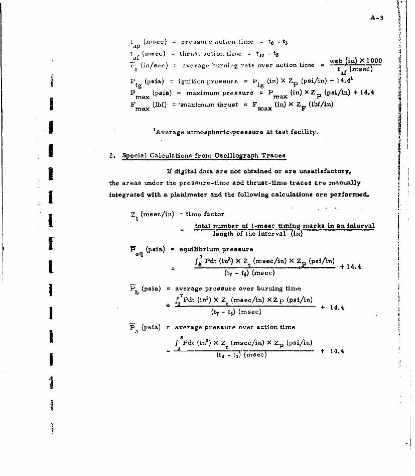
A-3
tap (nsec) pressure action time to -t3
taf (msec) =. thrust action time -- t.1 - ts
7, (in/see) average burnting rate over action time w ia taf (msec)
* (psia) ; ignition pressure =P (in) X Z (psi/in) + 14.41
P (psia) - maximum pressure = P (in) XZ (psi/in) + 14.4max rnax P
Fmax (Ibf) "naximum thrust = Fmax (in) X F (Ibf/in)
I 'Average atmospheric~pressure at test facility.
1 2. Special Calculations from Oscillograph Tracesf
I If digital data are not obtained or are unsatisfactory,
the areas under the pressure-time and thrust-time traces are manually
integrated with a plahimeter and the following calculations are performed._-.II
Zt (msec/in) time factor
total number of 1-msec timing marks in an intervallenigth of i;Lxe Intorval (in)
" (psia) equilibrium pressureeq 7
4 Pdt (in2 .) X Z$ (meec/in) X ZP (psi/in)#I R 14.4I t7 - t6) (macc)
i P1 (psia) average pressure over burning time
S Pdt (in2 ) X Zt (msec/in) Xzp (psi/in)
I (t7 - tZ.) (msec) + 14.4
S(paia) = average pressure over action time
"f Pdt (in2 ) X Z (msec/in) X Zp (psi/in)
I(t 8 t 3) (meec) + 14.4
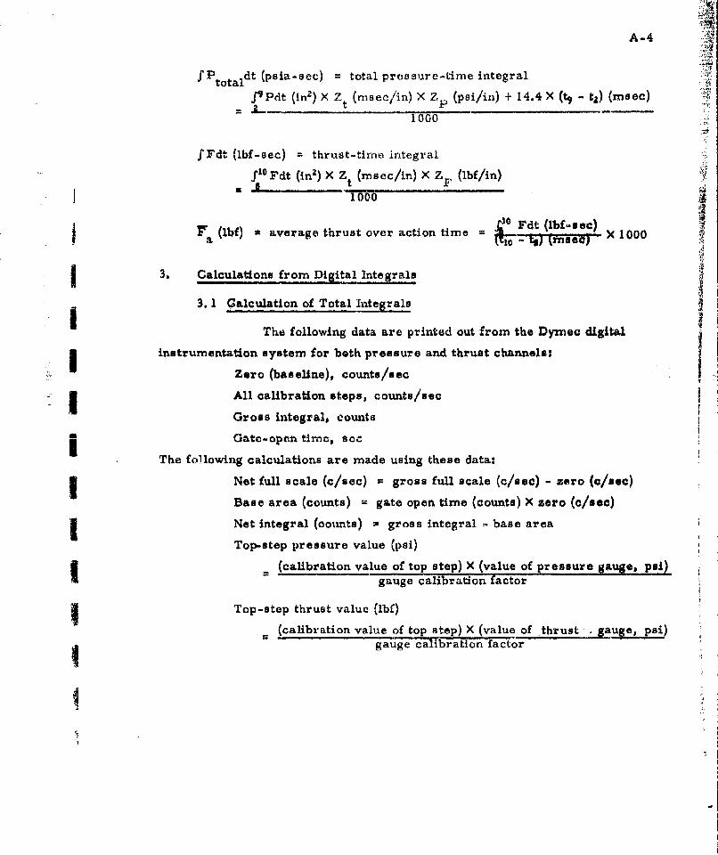
A-4
f P dt (psia-sec) =total pressure-tinie integral:-Atotal
f9Pdt (in') X Z~ (nscln X Z~ (psi/in) + 14.4 X (tq ta) (rnsec)
1000
f Fdtq (lbf-sec) thrust-timne integral
1000
ra(1W) average thrust over action time r dt (b-se)kr1 tnec) X 1000
3. 1 Calculation of Total Integrals
The following data are printed out from the Dyniec digital6
instrumentation system for both pressure and thrust channels:
Zero (baseline), counts/sac
All calibration steps, counts/secGross integral$ counts
Gateopopn timeo, secThe following calculations are made using these data:
Net full scale (c/eec) =gross full scale (c/eec) - zero (c/eec)
Base area (counts) =gate open time (counts) X zero (c/usc)
Net integral (couxnts) =gross integral -base area
Top-.step pressure value (psi)
(calibration value of top step) X (value of pressure gauge, psi)I gauge calibration factor
Top-step thrust value (lbf)
(calibration value of top step) X (value of thrust Sauge, psi)
gauge calibration factor
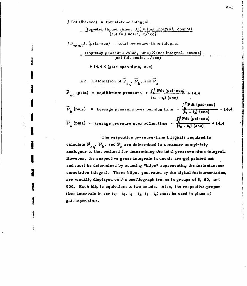
A-5
f Fdt (lbf-sec) thrust-time integral
(top-step thrust value, ibf) X (net integral, countsL(net full scale, c/sec)
JfPtotaidt (psia-sec) = total pressure-time integral
= (top-step pressure value, peia) X (net integral, counts)(net full scale, c/see)
+ 14.4 X (gate open time, sec)I__3.2 Calculation of Peq' Pb' and Pa
R P- (psia) = equilibrium pressure =fI Pdt (psi-Aeq) + 14.4
Ieq (t7 - t6) (sec)I~ 7?Pdt (psi -sac)
Pb (psia) average pressure over burning time = t t _) (14A
" I f•Pdt (psi -see)
(psia) average pressure over action time +1 4.t (se') jThe respective pressure-time Integrals required to
I calculate Peq' "P,' and P a are determined in a manner completely
analogous to that outlined for determining the total pressure-time integral.
I However, the respective gross integrals in counts are not -printed out
and must be determined by counting "blips" representing the instantaneous
I cumulative Integral. These blips, generated by the digital instrumentatioN,
are visually displayed on the oscillograph traces in groups of 5, 50, and
500. Each blip is equivalent to two counts. Also, the respective proper
timc intervals in sec (t 7 - t 6, t7 - t3 , t8 - ts) must be used in place of
Sgate-open time.
Itze
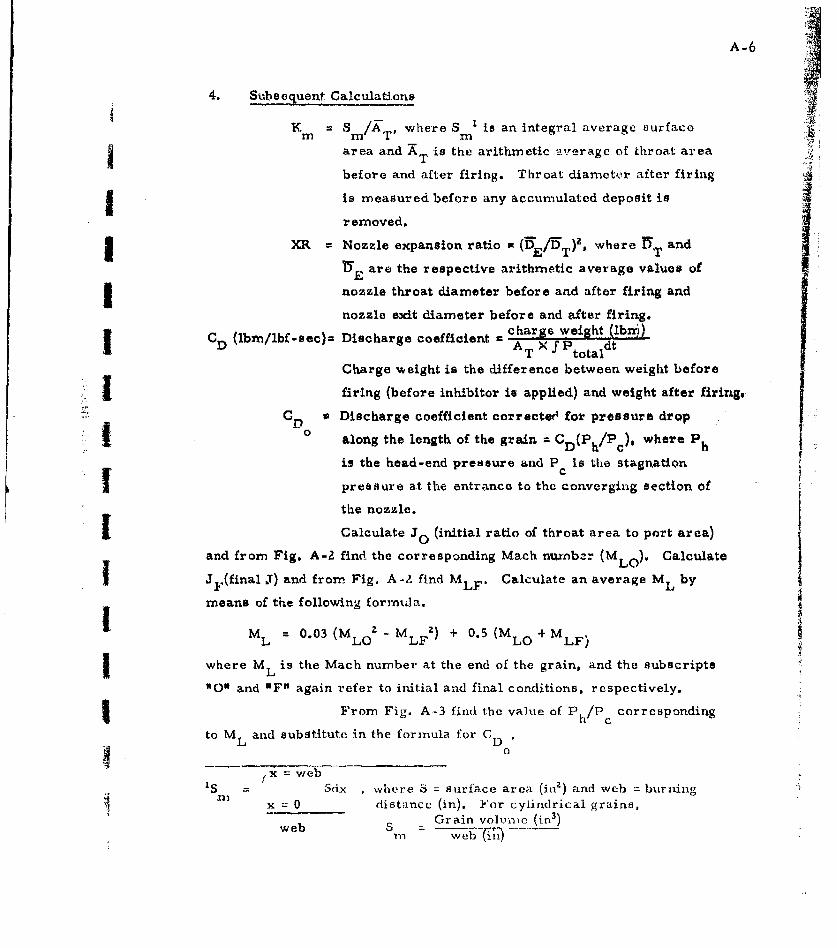
A-6 j4. Subsequent Calculations
K S /A where Sml is an integral average surfacem m VT'area and AT is the arithmetic average of throat area
before and after firing. Throat diameter after firing
is measured before any accumulated deposit isremoved.
XR Nozzle expansion ratio = (DE/ 5 T)Z, where UT andr
E are the respective arithmetic average values of
nozzle throat diameter before and after firing and
nozzle exit diameter before and after firing.
CD (Ibm/lbf-sec)f Discharge coefficient charTe weight (fbP)Df A T ) f Ptotaldt ..
Charge weight is the difference between weight before
firing (before inhibitor is applied) and weight after firing.
C D a Discharge coefficient correctees for pressure drop0. o along the length of the grain = CD(PhPc where P
is the head-end pressure and P is the stagnation
pressure at the entrance to the converging section of
the nozzle.
Calculate Jo (initial ratio of throat area to port area)
and from Fig. A-2 find the corresponding Mach nu'nbzr (MLO).' Calculate
I JF(final J) and from. Fig. A-Z find MLF. Calculate an average ML by
means of the following forrinda.1.ML = 0.03 (MLO - M LFZ) + 0.5 (MLO + MLF)
where ML is the Mach number at the end of the grain, and the subscripts
"O0U and OF" again refer to initial and final conditions, respectively.
From Fig. A-3 find the value of Ph/P corresponding
to ML and substitute in the formula for CD
I x = web
'S = Scix , where S = surface area (inZ) and web = burningx 0 distance (in). For cylindrical grains,
web Grain volcnmc (in 3 )r web(IT

A-7
.60-
.50
ML .40
.20
.30 II
., .2 .3 .4 .5 . .7 A8 .9
1 9 FA-2 Mach number as a function of J for 7=I,2.
"70
-i -oML AO
1 .30-
.20-
1I I I t K 1 I I I I 1 I I j J I L
S1.00 1.05 1.10 1.15 1.20
Fig. A-3 ML OS 0 function ol h/L Ph/PC

A-8
32.16 (ft lkxiJb
c* (ft/sec) characteristic exhaust velocity D (lbr/bfsee)C Fat /lbf -sec)__:
Isp4lbf-sec/lbm) = delivered spccific impulse Ldtk ( ibm) - er charge wt. (Ibm1
?'n (lbin/sec) mass discharge rate c tar (m) 10t f Imec
C F = moasured thrust coefficient r: Iscpibf-sec/1bm) X CDý (lbm/lbf-sec)
CF. corrected thrust coefficient = Fo0o (lbf-sec/lbm) X CD (Thm/lbf-sec)
F?000 =specific impulse corrected to 1000 psia chamber pressure, optimum
expansion ratio at sea level atmospheric pressure (14.7 psia), and
0' nozzle exit divergence angle.FI'rc ctd)7III
CF (std) is a function only of specific heat ratio 4y) and is
taken from a table of such values.I
LF (test) is calculated from the relationship
CF (test) 1= %F (vac) + (1 - ) XR X
where CF (vac) and P/• are functions only of -y and XR
(nozzle expansion ratio) and are ob ined from tables of such values;
P is the average atmospheric pressure at which the firing is madeatm
(14.4 psia at Huntsville, Alabama); If is the actual motor average pressureaover the action time, and X, i the nozzle divergence angle correction
factor defined by
1 12 + COS p
whý!re • is the divergence half-angle at the nozzle exit.
.!

A-9
Isp= F• 0o° when the following additional conditions have been met:Bps
(a) the trace is neutral within Lhe U.mits
0.90 -= -< 1.10
over the equilibrium portion of the trace,
(b) 800 A P 1 lz00
(c) the tail-off portion of the trace is limited by the following:
I tb A 0.87 tap
I fPbdt 0.95
3 •total
Ito0 U Ip Fl 0 0 when the following additional conditions have been met:IB(a) 90goo 1 l00
a
I(b) 8 9 iI
(c) the record is obtained from a 6CS-i 1.4 static-test motor.
4. Exceptions for Micro-Motors
I Some definitions must be revised to provide additional
flexibility for application to micro-motors. The trace time.-points
I atre still applicable, but, the location of these points will depend on tho
shape of the trace to be reduced. Several possible forms of pressurc-
I time traces which may be obtained from micro-motors are shown in
Fig. A-4.
The exceptions for micro-motors are outlined below;
other data-reduction procedures remain unchanged.
'JANAF Solid Propellant Rocket Static Test Panel, Illecommended_Procedures !or the Measurement of Specific Impulse of Solid Prcpellants, DSPIA Publication No. SPSTP/1OB, March 1962.
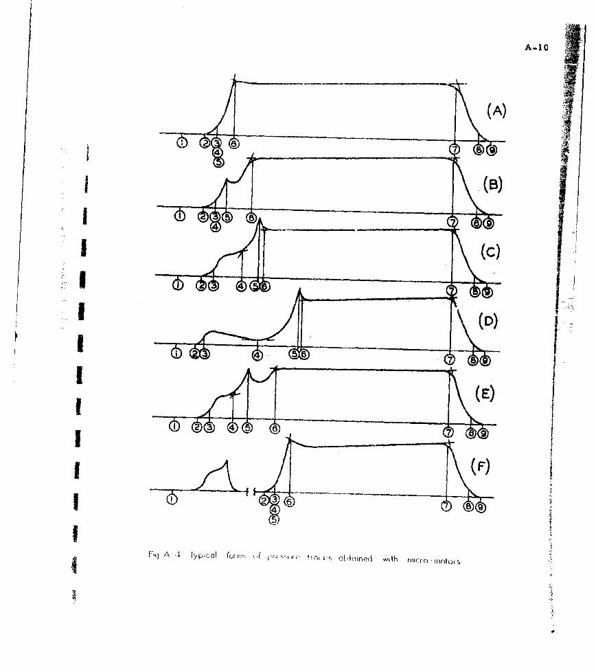
A-10
(A)
_____(D)
IO
I __ ____ ____ ____ __3
I-'q A A T p , l! ý ,i e ih m c
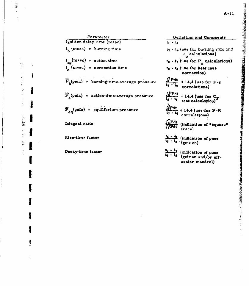
A-II
Parameter Definition and CommentsIgnition delay time (msec) tz - ti
tb (meec) burning time - L4 (use 0LJI '-Ura.•ng r2.C andP calculations)
tap(rnsee) = action time tt - ts (use for P calculations)ap (vea cini at (mnsec) - correction time to - t 4 (use for heat loss
correction)qtt 1.4(uefee Pot)
Pb(psla)" burning-timc-aver age pressure + 14.4 (use fio P-r
I [ •(pula) = action-time-average pressure Pd 14.4 (Use for C-ato ts test calculation)
(poia) equilibrium pressure + 14.4(usefor P-Keq - - t# cnrr elat~ion.)
[g 1 fJPdt traco)
t 2(indication of poorRise-time factor
- (inition)
.i- Decay-time factor t (indication of poori t9.' t6 ignition and/or off-
center mandrel)III
B-I
Appendix B
Calculation of Velocity Lag in Two-Phase Flow
A digital-omnputer program written ia FORTRAN for
calculating particle.veloclty lags in two-phase flow through nozzles of
specified geometry was developed using a simple mathematical model
to approximate the flow process. The mathematical model is described
and procedures for using the computer program are outlined. A
listing of the program and an example problem are given in Appendix C.
I iSource decka for the program are available on request.
1. Mathematical Model
The mathernat3Ical model describing two-phase flow through
nozzles was obtained from a simplification of a previous study at this
SI Division'. In this simple model, the combustion and expansion processes
were assumed to be adiabatic. Dynamic non-equilibrium effects were
determined by treating the particle-velocity lag as a perturbation of a
system in which the particles were assumed to be gas-like. The one-
U dimarisional, isentropic expansion of the gas-like system was first
determined through the use of an effective specific-heat ratio and.an
effective gas molecular weight based on a chemical composition frozen
at the combustior-chamber conditions. The velocity of the condensed-
I phase particles, which were assumed to be spherical, was then approximated
by calculating the velocity of a single particle introduced into the gas-
like system. The coupled effect of the particle lag on the flow of the
gas.-like system was ignored.
The specific-hcat ratio of the gas-like systcm is given?
'1Rohm & Haas Company, Quarterly Progress Report on Engineering Research,
No. P-60-17, Docember 1960.LTUrited I ecOhnolOy CGnter. "High Performa!Lc~e Nozzles for Solid PropellantRtoikot Mnf.ors, I TR -202ý, November 1963.
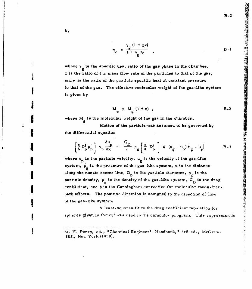
B-2 Iby
9'I (+ Zr)
~ B-1le 1 + zr
whore -y is the specific heat ratio of the gas phase in the chamber,
z is the ratio of the mass flow rate of the particles to that of the gas,
and y is the ratio of the particle specific heat at constant pressure
to that of the gas. The effective molecular weight of the ga-s-like systemis given by
I M = M (l +z) B-2e g
I where M is the molecular weight of the gas in the chamber.
Motion of the particle -was assumed to be governed by
the differential equation
du CDIDS P B-3p updx 2 - pg- p-7
where U is the particle velocity, u i.s the velocity of the gas-likeI ~pgsyetem, p is the pressure of th.ý gas-like system, x Is the distance
along the nozzle center line, D is the particle diameter, pp in the
g Dparticle density, pg9 is the density of the gas-like system, C D is the drag
g coefficient, and * is the Cunningham correction for molecular mean-free-
path effects. The positive direction is assigned to the dir~ection of flow
of the gas-like system.
A least-squares fit to the drag coefficient tabulation for
I spheres given in Perry' was used in the computer program. This expression is
1j. 11. Perry, ed., "Chemical Engineer's Handbook, 3rd ed., McGraw-.Hill, New York (1950).
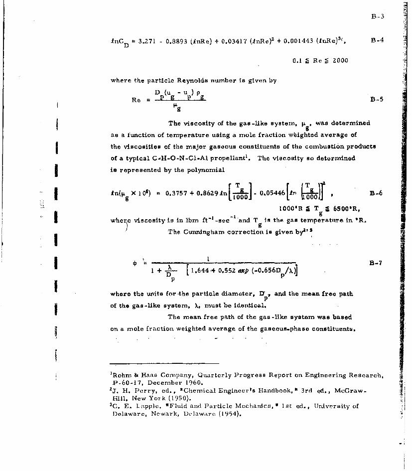
B-3
11nC 3.271 - 0.8893 (InRe) + 0.03417 (.nRe)2 + 0.001443 (In-Re) 3 1, B-4
D
0.1 • Re = 2000
where the particle Reynolds number is given by
Dp(u - up) pRe = g p B-5
The viscosity of the gas-like system, 1i g was determined
as a function of temperature using a mole fraction wbighted average of
the viscosities of the major gaseous constituents of the corbustion products
of a typical C-H-O-N-C1-A1 propellant'. The viscosity so determined
is represented by the polynomial
FT 1I[ T IfIn(p. X 10') -0.3757 + 0.8629T In -i-A- - 0.05446 rA LL I * B-6
9 110001 LU V U_0J
10004R me T S 65004R,whcr, e viscosity is in 1bm-ft'-see" and T is the. gas temperature in *R.
S~ga The Cunningham correction is given by4'
1 + J- 1.644+ 0.552 exp (-0.656D.p/X) B-7
where the units for .the particle diameter, D ., and the mean free path
of the gas-like system, X, must be identical.
The mean free path of the gas -like system was based
on a mole fraction weighted average of the gaseous-phase constltuenti.
'Rohm & Haas Company, Quarterly Progress Report on Engineering Research,P-60-17, December 1960.
2J. H. Perry, ed., *Ghemical Engineerts Handbook, " 3rd ed., McGraw-Hill, New York (1950). r1
3(,. E. Lapple, "Fluid and Particle Mechanics, W I st ed., Urdversity ofDelaware, Newark, Delaware (1954).
-i

B-4
The mcan free path so determined is given by" Z
T= 1.025 X 10⁻⁶ _-8
g
whore mean free path is in ft, temperature T is in 'R, and pressureg
P is in lbf-ft-2.g
The nozzle geometry employed in this analysis is shown
in Fig. B-i. The nozzle is composed of a conical converging section
having an inlet diameter D and a. half-angle a, a rounded throat section0
having a radius of curvature R and a throat diameter Dt, and a conical
diverging section having a half-angle p and an exit dlameier D . The
coordinates of several reference points in the nozzle are shown in
parentheses. Similar nomenclature is used to describe the nozzle
SI in the computer program.
| (0,0)
I
i(o,o)-(,B
IFig. B-1 Klozzle geometry.
'Sir James Jeans, 'An Introduction to the Kinetic Theory of Gases,"University Press, Carbr)dgc (1948).
SzJ. 0. H-irschifelder, C. F. Curtiss, and R. B. Bird, "Molecular Theory
of Ga•ses and iqtiqds, Wiley, New York (1954).
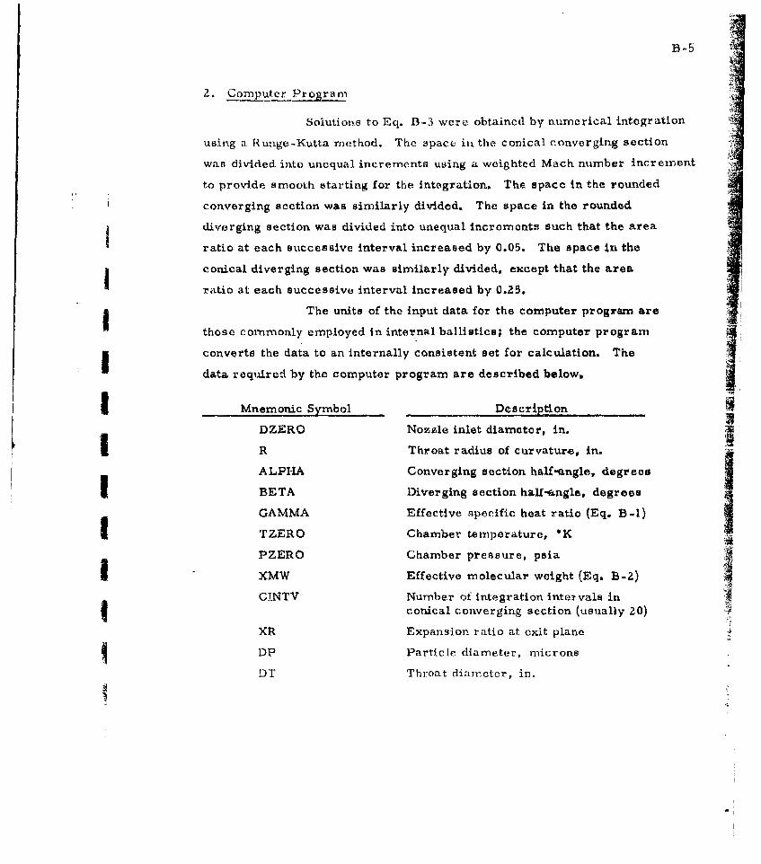
fB-5
2. Computer Program
Solutions to Eq. B-3 were obtained by numerical integration
using a. Runge-Kutta imethod. The space iii the conical converging section
was divided into unequal increments using a weighted Mach number Increment
to provide smooth starting for the Integration. The space in the rounded
converging section was similarly divided. The space in the rounded
diverging section was divided into unequal increments such that the area
ratio at each successive interval increased by 0.05. The space In the
conical diverging section was similarly divided, except that the area
ratio at each successive interval increased by 0.25.
The units of the input data for the computer program are
those commonly employed in internal ballistics; the computer program
converts the data to an internally consistent set for calculation. The
data required by the computer program are described below.
Mnemonic Symbol Description
DZERO Nozzle inlet diameter, in.
R Throat radius of curvature, in.
ALPHA Converging section hall-angle, degrees
* BETA Diverging section hal-aengle, degrees
GAMMA Effective apecific heat ratio (Eq. B-1)
TZERO Chamber temperature, *K
PZERO Chamber pressure, psiaSXMW Effective molecular weight (Eq. B-Z)
CINTV Number of integration intervals inconical converging section (usually ZO)
XR Expansion ratio at exit plane
DP Particle diameter, microns
DT Throat diameter, in.
The output format consists of a heading, a listing of Ithe data, and a tabulation giving the particle velocity in ft-sec the
local expansion ratio, and the relative velocity lag (u - u )/u as ag p g
function of the distance in inches from the nozzle inlet.
I 4I
I II
II
!II

Appendix C
FORTRAN Program for the Calculation of Velocity Lag
_0_ ::::: VELOCITY LA G N TWAO PHASEL 6 W
00000 CQAJ 00 E _______T____E.SOE~
0000 CCOOMPAI E ANYEAAAOTD TA T7
Q0 0 09 0TB... LO, HZ ,C.)AC1 ) l __
00001 2 XMACH, HMACH, YMACA. X1, X2, Yj, Y2. 6UR. YXR,OUP
00001 I ! EAD2.OZEBO.R,ALPMfA.OOTA,GAMMA,TZERO,PZEVO.0000 2XMA,CINTV,XB .DP, 000034 2 FORMAT .5F 4.8)
00043 sfi DUERO_q00047 0__2 = A ___
00053s 0i ZALPHA00057 04 2BETA___________I. 00063 S5 GAMMA
00073 S7 =PZEROý00077 SO8 BMw
00103 4 02R/20 OEO1
00117 ALPHA *ALPHA/57 ..../100125 BETA BA8 TA/57.295..
0 0 133- -1 Z EARO - Z E 4 CF-I. t)400141 PZF!MG PZERO.144.0
00172 4 rORMAT(IH1200(25H VELOCITY LAG CALCULATION//I 0112 eT-7rZ rwT.o 6""h )9 . "V L ALA 9O00172 2 4154 BETA F9.5 / MH GAzMMFA 9.'5.2OVl H IIT4ZEMOl' F9.2,
00356__.. S9 ..0DDOZ62 510 SinP00366 DT - 0I/12,0 ______________
00404 PBINT7,CINTVX.S06 51 S90D417_7 ruRFroMWA'Ttfx0v4c w TT v - 1 6 y500-4mp o. 5 ;1-6 Rt p r95.P0404 27X5H0T - r9.51/00a4 70 C . PETITGORNPRECOMPUT&TIONS ---00470 RHOP *3.97-62.4
00502 RHOZE (PZERO-XMA)/(TZERO.1546.0)10520 -0TAI :2.0/(GAkMA. i 1.)00534 ETA2 ( GAMMA - 1.0 )/iGAMMA - 1.0)00357 ETA3S- fGAMMA-io1.0m/2.0 -(GAMMA - 1.0)) -
00572 0054 ETA3 - 1.0
00610 ETA6 I 0/4GAMMA -1.0)00624 - TA7 .1546.0-32. ;IW/M).2.0.GIMMA.ETA600642_ ETA8 4 * 3./(0.VH ,P)00660 L-CALCUATEO OZiL; p A pA M FT0AS-- - - -00OA6 CALF A COS(ALPHA)~0066 SALFA1 51N(AýLPHA"
-00674 TL~A ALA'C ALFA
II

00710 SHETA =SIN(9ETA)00716 -- - LT& SA/CAT007?' A =(OZEPO - DT *2.0 R (1.0 O_/ _CALFA 1 .0))00724 2 (2 .0 .TALrA )-00764 8 R - DT /2.0 ____ _______
01005 F - R CALFA01018.6 ~ G *- SESETA........- .- - ..01026 H 8 * A *CGETA01037 XA0/.)SIT R
01055 YK q (XL - H)/TBETA
01067 A RýAA [PI/4.0(.DZEOAO.201113 .- A4R.AF PI.F*.201131 AHRRAT (PI/4.0(.DT.*2011-56 ARAHA PF-irl'.201173 AREALtPI.0L*.2
5T2T0~TAAREA07IARE001217 X4F ARFAF/AREAT01225. .ORH AREAH/AREAT - -- - -01233 XRL y01237 60 TO 45...............~.. .01241 C SET UP PRINT FORA ERROR WHEN MACH SUBROUTINF ITERATIO401241 ff O~UN'r~R01241 8. PRINTAI9OVR7O~mD~r02L.
01244 9 FOOMAT(28H 1TERATION COUNTgERCEA012675 . OTOs 0.001301 CALLGI CALCULATIONS, IN050) jG5CTO-- RZL
01316 46 PRHINT4701321 47- rOýMAT I I17HCONVERGENCF ERROR --.01340 Go TO 4 4I 0T32~B FfTTEST18.8.17-01350 10 OMACH = ROOT01354. .- CALL MACH(GUESS. YRF...............-01361 IF (HOOT-i .0(49,4A,4601371 49 IF(ITEST(08,81101317 11 FMACH =ROUT
Ct4DC- CrLJLlTF-Q4 IEl"TFD I CEEN-1= -VFRArRO'-SECT rON01403 OELX=CINTV.(CINTV.,1 /2.01:415. .OOLM1-(rMACH-OMACH)/nELo.......01425 DELM2%(1.-F'MACH)/0ELX0143-5 C PREFIX Y*DENOTES PRESENTr PARTICLE LOCATION, PRFFIAZY'01435 C DENOTES INCREHiENTED LOCATION, PREFIX H DENOTES MID-U43'5-C'-- P~f -U--Y IRTERVA-t -31JFFTX 1AN-2-CORRESPOPIýThTO01435 C X ANI) Y POSITIONS, RESPECTIVELY.01435 C'- SEI DATA FOR'INITIAL LOCATION - . .01435 01 0.0
01447 000 XAO
001457 MM 1
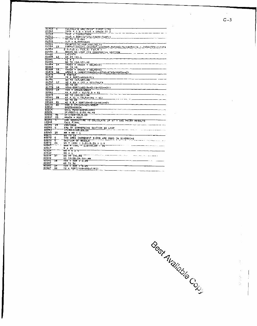
C-3
014630 G (ALCULATE AND-TRMN FIRST LINE01463 TERM 1 .0 - ETA5 - OMACH -- 2
01511 UGAS_*SORTLETA7.(TZERO.-TeMP)) ____ ___
01533 Xd- 0.999.UGAS01541 PRINT02.Xl.XUP.XXR.DELTA01554 12 FORMAT(20X142,10X224UP.12HX0R,9X5HOELTA/1825HCINL),7X5H(FPSI,17XF6
054 2.3. F12.1, F12.3, F12.501630 C REGIN DO LOOP FOR CONVFR-G-,TGSECTION__________
01635 1.3 DO 24 l1-1L01641 XI I01646 GO TO (14..51.KMM _ __
01664 GO 7 O 16 ________________________~~r6~~r4C DM~*~iWTELM2. XI016736 16 09062 = (AREAT/YMACI4O.IETAI.ETA2.YMACH..2)016f *TAJ01735 Y2 - SQRT(AREA2/PI)
01757 17 02 - Xi - (Ti - Y2)/TALFA ________________
01773 18 X2-A-SDRTcA9SlR..2-(B-Y2)..2))020535 19 YXR - AREA2/AREAT02061 HO (02 -013/2.0 + X1
02073 GO TO (20.21h.MM02101 20 MY y TI. TAL.FA.(HX - 01)
02116 21 MY *9 -SORT(R*.2-CA-4XO..20
02170 w2 HX R *(PI*HY..2)/AReAT02210 GUESS.XMACH
02221 lF(ROOT-1.0ISO.46,46
02237 23 I4MACH ROOTuzw4a L USE UU0ROUUINE TO CALGOLATE UP AT-Y AND) PRINT RESULTSC2243 CALL FINALOZZ46 W4 CONNU02253 c END OF CONVERGING SECTION DO LOOP
02263 25 MM - MR +uirell U ru 1402273 C TWO AREA INCREMENT SIZES ARE USED IN DIVERING
02273 26 ON (XRH - 1.0)/0.25 *1.0
02317 N X N
02332 MM I
02342 GO TO(20,2R,30(,MM ____________________
02357 GO TO 30T7"1-77--Yx XON
02367 30 Y2 50SRT(;XR.;ARFAT/PI)
C /
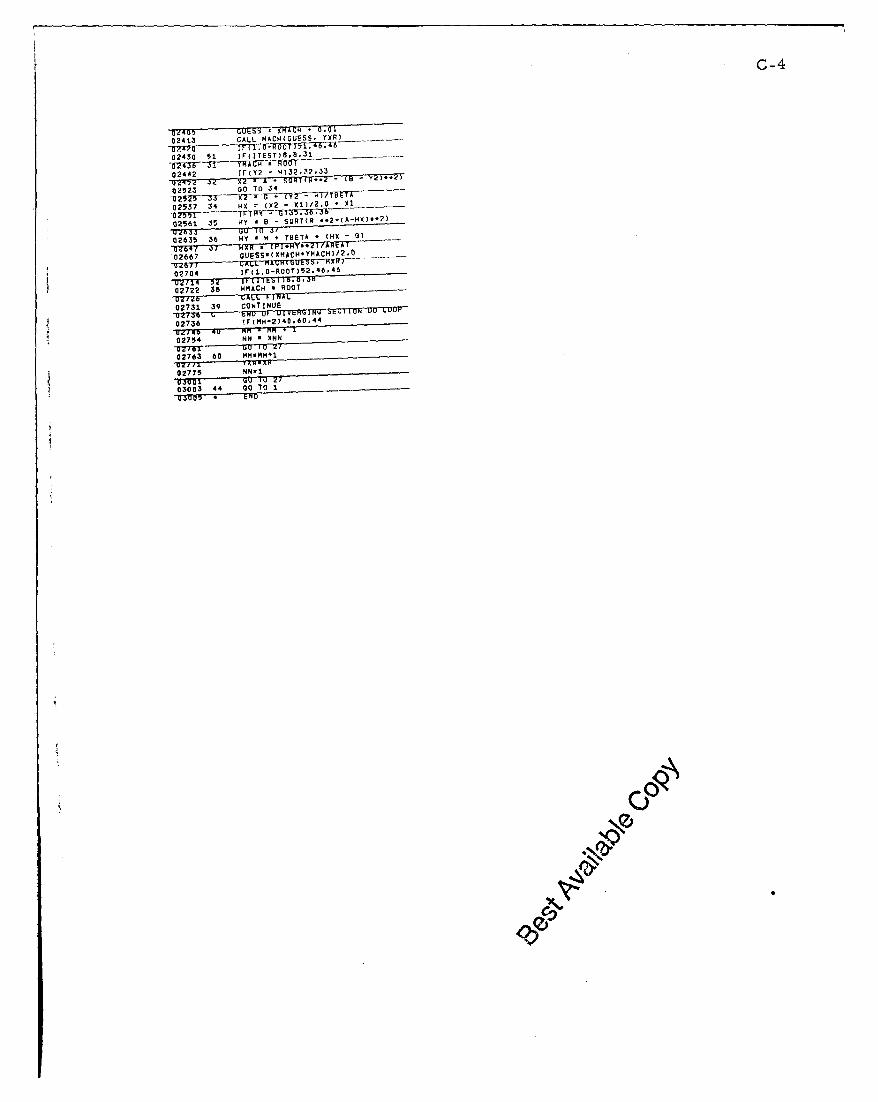
C-4
0241.3 CALL MACW4GUESS, YXR) ____
02430 51 IFIETSB3
02442 11. Y2 H)32,12,33
0 2523 Go TO 34
02537 34 NO (Y2 - X11/2.0 X 1(
02561. 35 N1y B.,,; SURTIR *2-(A-HX)..2)y'7.3' 1,0 - G)02635 36 HY H *TEA*(I-5
02667 ,UESS*IXMACHIYSHACH)/2.0Ol..
02704 IFcl.0-ROOT)52.46,46
02722 38 WMACN - RDOO,
02731 39 CONTINUE
02736 !(M24.0 4
02754 NN - XNN-o'27br ,10/
02763 60 ""::,N1
02775 NN-1
03003 44 030 TO I
* 6 1 1A
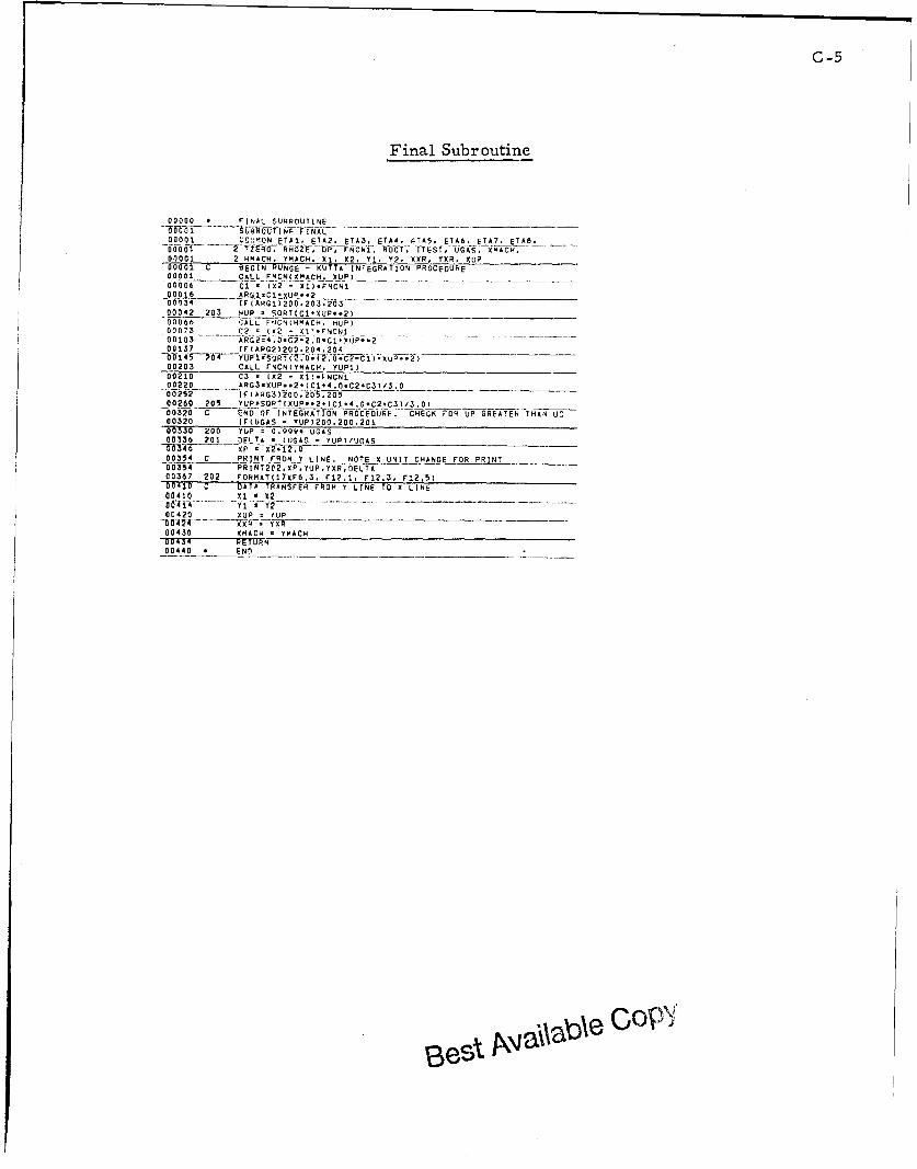
C-5
Final Subroutine
00000 r INAL SUNROUTINE
00001MC::ON ETAl. ETA2. ETA3, ETA4. FF65. ETA6. ETA7. ETAB.
100o r001 ZR7 _ , Dwr1- OT_. _ITEST, UGAS. ýJiý_ _-IACH.-
,0000 2 HMACH, "MCH "', "2" ')(. Y2XFR UE00001 C BEIN RU!Ng -ý UTA INTEGRATION PROCEDURE
0090 CAL FNCN(XMACH. XUP)__ _________
00006 Cl - (x2 - Xi).VNCNI
00134 IF(ARGI)200,203.z0300042 W03 4UP - SORT(Cl-XUP..2)00066 CALL -'JCNRHMACH. HUE)00073 C2 (X2 -_, I' *FNCNJ00103 AR12s4 .0.C2-2.0-ClTUP..2 -
00137 IF(ARG2Iý200.204.204___________bW145 71 0 0-yoi2S0RIC_ 2 )- uP'.2 -_____
00203 CALL FNCN(YMACH, YUPI)
100210 C3 12. - 01.NCNI-00ý220 & RG 3XU P :2 !1(C .4.0.C2.C30,3.0__________00252 I( A RG3J2o.200Z5 , 205002 -60 ?05 YUP-SORT(0UPE..2.ICD4,0.C2,C3)/3,0)00320 C --- ND (IF fINTEGR-ATION PROCE6DUE. ECHKe FOE UEGRATN HA U00320 IF(UGAS - YUEI200.200,201
0 0330 200 TUE 0.99Y- UGAS010336 200 DEL -
TA . ((GAS - YUPI/UGAS
00_O3 54ý C ___!INT FROM T LINE. NOTE X UNIT CHANGE FOLR PRINT00354 PR I NT2E2_FP.yE.UpEY0RE00367 20? rONEATIITXF6.3, F12.1, F12.3, F12,5100410 C DATA TRANSFER FROM Y LINE TO 0 LINE
00 410_ 01 'I X2a 064 i4 )'1 T2ý_00420 DUE TUE_______ __________________
00430 XMACH YMTACH00434 RETURN0040 END __ _______
~eGo

C-6
Function Subroutine
00000 F UNCTION SUBROUTINE__________________00001 UB IEFNCN(XMOCK. UP)00001 COMMON ETAI, ETA2, ETA3. ETA4, ETAS. ETA6, ETA7,
00001 2 XMACH, HMACH, YMACH, X1, X2, Yi. Y2, XXR, YXR. XUP00001 C EVALUATE RUNGE - KUTTA FUNCTION IN EQ 300001 -TERM - 1. 0 - ETA5 - XMOCK -.2 _________
00038 RHO - RHOZE/TERM..ETA600053 UGAS - SORT(ETA7.(TZERO - TEMPI)00071 TRP1jOG(TEMP/I000.I
0010 XM (.375 - .0082Y * IERM1 - 004600105 2 TERM1..2)/100 000.0 ____________
00146 XLAMB 2.052(H..0600162 RATIO . LAMB/DP
OO 7P li T~T~~i l~TA 4 I .5 EXPC-0.656Q0170 2 /RATIO)))
00223 RE - ABS(DP.CUGAS - UP).RHO/XMU)- ~~~~00250 RELOG-ELOG(RE)______________________
0025 IJA0_-_fXPT3.P_- 0.8893 - REMO O.0341T _00256 2 RELOG *.2 * 0.001443 * RELOG *.3)I 0b N~f~O~R O~R iTOGAS - UP) ? IHI00334 2 ARS(UGAS - UP)00402 RETUWWN0040.6 E NDl____ __________
CI 7
C-7
Mach Subroutine
00000 M ACH SUJBROUTINE0-006 .i -SUsiRfUT INE -MA CH(ROOTI. P AT 100 0001 OMMON E TAI., ETA2. ETA3, ETA4, ETA5, ETA6. ETA7.00001 2 FlA8, TZERO. RHOZE.- DP, rNC'4,1 HOOT, ]TEST, UGAS.00001 2 XWACH . RHACH. YMACR, 01. X2, Yi. Y2. XXR, YUR, XUP-oo-o--r- - CALCTJL0T'rFMkONUw O00001 K-I00005 100, TpwM - (UTAI . ETA2 - ROOTI *.2)00034 TERM1 TERM.-9TA300043 ROOT -ROOTI - (RATIO - T6HM1/ROOTI)/(TERml00043 2 ROOTI 0-2 -TERM..ETA4)0MT-Sf 7 T -gT rr UITtONVFPO;ctt Q~G RFl XCCI1)RACY -
001.13 10IAHSIROOT - k0011) -0.0000)001.101.102
00156 101 RETURON00162 102 ROOTi ROOT00111 K -- K *I00177 C' RETURN TO PROGRAM IF ITEkATIONS ROCLED 100
b0T ~ ~ n -rfr~ i sJ., Iff ~n In00207 33 ITEST *-10021' Go0 To t0000211 * ENO
\fa 0
C-8
Example Problem
VfL0C0TY 140 CALCUILATI(IN
I "I~~~~iEF7 T9 R0T •1T.-Iw.yU' OtP'R 89 •-- ;o -0 (] 0iI• .... RT:T-'= "-f5".O"O'd
GAMMA : 1.17300 TzRO = 3705.62 PZERO * 1000.00 M4 S0.94359
Trv-r- ---20 -- ----x '-- .43f--- nr .. -]O ..... ) T- ro- .f. 50000
X OP XR DELTA
0.000 354.1 5.971 0.00100. -.. 5"7[-6... 796. 0-02096
6_.025 373,3 5.475 0-035400.04M+ 4G2.5 5.056 0.0450.075 441..5 4,589 0,04611
0.132 546.9 3.669 0.06016
j.11!5 686.3 2.894 0.07749U.2U9 761.7 .0.0/9 u. O/d9J.231 855.6 2.301 0.n9010
0,269 1049.7 1.865 0.12191
0.299 1262.4 1.551 0.148800.312 1373•.4 1.42Y 0.163490.322 1485.9 1.321 U.17912U.332 --- F 9 . 1.242 0.195850.340 1709.4 1.172 0.21391.-1,3-6- 1--16 2• 1• 116 0. 23364
3.352 1916.0 1.971 0.25547r) .352 1917.4 1.070 0.255910.352 1921.6 1.U69 0.25679
3.53 )1935.1 1.064 0.25970
.1.354 1957.1 1.056 0.26,378. 654 1971.6 1.0'5 0. 26609
,. 355 1986.7 1.047 0.26949
q-.-3 5 -6 ZO3U .4 1.042 0.270910.357 L131.0 1.037 0.27329
0.459 2084.d 1.02, 0.27771.1 Sh 2116.. 1,021 0.27.76d
0.362 - 159.9 1.1 ... 0. 76148-d-3b4 2189. - --- i .... 23i•8n.366 "28.8 1.l007 0.28454
-.0 .28-5843.369 291.3 1.00? 0.2870A.6'71 2. T T. Ooo u .29 7 .1
A ., 7,i 2414.0 1.•0OI 0.29(1-47- - -- -r~A-5 5-bo6067*
U.422 3448. i1a,0 • (1:2'214o.4 9T -- -37 "3 : T l 7150 -- - 0-.i-S-' 6 -. .. ... ... .
U .•66 3980.4 1.?00 0.1767L)a .481 -177.Q 1 . J. 5 I , 162610.6b7 4166.4 1.,00 u •12237
0308 5293.1 1. 1 0. 1065 45(.763 5606.2 7. (003 0.09513___________ -- -5~ --••~ .. 2 i •u 0--------_----"-,-
(I .919ý 6n64.., 5n,)1 9.01C.6501.991 9'24.4 .5 007e47I .U6 6-.5/ 9 u a l 0 0 1 t0tM
1.109 ,612.3 ,.5if 0.,6901I. 751 6713.9 • • .910/. I (
1,,111t 6K06.4
4 aId 0 0.11.'-- -7 -. t7 - .-t - 4 . , 0 : 0 6 4 5 b - - - - - .
1•427 6'104. 4.,n;) 0063.30.477 7311,4 .1 4 . 75,1 0 .062;.0,
.( )l• } • . / 6. 26- 0.1i(0[(1(.02 •276. '0.1) .05914
7. '. (10 0 .0 71 H6
1 17?, 1(0'7 ., 761u 90-,7050 .0.0• 041
14 1 10 . 0564301. .' 4 7. 0 n. Q), S'.O• 4 1
2 , .. 1 ,5,1 n 4. 1
t , +',', / .+:,-T. ý,, o oI , . I)+ = +
.0 , ' .+''4 97
1. o .(,(1i,97. '4 1 1A I . . O, 1 f. 't', 72
qes ~ s~ CoP'I
D-1
Appendix D
Velocity Lag Curves for RH-P-i IZ Propellant
Curves of A versus nozzle throat diameter for particle
I diameter (N) values of 0.5, 1.0, 1.5, and Z.0p and norzile expansion
ratio (XR) values of 6, 8, 10, and l Pro shown in Figs. D-1 through
D-6 for the Rohrn & Haas .75C.50, ZC1.5, and 6CS motor nasale.;
for the USAF BATES motor nozzles; and for the Aevojet 10CS-Z500
II motor nozzles. These curves were generated using the FORTRAK pxogranr
described in Appendices B and C. The thermodynamic input parameters
I used were those determined for RH-P-1 12 propellant (GAMMA a 1.141,
TZERO x 3389'K, XMW a 27.452). The parameter PZERO a 1000 psia
I was used in all cases. The nozzle configuration parameters used are
listed in Table D-I.
Table D-INozzle Configuration Parameters
rMotor .75C.50 ZC1.5 6C5 BATES IOKS-2 00_
DZERO 0.75 2.00 6.00 11.73 7.125
R 0.4375 1.167 3.50 3.00 4.0
ALPHA 45 45 45 45 30
i BETA 15 15 15 15 15
4'Estimated from non-dimensioned drawings.
I
III
t~~ri i -o 4 4't ff4
I 1T I
I t 4 '.. .. I 1
1i it:: 1i ' I, -I -t.: f 1 4 i
1 1f' f~j- I
J- -r <>t 1*HtflL.K-..11 , 1J2 ti' I- 1 :JL Ll 4 ii ,--
liii'MI L+1- f~1-:
i t I' ! ' 1-1iI I
.30 I-Jill
020 04 0 0 12 14-1FRCIOA VEOCT LAG -
Fry -I Vlociy lg cuves or 70 ~ motr nozle
D-2
4 i A
I t
Wit Týý-I J. I- - i
t I I l I 1
Iii at Ili iIt t~lt
- 4.- !~l Nt'1 I j
IT1 T". fI ITIfI. Ij
tI I
.12 .14 .6 A .20 .22 .244IAL VELOC ITY LAG A
44'-
+ *;*- -- I* i H
-IIt
1I t
ITT-[
j~f 1 ~ ijI It.I j iiii.'- 4
.35 20 221446 .2 3 3
FRATINA VLOIT L
R.30D2Vlct a uvd o 5 0mtrnzls
I aI
1-1
I Hj
ita I~t I
HF' 4-.i IT
I r '['*1 41-1.1 -1lid-
-~ d I III 111 I-it 1 -1 ti~ I-I i Il' IiTi
I IT
ii,
.28 .30 .32 .34 .36 40 AACTIONAL VELOCITY LAG A
k
.90 ..-
'.80 .- - - -
---------
- - - - - - - - - - - - - - - - - ----- ---
FRCSNLVLCT LA 1-TFi.503 Vlct njcre fr215 ioo oze
D-4
I~~t I I I.-F
11. 2-4
.2 .4.16 .18 .20 2-2 .24NAL ELOITYLAG -A
-. -.1- J ..
CT
L1i -. - -
4 .0 --- -- -- --
0 -J-
3.5
8 3.0 - ----
FRACTIONAL VEOCT LA - LTFig~~~~~~4- D- Veoiy-7-uvsfo C oornzls
~0

ITI-- - --- --
H+H
-474]
I 11Z.
J- U
40 -
0z3.5
Z .5
.01 .02 .03 .04 .05 .06 .07 .08 DFRACTIONAL VELOCITY LAG-
Fig. D-5 Velocity log curves for BATES motor nozzles.

D-6
.1- - - - -. .. - - -~ .**---.---- - -- *-- -~
+ Ef -
4:11
-- -- .----
. .- ----t- ---
------ --.-. ----- ------ -- ----- ----------
RACTNA VLCTY LAGit-- - -
nozzles.
U, ki:kj01~
-f 4.5iiTI V~ it Q4 35
f I J I I(
iI~IjJZ 2.5 1;I
I~~~ I It ~ '
.01 .02 .03 .04FRACTIONAL VELOCITY L,
Fig D-6 Velocity log curves for IOKS-2500 motor nozzles.
D- 7
LIo
FT. 4 .I A i4 j I
~~~4 -4-- i --
-7 -Ii- T h ------
I' HIII I':fr~ij+
J T 'l
jiI '- -' ~ '
II-IT.TL1 III 1 1If- 11 J~f:-fjNIT faij~i
J-
.- -' ?I
j I A- . - If ~ , I4I- I l
.03 .04i .05 I Ft06ONAL11 VELCIT LAG- A

IE-1
Appendix E
Example of Scaling Factor Determination and Specific Impulse Prediction
1. Scaling Factor Determination
Assume that the data shown in Table E-1 has been
obtained for a certain propellant through static tests of micro-motors
Sat? lO00psia.Table E-1
MIcro-Motor Static Tent Data
GrainLongth K r--l t Ala
Motor in ,m in i . '. XIn ien in, .br .F
.75C.50-1.5 1.41 173 0.146 0.60 8.! 0.7,34 1.645 0.0? 189 2416.4
.75C.50-3.5 3.41 1 71 0,225 0.60 8.z 0.23? 1..653 0.05Z41 252.1
2-G1.5-4 3,88 170 0,386 0,60 8.0 0..130 10.42 0.3306 '5 ,6 .
aObtained as oitlined in Appendix F.
Assume further that the values listed in Table E-II
have been obtained from thermochemical calculations for the propellant.
Table E-fU
Thermochemical Data
Equilibrium Chamber Chamber ChambercK TV, mols gas/100 F_ rels A%03/1 00e_____ gasiCOg_
3629 2224 1.20 3.65818 0.21239
The following parameters necessary for the calculation
of fractional velocity lag (A) and for scaling-factor determination may

~E-,
II now be determined:
Te 2224
Sl T- = 2- -- • 0.38716 (assuming C C )
X 1.0196 (mole AlaOs/100 g) = 1.0196 (0.21239) - 0.21655Sa g
0.21655 0.Z7640I I- u.21655 7
1.,6X(mole gas/i 00 g) 12 .96X 3688 045
P 0.4359 = J.2672O- 0.344PA1.0j
I 1.2 (1 + 0.2764 x 1.267)GAMMA ==1.141MI+ Y , I + 1.2 X 0.2764 X 1.2672 1
* 00 t 100 27.336SXMW fmole gas/100 g 3.65818
The preceeding information, together with the nozzle.
configuration parameters listed in Table D-I would provide the requiredinput data necessary to calculate A values for this propellant using the
FORTRAN program described in Appendices B and C. However, the
curves of Appendix D will be used to obtain A values for tids example.
From curves D-I through D-3 Table E-III may be
formed.
I| -
E-3
'Table E-1I1
A Value from Curvea of ApLix I1) ~A Values f
Motor ) XR N O,. N 1.0 N r= 1.5 N -Nh.0
I .75C.50-1..5(5 0174 0.158s 0.2 356 0.3025
,75C,50-3.5 0.45 8.Z 0.0490 0.1143 0,1811 0.2398
I ZCI,5-4 0.386 8.0 0,.O98 0,0738 0. 1 z8 0.1703
I We are ,ow in it position to calculAto c values fromEq. 29 in the text, thereby generating the q-veraue-N eurvea necessary
I for uicaling-factor determination.
I~ q a -
I! .,,; 1-TnJJ "
S!Taldng motor I an the .7tC.50-1.5 rmotor and motor ZI) as the .75C.50-3.5 motor,1!I- 0.21655 X 0.0490)
I_ - 0,2655_X 0.022 (Z46.4122 X 778.16 X 0.38716 1 - 0..1655 X 0.0490 0.234 XI O0=722 0.3144 X 32.I 74 -1 -70.2-16-55 ~ 0.02189 0.5 1
63,604.84 (1.01021)(60,712.96)i q -0.13005 [i1.010Zl)(17,58474) -7.47492-]
j q 2 1697.9
II
i E-4
For N 1,0-,
jI - 0.21655 X 0.1143163,604.84 - 1 0.21655 X 0.1582 (660,712.96)
0.13:005 _0.21655 X 0.1514 (17.58474) - (7.47492
1 .130S 1 0.21655 X .18
q 1243.3
r For N = 1.51•,
q 63,604.84 - 1,02501 X 60,71Z,96
q -0.13005 (1.02501 X 17.58474 - 7.47492)
I q 1001.1
I For N =Z.0•L,
F N 63,604,84 - .029.27 X60,712.9 6 .I
=0.1u3u5 (1.0292:7 X 17.58474 - ".47492)
q 806.8h :1
We now take motor 1 as the .75C.50-1.5 motor and
motor 2 aa the 2CI.5-4 motor.
J For N 0.5pL,
( -I - 0.21655 X 0.0298 0
q I 0.21655 X 0.0722) 1 .6
0.100 1-0.Z1655 X 0.0298? (17544 -ý'0470 X 10.4I - 0.a1655 X 0.0722) (17.58474) 0.3306
63,806.76 - 1.01873. X 60,712.96q 0.13005 (1.01873 X 17.58474 - 14.81367) 4852.7 4
t
E-5
FFor N 1 .0[i,
q = L63806.76 - 1.03820 X 60P712.96q 0.13005 (1.0382 X 17.58474 - 14.81367)
q 1729.9
For N =1.5}•,
q 63,806.76 - 1.05214X 60,712.960.13005 (1.05214 X 17.58474 - 14.81367)
q -149.6
For N 2.011,
63,806.76 - 1.06220 X 60,712.960.!3005 (1.06zz0 X 17.58474 - 14.81367)
q u-1358U
The q values calculated above are plotted aghinst
the respective assumed N values in Fig. E-l. Two curves result,
one for the .75C.50-1.5 and the .75C.50-3.5 motors, and one for
the .75G.50-1.5 and ZCI.5-4 motors. The curves intersect at
q -1180 Btu/sec-ftO and N = 1.12L. These values represent the
scaling factors for this particular propellant.
2. Specific-Impulse Prediction
Assume that specific-impulse predictions are desired
for the propellant in the 6G55.11.4, BATES, and IOKS-2500 motors.
Estimates made for the pararnetcrs Dt, XR, t 2 , A, and m for these
motors (Pb 1000 psia, K = 170, Fb 0.60 in/sec, density 0.062
lbnm/it3) are sxininmrized in Table E-IV.
* I

E -6
1 41
\J 5000 1Ji - -
.75C,.50-1.5 anld 2C1.5-4
400
3.000.-
D 200 ~{.75CS~iand .75C.50-3.54+
V 11114{4N 1180 *4 f i ±-
wI
0O2.EFETV PATIL DIAMETER.(N)Al.
wi JE I q- ctr fr cIn uT 1 rd, ~mnb

E-7
Table E-IV
Estimated Ballistic Parameters
Motor Sm, in_ Dr_ in XR web, in t , sec A, inz Volume, in3 nm, ibm
6C5-11.4. 194.78 1.21 8.0 0.50 0.94 8 5 . 19 a 97.19 6.026
BATES 620.48 z.16 8.0 1.875 3.53 345.89a 1163.4 77.13
1OKS-2500 915b Z.62 8.0 1.7b 3.20 102.1b 1570 97.34
Obtained as outlined in Appendix F.
Estimated from non-dimensioned drawings.
The next step is the determination of A values for the
.75C.50-1.5, 6C5-11.4, BATES, and 1OKS-2500 motors at the previously
determined effective particle diameter of N = 1.Z1p. This may be
accomplished by plotting A values obtained from the curves of Appendix D
(for the specific nozzle configurations) versus N, as shown in.Fig. E-2.
From Fig. E-2 the following A values are read at N =,1.121:
For the .75C.50-1.5 motor, A = 0.1785
For the 6C5-11.4 motor, A = 0.030
For the BATES motor, A = 0.017
For the IOKS-2500 inotor, A 0.014.
Taking motor 1 as the .75C.50-1.5 motor and motor 2
as the larger motor, we may now calculate predicted specific impulse of
the propellant in the larger motor from Eq. 28, for N = 1.124 and
q = 1180 Btu/sec-ftz.
3 est Q\oP'y
.28 Alt_
J- L - 4+414 14
.20 +275C.50t
1 4
.12
1 ~~~ .0.IAL
j~~~~~- Ij. tI-F~i
10.5 1.0 1.5 2.0
/ E.FFEC.TIVE PARTICLE DAMETER (N) -A

E-9
0100 1 44g 0 n
For the 6W5-11.4 Motor:
1 (.Z655X .1 A 2464) (0. 1 .31105)(1 1110)(17,53-74) j (0,1 3005)(I1180) 6 .02
I . A
(F'10)? *VI1.06800 (60,712.96 + 153.459 X 17.58474)- 153.459 X 13.28884
- �j(P-oo0,z '-C1,06800 (63,411.500) - 2039.29-
I(FlO&)2 Z56.3 I
For the BATES Motor:
i(FI 1 0.21655 X 0.017 1 3.53 X 345.89)
10"). 0.1655 ? 0.178 (63,411.500) - 153.459 .6 X 72.13
(F%10o)a 1.07406 (63,411.500) - 153.459 (16.92765)
(Foo()lz 2•56.0
jFor the 1 OKS-2500 Motor:
Y.1 0 o.2t655 X 0.014 (63,41 1.500) 153.459 3.20 X 10-.1000z 0- 655 X 0.178597.3

E-10
(F~oIW) " -)Fi.07547 (63,411.500) - 153.459 (3.35648)
(F°0,0 )? z60.z
To summarize, based on previously determined scalingfactors of q = 1180' Btu/sec-ftz and N = .121L, specific-impulse values
of 256.3 would be predicted for the 6C5-11.4 motor, 256.0 for the BATES
motor, and Z60.Z for the IOKS-2500 motor.
4
I |
I III
Ir
F-1
Appendix F
I Heat-Loss-Sur face.Area Determination
As an aid in determining the heat,.los-surface-area
term (A) used in Eqs. 28 and 29, Figs. F-1 through F-4 have been
generated. These curves show nozzle surface area versus nozzle
throat diameter for the .75C.50, ZC1.5, 6C5, and BATES motor nozzles.
Nozzle surface area as used here is defined as the number of Pquare
inches exposed to hot gases in the nozzle convergent section only,
1 beginning at the nozzle entrance and ending at the nozzle throat. Nozzle
surfaco area downstream of the nozzle throat is ignbred. The total
surface area (A) exposed to hot gases is the sum of the area of the firing
head, area of Initial motor.case ends (not covered by propellant), average
motor-case area exposed as the grain ends burn back, and the nozzle
surface area.
As an ex4rnplo of Lhe use of thLt curves, co,,sider a
6C5 motor having a nozzle throat diameter (Dr) of 1.210 inch, a motor.caset
length (L: ) of 11.40 inch, and an initial grain length (L ) of 11.25 inch.M inFrom Fig. F-3. nozzle surface area = 44.66 in?, firing head area =
28.274 inz, area of motor case ends = 18.850 (11.40 - 11.25) =2.828 na,
and average area exposed by burning grain ends 9.425 in?. The total
I exposed area (A) 44.66 + 2.8.274 + 2.828 + 9.425 85.19 in z .
II .4
I"
J1.2
I 1 1 -4
T _ T - ... - - -- - - -
L - ~ L
t±I:I
lif qil -"EII
I. . . . . - , 1, I . I. : 1 . -. ,
.141
F-3
if 4%11
J_. - -.- _- .-J
-H--H4
A-0
0NN
A IIL LI.'7 - -- - ----l C4~U l J Z N
C.. U,.
41-1- Ft I f!
it~ ~~I 1 1 - *~
Hdd N
J M44X -A 1.3 - -- - -
OD J
t~~ld HIM u. .. .....I- 0
t
T1 -1
~uI VV ~V~flS JZZx
00
o -- -- - -00
COC
UJ q
(00
+ C~C
0 04
!UJ. -:T
3:)
0C .1 - , +L±.0C
UI~~~~- -3V c~~il TZO