Embed Size (px)
Citation preview
UNCLASSIFIED
An 299 552 RepAaduced
(up ike
ARMED SERVICES TECHNICAL INFORMATION AGENCY ARLINGTON HALL STATION ARLINGTON 12. VIRGINIA
UNCLASSIFIED
NOTICE: When government or other drawings, speci- fications or other data are used for any purpose other than in connection with a definitely related government procurement operation, the U. S. Government thereby incurs no responsibility, nor any obligation whatsoever; and the fact that the Govern- ment may have forraulated, furnished, or in any way supplied the said drawings, specifications, or other data is not to be regarded by implication or other- wise as in any manner licensing the holder or any other person or corporation, or conveying any rights or permission to manufacture, use or sell any patented invention that may in any way be related thereto.

NlO^ RADC-TDR-63-32
Cl HIGH POWER R-F WINDOW STUDY PROGRAM
QUARTERLY TECHNICAL NOTE NO. 2
OO<3:
^ oCZ5LjuCO
1 October Through 31 December 1962
VARIAN ASSOCIATES
PALO ALTO, CALIFORNIA
CONTRACT NO. AF 30(602)-2844
Prepared For
ROME AIR DEVELOPMENT CENTER
AIR FORCE SYSTEMS COMMAND
RESEARCH AND TECHNOLOGY DIVISION
UNITED STATES AIR FORCE , S T ! A
GRIFFISS AIR FORCE BASE
NEW YORK
3 1963
T.'■U
VARIAN REPORT NO. 304-20 JANUARY 1963
ASTIA AVAILABILITY NOTICE Qualified Requestors May Obtain Copies Of This Report From ASTIA
VARIAN associates «II HANHN WAY ■ PALO ALTO, CALIF.
RADC-TDR-63-32
HIGH POWER R-F WINDOW STUDY PROGRAM
QUARTERLY TECHNICAL NOTE NO. 2
1 October Through 31 December 1962
VARIAN ASSOCIATES
Palo Alto, California
Contract No. AF 30(602)-2844 Prepared by: Floyd Johnson Project No. 5573 Approved by: L. T. Zitelli Task No. 557303
Prepared For
ROME AIR DEVELOPMENT CENTER AIR FORCE SYSTEMS COMMAND
RESEARCH AND TECHNOLOGY DIVISION UNITED STATES AIR FORCE GRIFFISS AIR FORCE BASE
NEW YORK
VARIAN REPORT NO. 304-2Q
January 1963 Copy No. 2 5
ABSTRACT
Three fused quartz thin disc window assemblies were fabricated and tested in the ring resonator. Extreme localized dielectric heating was responsible for failure of two of the windows by melting. Failures occurred at power levels of 70 kilowatts cw or less in a nitrogen atmosphere.
Fabrication of a single disc zero degree cut sapphire window was completed and high power tests performed. This window was operated up to 235 kilowatts of power without failure or damage to the dielectric. Steady state power dissipation of this window has been less than any window tested on this program to date. A wlndowtron has been constructed using this device for tests with other window designs in vacuum. The crystal structure of other sapphire discs was also closely examined for spurious effects on window impedance matching.
Two vacuum-tight double disc aluminum oxide window assemblies were com- pleted, with one of them failing in high power test at 180 kilowatts cw at 7750 Mc. This window had a mode free bandwidth of 33 per cent and was continuously cooled by re- circulated FC75, an inert fluorocarbon liquid. The remaining v/indow failed because of excessive cooling fluid pressures.
Three successfully brazed vacuum-tight beryllium oxide half-wavelength block windows were completed and high power tests showed that power transmission was as good as previously reported for this type of window. A maximum power of 252 kilowatts was transmitted with losses amounting to 0. 37 per cent of the total power.
Mode-free broadbanding of half-wavelength block and thin disc windows is progressing satisfactorily. A mode pattern chart for a typical AL300 block is included in this report.
PUBLICATION UKVIfcW
This report haa been reviewed and is- approved.
Approved: J^ ^ ^-rt tA-i /t F ARTHUR J. FRÖHLICH Chief, Techniques Laboratory Directorate of Aerospace Surveillance & Control
IJ £w-e^$ (j3 ^-XU^A-V Approved: j^^i-C^ L^S/fF
WILLIAM T. POPE Acting Director of Aerospace Surveillance & Control
TABLE OF CONTENTS
Section Page No.
I OBJECTIVES OF PROGRAM 1
1-1. INTRODUCTION . 1
1-2. OBJECTIVES 1
A. Primary 1
B. Second Quarter Objectives 1
II TECHNICAL PROGRESS OF PROGRAM 3
2-1. GENERAL DISCUSSION 3
A. Ring Calibration 3
B. FC75 Heat Exchanger 3
C. Dangers of Beryllium Oxide 5
2-2. WINDOW CONSTRUCTION AND HIGH POWER TESTING. . 5
A. Single Thin Disc Fused Quartz Windows 5
B. Single Thin Disc Sapphire Windows 14
C. Single Thin Disc Beryllium Oxide Windows 20
D. Double Thin Disc Windows 20
E. Half Wavelength Beryllium Oxide Block Windows ... 23
F. Half Wavelength Aluminum Oxide Block Windows ... 27
G. Resonant Ring Limitations 27
2-3. REFERENCES 30
III FISCAL STATUS OF PROGRAM 31
IV PROGRAM FOR NEXT QUARTER 32
LIST OF ILLUSTRATIONS
Figure Page No.
1 Schematic Flow Diagram FC75 Heat Exchanger System 4
2 Dimensions of Fused Quartz Window Used For High Power Tests 7
3 Power Input Side of Fused Quartz Window Showing Melted Area 8
4 Power Output Side of Fused Quartz Window Showing Melted Area 9
5 Stress Pattern of R-F Melted Fused Quartz Window 10
6 Cross Sections of R-F Melted Fused Quartz Bubble 11
7 Failure of Fused Quartz Window No. 2 12
8 Power Dissipation in Fused Quartz Window No. 1 14
9 Single Disc Sapphire Window Characteristics (VSWR Versus Frequency) 15
10 Power Dissipation in Single Disc Sapphire Window Assembly 16
11 Windowtron and Vaclon Pumping Station . 17
12 Zero Degree Cut Sapphire Disc Crystal Structure Showing Boule Seed Near Circumference 18
13 Zero Degree Cut Sapphire Disc Crystal Structure Showing Boule Seed Near Center 19
14 Vacuum-Tight Double Disc AL300 FC75 Cooled Window Characteristics (VSWR Versus Frequency) 21
15 Vacuum-Tight Double Disc AL400 FC75 Cooled Window Characteristics 22
16 AL400 Dual Disc Window Showing Arc Marks and Carbon Deposits 24
17 Power Dissipation in AL400 Double Disc FC75 Cooled Window 25
18 Vacuum-Tight Beryllium Oxide Block Window Characteristics . . 26
19 Power Dissipation in Beryllium Oxide Window No. 4 28
20 Mode Patterns For AL300 Block Window (Aspect Ratio Versus Frequency) 29
SECTION I
OBJECTIVES OF PROGRAM
1-1. INTRODUCTION
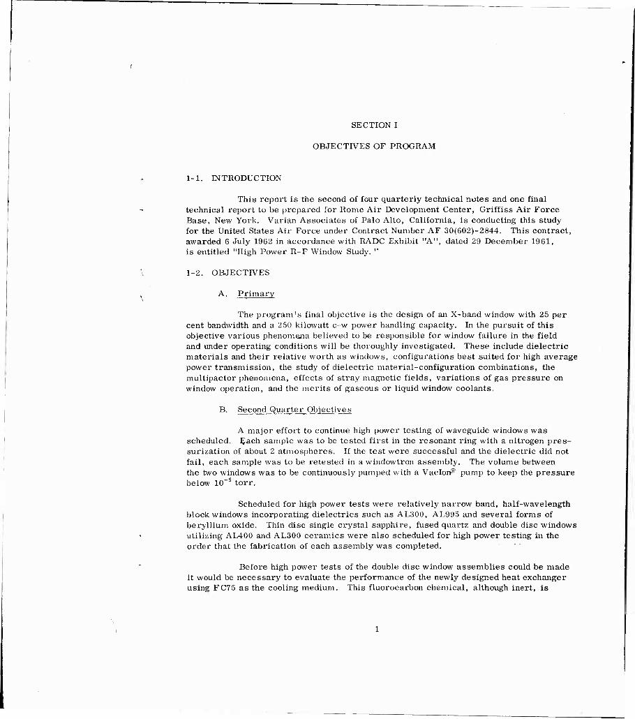
This report is the second of four quarterly technical notes and one final technical report to be prepared for Rome Air Development Center, Griffiss Air Force Base, New York. Varian Associates of Palo Alto, California, is conducting this study for the United States Air Force under Contract Number AF 30(602)-2844. This contract, awarded 6 July 1962 in accordance with RADC Exhibit "A", dated 29 December 1961, is entitled "High Power R-F Window Study. "
1-2. OBJECTIVES
A. Primary
The program's final objective is the design of an X-band window with 25 per cent bandwidth and a 250 kilowatt c-w power handling capacity. In the pursuit of this objective various phenomena believed to be responsible for window failure in the field and under operating conditions will be thoroughly investigated. These include dielectric materials and their relative worth as windows, configurations best suited for high average power transmission, the study of dielectric material-configuration combinations, the multipactor phenomena, effects of stray magnetic fields, variations of gas pressure on window operation, and the merits of gaseous or liquid window coolants.
B. Second Quarter Objectives
A major effort to continue high power testing of waveguide windows was scheduled. Each sample was to be tested first in the resonant ring with a nitrogen pres- surization of about 2 atmospheres. If the test were successful and the dielectric did not fail, each sample was to be retested in a windowtron assembly. The volume between the two windows was to be continuously pumped with a Vadorf51 pump to keep the pressure below ICT5 torr.
Scheduled for high power tests were relatively narrow band, half-wavelength block windows incorporating dielectrics such as AL300, AL995 and several forms of beryllium oxide. Thin disc single crystal sapphire, fused quartz and double disc windows utilizing AL400 and AL300 ceramics were also scheduled for high power testing in the order that the fabrication of each assembly was completed.
Before high power tests of the double disc window assemblies could be made it would be necessary to evaluate the performance of the newly designed heat exchanger using FC75 as the cooling medium. This fluorocarbon chemical, although inert, is

highly volatile and expensive so handling procedures must be determined for this particular application.
A continued effort was scheduled to determine methods of mechanically strengthening thin disc windows and cold testing these devices for broadband, ghost mode free operation. The more favorable results of such tests would then be used in the design and high power test of such windows in the ring resonator.
SECTION II
TECHNICAL PROGRESS OF PROGRAM
2-1. GENERAL DISCUSSION
A. Ring Calibration
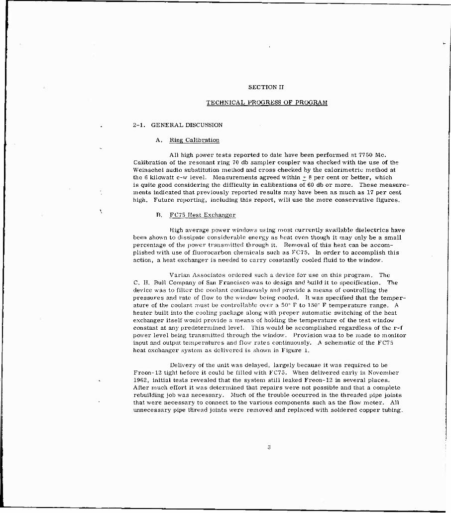
All high power tests reported to date have been performed at 7750 Mo. Calibration of the resonant ring 70 db sampler coupler was checked with the use of the Weinschel audio substitution method and cross checked by the calorimetric method at the 6 kilowatt c-w level. Measurements agreed within + 8 per cent or better, which is quite good considering the difficulty in calibrations of 60 db or more. These measure- ments indicated that previously reported results may have been as much as 17 per cent high. Future reporting, including this report, will use the more conservative figures.
B. FC75 Heat Exchanger
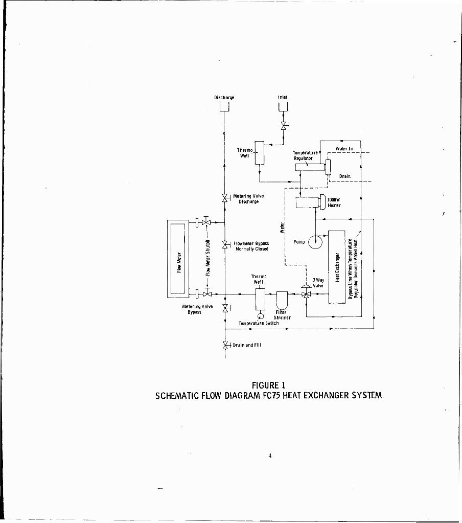
High average power windows using most currently available dielectrics have been shown to dissipate considerable energy as heat even though it may only be a small percentage of the power transmitted through it. Removal of this heat can be accom- plished with use of fluorocarbon chemicals such as FC75. In order to accomplish this action, a heat exchanger is needed to carry constantly cooled fluid to the window.
Varian Associates ordered such a device for use on this program. The C. H. Bull Company of San Francisco was to design and build it to specification. The device was to filter the coolant continuously and provide a means of controlling the pressures and rate of flow to the window being cooled. It was specified that the temper- ature of the coolant must be controllable over a 50° F to 150° F temperature range. A heater built into the cooling package along with proper automatic switching of the heat exchanger itself would provide a means of holding the temperature of the test window constant at any predetermined level. This would be accomplished regardless of the r-f power level being transmitted through the window. Provision was to be made to monitor input and output temperatures and flow rates continuously. A schematic of the FC75 heat exchanger system as delivered is shown in Figure 1.
Delivery of the unit was delayed, largely because it was required to be Freon-12 tight before it could be filled with FC75. When delivered early in November 1962, initial tests revealed that the system still leaked Freon-12 in several places. After much effort it was determined that repairs were not possible and that a complete rebuilding job was necessary. Much of the trouble occurred in the threaded pipe joints that were necessary to connect to the various components such as the flow meter. All unnecessary pipe thread joints were removed and replaced with soldered copper tubing.
Discharge
u Inlet
H14
ä ^ i
ThermoJ, Well
Temperature Regulator
Water In
y I Metering Valve Discharge
V-l Flowmeter Bypass ^ Normally Closed
H}*—; Metering Valve
Bypass
Drain
Pump
1000W Heater
Thermo Well
-V '• 3 Way
Valve «en
^ Filter
Strainer Temperature Switch
§
'■2 S
Drain and Fill
FIGURE 1 SCHEMATIC FLOW DIAGRAM FC75 HEAT EXCHANGER SYSTEM
Where threaded joints were necessary, a litharge and glycerin mixture was applied which, when hardened, formed leak-proof connections. All cast bronze valves were also removed and replaced with vacuum valves.
Once the system was rebuilt, it was tested tight up to 65 psi of Freon-12. Refrigeration people commonly determine if a freon system leaks by using a presto (acetylene) tank and torch with an attached short hose which sucks a little air (or air containing freon) up into the acetylene flame. If the flame changes color and grows larger, there is a leak in the joint at which the short hose is directed. Since FC75 and Freon-12 are chemically very similar, it was felt that such a test might be valid for FC75. An experiment subsequently showed that the acetylene torch method will work just as well with inert fluorocarbon systems.
C. Dangers of Beryllium Oxide
Although the work leading to the following report was not performed on this contract, it is felt of great enough significance to warrant mention here. Certain high power tests on beryllium oxide windows were made in Varian's "S" band resonant ring. During the course of the experiments one of the windows failed under very high power conditions. When the waveguide test setup was disassembled, a strong pungent.odor was detected. One short piece of the waveguide was submitted to the chemical labora- tory for analysis. The following report was returned. "A wipe test of the interior of the waveguide submitted was positive for beryllium. The quantity was 4 micrograms of beryllium; however, a wipe test is not a quantitative sampling and is not to be con- sidered an order of magnitude estimation of the amount present. "
In the interest of personnel safety, a number of filtered face masks have been ordered for use when testing beryllium oxide windows.
2-2. WINDOW CONSTRUCTION AND HIGH POWER TESTING
A. Single Thin Disc Fused Quartz Windows
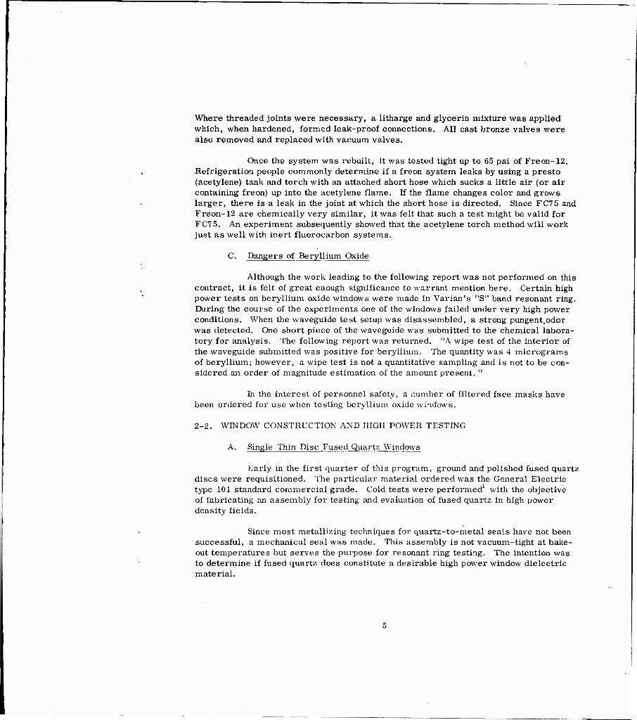
Early in the first quarter of this program, ground and polished fused quartz discs were requisitioned. The particular material ordered was the General Electric type 101 standard commercial grade. Cold tests were performed1 with the objective of fabricating an assembly for testing and evaluation of fused quartz in high power density fields.
Since most metallizing techniques for quartz-to-metal seals have not been successful, a mechanical seal was made. This assembly is not vacuum-tight at bake- out temperatures but serves the purpose for resonant ring testing. The intention was to determine if fused quartz does constitute a desirable high power window dielectric material.

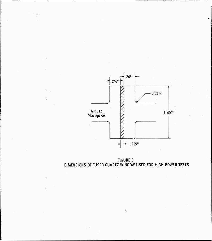
During this reporting period three assemblies, shown in Figure 2, were fabricated and tested in the ring resonator. The first was tested to failure at approxi- mately 70 kilowatts. At this power level, the dielectric melted near the center of the highest electric field density area as shown in the photographs of Figures 3 and 4. This is significant since fused quartz softens at approximately 1670° C and fuses at about 1800° C. The area where melting occurred had a diameter of approximately 0. 100 inch. Apparently the low thermal conductivity of the quartz body supports a high tem- perature gradient at the window center. Since the loss tangent of the body increases with temperature, * a mechanism is clearly provided for the observed thermal runaway phenomenon.
Further increase in power was not possible, since the high temperatures involved are believed responsible for causing a visually observed plasma discharge at the window face. Such a discharge has always been shown to mismatch the resonant ring to such a point that useful results are no longer obtainable.
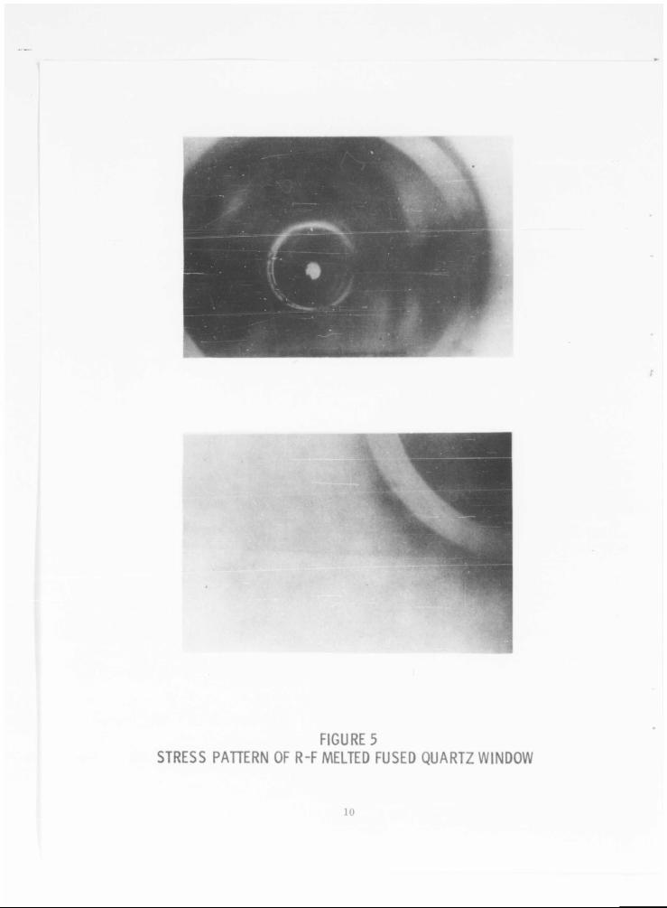
Figure 5 illustrates the stress pattern remaining in the vicinity of the melted area after cooling. Prior to the test, the stress pattern had been observed, under polarized light, to be negligible. Encasing the disc in a resin and grinding a cross- sectional view of the melted area revealed the pattern shown in Figure 6. Note the pin- point opening on the power output side.
As power in this test had been increased in lO-kilowatt steps until the window failed, and because failure occurred at an unexpectedly low level, insufficient data had been taken. A second window was fabricated, with the location of the larger bubbles within the quartz carefully noted. This window failed in the same manner as the first, but at 50 kilowatts cw. The observed sequence of visible effects leading to the window's failure was spectacular. As the power was slowly increased to the 50- kilowatt level, in approximately 5-kilowatt steps, no visual effects were seen. Once at 50 kilowatts for a few seconds, a small area near the center of the disc began to glow faintly with an orange color. Then it became brighter very rapidly to culminate in a very bright white flash of light. At this point the nitrogen in the ring ionized, de- tuning the ring and preventing further increase in power. The ionized atmosphere in the ring was violet in color.
Post test examination of the quartz showed a melted area similar to the first one, and that melting had not occurred at any of the previously observed larger bubbles. A photograph of that failure is shown in Figure 7. The cross section of the melted area was also very similar to that of Figure 6 with the pinpoint opening appear- ing on the power output side and not on the power input side. The significance of this, if any, is not clear at this time. Perhaps a very small bubble of air when heated to very high temperatures forces its way out of the quartz. With this in mind, another
See Quarterly Technical Note No. 1, Figure 2, p. 6.
WR112 Waveguide
FIGURE 2 DIMENSIONS OF FUSED QUARTZ WINDOW USED FOR HIGH POWER TESTS
FIGURE 3POWER INPUT SIDE OF FUSED QUARTZ WINDOW
SHOWING MELTED AREA
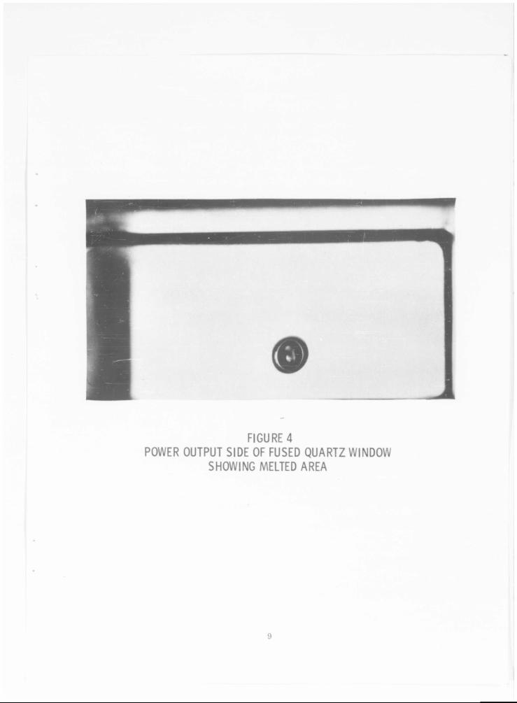
FIGURE 4POWER OUTPUT SIDE OF FUSED QUARTZ WINDOW
SHOWING MELTED AREA
-0
FIGURE 5STRESS PAHERN OF R-F MELTED FUSED QUARTZ WINDOW
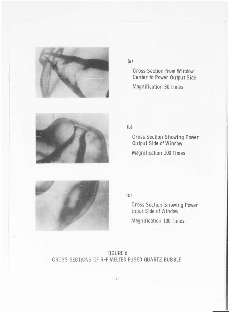
Cross Section from Window Center to Power Output SideMagnification 30 Times
(b)
Cross Section Showing Power Output Side of Window
Magnification 100 Times
Cross Section Showing Power Input Side of WindowMagnification 100 Times
FIGURE 6CROSS SECTIONS OF R-F MELTED FUSED QUARTZ BUBBLE
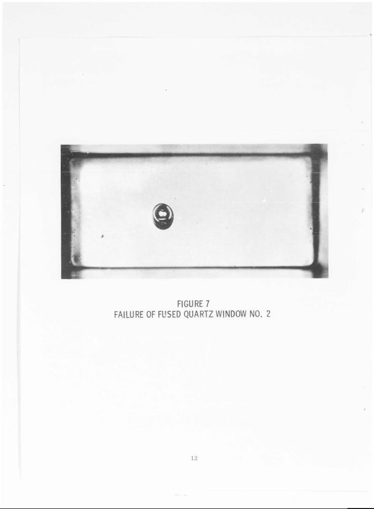
FIGURE?FAILURE OF FUSED QUARTZ WINDOW NO. 2
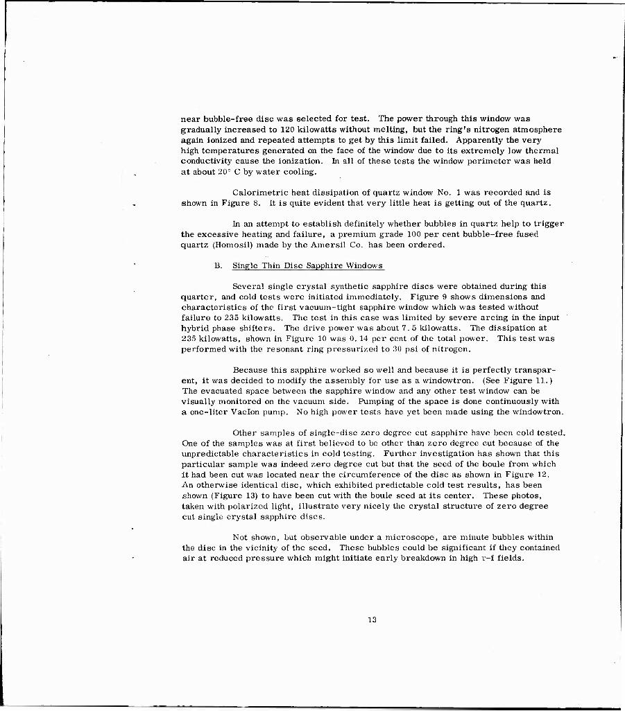
near bubble-free disc was selected for test. The power through this window was gradually increased to 120 kilowatts without melting, but the ring's nitrogen atmosphere again ionized and repeated attempts to get by this limit failed. Apparently the very high temperatures generated on the face of the window due to its extremely low thermal conductivity cause the ionization. In all of these tests the window perimeter was held at about 20° C by water cooling.
Calorimetric heat dissipation of quartz window No. 1 was recorded and is shown in Figure 8. It is quite evident that very little heat is getting out of the quartz.
In an attempt to establish definitely whether bubbles in quartz help to trigger the excessive heating and failure, a premium grade 100 per cent bubble-free fused quartz (Homosil) made by the Amersil Co. has been ordered.
B. Single Thin Disc Sapphire Windows
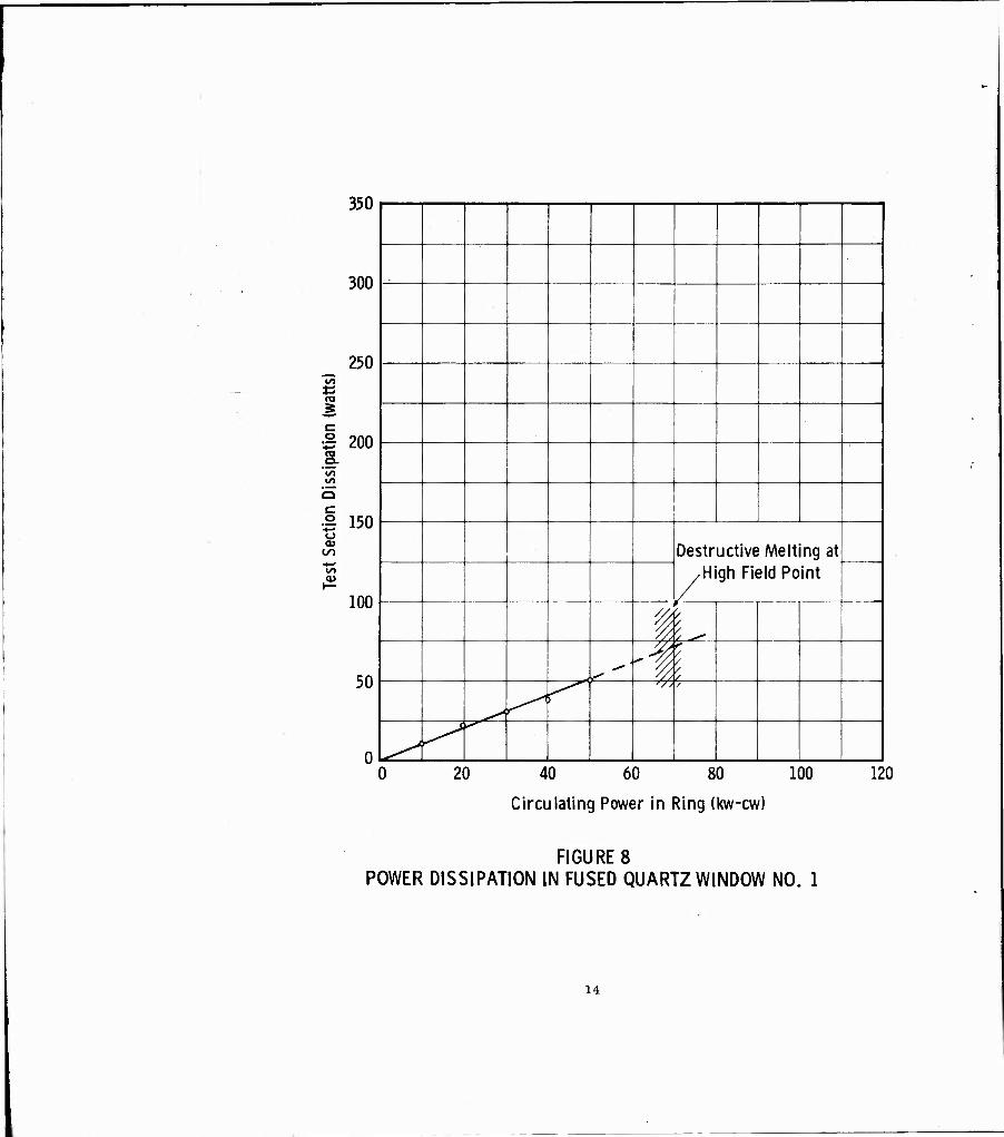
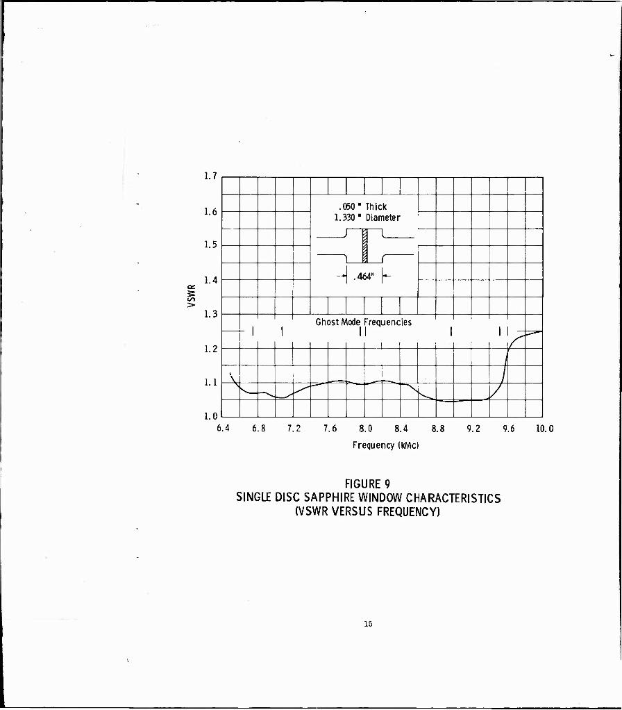
Several single crystal synthetic sapphire discs were obtained during this quarter, and cold tests were initiated immediately. Figure 9 shows dimensions and characteristics of the first vacuum-tight sapphire window which was tested without failure to 235 kilowatts. The test in this case was limited by severe arcing in the input hybrid phase shifters. The drive power was about 7. 5 kilowatts. The dissipation at 235 kilowatts, shown in Figure 10 was 0. 14 per cent of the total power. This test was performed with the resonant ring pressurized to 30 psi of nitrogen.
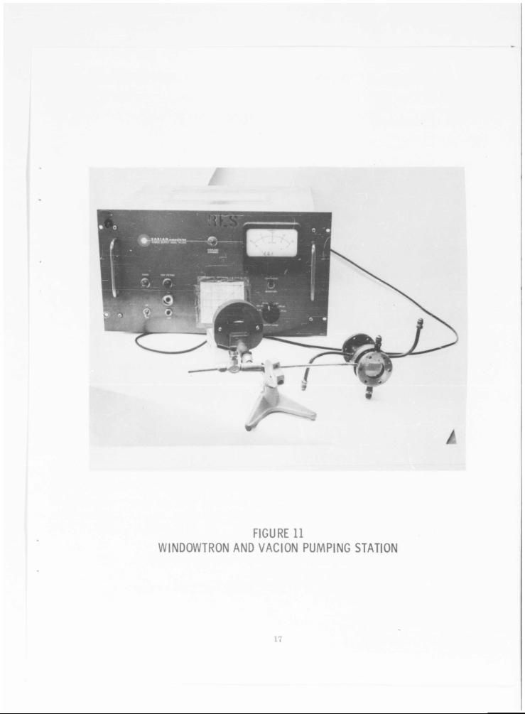
Because this sapphire worked so well and because it is perfectly transpar- ent, it was decided to modify the assembly for use as a windowtron. (See Figure 11.) The evacuated space between the sapphire window and any other test window can be visually monitored on the vacuum side. Pumping of the space is done continuously with a one-liter Vaclon pump. No high power tests have yet been made using the windowtron.
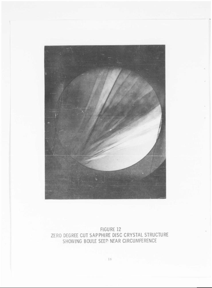
Other samples of single-disc zero degree cut sapphire have been cold tested. One of the samples was at first believed to be other than zero degree cut because of the unpredictable characteristics in cold testing. Further investigation has shown that this particular sample was indeed zero degree cut but that the seed of the boule from which it had been cut was located near the circumference of the disc as shown in Figure 12. An otherwise identical disc, which exhibited predictable cold test results, has been shown (Figure 13) to have been cut with the boule seed at its center. These photos, taken with polarized light, illustrate very nicely the crystal structure of zero degree cut single crystal sapphire discs.
Not shown, but observable under a microscope, are minute bubbles within the disc in the vicinity of the seed. These bubbles could be significant if they contained air at reduced pressure which might initiate early breakdown in high r-f fields.
13
350
300
250 to
I 200 a 'in ist
■2 150 o a>
to a>
100
50
Destructive Melting at • High Field Point
i </ /
,-' -1 / / / ^ f^
'// /
^ k^-*^
20 40 60 80 100
Circulating Power in Ring (kw-cw)
120
FIGURES POWER DISSIPATION IN FUSED QUARTZ WINDOW NO. 1
14
cc
1/1 >
1.7
1.6
1.5
1.4
1.3
1.2
1.1
1.0
.OSO" Thick 1.3 30" Dian leter
—»■
r .464"
1 1
-1 1 Ghost Mode Frequencies
i i i i i i i
i i r A /
r
V — v,
X ̂ ~\
6.4 6.8 7.2 7.6 8.0 8.4 8.8 9.2 9.6 10.0
Frequency (kMc)
FIGURE 9 SINGLE DISC SAPPHIRE WINDOW CHARACTERISTICS
(VSWR VERSUS FREQUENCY)
15
700
600
500 to
TO
•| 400
CO
•2 300 o 09
CO
200
100
^ O
40 80 120 160
Ring Power (kw)
200 240
FIGURE 10 POWER DISSIPATION IN SINGLE DISC SAPPHIRE WINDOW ASSEMBLY
16
#
FIGURE 11WINDOWTRON AND VACION PUMPING STATION
:;..it!?^^ S-'i P3®-'h...
'^Ji
FIGURE 12ZERO DEGREE CUT SAPPHIRE DISC CRYSTAL STRUCTURE
SHOWING BOULE SEEP NEAR CIRCUMFERENCE
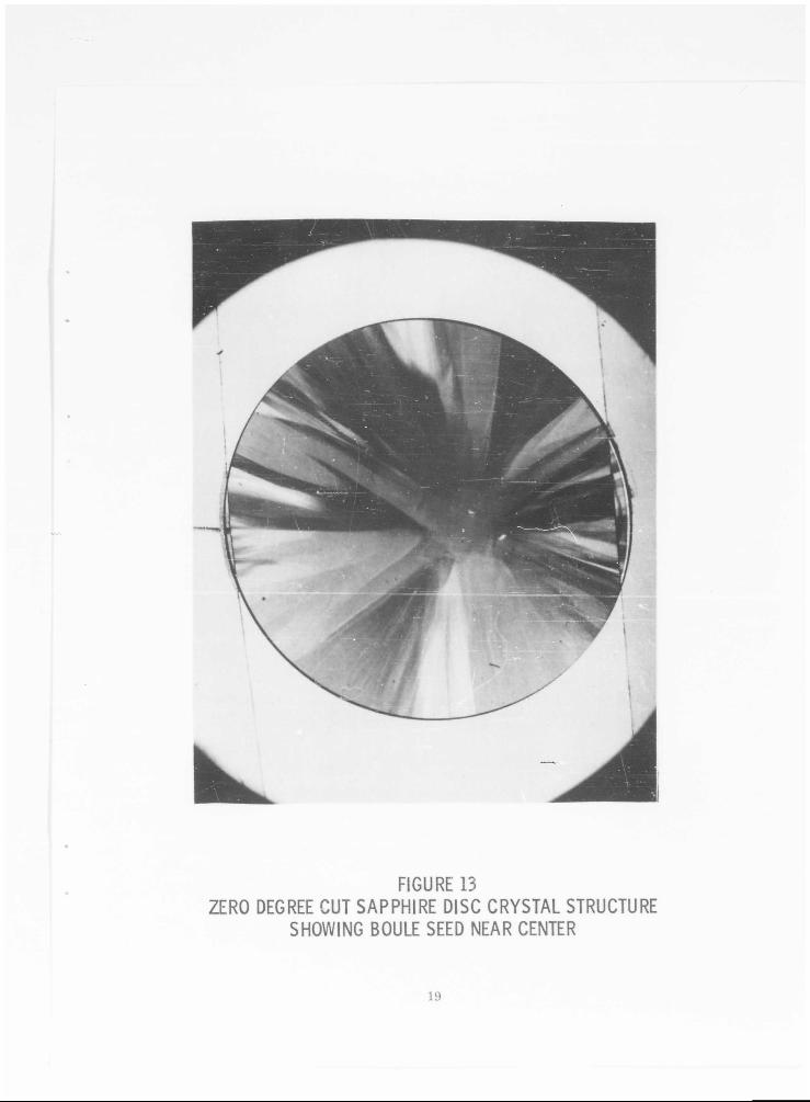
FIGURE 13ZERO DEGREE CUT SAPPHIRE DISC CRYSTAL STRUCTURE
SHOWING BOULE SEED NEAR CENTER
Very careful investigation has shown that early indications of electrical dissimilarities between zero degree cut sapphire discs cut from different portions of the boule were erroneous. The discs are identical and can be used interchangeably in any design.
C. Single Thin Disc Beryllium Oxide Windows
The fabrication of a circular thin disc beryllium oxide window has not yet been accomplished satisfactorily. The first attempt was not successful because the OFHC cylinder to which the disc is brazed developed a leak through the copper. New beryllium oxide discs have been received and cold tested. Metallizing of these discs is now in progress.
D. Double Thin Disc Windows
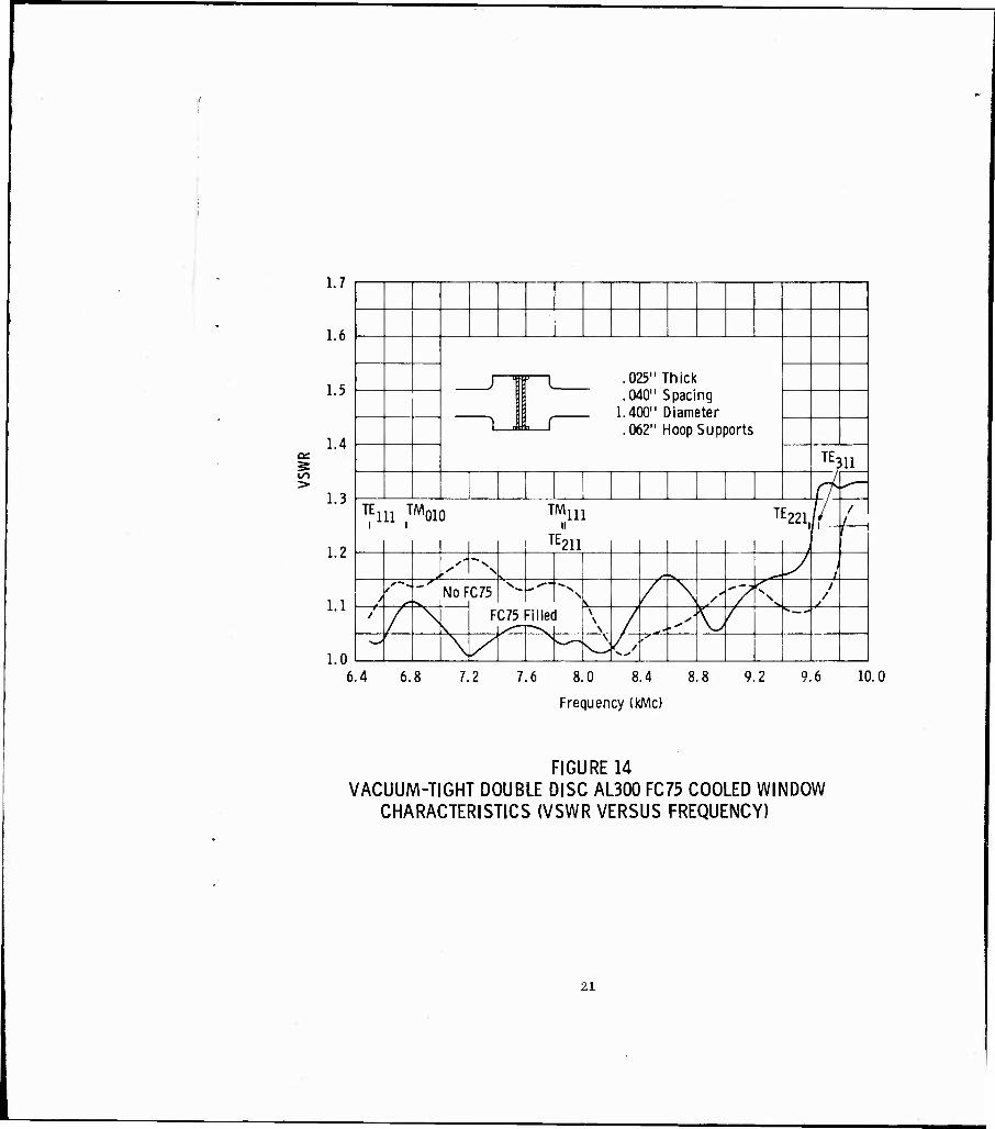
Two vacuum-tight double disc window assemblies were fabricated during this quarter. The cold test results from the first one completed are shown in Figure 14. The broken line shows the standing wave ratio versus frequency when the space between the windows is air filled. A relatively minor improvement is obtained when the assembly has FC75 between the discs. In either case the bandwidth is over 40 per cent with a VSWR under 1. 2. However, this does not take into consideration the resonant ghost modes which are present.
Cavity perturbation techniques were employed in exciting and identifying the modes shown in Figure 14. The maximum mode-free bandwidth is then reduced to 19. 6 per cent. Design tests on this window had indicated that a 0. 040 space between the dual discs would load the modes down to an undetectable level. Apparently the loss tangent of the Eccostock H20* is somewhat higher than quoted by the manufacturer. If this is so, the modes would be more greatly damped.
With greater mode damping (lowering of mode Q) in mind, another double disc window (this time using AL400 ceramic) was designed and fabricated with the window spacing doubled. Thicker discs of A1/400 were used to increase the window's strength. Not only does the greater thickness improve the strength but AL400 has a greater flexural strength than AL300. This, of course, was accomplished at the ex- pense of some bandwidth. Cold test results from the vacuum-tight AL400 window with FC75 between the discs are shown in Figure 15. No resonant ghost modes are detect- able in this window and the bandwidth is 33. 3 per cent.
The first experiment with the FC75 heat exchanger was to connect the AL300 dual disc window to it and circulate the fluid. Using the built-in heater, the tem- perature was raised slowly over a period of several hours to 65° C. During this cycle
See Quarterly Technical Note No. 1, pp. 26, 27.
20
IT) >
1.7
1.6
1.5
1.4
1.3
1.2
1.1
1.0
J
.11 r
.\ia micK
.040" Spacing 1.400" Diameter
1 —
. UUC 1 lUUp .PUppUl 13
TE311
ch ̂ -\
T,E111 ,™010 ™111 TE221.// f
I 1
1 1 _ ! TE211 1 i
f
, ̂ i"^ y •- s. 7 1
/ NoF ^ i
C75 v
i S \ / \ > 'TTN. / A \
s. FC7J Filled \ \
V / ,- 4
^ / r-""
^ \
\ \ M
6.4 6.8 7.2 7.6 8.0 8.4 8.8 9.2 9.6 10.0
Frequency (kMc)
FIGURE 14 VACUUM-TIGHT DOUBLE DISC AL300 FC75 COOLED WINDOW
CHARACTERISTICS (VSWR VERSUS FREQUENCY)
21

an
CO
1.1
1.6 1.400" Diameter .030" Thick .080" Spacing .062" Supporting Hoops
1
1.5
1.4 J { 1 1
___ 1.3 ~^ A, r
1.2 \ ' ' ' 1 1
33.3% BW 1 I
i i 1 -
\ S 1 _ _L._ 1111
1.1
V
s. "^ ^ ̂ ~ v /
i n ^N -^
6.4 6.8 7.2 7.6 8.0 8.4 8.8 9.2 9.6 10.0
Frequency (kMc)
FIGURE 15 VACUUM-TIGHT DOUBLE DISC AL400 FC75
COOLED WINDOW CHARACTERISTICS
22
the standing wave ratio across the frequency band was monitored continuously. No change in this response was noted. The fluid input lino pressure was slowly increased to 65 psi with no adverse affects upon the window. Unfortunately this window was accidently destroyed by excessive input line pressure when, inadvertently, the pressure- reducing valve was opened while the system was off. When the pump was switched on again for the next test, a surge of pressure fractured one of the discs. An estimate of this fracture pressure from calculation, and considering that the windows were rein- forced with hoops, indicate that it would have taken more than 100 psi input pressure to break the window.
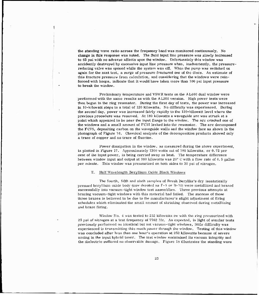
Preliminary temperature and VSWR tests on the AL400 dual window were performed with the same results as with the AL300 version. High power tests were then begun in the ring resonator. During the first day of tests, the power was increased in 10-kilowatt steps to a total of 120 kilowatts. No difficulty was experienced. During the second day, power was increased fairly rapidly to the 120-kilowatt level where the previous procedure was resumed. At 180 kilowatts a waveguide arc was struck at a point which appeared to be near the input flange to the window. The arc cracked one of the windows and a small amount of FC75 leaked into the resonator. The arc decomposed the FC75, depositing carbon on the waveguide walls and the window face as shown in the photograph of Figure 16. Chemical analysis of the decomposition products showed only a trace of copper and no trace of fluorine.
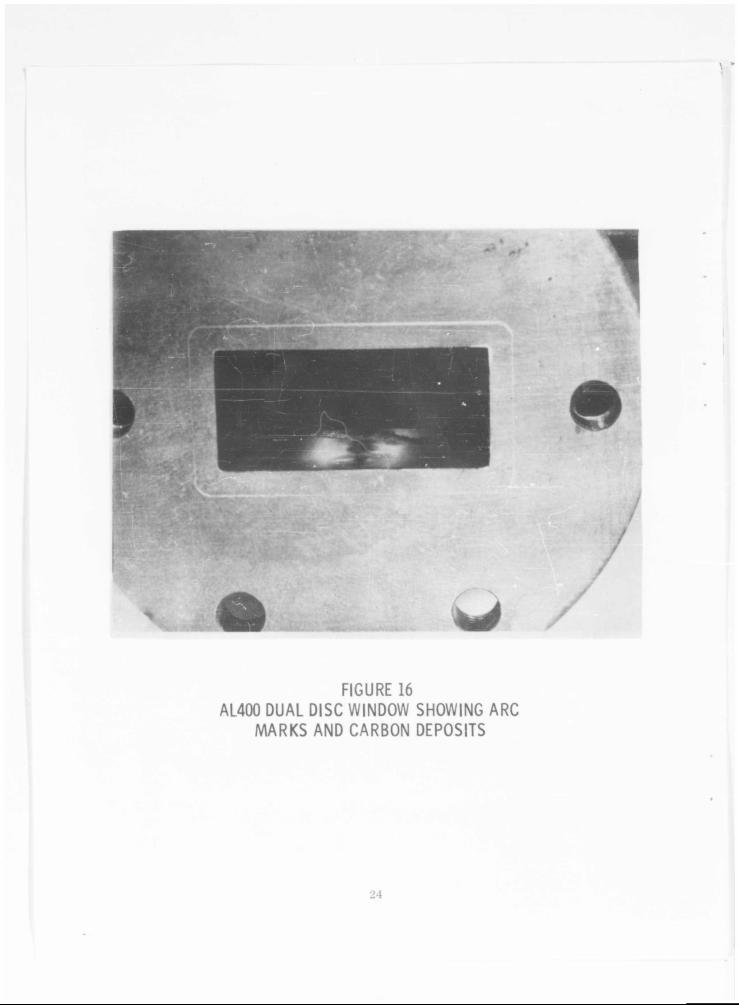
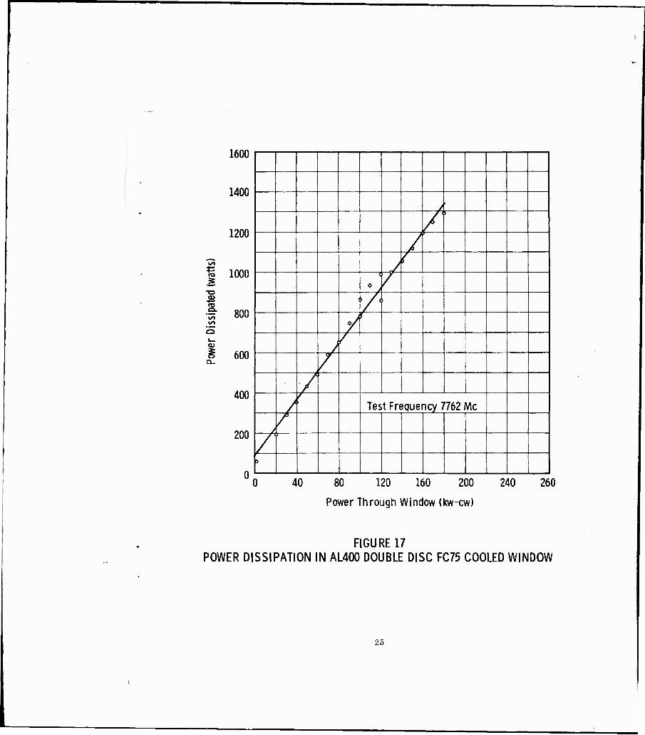
Power dissipation in the window, as measured during the above experiment, is plotted in Figure 17. Approximately 1300 watts out of 180 kilowatts, or 0. 72 per cent of the input power, is being carried away as heat. The temperature difference between window input and output at 180 kilowatts was 20° C with a flow rate of 0. 5 gallon per minute. This window was pressurized on both sides to 30 psi of nitrogen.
E. Half Wavelength Beryllium Oxide Block Windows
The fourth, fifth and sixth samples of Brush Beryllia's dry isostatically pressed beryllium oxide body (now denoted as F-l or B-10) were metallized and brazed successfully into vacuum-tight window test assemblies. Three previous attempts at brazing vacuum-tight windows with this material had failed. The success of these three brazes is believed to be due to the manufacturer's slight adjustment of firing schedules which eliminated the small amount of shrinking observed during metallizing and braze firing.
Window No, 4 was tested to 252 kilowatts cw with the ring pressurized with 25 psi of nitrogen at a test frequency of 7762 Mc, As expected, in light of similar tests previously performed on identical but not vacuum-tight windows, little difficulty was experienced in transmitting this much power through the window. Testing of this window was concluded after less than one hour's operation at 252 kilowatts because of severe arcing in the input hybrid tuner. The test window maintained its vacuum integrity and the dielectric suffered no observable damage. Figure 18 illustrates the standing wave
23
■ •*'-3.mmXJr--f
*■-
-.-yr
>'■ * fA ■'
.r.iiijB^
'ir
■ K-
•T*. ,
“yiH
FIGURE 16AL400 DUAL DISC WINDOW SHOWING ARC
IVIARKS AND CARBON DEPOSITS
24
1600
1400
1200
1000 S
■o
"^ 800 OO
o 1— <u g 600 Q-
400
200
0^
j
A 5
/
/ (
1
0 > /
■ r '
7^ r
j /
/
/
/
r Test Frequency 7762 v\c
/ /
/ D
0 40 80 120 160 200 240 260
Power Through Window (kw-cw)
FIGURE 17 POWER DISSIPATION IN AL400 DOUBLE DISC FC75 COOLED WINDOW
25

"V Nss^^
\ k 3
\
\ ft?
*—«
s:
\
jo
fe^ J
1 /
/ /
/ ^
/
/
/
-
>> er c
- —^ X
Test F
requ
(
7762
Mc
•&
u
oo I—
O
<
<
— ^ CD i oo o
^ O >-, Ll-I —1 o c OCL OQ
o- ID Uj
s U- "" >< o
>- LU
o
o < >
S? §
«MSA
26
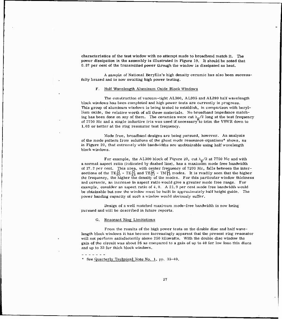
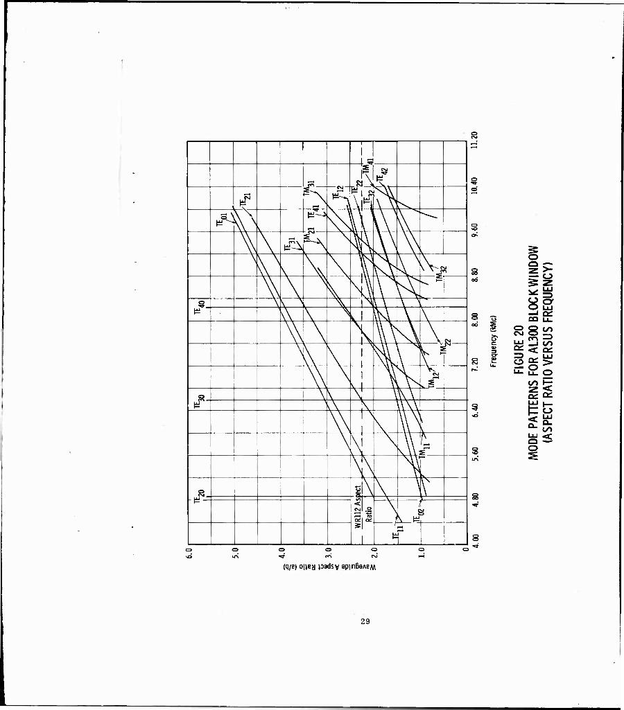
characteristics of the test window with no attempt made to broadband match it. The power dissipation in the assembly is illustrated in Figure 19. It should be noted that 0. 37 per cent of the transmitted power through the window is dissipated as heat.
A sample of National Beryllia's high density ceramic has also been success- fully brazed and is now awaiting high power testing.
F. Half Wavelength Aluminum Oxide Block Windows
The construction of vacuum-tight AL300, AL995 and AL399 half wavelength block windows has been completed and high power tests are currently in progress. This group of aluminum windows is being tested to establish, in comparison with beryl- lium oxide, the relative worth of all these materials. No broadband impedance match- ing has been done on any of them. The ceramics were cut A /2 long at the test frequency of 7750 Mc and a single inductive iris was used if necessary to trim the VSWR down to 1. 03 or better at the ring resonator test frequency.
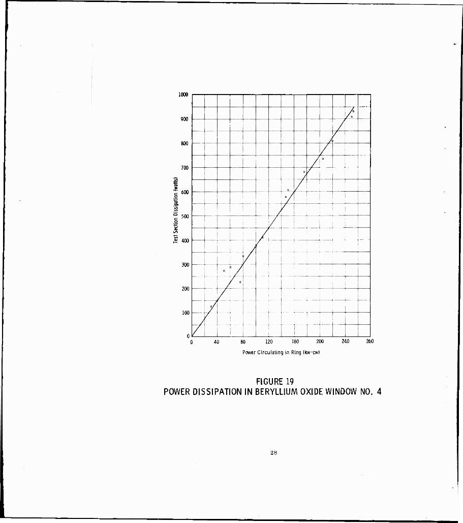
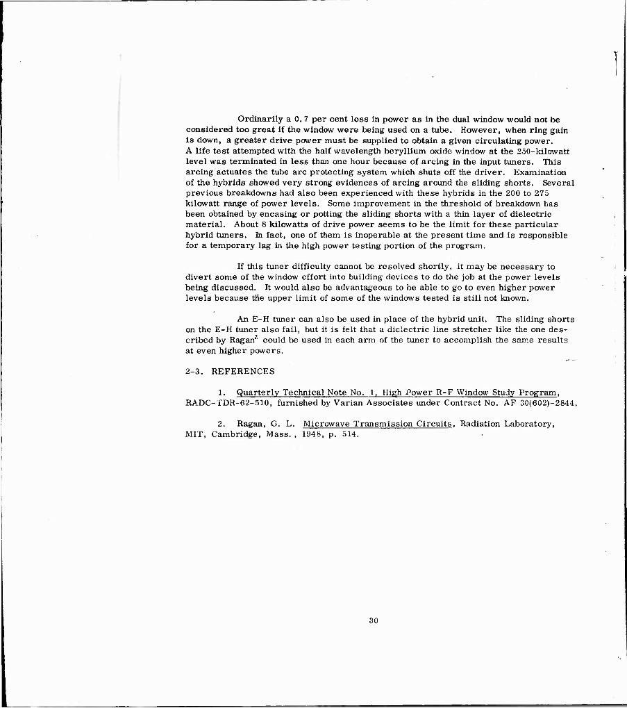
Mode free, broadband designs are being pursued, however. An analysis of the mode pattern from solutions of the ghost mode resonance-equations* shows, as in Figure 20, that extremely wide bandwidths are unobtainable using half wavelength block windows.
For example, the AL300 block of Figure 20, cut \„/Z at 7750 Mc and with a normal aspect ratio (indicated by dashed line), has a maximum mode free bandwidth of 17.2 per cent. This area, with center frequency of 7200 Mc, falls between the inter- sections of the TE3^) - TE^ and TE^ - TMfi modes. It is readily seen that the higher the frequency, the higher the density of the modes. For this particular window thickness and ceramic, an increase in aspect ratio would give a greater mode free range. For example, consider an aspect ratio of 4. 0. A 21. 9 per cent mode free bandwidth would be obtainable but now the window must be built in approximately half height guide. The power banding capacity of such a window would obviously suffer.
Design of a well matched maximum mode-free bandwidth is now being pursued and will be described in future reports.
G. Resonant Ring Limitations
From the results of the high power tests on the double disc and half wave- length block windows it has become increasingly apparent that the present ring resonator will not perform satisfactorily above 250 kilowatts. With the double disc window the gain of the circuit was about 26 as compared to a gain of up to 40 for low loss- thin discs and up to 33 for thick block windows.
See Quarterly Technical Note No. 1, pp. 33-40.
27
1000 r
900
800
700
1 600
500
^ 400
300
200
100
—i
/
/
/
/
/ 0
0 /
1 o
i
/
o /
1 { 1
i i j/ 1 i
—— — A 1
3 /
/ _.. .
III
1 i I
0 ) / 1 i 1
■ ; J f 0
r 1
—Y i
\
/ — 1 1
/ --/■
. i i i : 1 LJ / 1
/ i 40 80 120 160 200 240 260
Power Circulating in Ring (kw-cw)
FIGURE 19 POWER DISSIPATION IN BERYLLIUM OXIDE WINDOW NO. 4
28
—i
^ CM —
R1 i tu
^ v^^
^N s. ^
\^ Oy v ^
\ \
i-H m ^ V
\
V N \\ \ \\ \M \ \ Ai
\ \ \
V HY \ ^A ^^ t—
i § \ N \ i \ \ \ v
e \\ \ \ s.1 UH \ \
\\ l\ \ w \\ \ 1 Ri
\ \ \
r 1 ^ \ I'
\\ , \ i v i V ̂
V
& \ \ "T \\\ £ "^ A s \\\\
\\ I s I \ V
\ \l \
\ N \ \\i—
s_ i \ \ V h^ — < o
"TO ct: \ s ^
S
§
3 — o oo
82 s -o CQ UL. oo i O 8^
r? C^ —' c UJ _J CO 3 Q£ < Ql cr 3 ■ ■ i
S
RNS
FOR
RATI
O V
5
DE P
ATTE
(A
SPEC
T
CD o
8
(q/E) oiiey padsy apmBaAB^
29
Ordinarily a 0. 7 per cent loss in power as in the dual window would not be considered too great if the window were being used on a tube. However, when ring gain is down, a greater drive power must be supplied to obtain a given circulating power. A life test attempted with the half wavelength beryllium oxide window at the 250-kilowatt level was terminated in less than one hour because of arcing in the input tuners. This arcing actuates the tube arc protecting system which shuts off the driver. Examination of the hybrids showed very strong evidences of arcing around the sliding shorts. Several previous breakdowns had also been experienced with these hybrids in the 200 to 275 kilowatt range of power levels. Some improvement in the threshold of breakdown has been obtained by encasing or potting the sliding shorts with a thin layer of dielectric material. About 8 kilowatts of drive power seems to be the limit for these particular hybrid tuners. In fact, one of them is inoperable at the present time and is responsible for a temporary lag in the high power testing portion of the program.
If this tuner difficulty cannot be resolved shortly, it may be necessary to divert some of the window effort into building devices to do the job at the power levels being discussed. It would also be advantageous to be able to go to even higher power levels because the upper limit of some of the windows tested is still not known.
An E-H tuner can also be used in place of the hybrid unit. The sliding shorts on the E-H tuner also fail, but it is felt that a dielectric line stretcher like the one des- cribed by Ragan?' could be used in each arm of the tuner to accomplish the same results at even higher powers.
2-3. REFERENCES
1. Quarterly Technical Note No. 1, High Power R-F Window Study Program, RADC-TDR-f>2-510, furnished by Varian Associates under Contract No. AF 30(602)-2844.
2. Ragan, G. L. Microwave Transmission Circuits, Radiation Laboratory, MIT, Cambridge, Mass. , 1948, p. 514.
30

SECTION III
FISCAL STATUS OF PROGRAM
The rate of expenditure on the High Power R-F Window Study Program during the quarter has been approximately $5, 900 per month. This Includes about $168 per month spent on materials and supplies for window construction. There were 1645 man-hours expended during the second quarter.
Estimated expenditures for the remainder of the program are $4, 600 and 390 man-hours per month.
31
SECTION IV
PROGRAM FOR NEXT QUARTER
During the coming quarter all windows previously tested successfully in the resonant ring will be retested in a windowtron assembly. The windowtron will be evacuated between the transparent sapphire disc and the window being tested. Included in these tests will be high density beryllium oxide from two different manufacturers, AL995 and AL300. The alumina blocks will be pretested in a nitrogen atmosphere for direct comparison with their beryllium oxide counterparts. The performance of the various block windows will then be analyzed to find which material, if any, is prefer- able for construction of even higher power windows.
Additional double disc windows will be fabricated and tested to verify the experimental results from the AL400 version. Certain other double disc designs now in various stages of cold testing will be pursued further to improve power handling capacity at the possible expense of bandwidth.
It is anticipated that the windowtron will also be used as a device to measure the effects on power handling of small variations in gas pressure in the 10-4 to 10~8
torr range. Methods of inducing multipactor and the phenomenon of multipactor in general will be studied using the windowtron.
Since there has been difficulty with breakdown at the sliding shorts of the hybrid phase shifters, some effort will be made this coming quarter to improve the present upper limit of power circulating in the ring resonator.
32
Contract No. AF 30(602)-28Ü Virian Associates
Quarterly Technical Note No. 1 October - 31 December 1962
DISTRIBUTION LIST
Copy No No. of Coplea Address
**RADC (RALTP, ATTN: D. Busaey) Griffisa AFB NY
*RADC (RAAPT) Grlfflss AFB NY
*RADC (RAALD) Grifflas AFB NY
*GEEIA (ROZMCAT) Grifflas ABF NY
*RADC (RAIS, ATTN: Grlfflss AFB NY
US Army Electronics R and D Labs Liaison Officer RADC, Grlfflss AFB NY
Copy No.
32
No. of Copies Address
Commander Naval Missile Center Tech Library (Code NO 3022) PC Mugu Calif
Bureau of Naval Weapons «aln Navy Bldg Wash 2 5 DC ATTN: Tethnlcai Librarian, DLl-3
Redstone Scientific Information Center US Army Missile Command Redstone Arsenal, Alabama
CommandanC Armed Forces Staff College (Library) Norfolk 11 VA
*AIIL {3T) Maxwel1 AFB Ala
ASD (ASAPRD) Wright-Patter n AFB Ohio
rch Lab Chief, Naval Res ATTN: Code 2027 Wash 2 5 DC
Air Force Field RepresentatIv n«v«l Research Lab ATTN: Cede 1010 Wash 2 5 DC
Commanding Officer US Army Electronics R and D L ATTN: SELRA/SL-ADT Ft Honmouth NJ
utlcs and Space
h Center
National Aero Admin
Langley Resea Langley Station Hampton VUglnl ATTN: Llbraria
Central Intelligence Agen ATTN: OCR Mall Room 2^30 E Street NW
AFFTC (FTOOT) Edwards AFB Calif
US Naval Ordnance Lab (Tech Lib) White Oak, Silver Springs Md
Commanding General White Sands Missile Range New Mexico ATTN: Technical Library
Director US Army Engineer R and D Labs Technical Documents Center Ft Belvolr VA
ESD (ESRL) L G Hanscom Fid Bedford Mass
Commanding Officer and Director U.S Navy Electronics Lab (LI3) San Diego 52 Calif
ESD (ESAT) L G Hanscom Fid Bedford Mass
Llbrarv
US Strike Command ATTN: STRJ5-OR Mac Dill AFB Fla
AFSC (SCSE) Andrews AFB Wash 2 5 DC
Commanding General US Army Electronic Pr ATTN: Technical Docu Ft Hnachuca Ariz
*ASTIA {TISIA-2) Arlington Hall Statio Arlington 12 Vn
AFSC (SCFRE) Andrews AFB Wash 2 5 DC
Hq USAF (AFCOA) Wash 2 5 DC
AF0SR (SRAS/Dr. G. R. Ehe Ho 11oman AFB NMex
Office of Chief of Naval Operation (Op-724)
Navy Dept Wash 25 DC
Commander US Naval Air Dev Cen (NADC Lib) Johnsvllle Pa
College (Library) rracks Pa
APGC (PGAPI) Eglln AFB Fla
AFSWC (SWOI) Klrtland AFB NMe:
Litton Industries 960 Industrial Road San Carlos Calif
Mr. Del Churchill Sperry Gyroscope Co Great Neck NY
ARPA ATTN: Col Lindsay Washington 25 DC
RTD (RTGS) Boiling AFB Washington 25 DC
Dr. Louis R, Bloom Sylvanis Elect Prod Inc Physics Lab 208-20 WllletCs Point Blvd Bayslde, Long Island NY
♦Mandatory
**ProJect Engineer his symbol and
HI '»ueqan q»! qoJHBBay 8u3 IB^T-iiaaia
870U-[T11 jo X:nBjaA-nin
Xacncioqei aqn,i uoaasa^a 03 TJBJ3J1V 8aq8nH
M3nw '1 T 'JW
^atU «an 'XpBiDauaqDS ■ItouM »Ml
qin qajBasay jo AfQ sqni ucujaata 03 33313 1BI»U»O
anq:av 3W 'Q '3 '^
ep-jjoi j ' BmAHU-JBS epfiöij jo AqieaaA^un
8u3 iBD-jjiaaia jo nd»Q
BTu-iojnB3 "OJIV "l^d XBM U08UBH 119
B33B130fiBV UBT^BA uijav pJBUJaa 'Ju
UlUiOJUBD ' pJOJUB3S qo'j aAwmoj.ijvj
X3iBJ»Aiun pJojuB^s rtojopoqa "w -JQ
BpllOxi ' aiUAsau-jBo "■10 ^q"! 3=313 djoo /;.ijads
sjaf na« 'UOBTJJBH
aJiS 4^ qafios ^iv MQ aqiii 33^13 V3H
SSBK 'uo^ini-ina qBT Jaauads
03 9jH uoaqjX^tj qaiai 'M -JK
■SSBW 'uOTiSuHjng py »PISXBM
jcaqiXcy q»l aaauadc
JTTB0 03TV OT»d XBM UBBUBH XX9
BaiBiaoBev UBfjBA ouaaow pal '^H
Jt\*0 'BOTJBO UBS psoa iB^Jitnpui 096
iaTJSB^pui uoaqn XaBiqTl iBOTuqoai
3TTB3 'to-tJBD UBS pBoa iBTJ^snpui 096
8aij:snpui ooiati uoea»tt uiBitiTM '*a
B1UJO3TT»D '«»TA '^W BAV u/taAS 005 qBT 3qnx
aABwoa^TH BJUBAIXS iaaani) -a -9 -y -ZQ
8IUJ0311B3 '«aiA uiBaunow anusAV uXiaAg 0O9
BuofaHjado a^lASQ aABwoa^TW 3UI pOJd 30313 BABrtOaOfH
etUBqiunod ajopoaqj. "^W
HfUJOj-JiBD 'X^lD jaAina
OZ-W'W S9E1/0; ■jf 'eaaso -a "l -JK
030« -v Jaaaj -aw : NHV XaflJaf n3[j 'UTH XBJJUW
03 safiaanpui isaiaioaia
auB>( -a ■.IH :HX1V BiuaojiiBD 'oiiv oi»d jaa^as iBiaaauuuoa 599 ■ qsq «iiTJaaui8u3 auB)i
HJOA M»N 'BJluia •79 Z XCS Od
dJOD 33313 aBnoqSu-jasaft UBTJBjqn Sug
Sui^ "S uapiaqs 'JW
uoaSuiqBBM '(, 9l33B»s Su-jjaauiSua 333i3 jo 3d»Q
uoaSuiqsBfi 30 XaieaaA-jun uosijasH '3 'V MH
auooa 'W '3 'jo-id -HLVi "IMO '01 B"qui'".i03
BuijaauiSua 33313 jc jdBQ Xaifi-tsAiun aasss ^mo
Biuaoj-n«3 '031V 01"<I aasjig jjodsuBji i^o-?
djOD B3i;uoj33ai3 aABnojaiw las-JBX "J 'S 'iQ
BW ' U oiifuix
XjoiBJOqBT uioDun "X'l'W UBiuinfl ■» 'JW
pUBiXaFH ■; ajoiuniBfl XaoiBjrqoq uonBTpBa
X^isjaAiun BUiiidöH Buqor
■«.101 na« ' aisdaainiSnoi V9i n mooa 10: 8PI9
XjoaBJoqB'] qaJBasajj WSI toqog Pioann -aci
BlUJüJUBO 'O^IV OlBd aAv BIUJO]!^^ IO'I
BT aABnojajw ^3»13 isjauan aaqqan 'g ■j^
A. is Sf MftN -Xsiinn joiHumBBM 009 1 aiai iBjapaa
BIUJO311B3 '«aiA '^H anuaAV uXiSAa 00S
q»! aqnx aABnOJOiw BlUBAiXg uBuipoog 'Q ' JQ
Bd 'jaasBouBT
JBAOOH "W "JtW
opBJoioD 'uapioo 03 uTBiaaaoj »1003
qjasasaa }o joasaiiQ BJTJaaa "3 "3 '^W
XjBjqn qnaBasay aa33aA "U Bna3S ^NXIV
»tuJU>jTH»0 ' BOIJBS UBS Xan iBiasBnpul 106
3Ui qSnonno 3W 13313
auoiBuqof uqof :NXXV Xasjaf «3M 'urtoauoasa
UOlB-JA-fQ Mu»fl P^H etao3 UD13»IAV jqpuag
aoBUBM 'H aaajaAa :NX1V Jfl»^ 'XaT3 JBAino 03 3.JBJJJ-JV saqSnH
•PH 'aaouiTaisa 9^^ «OH aaodJiv !3"1 d-jqspuaua dJ03 3Jai3 3Bnoq9uia83rt
3daa qojBasa» panddv uoiaoas aqni aABrtoaa^n
JÄH 'uiaiH PIBaao "JW
njil t'S 'JUi qanouna aw-I33T3
aea^aa PIBUOQ 'JH
Hjo^ man 'B3Bq3I Bug aoaia 30 adaa
XaisaaAiun 113^^03 uBiuiBG -3 -aw
ssaappv saidoo 30 ON -on Xdoo
(•3uo3> isn Noiniai>iisia
■1uaojn»3 '03iv oiBd 03 UOBUqof BUl^B« saaaqoy -y 'T 'JQ
BTUaO3TlB0 '031V OlBd XB« UBBUBH 119
BBaBISOBBV UBIABA XjBJqn iB3luq33i
«■aappv eafdos jo rÖH 'on Ado^
2961 Jaqiusaaa lt - JiaqoaX) l Z -on 330N iBaiuqaax Kijaaasno
BaaBiiosev UBI-I"A
W9Z-iZ09)0i iV 'ON a3BJ3U03
Contract No. AF 30(602)-2844 Varlftn Aiioclmtes
Copy No. No. ot Coplti Addran
Quarterly Technical Note No. 2 I October - 31 December 1962
DISTRIBTUION LIST (Cont.)
Copy No. No. of Coptea
52 - 53 Technical Library Varian Aaaoclatee 611 Haneen Wey Palo Alto, California
Dr. L. A. Roberta Watklns Johnaort Co Palo Alto, California
Mr. Gerald Klein, Mgr Microwave Tube Section Applied Research Dept WeatinghouB-a Elect Corp Friendship Incl Airport Box 746 Baltimore, Md.
Hughes Aircraft Co Culver City, Calif ATTN: Everett M. Wallace
Sendix Aviation Corp Red Bank Division Eatontown, New Jersey AtTN: John Johnatone
Eitel Mc Cullough Inc 901 Industrial Way San Carlos, California ATTN: Stella R. Vetter Research Library
Mr. F, E. Ferrira Director of Research Coors Porcelain Co Golden, Colorado
Hr. H. Hoover RCA Lancaster, Pa
Dr. D. Goodman Sylvanta Microwave Tube Lab 500 Evelyn Avenue Mt. View, California
Mr. A. E. Harrison Univeralty of Washington Dept of Elect Engineering Seattle 5, Washington
Mr. Shelden S. King Eng Librarian Westinghouse Elect Corp PO Box 2S4 Elmlra, New York
Kane Engineering Labs 845 Commercial Street Palo Alto, California ATTN; Mr. P. Kane
Electrical Industries Co Murray Hill. New Jersey ATTN: Mr. Peter A. Muto
Mr. L. E. Gates, Jr. 20/1365 ül-*8-20 Hughes Aircraft Co Culver City, California
Mr. Theodore Poumbanis Microwave Elect Prod Inc Mlcrownve Device Operations hOO Evelyn Avenue Mountain View, California
Dr. R. G. E. Huttev Sylvanl.-' Microwave Tube Lab 500 Evelyn Ave Mt. View, California
Dr. William Watson Litton Industries 960 Industrial Road San Carlos, Calif
Technical Library Litton Industries 960 Industrial Road San Carloa, Calif
ddreas
Mr. C, Dalman Cornell University Dept of Elect Eng Ithaca, New York
Mr. Donald Priest Eltel-Mc Cullough Inc San Bruno. California
Mr. T. Marchese Federal Tele Labs Inc 500 Washington Ave Nutley, New Jersey
Mr. S. Webber General Elect Microwave Lab 601 California Ave Palo Alto, California
Dr. Harold Sobol IBM Research Laboratory Bldg 701 Room W 164 Poughkeepsle, New York
Dr. Kin Johns Hopkins University Radiation Laboratory Baltimore 2, Maryland
Mr. R. Butman M.I.T. Lincoln Laboratory PO Box 73 Lexington 73. Maas.
Dr. S. F. Kaisel Microwave Electronics Corp -061 Transport Street Palo Alto. California
Ohio State University Dept of Elect Engineering Columbus 10, Ohio ATTN: Prof. E. H. Roone
Mr. Bro
Mr. Ted Moreno Varian AbüCclä 611 Hanaen Way Palo Alto, Calif
Spencer Lab Raytheon Mfg Co Wayside Rd Burlington, Mass,
Mr. W. Teich Raytheon Mfg Co Spencer Lab Burlington, Mass.
Mr. Hans Jenny RCA Elect Tube Dlv 415 South 5th Street Harrison. New Jersey
Mr. P. Bergman Sperry Corp Elect Tube Dlv Gainesville. Florida
Dr. M. Chodorow Stanford University Microwave Lab Stanford, California
Dr. Bernard Arfln Varian Associates 611 Hansen Way Palo Alto, California
Dept of Electrical Eng University of Florida Galnsville, Florida
Dr. E. D. Mc Arthur General Elect Co Electron Tube Dlv of Researcl The Knolls Schenectady. New York
Mr, J. T. Mllek Hughes Aircraft Co Electron Tube Laboratory Tulver City, California
Univeralty of Illinois Electrical Eng Research Lab Urbana, 111 ATTN: Technical Editor
£C
Contract No. AF 30(602)-28^4 Varlan Associates
Quarterly Technical Note No. 2 1 October - 31 December 1962
Copy No
1
2
No. of Copies Address
**RADC (RALTP, ATTN: D, Busaey) GrlfflsB AFB NY
*RADC (RAAPT) Grtffias AFB NY
*RADC (RAALD) GrlffUa AFB NY
*GEEIA (ROZMCAT) Grlfflss ABF NY
*RADC (RAIS, ATTN: Mr. MaUoy) GrLfflsa AFB NY
US Army Electronics R and D Labs Liaison Officer RADC, Grifflas AFB NY
*AUL (3T) Maxwell AFB Ala
ASD (ASAPRD^ Wright-Patterson AFB Ohio
Chief, Naval Research Lab ATTN; Code 2027 Wash 2 5 DC
Air Force Field Representative Naval Research Lab ATTN: Code 1010 Wash 2 5 DC
Commanding Officer US Army Electronics R and D Labs ATTN: bELRA/SL-ADT Ft Monmouth NJ
DISTRIBUTION LIST
Copy No. No. of Copies Addrea
) 32 1
and Space National Aeron Admin
Langley Research Center Langley Station Hampton Virginia ATTN: Librarian
Central Intelligence Agency ATTN: OCR Mall Room 2A30 E Street NW Wash 2 5 DC
US Strike Command ATTN: STRJ5-0R Mao Dill AFB Fla
AFSC (SCSE) Andrews AFB Wash 2 5 DC
Commanding General US Array Electronic Proving Ground ATTN: Technical Documents Library Ft Huachuca Ariz
*ASTIA (TISIA-2) Arlington Hall Station Arlington 12 Va
AFSC (SCFRE) Andrews AFB Wash 25 DC
Hq USAF (AFCOA) Wash 25 DC
AFOSR (SRAS/Dr. G. R. Eber) Holloman AFB NMex
Office of Chief of Naval Operations (Op-724)
Navy Dept Waah 23 DC
Commander US Naval Air Dev Cen (NADC Lib) Johnsvllle Pa
Commander Naval Missile Center Tech Library (Code NO 3022) Pt Mugu Calif
Bureau of Naval Weapons Main Navy Bidg Wash 2 5 DC ATTN: Technical Librarian, DLl-3
Redstone Scientific Tj. formation Center US Array Missile Command Bedstone Arsenal, Alabama
Commandant: Armed Forces Staff College (Library) Norfolk 11 VA
ADC (ADOAC-DL) Ent AFB Colo
AFFTC (FTOOT) Edwards AFB Calif
US Naval Ordnance Lab (Tech Lib) White Oak, Sliver Springs Md
Commanding General White Sands Missile Range
Technical Llbr
jtrector US Army Engineer R and D Labs Technical Documents Center Ft ßelvoir VA
ESD (ESRL) L G Hanscora Fid Bedford Mass
Commanding Officer and Director US Navy Electronics Lab (LIB) San Diego 52 Calif
ESD (ESAT) L C Hanscom Fid Bedford Mass
Commandant US Army War College (Library) Carlisle Barracks Pa
APGC (PGAPI) Eglln AFB Fla
AFSWC (SUOI) Kirtland AFB NI .x
Dr. A. Pronner Litton Industries 960 Industrial Road San Carlos Calif
Mr, Del Churchill Sperry Gyroscope Co
ARPA ATTN; Col Lindsay Washington 25 DC
RTD (RTGS) Boiling AFB Washington 25 DC
Dr. Louis R. Bloom Sylvanla Elect Prod Inc Physics Lab 208-20 Willetts Point Blvd Bayslde, Long Island NY
*Mandato
■^Project

Contract No. AF 30(602)-2844 Varlan Asaoclatei
Quarterly TechnicsL Note No. 2 1 October - 31 December 1962
Copy 1 of Cople» Addvest
DISTRIBUTION LIST (Cont.)
Copy So. Nr>, of Coplei Addreaa
Dr. Norman Moore Litton Industrlea 960 Industrial Road San Carlos, California
Mass Institute of Technology Research Laboratory of Electro: Cambridge 39, Mass. ATTN: Document Library
University of Minnesota Minneapolis, Minnesota ATTN: Dr. W. G. Shepherd Dept of Elect Eng
Dr. M. Ettlnberg. Polytechnic Institute of Brooklyn Microwave Research Inat Brooklyn 1, New York
Mr. Job M. Osepchuk Raytheo Co Spe ncer Lab Bur ling on. Ma a
Dr. Bernard Hershenon RCA Lab Prl icetc n, New Jersey
Dr. W. M. Webster Director Electronic Research Lab RCA Labs Princeton, New Jersey
Stanford University Elect Research Laboratory Stanford, California ATTN: Mr. D. C. Bacon Asst Director
Dr. D. A. Watklns Stanford University Electronics Laboratory Stanford, California
Secretariat Advisory Group on Electron Tubes 346 Broadway New York 13, New York
Bell Telephone Ltbs Murry Hill Laboratory Murry Hill, New Jersey ATTN: Dr. J. R. Pierce
Mr. A. G, Petter Research Laboratories Div The Bendlx Corporation Southfleid Detroit, Michigan
Professor R. M. Saunders University of California Dept of Engineering Berkeley 4, California
Commanding Officer US Army Signal R and D Lab ATTN: Logistics Dlv (SIGRA/SL-PRT) L. N. Heynlck Ft, Monmouth New Jersey
Field Emesslon Corp. 611 Third Street McMlnnvllle Oregon ATTN: Mr. F. M. Charbonnter
Dr. Robert T. Young Chief Electron Tube Br-nch Diamond Ord Fuse Lab Washington 25, D.C.
Applied Radiation Co Walnut Creek California ATTN: Mr. Niel J. Norrls
Dr. J. H. Bryant Bendlx Corporation Research Labs Northwestern Hghy and 10 1/2 Mile Road Detroit 35, Michigan
The Electronics Research Lab 427 Cory Hall The University of California Berkeley 4, California ATTN; Mrs. Slinnons
Professor W. G. Worcester University of Colorado Dept of Electrical Engineering Boulder, Colorado
Columbia University Columbia Radiation Lab 538 W 120th Street New York 77 , N.Y.
Mr. Lester Flresteln Stanford Research Institute Palo Alto California
Retained by Varlan Associates
UNCLASSIFIED
UNCLASSIFIED