Embed Size (px)
Citation preview

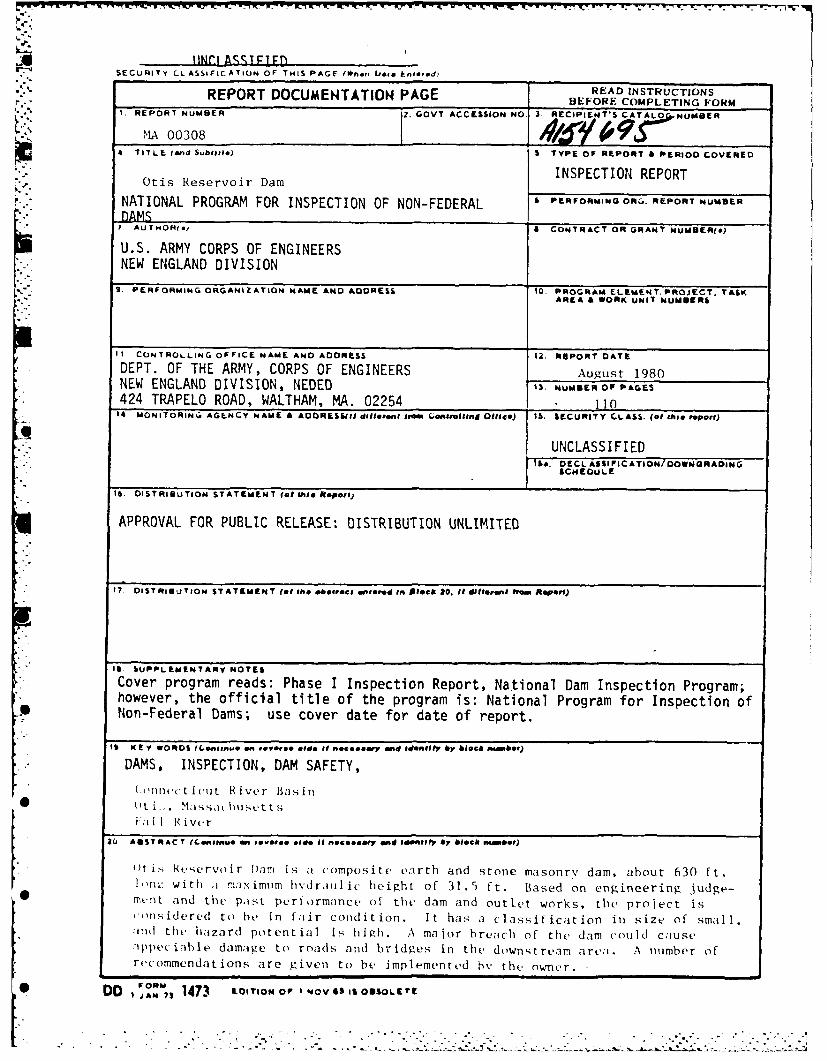
R-14695 NATIONAL PROGRAM FOR INSPECTION OF NON-FEDERAL DAMS 1/2.ADAi4 OTIS RESERVOIR DARM MA. () CO RPS OF ENGINEERS WALTHAM
UNCLASSIFIED F/G i3/i3 NL
8mmm31mmhhhhh
iEEE/l/I/l/QE/EI//////II//I
////////EIIEEEE
IF &P
_ o=.IIINf" -l 1 2 5 M l 1 4 11111 21 6
NATIONAL BUREAU OF"' STANDARDSICGROPY RESOLUTION TEST CHART
II
6
F3.5
|- °8
11111..2. -- ,4.1- -.1- -6
NAINLIUA .STNAD

rI CONNECTICUT RIVER BASIN
OTIS, MASSACHUSETTS
co
12 OTIS RESERVOIR DAMMA 00308 -
II
PHASE I INSPECTION REPORT .
NATIONAL DAM INSPECTION PROGRAM
0- JUNi1 0 1985
G AG
_DEPARTMENT OF THE ARMY
IEW ENGLAND DIVISION, CORPS OF ENGINEERS-
WALTHAM, MASS. 02154.
j AUGUST, 1080
F:85 5 20 089--
w w lw w w -w w w w w w W V V V V S
'K W1 W_ E - Wj_ KZ- w_7 __ .r T -W' K K7 W-, 7-C 1 'r -: w:7 'K: -7 -7 .I~ .* . . . -. - -
6.1
A INr1 ASS I T F 1*- SECURITy CL ASSIFICATION OF THIS PAGE f*h.n Liss. E.ne0ed)
'" REPORT DOCUMENTATION PAGE READ INSTRUCTIONSBEFORE COMPLETING FORM
. REPORT NUMBER 2. GOVT ACCESSION NO. 3 RECIPIENT'S CATAL O0, NUMBER
IMA 003084 TITLE (and S..blltl) S TYPE Of REPORT 6 PERIOD COVERED
i.] INSPECTION REPORTOtis Reservoir Dam
NATIONAL PROGRAM FOR INSPECTION OF NON-FEDERAL 6 PERFORMINGOR. REPORT NUMBERDAMS
7. AUTHOR(.) A CONTRACT OR GRANT NUMBER(.)
U.S. ARMY CORPS OF ENGINEERSNEW ENGLAND DIVISION
9 PERFORMING ORGANIZATION NAME AND ADDRESS 10. PROGRAM ELEMENT. PROJECT, TASKAREIA 4 WORK UNIT NUMBERS
I CONTROLLING OFFICE NAME AND ADDRESS 12. REPORT DATE
DEPT. OF THE ARMY, CORPS OF ENGINEERS August 1980NEW ENGLAND DIVISION, NEDED IS. NUMBER Of PAGES424 TRAPELO ROAD, WALTHAM, MA. 02254 11014. MONITORINC. AGENCY NAME 4 ADDRESS($$ dillteent #roo Go.enhiltnd O1tcel) IS. SECURITY CLASS. (of this report)
UNCLASSI FIEDIto. DECLASSIFICATION/DOWNGRADING
CHEOULE
16 DISTRIBUTION STATEMENT (at this Regpo-i)
APPROVAL FOR PUBLIC RELEASE: DISTRIBUTION UNLIMITED
*T17. DISTRIBUTION STATEMENT (of Ih "steet, enle d In Pletk 20. II different fm A OPOU)
,. It sUPPLEMENTARY NOTES
* Cover program reads: Phase I Inspection Report, National Dam Inspection Program;however, the official title of the program is: National Program for Inspection of
*I Non-Federal Dams; use cover date for date of report.
I9 K E! Y WORDS (L.,netnue en feiVe,. .gsie #g noeeaeeny end 0440011V 6V 6lOck OHM4ib1r)
DAMS, INSPECTION, DAM SAFETY,
(nin-c t icut River Basin* ~~(ItLLM' a~~se
fIII River
8O ASST RACY (Centinwe an e -sel e old* II nst:...aey ad 1400 1fy by block0 ihm OH t)
)t i'; Rtservoir 1)am is . composite earth and stone masonry dam, about 630 ft.l~w; with ,i maximuim hyfdrllic height of 31.5 ft. Based on engineering judge-m.-nt and the past performance of the dam and outlet works, the project isconsidered to he in fair condition. It has a classification in size of small.lad the hazard potential is high. A major breachi of the dam couid causeIppeciable damage to roads and bridges in the downstream area. A number ofrecommendations are given to be implemented by the nW11er.
P-* DDI 43 LTION 001 1NOV 63 IS GOSOLIE't
* o :% 7 ,o..o.o, -o . o , S
- - - - - - - - . 5.- . .- * . - , . - .. . - • .. •S . . .-

_ •. -~-o .-- I-S W
OTIS RESERVOIR DAM
MA 00308 .
I
CONNECTICUT RIVER BASINOTIS, MASSACHUSETTS Accession For
NTIS GRA&I -
p DTIC TAB EUnannounced I]Justification--
* 1 IDistribution/
Availability Codes
Avail and/or
Dist Special
PHASE I INSPECTION REPORTNATIONAL DAM INSPECTION PROGRAM
--..- h
w w w w w w w w w w
* , * • ° ° .° - - 2
; " ? . *.' . -" - .. - ..* - - N - ."' ' -"
-

NATIONAL DAM INSPECTION PROGRAMPHASE I INSPECTION REPORT
Identification No.: MA 00308Name of Dam: OTIS RESERVOIR DAMTown: OTISCounty and State: BERKSHIRE, MASSACHUSETTSStream: FALL RIVERDate of Inspection: 11 JUNE 1980
BRIEF ASSESSMENT
Otis Reservoir Dam is a composite earth and stone masonry dam, approxi-mately 630 feet long with a maximum hydraulic height of 31.5 feet. TollandRoad passes over the top of the dam in a northeast-southwest direction. Thetop width of the dam is about 30 feet, with the stone masonry face batteredat 2H:12V. The upstream face is riprapped with a slope of approximately3H:IV. A stone masonry spillway with a 1 foot high flashboard is locatednear the southwest end of the dam. The spillway has a weir length of approxi-mately 38 feet Oivided in half by a stone masonry and concrete pier whichsupports a steel stringer bridge above. Two 30-inch by 30-inch stone con-duits through the dam serve as a low level outlet for the reservoir. Two
|I -sluice gates at the upstream end of these stone conduits are used as regu- plating gates to control the water level of the reservoir and to partiallydraw the reservoir down during the winter. Thj crest of the dam was graded sothat the dam may serve as an emergency spillway during high flows. Dischargesfrom the spillway and Inw level outlets are into the Fall River and then intothe West Rranch of the Farmington River.
Based on engineering judgement and the past performance of the dam andoutlet works, the project is considered to be in fair condition at the presenttime. The project, however, does have a number of deficiencies which, if notremedied, have the potential for developing into serious conditions.
Because the dam is classified as intermediate size and high hazard po-tential, the test flood is the Probable Maximum Flood (PMF). The test floodinflow for Otis Reservoir, having a drainage area of 16.0 square miles, was Sestimated to be 17,600 cfs. In estimating the test flood,consideration wasgiven to the peak reducing effects of the large swamp areas in the northerlyhalf of the watershed. Reservoir storage would reduce the test flood inflowto a router test flood outflow of approximately 11,900 cfs which would overtopthe dam by about 4.6 feet. The combined capacity of the spillway (withoutflashboards), and the two 30-inch conduits with water at the top of dam is 1100cfs which is 9 percent of the routed test flood outflow.
The 2 PMF was also analyzed and it was estimated that the dam would beovertopped by approximately 2.3 feet for the I PMF routed outflow of approxi-mately 4200 cfs.
0 W W W -

A major breach of the dam could cause appreciable damage to roads andbridges in the downstream area. Loss of more than a few lives would also belikely.
A number of recommendations and remedial measures are given in Sec-tions 7.2 and 7.3 for implementation by the owner. These recommendationsshould be implemented within 12 months of receipt of the Phase I InsoectionReport except as noted.
These recommendations, in general, are as follows:
- Engage a qualified Registered Professional Engineer to performa detailed hydrologic and hydraulic analysis to determine theneed for and methods to increase project discharge capacity.
- Engage a qualified Registered Professional Engineer to design .:repairs for the foundation and supporting structure of thegate house and service bridge, and to design a drainage systemfor the area at the downstream toe of the dam. Since the damis expected to act as a spillway during high flows, the down-stream toe should be protected against erosion caused by theoverflow. In addition, repairs of the two regulating gatesand stem guides should be designed and carried out. TheEngineer should investigate the impact of flashboards onthe stability of the masonry weir and masonry pier at thespi 1 lway.
Leakage noted through the tops of the stone conduits for theV low level outlets should be investigated and monitored. This
should be done immediately upon receipt of this report.
- Reoair or reconstruct the collapsed retaining wall on thenorth side of the discharge channel for the low level outlets.
Brush and grass should continue to be routinely removed from the joints| in the stone masonry and the 7 ea along the base of the dam.
The owner should also implement the recommended remedial program in-cluding the establishment of a formal operation and maintenance program, anda formal surveillance and downstream warning (emergency preparedness) program.A qualified Registered Professional Engineer should also be engaged to make acuin-rehensive technical inspection of the dam once a year.
c 2. . . .% .
John F. CyszProject ManagerMA P.E. No. 28841 .
0~~~ ~ W W
a ..-.

PREFACE
This report is prepared under guidance contained in the Recommendedg Guidelines for Safety Inspection of Dams, for Phase I Investigations.Copies of these guidelines may be obtained from the Office of Chief ofEngineers, Washington, D.C. 20314. The purpose of the Phase I Investigationis to identify expeditiously those dams which may pose hazards to humanlife or property. The assessment of the general condition of the dam isbased upon available data and visual inspections. Detailed investigation,and analyses involving topographic mapping, subsurface investigations, test-
-m ing, and detailed computational evaluations are beyond the scope of aPhase I Investigation; however, the investigation is intended to identifyany need for such studies.
In reviewing this report, it should be realized that the reportedcondition of the dam is based on observations of field conditions at thetime of inspection along with data available to the inspection team. Incases where the reservoir was lowered or drained prior to inspection, suchaction, while improving the stability and safety of the dam, removes thenormal load on the structure and may obscure certain conditions which mightotherwise be detectable if inspected under the normal operating environment -
of the structure.
It is important to note that the condition of a dam depends onnumerous and constantly changing internal and eternal conditions, and isevolutionary in nature. It would be incorrect to assume that the presentcondition of the dam will continue to represent the condition of the damat some point in the future. Only through continued care and inspectioncan there be any chance that unsafe conditions be detected. "
Phasr I inspections are not intended to provide detailed hydrologic •and hydraulic analyses. In accordance with the established Guidelines, theSpillway Test Flood is based on the estimated "Probable Maximum Flood" fort-e region (greatest reasonably possible storm runoff), or fractions thereof.Lecause of the magnitude and rarity of such a storm event, a finding that asoillway will not pass the test flood should not be interpreted as necessarilyposlng a highly inadequate condition. The test flood provides a measure ofrelative spillway capacity and serves as an aid in determining the need formore detailed hydrologic and hydraulic studies, considering the size of thedam, its general condition and the downstream damage potential.
Phase I Investigjation does not include an assessment of the need forfences, gates, no-trespas-ing signs, repairs to existing fences and rail-ings and other iter'is wnich ,'aj be needed to minimize trespass and providegreater security for tKe facility and safety to the public. An evaluationof the project for compliance with OSHA rules and regulations is alsoexcluded.
- -,°', .-.I j- . .
w w w U U U U- U V- U U

TABLE OF CONTENTS
Section Page
Letter of Transmittal
Brief Assessment• .
Review 3oard Page i i-
Preface i
Table of Contents ii-iv
Overview Photo v
Location Map vi
REPORT
1. PROJECT INFORMATION
Li 1.1 General I-0
a. Authority I-ib. Purpose of Inspection I-I
1.2 Description of Project I-,
• a. Location 1-I
b. Description of Dam and Appurtenances I2c. Size Classification 1-2
d. Hazard Classification 1-2
e. Ownership and Operator 1-2
f. Purpose of Dam 1-2
?1 g. Design and Construction History 1-3
h. Normal Operational Procedure 1-3
1.3 Pertinent Data 1-4
a. rainage Area 1-4
b. Discharge at Damsite 1-4 - .
c. Eli?vati on 1-5d. Reservoir 1-5
e. 3t-rage 1-6
f. Reservoir Surface 1-6
g. Dam 1-6 ..-
h. Diiersion and Regulating Tunnel 1-6i. Spillway 1-5j. Regulating Outlets 1-7
"" ii
.... ..

Section Page
2. ENGINEERING DATA
2.1 Design Data 2-1
2.2 Construction Data 2-1
2.3 Operation Data 2-1
2.4 Evaluation of Data 2-2 -
a. Availability 2-2b. Adequacy 2-2c. Validity 2-2
3. VISUAL INSPECTION
3.1 Findings 3-1
a. General 3-1b. Dam 3-1c. Appurtenant Structures 3-3d. Reservoir Area 3-4e. Downstream Channel 3-4 •
3.2 Evaluation 3-4
4. OPERATIONAL AND MAINTENANCE PROCEDURES
4.1 Operational Procedures 4-1
a. General 4-1b. Description of any Warning System in Effect 4-1
4.2 Maintenance Procedures 4-1
a. General 4-1 -b. Maintenance and Operating Facilities 4-1
4.3 Evaluation 4-1
5. EVALUATION OF HYDRAULIC/HYDROLOGIC FEATURES
5.1 General 5-1
5.2 Design Cata 5-1
5.3 Experience Data 5-1
5.4 Test Flood Analysis 5-2
5.5 Dam Failure Analysis 5-2
iii
. .. - " .

Section Page
6. EVALUATION OF STRUCTURAL STABILITY
6.1 Visual Observations 6-1 .0
6.2 Design and Construction Data 6-1
6.3 Post-Construction Changes 6-1
6.4 Seismic Stability 6-1
7. ASSESSMENT, RECOMMENDATIONS AND REMEDIAL MEASURES
7.1 Dam Assessment 7-1
a. Condition 7-1 -
b. Adequacy of Information 7-1c. Urgency 7-1
7.2 Recommendations 7-1
7.3 Remedial Measures 7-2
a. Operating and Maintenance Procedures 7-2
7.4 Alternatives 7-2
APPENDI( ES
AP P, X A - INSPECTION CHECKLIST
APPENCIX B - ENGINEERING DATA
APPENDIX C - PHOTOGRAPHS
I APPENDIX D - HYDROLOGIC AND HYDRAULIC COMPUTATIONS
APPENDIX E - INFORMATION AS CONTAINED IN THE NATIONALINVENTORY OF DAMS
iv
0
9 .
S S S S S S S S S S SSS.U U

I4
OVRIWO
OTIS ESERVIR DA

(Photo 14) 6,y~
-,~Drainage AJ-a
SEE APPENDIX D-C' 'A FOR CONT)NtUATSON
D ONSTEM ZADAE
ROUTE S SIDGE ROOtE LE
IMS~T $ Idnt~l~tlo No MAB0a0

NATIONAL DAM INSPECTION PROGRAMPHASE I INSPECTION REPORT
OTIS RESERVOIR DAMSECTION I - PROJECT INFORMATION
1. I GENERAL
a. AuthorityPublic Law 92-367, August U, 1972 authorized the Secretary of the
'rmy, through the Corps of Engineers, to initiate a National Program of Daminspection throughout the United States. The New England Division of the Corpsof Engineers has been assigned the responsibility of supervising the inspec-tion of dams within the New England Region. Robert G. Brown & Associates, Inc.nas been retained by the New Lngland Division to inspect and report on selecteddaTs in the Commonwealth of Massachusetts. Authorization and notice to proceed..,ere issued to Robert G. Brown & Associates, Inc. under a letter of 14 Marchg, !R fro:T 'illijtm E. Hodgson, Colonel, Corps of Engineers. Contract No.
5AC,.33-R)-C- Y!37 has been assigned by the Corps of Engineers for this work.
Pur ose of Inspection(i) To perform technical inspection and evaluation of non-Federal
darns to identify conditions which threaten the public safetyand thus permit correction in a timely manner by non-Federalinterests. _
() To encourage and prepare the States to initiate quickly,effective dam safety programs for non-Federal dams.
3) To update, verify and complete the National Inventory of dams.
' c SLRIPTION OF PROJECT S
i. Location
,tis Reservoir Dam is located in the Town of Otis, Massachusetts., : on the Fall River approximately 0.91 miles upstream from the river's
,' .vnc ,rth the viest branch of the Farmington River. The dam impounds Otis"jvuir which is one of the largest recreational water bodies in Westernchett . Otis Re,ervoir Dam is shown on the USGS Tolland Center, Mass. -
(_1 uadranjl.,_ i.t Ltitude 42 09.6' and Longitude 730 03.5'. Access to the dam-,i to i by ,ll ,n' Road which passes over the dam.
n . o , i-n jf DaTI andAppurtenancesR er,: a. in is a composite earth and stone masonry dam, approxi-
S i, f 1)t ,; ..b:r I ,,,<j;uni hydraulic height of 31.5 feet.
Th, toij n a vidtn of about 30 feet and carries Tollandhi .n u h t Lijr ii n - (,(1W crete ,aved width of 20 feet. The downstream
. ., -, , 1 , /I ' I otres, joints, having a batter of 2H:12V. The1t1-ly : a and is orotected by dumped stone riprap.
...' :, . ,i, C.) According to vailable drawings and
-1
'• ' • "" n" " - ; " " " i uinahlna i mnnuuh n f nnnunu u~ud inn

SECTION 4OPLRATIOi'fAL AND MAINTENANCE PROCEDURES
I I 4'A L PROCEDURES
u rai niorocedure-, for the darn are not formally established-i-n thLe ex erience of the operating personnel.
i._-otion- of any_ Warni nq Sstem i n EffectT I-re is rio foriial warning system in effect. During the summer the
ie vn Fr a 'sver al times a day by the Divi sion of Forest and Parks personnel11l-,rc n tdte Forest.
4. 1 IT NANCE PROCEDURPES
Th ,re is no formal Maintenance manual for thin project. Mainten-is rn i it --i needed.
U -iing FacilitiesD',s5ri cut from the top of the darn and downstream toe area about
T. e 5 IJsoir (nnine is started once a week, and the engine and~tijtre two gates receive periodic maintenance. An
41I,(tinl of tnrc qates and stone conduits was conducted in Aprilir Aoioeniix B) . The underwater inspection team removed de-
Are ff thre late openings.
fr tot: iai onalI and ma intenance pl an , i ncl udi ng an annualii1 nseti on by -i qualIi f ied Regi stered Profess ional
ii 1~. * rito insure that probl ems which are encountered ran be1 j I eli pet-rd of time. A formal written surveillance
:.' .. le r) eg -ency preparo!dness) plan should be establ ished for
IW*

The major deficiencies noted during the investigation are, in general:
- movement of the gate house which is causingthe stem guides for the two 30-inch by 30-inch gates to bind.
- leakage through the roofs of the two 30-inchby 30-inch stone conduits.
- seepage at L.,e downstream face and toe of thedam. .0
- need for protection against erosion of thecrest 3nd downstream toe of the dam duringemergency overflow.
- partially collapsed stone retaining wall forthe low-level outlet discharge channel. S
- rusting of steel bridge over the spillway.
-5
• g g • • • • • • • g 0

Luout 120 feet downstream of the stone conduit outlets, there is a concreteArtucture with steel racks and a steel grate footbridge. The top of the - .steel racKs are about 3 feet higher than the outlet inverts of the stoneconduits. According to the Division of Forest and Parks personnel thisconcrete structure was constructed by the Farmington River Water Power Com- pany for the purpose of trapping fish carried out of the reservoir when thelow level outlets were open. The fish screens are now missing and the foot-bridge has been vandalized. This structure can be seen in Appendix C, Photo-graph 11.
d. Reservoir Area .•The 15-mile shcreline of Otis Reservoir is largely developed with
summer cottages, and private and public recreation areas. The shoreline inthe area of Tolland State Forest is undeveloped except for campsites and apublic boat launching area. Ownership of the reservoir shoreline up to acertain elevation (approximate elevation 1424) is claimed by the Departmentof Environmental Management which acquired the dam and flowage rights from theFarmington River Water Power Company. Data relative to the depth of the S
reservoir is given on Sheet 18 of Appendix D. The reservoir is reported tohave a mean depth of 22 feet and a maximum depth of 48 feet. There are sev-eral small islands within the reservoir with the largest being Clark Island.
e. Downstream ChannelThere are two downstream channels; one from the low-level outlet and
the other from the spillway. S
The channel for the low-level outlet (two 30-inch by 30-inch"tone conduits) is contained by stone retaining walls for a distance of about10 feet downstream of the dam. The northerly retaining wall is partiallycollapsed and requires repairs. About 120 feet downstream of the dam thereis a concrete and steel structure which formerly served as a fish trap. Thisstructure has been vandalized and no longer serves its intended purpose (seeAppendix C, Photograph 11). Approximately 100 feet downstream of the fishfrap structure, the channel falls over an almost vertical drop. (See App-n-!iix C, Photograph 12.) The spillway channel lies on bedrock and has a steepj,a,ient. Trees and brush were noted growing and overhanging the channel.The spillway channel converges with the low-level outlet channel approximatelyJisO feet downstream of the dam.
.? EVALUATION
Visual observations made during the course of the investigation re-r dofi(iencies which at present do not adversely affect the ade-
o tn. . qowevr, these deficiencies do require attention and, )J b cor rer t:d Lnfore further deterioration leads to a hazardous con- .0
( ;',, o':l. ,eature o So improve these conditions are given in Sec-7.
3 4
.S ..
• o .- . - . .
.. -.- w w w " ° ,

The upstream face of the dam above the waterline is covered withdumped riprap. No undercutting of the riprap or roadway was observed.
c. Appurtenant StructuresA wood-framed building (18 feet by 20 feet), housing the operat-
ing mechanisms for the two 30-inch by 30-inch low level outlets, is locatednear the center of the dam (see Appendix C, Photographs 1 through 4). Thegatehouse was constructed about 1901 and is supported on a single concretecenter pier running the width of the building. A steel stringer servicebridge spans from concrete abutment piers at the top of the dam across thecenter pier as shown in Photograph 3. The abutment piers are tipped toward
U the reservoir and are about 2" out of plumb. The center pier is also tippingforward causing the gate stem guides mounted on its face to bind the gate stems.The abutment piers need to be repaired to provide resistance against rotation of :.'. -
the gatehouse about the center pier.
During the inspection the two 30-inch by 30-inch gates were operatedby use of the gasoline engine which was started by a hand crank. The engine 0started without difficulty and the gates were partially opened and then closed.An indicator was noted on the wall of the gatehouse indicating the position ofthe gates. Inspection of the gate stems indicate that stem guides are mountedon the concrete center pier which supports the gatehouse. Since the center pierhrs tipped toward the reservoir, the stem guides are now causing the gate stemsto bind. It appears that the stem guides have been modified in the past to com-pensate for the tipping of gatehouse pier; however, additional movements of theier (I to 2 inches) have occurred subsequently. During closing of the gates,
one gatehouse lifted off the center pier. The 36-inch by 36-inch gates were ob-2rved from the conduit outlets at the downstream face of the dam. Both gatese>' leaking along their perimeters, with most of the leakage being at the tops. t'e gates. The gate leakage was estimated at about 1 cfs. (An underwater,,e(ction report describing the gates and trash rack at the head of the stone,n iit is included in Appendix B.)
Lrakae through the roofs of the two stone conduits was noted at a• e from the downstream face of the dam. According to record plansIli of leakage corresponds to where the 1888 work jointed against the
- ,I a] i5 .tructure. This leakage condition requires further investigation* in.t.' if it is related to the shallow depression above in the pavement
i. i, Road. Repairs will be necessary if the leakage is causing internalin the dam. The horizontal and vertical alignment of the two stone
. iood.
,, j the downstream face of the dam, the discharge channel for.. is contained between two stone retaining walls. The
" , n~-qe channel between the two retaining walls is 16 feet. -, ,itir, wall is partially collapsed. (See Appendix C, Photo-
I " i, i'ng wall should be repaired since further collapsei -1 :,ckaoe of the discharge channel. Other obstructions such
i, , uverhanging trees should be removed from the channel.
3-3
............... .-.....--...- ... .....i'...T-....T" . . i i-

lju teet to the northest. Some of the seepage is the result of water passinghroigh the joints in The cut stone masonry (see Appendix C, Photograph 9).'is downstream seepage condition should be monitored and investigated further.
Consideration should also be given to the feasibility of a drainage system toallow seepage to be collected and monitored.
There is no riprap or other means of erosion control at the down-stream toe of the dam which would protect the base of the dam during periods .when emergency spillway flow might occur. It is not known if the entire lengthof the stone masonry at the downstream face rests on ledge. In any event theearth banked against the downstream stone masonry face adds additional resis-tance to sliding and forward movement of the stone masonry, and should there-fore be protected against erosion which could be caused by emergency overflow.
- Pavement on the top of the dam extends only for the width of Tolland "Road. Pavement should be constructed to cover the entire width of the dam for
- at least 300 feet (within the emergency spillway section). The pavement shouldbe designed to prevent flow of water under the pavement during emergency over-f Iow.
The principal spillway (see Appendix C, Photograph 8), is a stonemasonry overflow which is founded on bedrock. The stone masonry crest is approxi- Smately 6 feet high at its northeast end, and approximately 4 feet high at itssouthwest end. The spillway has a total length of 38 feet and is divided in e-qual lengths by a 2 foot wide stone masonry and concrete pier as can be seen inPhotograph 8.
The endwalls of the spillway serve as abutments to a steel strinqer 0bridge (Tolland Road). The bottom of the steel stringers are 7.3 feet abovethe crest of the stone masonry spillway. There are 10 stringers, 12 inchesdeep, 2.5 feet on center, which are covered with steel bridge decking and bi-tuminous concrete pavement. Concrete surrounds the ends of the stringers atboth abutments. The stringers appear continuous over the center pier. Thestringers and steel decking are rusted and should be scraped and painted.
Water approaches the spillway crest through the bridge opening.The floor of the bridge opening (approach channel) is comprised of gravel andcobbles with no obstructions noted. The stone masonry spillway has a single11" thick plank flashboard about 1 foot high. The ends of the flashboard areancnored in slots (32 inches high) as can be noted in Photograph 8. One inchdiameter steel pipes about 2J feet apart along the stone masonry spillway crest
3 provide intermediate support for the flashboard. No notches were visible in thesteel pipe flashboard pins, which would insure that the pins would yield.The upstream face of the spillway and flashboard were covered with a plas-tic membrane, presumably for leakage control. There is evidence that thestone masonry spillway has been repaired as noted by an area of formed con-crete at the face of the spillway near its northeast end.
Steel beaimi iqu3td rails with steel posts are located at each side ofIolland Road including across the spillway bridge.
3- 2
. . ..-.

SECTION 3VISUAL INSPECTION --
3.1 FINDINGS
a. GeneralOtis Reservoir Dam was inspected on June 11, 1980. The weather was . "
clear and sunny. The water level of the reservoir was at elevation approxi-mately 1419.7 or about 2 inches below the flashboard crest. The entire down-stream face and toe of the dam and spillway were visible during the inspection.The upstream face could only be viewed above the noted water level.(Appendix C, -Photograph 2 shows the upstream face of the dam, gate house and gates, whilethe reservoir was drawn down in 1956.) During the inspection, the gasolineengine was started and the gates were operated by the Department of Forest andParks personnel. The two 30-inch by 30-inch gates were observed from the out-lets of the stone conduits at the downstream face of the dam. -
b. DamThe earth embankment section and cut stone masonry at the downstream
face of the dam appear in generally fair condition. The horizontal and verticalalignment of the stone masonry face is good and all of the stone blocks appearstable (see Appendix C, Photograph 6). Small brush and grass was noted growingthrough the joints in the stone masonry on the downstream face. This should beremoved as part of the routine maintenance. •
The pavement for Tolland Road, which passes over the dam,is in goodcondition. During inspection of the two 30-inch by 30-inch stone conduits, itwas noted that concentrated leakage is occurring through the tops of the con-duits at a location approximately 20 feet from the downstream face of the dam.The area of this leakage corresponds roughly to a slight depression in the pave-
I ,.;nts, as evidenced by the puddles of surface water in Appendix C, Photographs 01 and 3. This condition requires further investigation to determine if thereis any relationship between the leakage through the roofs of the conduits andthe depression in the roadway.
According to available plans and correspondence on file with theBerkshire County Commissioners, the top of the dam was designed in 1888 to acta an emergency spillway during high flows. A survey of the dam crest made in1956 indicated that the road had been raised during subsequent years due tofil being added to the bed of Tolland Road which passes over the dam. A plandated June 1956 by W. A. Heaphy was the basis of the regrading work done afterthe 1955 flood to restore the top of dam elevation to the 1888 design grades._ -irements .::adr during the Phase I Inspection indicate that the present top)f cam elevations correlate reasonably well with the elevations shown on the'956 plan. Repaving has probably added about 0.2 feet to the crest elevation. -
The downstream toe of the dam is an earth embankment against the cut . -
,tono masonry. Four seepage areas were noted at the downstream base of the] bot, en 'h( low level outlet discharge channel, and a point approximately
3 1
p w - w •- w S

Mr. Pearl Rote, the previous dam caretaker employed by the FarmingtonRiver Water Power Company presently lives in a state-owned building near the
damsite but is not an employee of the Commonwealth and has no responsibility
for the dam operation. Mr. Rote and his father were the caretakers of the
dam for the Farmington River Water Power Company since before 1900.
2.4 EVALUATION OF DATA
a. AvailabilityExisting information was made available by the Massachusetts Depart-
ment of Environmental Management; Massachusetts Department of Public Works,
=" District 1; Division of Forest and Parks; and the Berkshire County Commissioners .
(William Heaphy, County Engineer).
b.. -_.quacyThe final assessments and recommendations of this investigation are
based primarily on the visual inspection, hydraulic and hydrologic calculations,
past performance history, and sound engineering judgment.
c. ValidityIn general, the information obtained from available plans, specifi-
cations, correspondence and reports is consistent with observations made dur-
,nq the inspection and is therefore considered reliable.
2 2
W •
w w w w W U

SECTION 2ENGINEERING DATA
2.1 DESIGN DATA 0
Plans dated 1887-88 show the original dam as constructed in 1866, and plansand specifications for modifications to the dam made in 1888, are on file with theBerkshire County Commissioners, Office of the County Engineer, Pittsfield, Massa-chusetts. The reservoir flowed over wetlands and three natural water bodies.
-2.2 CONSTRUCTION DATA
Correspondence and reports of engineers covering the work done on the damin 1888 are on file with the Berkshire County Commissioners. Plans dated 1956for regrading of the top of dam are also on file with the Berkshire CountyCommissioners.
2.3 OPERATION DATA
The two 30-inch by 30-inch gates are operated as necessary to maintaina summer water level of approximately 1420 MSL. During the fall the gates areopened and the reservoir is drawn down approximately 8 feet to elevation 1412MSL. Winter drawdown is done for the purpose of protecting docks from icedamage. The gates are raised and lowered simultaneously and automatically, 0using a gasoline engine which is equipped with a gear box. The engine isstarted with a hand crank. The gasoline engine is reportedly started at leastonce every week. The gates can also be operated manually with a hand wheel.At present the gates are not opened more than 25 inches because of the owner'sconcern that the gates might fall out of their slides. An indicator on thewall of the gate house shows the position of the gate. Because of the presentstructural condition of the gate house, closing of the gates too tightly will .0cause the gate house to lift off its pier.
In April of 1980, Massachusetts Department of Environmental Management(MP7M) requested an underwater inspection of the low level outlets and regu-lating gates. The underwater inspection was performed by the MassachusettsDepartment of Public Works (MDPW), Underwater Bridge Inspection Team. The
EJ divers' report is included in Appendix B.
The water level in the reservoir is observed on a gage board located onthe northeast end of the concrete pier which supports the gate house. Ele-vation 25' - 4" on the gage corresponds to elevation 1419.9 which is the crest.f the first flashboard on the spillway.
ADNo stream gage or other flow measurement apparatus was observed at the
s.e. However, the USGS maintains a stream gage downstream of the damsite . ..3.4 :Ies below the confluence of the Larkum Pond outlet. Brush is removedinnuaoly from the area near the downstream toe of the dam by MDEM personnel.
* ~1DEM personnel from the Tolland State Forest are used for maintenance and day- .. ' . -
-. to--a'y oDeration and surveillance.
2 1
w. w - WW

(2) Length of weir - 38 feet (total length divided in half by pier).
(3) Crest elevation - 1418.9 MSL without flashboards. 1419.9 MSLwith present 12" high flashboard (stone slots available for 32"of flashboard height). Note: USGS shows water surface at el.1421 MSL which is within about 1 foot of elevation given onplan dated 1956, on file with Berkshire County Commissioners.
(4) Gates - nonE on spillway.
(5) U/S Channel - Otis Reservoi.. Spillway is beneath bridge
-" which carries Tolland Road over dam.
(6) D/S Channel natural channel in bedrock; steep slope.
Regulating Outlets( ) Invert - 1391 (outlets).
(2) Size - 2 low level outlets 30" by 30", combined capacity of --360 cfs @ 1427.1 MSL.
(3) Description - Outlets are stone conduits through the dam.(See Appendix C, Photograph 5.) Conduit length is approximately63 feet divided by stone block septum.
(4) Control mechanism - Two gate operators mounted on flood stands.Gates can be operated by a gasoline engine which is equippedwith a gear box, or they can be opened by hand wheels. An in-dicator on the wall of gate house shows the position of gates.An automatic control shuts off the gasoline engine when gatesreach a certain height. The gates bear the marking: CoffinValve Co., Boston, Massachusetts, date August 8, 1923.
(5) Other - Inlets of low level outlets have wooden trash rack.(See Appendix C, Photograph 2, taken in 1956.)
1 7
w w --- - w ---

e. Storage (acre-feet)I Normal pool - 22,000 with flashboard
. (2) Flood control pool - not applicable.
(3) Spillway crest pool - 22,000.
. (4) Top of dam - 24,600.
(5) Test flood pool - 29,900.
- f. Reservoir Surface (acres) -"(I) Normal pool - 1,000.
(2) Flood control pool not applicable.
(3) Spillway crest pool - 1,000.
(4) Top of dam - 1,050.
(5) Test flood pool 1,180.
g. Dam (no dike)M Type - composite earth and stone masonry/gravity.
(2) Length - 630 feet.
(3) Height - 31.5 feet.
(4) Top width - 30 feet.
(5) Side slopes - 2H: 12V, downstream masonry; 3H:lV, upstream embankment.
(6) Zoning - cut stone masonry with mortar joints on front face;earth fill behind stone masonry.
(7) Impervious core - type of earth fill, unknown.
P (8) Cutoff- unknown. -
(9) Grout curtain - unknown. . -.
(10) Other - steel stringer bridge over spillway.
h. Diversion and Regulating Tunnel - not applicable (see j.)
i. Spillway(1) Type - cut stone masonry vith mortar joints. Spillway weir has
12" hiqh flashboard above masonry crest.
1 -6
-ip. i
* U U U U w w w'.w w

. . . . . . . . . . . . . . . .. r -,. ,,o . ..
60
(7) Total spillway capacity at test flood elevation o2600 cfs@ 1427.1 MSL (without flashboards - not including flow overtop of dam).
(8) Total project discharge at top of dam - 1100 cfs @ 1422.5 MSL.(Includes discharge of 2 regulating gates plus ungated spill- .way without flashboards.)
(9) Total project discharge at PMF test flood elevation - 11,900cfs @ 1427.1 MSL (without flashboards).
(10) Total project discharge at 2 PMF elevation - 4200 cfs @ 1424.8MSL (without flashboards).
c. Elevation (Datum is feet above mean sea level NGVD referred to in text
as MSL)(1) Streambed at toe of dam - 1391.
(2) Bottom of cutoff - unknown.
(3) Maximum tailwater - unknown.
(4) Normal pool - 1420 according to plan available with Berkshire
County Commissioners; 1421 by USGS Quadrangle.
(5) Full flood control pool - not applicable.
(6) Spillway crest - 1418.9 without flashboard1419.9 with flashboard.
(7) Design surcharge (Original Design) - about 1423.
(8) Top of dam - 1422.5 (low point).
(9) PMF test flood surcharge - 1427.1.
(10) PMF surcharge - 1424.8.
d. Reservoir (length in feet)(1) Normal pool - 18,000. -
(2) Flood control pool - not applicable.
(3) Spillway crest pool - 18,000.
(4) Top of dam - 18,400. .-4
(5) Test flood pool - 19,200.
1-5
fS
00 0 0 0
-.-."'----..F;; .: ':,...,..' - .' -' ,' : ' , ',_ - .% t " 4 -- 4 4 ,, . .-. , '- -. , m - , - ' -, - , '
-- . "

1.3 PERTINENT DATA
a. Drainage AreaThe total drainage area contributing to Otis Reservoir is 16.0
S'square miles. The drainage area is oriented with its long axis in a north-south direction; and is northerly limit extends to the area of the Massa-chusetts Turnpike in the Town of Becket. The watershed has a length ofapproximately 8 miles and an average width of approximately 2 miles. Thebasin is covered by forests and wetlands, and a large percentage of openwater. Open water wetlands comprise about 50% of the watershed. The re-mainder of the watershed is rolling, wooded, terrain. Elevations in thewatershed range from 1420 MSL at Otis Reservoir to 1799 MSL at the northerlyfringe.
. The northern half of the drainage area lies above Route 23 anddrains through Big Pond. Big Pond is a shallow body of water having a sur-face area of about 330 acres, and a normal water surface elevation of 1472.The surface level of Big Pond is controlled by a 2 foot high, 90 foot longconcrete weir structure shown in Appendix C, Photograph 13.
The southern half of the watershed (south of Route 23) consists ofuncontrolled areas draining directly into Otis Reservoir.
S'b. Discharge at DamsiteDischarges at the damsite are over the 38 foot long stone masonry
spillway which has one wooden flashboard at its crest, and through two 30-inchby 30-inch low level outlets. According to a 1956 plan on file with the Berk-shire County Commissioners, the crest of the stone masonry spillway is at ele-vation 1418.9. The top of the wood plank flashboard is about elevation 1419.9.When the water level reaches approximately elevation 1422.5, water begins toflow over Tolland Road which has been graded to provide a 260 foot long emer-gency spillway.
(1) Outlet works - two 30-inch by 30-inch low level outlets atelevation 1391; combined discharge capacity 330 cfs @ 1422.5MSL.
(2) Maximum flood at damsite - unknown. Water either overtoppedthe dam or was very near to the top of dam in 1955. The damwas lowered by about 1.5 feet after the 1955 flood.
(3) Ungated spillway capacity at top of dam - 450 cfs @ 1422.5MSL, with flashboards; 780 cfs without flashboard.
(4) Ungated spillway capacity at test flood elevation - 2600 cfs@ 1427.1 MSL (without flashboards- not including flow overtop of dam.)
(5) Gated Spillway capacity at normal pool elevation - not applic-able.
(6) Gated spillway capacity at test flood elevation - not applic-
able.
1 4
- - ° : :,* . ..... ...... .. ]T. . .-.... - , . -.
'~~~ ~ W W .-.-- " V - V "" 'W:; ! :::::"-:::T :. :::::::::.-:--;:-': -::""),. -: .. .:. .> : . .:. ..- :.: ;. .. :. ..... .

0
" by the Commonwealth of Massachusetts in 1967. The dam impounds Otis Reservoir-" which is now used for recreation. Tolland State Forest is located approxi- :-., ...
mately 1 mile south of the damsite.
3 g. Design and r'struction HistoryAccording to records on file with the Berkshire County Commissioners,
the dam was originally built in 1866 by the Farmington River Water Power Company(FRWPC). The dam was modified by the FRWPC in 1888 in order to strengthen thedam. Work completed in 1888 included construction of a grouted stone masonrywall over the downstream face of the original dam, reconstruction of the stonemasonry spillway, and grading of the top of the dam so that emergency spillway ..
- action would occur at higher flows. Designs for the 1888 repairs were prepared -
by William Hill, Engineer for the Farmington River Water Power Company. Plansand Specifications, and subsequent modifications were submitted to and approved . *-- -
by the Commissioners of Berkshire County. The Commissioners retained Engineer-: D.M. Greene to advise on the plans.
Plans, specifications, and various correspondence relative to the1888 work are presently in the files of the Berkshire County Commissioners inPittsfield, Massachusetts.
After Hurricane Diane in 1955, the FRWPC lowered the dam by regrad-ing Tolland Road to remove fill which had been placed over the dam in yearssubsequent to 1888.
A plan for regrading, on file with the Berkshire County Engineerdated June 1956, calls for lowering of the top of dam by approximately 1.5feet for a length of about 275 feet. The top of the dam was set at elevation1422.3 for a length of approximately 260 feet ot act as an emergency spillwaywhich is 3.4 feet above the stone masonry crest of the spillway. Measurementstaken at the site indicate that the work called for on the 1956 plan was done.Repaving work over the last 20 to 25 years has probably raised the grade 0slightly so the low point now is at 1422.5 MSL.
Repairs were also made in 1956 to the stone block dividing wall (septum)between the two 30-inch stone conduits. This repair work included anchoringone of the stones which was dislodged. The stone block was repositioned andanchored with metal straps. (See 1980 MDPW Underwater Inspection Team Report
U in Appendix B.)
h. Normal Operating ProceduresThe two 30-inch gates are utilized to maintain a summer water level
of approximately elevation 1420. A gage board on the pier of the gate houseas a reference mark. Elevation 25' - 4" on the gage is equivalent to
'evation 1419.9 which is the elevation of the top of the first flashboard onhe -oi 1 lway.
During October and November the regulating gates are opened to drawtic reservoir to approximate elevation 1412 so that docks along the reser-iill no. be damaged by ice. The drawdown also allows for flood storage
, nq tho sping runoff period.
1-3
...........................

0 7
other records the dam was originally constructed in 1866. The dam was modi-- fied in 1888 for the purpose of strengthening the original dam according to*" records on file at the Berkshire County Commissioners' office.
A stone masonry spillway with a single flashboard is located nearthe southwest end of the dam. The spillway has a weir length of approximately38 feet divided in half by a stone masonry and concrete pier which supports asteel stringer bridge above. (See drawings in Appendix B-3.)
The top of the dam is graded so that 40 percent of the crest mav act as - -an emergency spillway during high flows. Water may rise approximately 3.6.feet over the stone masonry spillway weir (2.6 feet over flashboard) before
* flowing over the dam.. -
Two 30-inch by 30-inch stone conduits through the dam serve as alow level outlet for the reservoir. According to the records on file with the . -.
- Berkshire County Commissioners, the stone blocks making up the conduits areconnected with steel rods. Two sluice gates at the upstream end of these twostone conduits are used as regulating gates to control the water level of thereservoir and to partially draw the reservoir down during the winter. The two ;gates are normally operated with a Wisconsin gasoline engine with a gear boxand chain drive. The gates may also be raised and lowered manually. The gateoperators, gasoline engine and gear box, are located in an 18 foot by 20 footwood-framed building which is balanced on a single center pier. The gatestems are attached to the upstream side of the center concrete pier and extendup into the floor of the wooden gate house. Photograph 2 in Appendix C showsthe gate house and gates with the reservoir drawn down in 1956. A wooden trash .rack is located upstream of the inlets to the two stone conduits as can be seenin Photograph 2.
c. Size ClassificationIntermediate (hydraulic height 31.5 feet; storage 24,600 Ac. Ft.)
based on storage (1000 to 50,000 Acre Feet) as given in the Recommended Guide-lines for Safety Inspection of Dams.
d. Hazard ClassificationThe dam is in a high hazard category because of major breach of
thQ dam could cause appreciable damage to roads and bridges in the downstreamarea. Loss of more than a few lives would be likely. The village of NewBoston lies on the West Branch of the Farmington River about 5 miles downstreamof the damsite. (See Section 5.5.)
e. Ownership and OperatorThe dam is owned by the Commonwealth of Massachusetts, Department of
-nvironmental Management. The day-to-day operation of the dam is assigned to.n -giona! Forest and Park Supervisor: Mr. Douglas Poland, Pittsfield State .
For-e;t, Cascode Street, Pittsfield, MA 01201, Telephone: (office) 413-442-8992, 9(How?) 413-623-8348.
f. Purpose of Dam . -The dam was formerly owned by the Farmington River Water Power Co. and --- * "..
wa um'd to rejulate flow to downstream mills. The dam and reservoir were purchased
1-2 0
. .W .
* - . .- "--
i . .... . .~ .k .

SECTION 5EVALUATION OF HYDRAULIC/HYDROLOGIC FEATURES "v.-
5.1 GENERAL
The total drainage area contributing to Otis Reservoir is 16.0 squaremiles. The watershed has a length to width ratio of roughly 2 to 1.
Open wate.' and wetlands comprise about 50% of the watershed. The re-mainder of the watershed is rolling wooded terrain. Elevations in the water-shed range from 1420 MSL at Otis Reservoir to 1799 MSL at the northerly fringe.
The northern half of the drainage area lies above Route 23 and drainsthrough Big Pond. Big Pond is a shallow body of water having a surface areaof about 330 acres, and a normal water surface elevation of 1472. The sur-face level of Big Pond is controlled by a 2 foot high, 90 foot long concreteweir structure shown in Appendix C, Photograph 13.
The southern half of the watershed (south of Route 23) consists ofuncontrolled areas draining directly into Otis Reservoir.
5.2 DESIGN DATA
The original dam at Otis Reservoir was constructed in 1866 and waslater modified in 1888. According to flow data on the record plans, thedesign capacity of the spillway was 840 cfs with a head of 4 feet. The de- . .sign discharge capacity of the low-level outlets was 320 cfs at "full pond".Water flowing over the dam at a depth of 1 foot for a length of about 125feet was intended to pass 414 cfs, thus the total design discharge capacityappears to have been 1574 cfs.
5.3 EXPERIENCE DATA
According to the former gate keeper for the Farmington River WaterPower Company and Division of Forest and Parks personnel, Hurricane Diane,in August 1955, caused water to rise near or above the level of the top ofthe dam which was approximately 1.5 feet higher than the present top of dam .
elevation.
Since 1969, the U.S. Geological Survey has maintained stream gageNumber 01185100 0.4 miles downstream of Otis Reservoir on the Fall River belowthe confluence of the Larkum Pond outlet (drainage area, 16.5 square miles).(Note: The location of the stream gage is incorrectly shown at the dam on theUSGS Quadrangle.) The maximum recorded discharge during the period of recordoccurred in 1972 with a flow of 422 cfs.
5 1i-i
*1
U U U U U U V V W V W :'S -

5.4 TEST FLOOD ANALYSIS
Otis Reservoir Dam is classified as intermediate size, having a hy-
draulic height of 31.5 feet and a top of dam storage of 24,600 acre feet.The dam was determined to have a high hazard classification. Using the -Recommended Guidelines for Safety Inspection of Dams, the test flood is theProbable Maximum Flood (PMF).
The Probable Maximum Flood (PMF) was estimated using methods containedin Preliminary Guidance for Estimating Maximum Probable Discharges in Phase IDam Safety Investigations, issued by the New England Division Corps of Engin-eers. (CSM value of 1100 cfs per square mile was selected midway between curvefor flat terrain and rolling terrain.)
The PMF test flood inflow from the square mile drainage area was esti-mated to be 17,600 cfs. Storage effects would reduce the test flood inflow toa routed test flood outflow of approximately 11,900 cfs.
During test flood conditions water would rise to elevation 1427.1 whichis about 4.6 feet above the top of dam. Water would be passing over the spill-way at a depth of 8.2 feet, and would amount to 2,600 cfs. The combined capa-city of the spillway (without flashboards), and the two 30-inch low level outlets,with water at the top of the dam (1422.5 MSL) is 1100 cfs which is 9 percent ofthe routed test flood outflow. The I PMF was also estimated and it was foundthat during this event, water would rise to elevation 1424.8, or about 2.3 feet •above the top of dam. The I PMF routed outflow at the damsite is estimated tobe 4,200 cfs.
In both analyses it is assumed that the two 30-inch gates are open andare discharging freely. It is also assumed that the flashboard pins yield onthe principal spillway. The pool level at the start of the reservoir routing -
was assumed to be 1420 MSL.
Based on available plans the PMF test flood surcharge exceeds the designsurcharge (elevation 1423 approximately), by about 4 feet and the I PMF surchargeexceeds the design surcharge by approximately 2 feet.
5.5 DAM FAILURE ANALYSIS S
The impact of failure of the dam was assessed using Corps of Engineers"Rule of Thumb" Guidance for Estimating Downstream Dam Failure Hydrographs.The estimate assumes:
fa) the reservoir surface is at the top of the dam at the time of the
breach, and .0
(b) a breach of 40% of the dam length at mid-height occurs (120 feet).
The estimated discharge resulting from the breach would be approximately = =134,000 cfs. At a section 400 feet downstream of Larkuri Pond the breach would(ause a flood-wave height of about 17 feet. Water would also probably back upinto Larkur Pond, possibly flooding Camp Nawaka. The twin 72-inch culvertcrossino af 7eservoir Road would be washed out. A new home in the area of
5 2
-0
7 ,

this culvert crossing would probably be destroyed. The flood-wave would meetthe West Branch of the Farmington River and possibly back upstream for a dis-tance towards the Town of Otis. The major damage center would be in thevillage of New Boston (including Roosterville), where 10 to 15 structurescould be flooded at depths of 3 to 6 feet. At the Route 8 bridge near thejunction of Route 57, in New Boston, water would be 6 or 7 feet over the roadat this point. There would be no flooding of the West Branch of the Farmington-River by flows occurring prior to the assumed breach.
A major breach of the dam could cause appreciable damage to roads andbridges in the downstream area and loss of more than a few lives would be likely. _.0
- Therefore, Otis Reservoir Dam was classified as High Hazard.
Below the village of New Boston the floodplain of the West Branch of theFarmington River widens out before the river enters the flood storage area forthe Colebrook Flood Control Reservoir. The Colebrook Reservoir is a U.S. Corpsof Engineers flood control project, constructed in the late 1960's. Colebrookhas a flood storage capacity of 50,800 acre-feet, and a design spillway capacityof 96,000 cfs.
5 3
1P215-37

F 0
SECTION 6EVALUATION OF STRUCTURAL STABILITY
3 6.1 VISUAL OBSERVATIONS .0
The most significant visual observation related to the structuralaspects of this dam is the leakage observed through the roofs of the two .11130-inch by 30-inch stone conduits. It is unknown if the shallow depressionin the pavement on Tolland Road is related to this leakage. This leakageshould be investigated and monitored to determine if fines are being washed
-- out of the earth embankment. Seepage at the base of the dam should also be - -monitored.
Other deficiencies are described in Section 3. Recommendations to
improve these deficiencies are given in Section 7.
6.2 DESIGN AND CONSTRUCTION DATA
No design computations pertaining to the structural stability of thedam have been located. Plans and Specifications for the 1888 modificationsto the dam are on file with the Berkshire County Commissioners. The speci-fications describe the original 1866 structure and give the dimensions of theoriginal structure. The specifications state that the 30-inch stone con-duits were part of the original dam and that the stone blocks making up theconduits were "doweled together with iron bolts".
6.3 POST-CONSTRUCTION CHANGES
Plans and Specifications for the 1888 modifications to the dam are on .7
file with the Berkshire County Commissioners. A 1956 plan and specificationsN for regrading and paving Tolland Road (top of dam) are also on file with the SBerkshire County Commissioners.
6.4 SEISMIC STABILITY
The dam is located in Seismic Zone No. 2, and in accordance withRecommended Phase I guidelines does not warrant seismic analysis.
6 1
W "0W W' W W "
w

SECTION 7ASSESSMENT, RECOMMENDATIONS AND REMEDIAL MEASURES
7.1 DAM ASSESSMENT
a. Condition .Based on engineering judgment and the past performance of the dam and
outlet works, the project appears to be in fair condition. The project, however,does have inadequacies and deficiencies which, if not remedied, have the potentialfor developing into hazardous conditions.
b. Adequacy of InformationAvailable data cited in previous sections were reviewed, includ-
ing previous inspection reports and the 1980 report of the MassachusettsDepartment of Public Works Underwater Bridge Inspection Team. There is nodetailed information concerning the fill used for the earth embankment,nor is there any available data regarding subsurface conditions at the dam-site.
c. UrgencyThe recommendations made in 7.2 and 7.3 should be implemented
by the owner within one year after receipt of this Phase I Inspection Re-port, except as noted.
7.2 RECOMMENDATIONS
The owner should engage a qualified Registered Professional Engineer to:(1) Perform a detailed hydrologic and hydraulic analysis to
determine the need for and methods to increase projectdischarge capacity.
(2) Design a new supporting system for the gate house so thatthe structure is stable and well-anchored against move-ments during operation of the gates, and during emergency 'overflow.
(3) Design guide mechanisms for the two 30-inch by 30-inch gates .-.--to insure that gates cannot leave tracks during opening andclosing,
(4) Design protection for the downstream toe of dam to prevent
washout at the base during emergency overflow. Pavementof the entire top width of the dam should be designed sothat erosion of the top will be prevented during emergencyoverflow.
(5) Investigate and monitor the leakage through the roofs ofthe two 30-inch by 30-inch stone conduits. Repairs shouldbe designed as necessary. This should be done immediatelyupon receipt of this report.
7-1
p
* * *
[ i ii .ii .ii iS

(6) Investigate and monitor the seepage at the toe of the down-stream face of the dam. A collection system with a measur-ing weir should be designed.
(7) Investigate the impact of flashboards on the stability of - -the masonry weir and masonry pier.
(8) Design repairs to the retaining wall for the low-level uut-let discharge channel. i,
The owner should carry out the recommendations and designs made by* the Engineer..
7.3 REMEDIAL MEASURES
a. Operation and Maintenance ProceduresThe owner should:(I) Establish a formal written operational and maintenance pro-
gram including an annual comprehensive technical inspectionby a qualified Registered Professional Engineer.
(2) Establish a formal written surveillance and downstream warn-ing (emergency preparedness) plan.
(3) Remove grass and brush growing in the joints of the stonemasonry in the face and top of the dam.
(4) Cut trees and brush for at least 50 feet beyond the downstreamtoe of the dam to allow for access and observation.
* (5) Clear discharge channels for low-level outlet and spillway of-= debris and overhanging trees. The remains of steel screens S
and footbridge for the downstream fish trap should be re-moved.
(6) Scrape, sandblast and paint stringers for bridge over spill-way.
7.4 ALTERNATIVES
There are no practical alternatives to the above recommendations.
7-2
7 -
,W. . .

NUb N.NV%7.. . -. .. ".. 4
0
3 0
* .-..
0
0APPENDIX A _
N 0VISUAL INSPECTION CHECKLIST .. ~. -
-. .x'-*
I..
= 0
S
w w w w w w V U V V V V V S......................
. .

--- - ,.
VISUAL INSPECTION PARTY ORGANIZATION
NATIONAL DAM INSPECTION PROGRAM
DAM: Otis Reservoir Dam MA 00308
DATE: 11 June 1980 " /.' ,-,
TIME: 8:45 a.m.
WEATHER: Clear/Sunny
W.S. ELEV. 1419.7 U.S. 1391.5 DN.S.
ELEV. DATUM: Elevation of stone masonry spillway - 1418.9 MSL.Taken from 1956 Plan by W. A. Heaphy entitled "Plan andProfile of Otis Reservoir Dam"
INSPECTION PARTY:
1. J. F. Cysz, P.E.
2. K. N. Hendrickson, P.E.
3. J. E. Walsh, P.E. (Baystate Environmental Consultants, Inc.)
4. L. D. Zwincelstein
5. H. T. Shumway All project features in- .
spected by all party6. members. 0
OTHERS PRESENT DURING INSPECTION:
1. William Sawtell - Division of Forest and Parks
2. Melody O'Brien - Division of Forest and Parks
3. Pearl Rote Former Gatekeeper for the Farmington River ""'""Water Power Company
4. A
PA-I 1
" " " " " " " " "

VISUAL INSPECTION CHECKLIST
CM: Otis Reservoir Dam MA 00308 DATE: June 11, 1980
AREA EVALUATED CONDITION
DAM EMBANKMENT Composite earth embankment and stonemasonry.
Crest Elevation 1422.5 MSL at low point - was 1.5'higher prior to 1955.
Current Pool Elevation 1419.7 MSL.
Maximum Impoundment to Date 1955 - overflow of old road, or verynear to overflow.
Surface Cracks Crest is roadway - Tolland Road - noserious cracking noted.
Pavement Condition Good
Movement or Settlement of Crest Depression near center of dam (seephotograph showing puddle ofsurface water).
Lateral Movement None detected...
Vertical Alignment Low point by design - see profile ,"in Appendix B.
Horizontal Alignment Good.
Condition at Abutment and at Concrete Stone masonry okay at spillway bridgeStructures abutments; no structures at abut-
ments; dam blends to naturalground.
Indications of Movement of Piers at gate house out of plumb
Structural Items on Slopes and alignment.
Trespassing on Slopes Not applicable.
Vegetation on Slopes Small brush and grass growing instone masonry face at d/s andcrest.
A-2
• . - .. . ° . . - . -- .

VISUAL INSPECTION CHECKLIST
CAM: Otis Reservoir Dam MA 00308 DATE: June 11- 1980
AREA EVALUATED CONDITION
DAM EMBANKMENT (cont'd.) " iSloughing or Erosion of None detected. Crest of dam should
Slopes or Abutments be fully paved to protect against .emergency overflow.
Rock Slope Protection - Okay on upstream face. "Riprap Failures
Unusual Movement or Cracking Open joints in stone masonry.at or near Toes
Unusual Embankment or Downstream Seepage noted at base of stoneSeepage masonry - sec sketch in Appendix B 0
should be monitored.
Piping or Boils None other than seepage. -
Foundation Drainage Features None
Toe Drains None
Instrumentation System None
A-3
* U U U U U U U U U U U U U 0

77'-" ..- i W.C
VISUAL INSPECTION CHECKLIST
CAM: Otis Reservoir Dam MA 00308 DATE: June 11. 1980
AREA EVALUATED CONDITION
OUTLET WORKS -INTAKE CHANNEL Not visible -see Appendix B, report _
& INTAKE STRUCTURE of MDPW Underwater Bridge Inspec-tion Team. Also see Appendix C,Photograph 2.
a. Approach Channel
Slope Conditions
Bottom Conditions
Rock Slides or Falls
Log Boom None
Debris
Condition of Concrete Lining
Drains or Weep Holes
b. Intake Structure
Condition of Concrete
Stop Logs and Slots S
A-4
6 0 S 6 6 S S S.S S S S'S
- - - - - - -'.- . . .. .-- -
VISUAL INSPECTION CHECKLIST
'AM: Otis Reservoir Dam MA 00308 DATE: June 11, 1980
AREA EVALUATED CONDITION
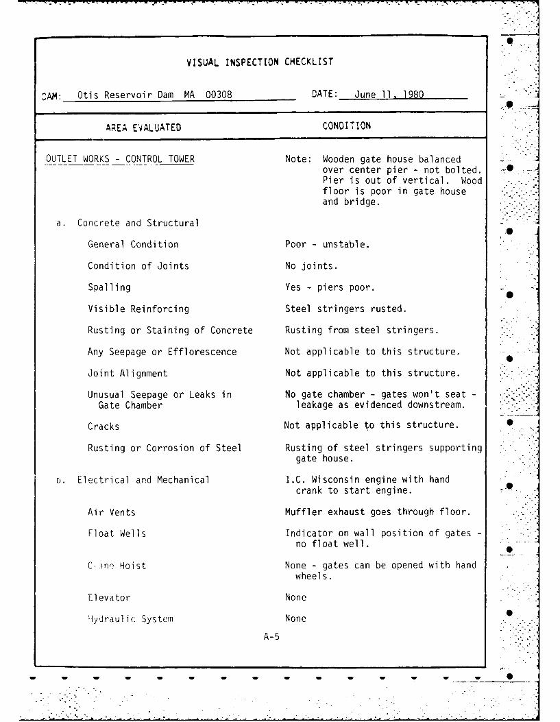
OUTLET WORKS - CONTROL TOWER Note: Wooden gate house balancedover center pier - not bolted. -Pier is out of vertical. Woodfloor is poor in gate houseand bridge.
a. Concrete and Structural
General Condition Poor - unstable.
Condition of Joints No joints.
Spalling Yes - piers poor.
Visible Reinforcing Steel stringers rusted.
Rusting or Staining of Concrete Rusting from steel stringers.
Any Seepage or Efflorescence Not applicable to this structure.
Joint Alignment Not applicable to this structure.
Unusual Seepage or Leaks in No gate chamber - gates won't seat -
Gate Chamber leakage as evidenced downstream.
Cracks Not applicable to this structure.
Rusting or Corrosion of Steel Rusting of steel stringers supportinggate house.
D. Electrical and Mechanical I.C. Wisconsin engine with hand
crank to start engine. -
Air Vents Muffler exhaust goes through floor.
Float Wells Indicator on wall position of gates -
no float well.
C, ine Hoist None - gates can be opened with handwheels.
Elevator None
ydraulic System None .
A-5

VISUAL INSPECTION CHECKLIST
CAM: Otis Reservoir Dam MA 00308 DATE: June 11, 1980
AREA EVALUATED CONDITION
OUTLET WORKS - CONTROL TOWER (cont'd.)
Service Gates Two 36" x 36" - used to regulatewater elevation.
Emergency Gates None - Stem guides binding due tomovements in pier for gate house.
Lightning Protection System None
Emergency Power System None required; gates can be operatedmanually.____________
Wiring and Lighting System in OK. Lighting only.0Gate Chamber
A-6

VISUAL INSPECTION CHECKLIST
LAM: Otis Reservoir Dam MA 00308 DATE: June 11, 1980
APEA EVALUATED CONDITION
OUTLET WORKS - TRANSITION AND CONDUIT Note: Leaks down through roofs ofstone conduit 20' upstream ofconduit outlet.
General Condition of Concrete Stone masonry conduits - not concrete.
Rust or Staining on Concrete Not applicable.
Spalling Not applicable.
Erosion or Cavitation None detected
Cracking None detected; one stone dislodgedand repaired in 1956. Strappedwith steel.
Alignment of Monoliths Not applicable.
Alignment of Joints Good alignment of stone conduits.
Kniibering of Monoliths Not applicable.
A-7
- w - ww -

t I
4U
, _ ..._ .T..=:_ : -Il- ; ; - i-. .
- -t- h - -- -
11
- , I !
"11
-• 'J . . . .i- i

S~.. , ii..
43. . .
.1
-- - .
o L.--- I. ..-I . I .- *.t
4 . . ~j.
F ~- r-. -
o :z < .0.. .9'*~ N
* LL' . [I V,.. - I'
r-~ ;.;~.-~ -.- . I.- - *- S
* - I---- I . <V
1')* ~.L.
I> _ ~II
_ 521
* ~ i1-~ - J. -7
* VI U. 0
- I.-~ *r..-~
.1g. uJ
K K ILlI -
K-
5 I82-5 S
.4
U V U V U U U U U U U U U S
- . . . . - . - . 4

. - -- -."-:- .::::-"- -
l "
"-+ A__\C
--- - . -- -d..,_ "
rI I ,
"t .i ' .:," .
* . -,-,- , , v "7 "
--- -. /. . .
B2-4
w -, .w .
* 1 ..
-- --. --
"
.. . . .B2-4 -
I .. . .. -"-
U .. , . "- U U" U . "S

. C - .. - - , .- ..
I , -.
TJ ,VIE\J. .,A+ •.+
.. .~
~ . ,* -- *~-.~-
. i s". ,,+u T. '/ +A.Lf C . . K. . *
.82"-3 P A '"
-- + j ... .. _
S SSS , .UU • S

-2-
,s. Deut. of Public Works Underwater Bridg-e Inspection TeamV Inspection Report Sluice G..tes at Dam/Tolland Road Otis Reservoir,
jtis 4/i"1_. (Continued)
The seal is effected by the tight fit of the steel plateagainst the smoothly finished granite header and vertical supoorts.
Then in a closed position the gates appear to be held inplace primarily by water pressure. The only Guides for the gates __
are four (4) three (3) inch diameter bronze wheels which are anchoredto the leaderswith a steel rod at the top vertical edges of the gates. ..
The gates are seated flush on the invert with no apparent leak-age. However there is some seepage at the sides and top.
A sketch of the gates is attached.
Sluice"2ya
The sluiceways which are constructed of granite block, wereinspected from the downstream side of dam.
The dimensions are 63.5' long by 2.5' square.
There is a row of granite blocks which seperate the two (2) .sluices. One bloc! in this row (Six(6) feet from the gates) apparentlyshifted but was subsequently repaired. The six (6) steel straps whichhold it in place are in good condition and the block appears secure.
The sluices are free of debris.
Attach. / .JOSEPH P. DONAHUE 0
Diving CoordinatorMass. DPW
B2-2S S S W -W -- o- .--
.......................................... .........-..

Mass. Dept. of Public Works M FUnderwater Bridge Inspection Team
U/W Inspection Report
Sluice Gates at Dam/Tolland Road
Otis Reservoir, Otis4/16/l0
The Department of Environmental Management has th c'
responsibility for the control of the water level of Otis --
Reservoir, Otis.
V'hen the Reservoir is at capacity the water Leievationis lowered by opening the Sluice Gates located at a dam onTolland Rd. at the head of Southwest Bay.
0The Operators of the dam experienced difficulty in closing
the gates. DE1 contacted our Department and requested an under-water inspection.
The following is the result of that inspection:
Trash Catcher
The Sluice gates are protected by a timber trash catcherwhich extends from ten (10) feet above to twelve (12) feet infront of the invert. The trash catcher is constructed of2"X4" studs laid on edge and is twelve (12) feet in width. Thesloping section of the structure appears to be in good condition.
The divers gained entry to the sluice gates by swimmingbeneath the trash catcher through its open sides.
Debris
A four (4) foot length of 2"X4". timber was wedged at a 450angle against the northerly sluice gate. One end of the boardwas buried in the bottom, the other lodged into the reinforcing""of the gate.
This timber probably caused the difficulty in the 'operation %of the .ate. It along with other wooden debris that was locatedbeneath the trash catcher was removed.
S].uic C ht' t,
There are two (2) seporate sluice opcnings which are eachtlirty (00) insh r square.
The gatcz ire thirty six (36) inches square and are cons-trwctcd4 of o; o (1) inch thick stoel plate which is reinforced-
i t • 1' "')
B2-1
w' ]w 2- -', "' w S
- --. . "

- -
PREVIOUS INSPECTION REPORTS
A. Massachusetts Department of Public Works, Underwater BridgeInspection Team, report on Sluice Gates at Dam, datedApril 18, 1980 - attached.
B. Inspe(tiorns of dams were performed by the Massachusetts,partment of Public Works, District 1, and reports are
16nn file at District I Headquarters, Pittsfield-Lenox Road,L,nox, MA - Selected Reports attached.
Earlier inspections of dams were performed by the BerkshireCounty Engineer for the County Commissioners, and reports arefiled at the County Engineer's office, County Court House,Pittsfield, MA - Selected Reports attached.
P2 --
APPENDIX [B-? ""
* 5
U U U U U U U U U U U UP U l U --"

-.- , -•..s-, -
r
LIST OF AVAILABLE DESIGN -
CONSTRUCTION AND MAINTENANCE RECORDS
A. PLANS AND SPECIFICATIONS - Plans and specifications for the Soriginal 1866 construction were notfound, although 1887 plans and des-criptions describe the as-built con-ditions. 1888 plans and specificationsfor modifications and improvements tothe dam are also on file with the Berk-shire County Commissioners, CountyEngineer's office, Berkshire CountyCourt kuse, Pittsfield, MA 01201. A1956 plan for regrading the top of damis also on file with the County Com-missioners.
B. DES'GN RECORDS - Descriptions filed with the County Commissionersof the 1888 work include some design data, but -
actual design records were not found.
C. CONSTRUCTION RECORDS - Some records filed with the County Commissioners. 0
D. MAINTENANCE - Recent maintenance records are on file at the offices ofthe Massachusetts Department of Environmental Management, -Division of Forests and Parks, Pittsfield State Forest,Cascade Street, Pittsfield, MA 01201.
0APPENDIX B-1
. ... .-

APPENDIX B
ENGINEERING DATA
B-i. LIST OF AVAILABLE DESIGN, CONSTRUCTION
AND MAINTENANCE RECORDS
B-2. PREVIOUS INSPECTION REPORTS •
B-3. PLANS, SECTIONS AND PROFILES
B-4. BORING LOGS
- -. . . .-. .

. .'-'I
VISUAL INSPECTION CHECKLIST
CAM: Otis Reservoir Dam MA 00308 DATE: June 11, 1980 - "
AREA EVALUATED CONDITION
OUTLET WORKS - SERVICE BRIDGE (cont'd.)
Approach to Bridge Poor transition with pavement; graveleroding behind abutment.
Condition of Seat & Backwall No backwall. Seat okay. Concretepoured around ends of stringer. . .
Note: Transverse cracks in pavementover bridge correspond tojoints in bridge decking.
* _
* S
A-12
W~~~ W W W W|

-. - .~~7 -;,- - q 7 7 --7 C., z-j----------- -r- .~C -U
VISUAL INSPECTION CHECKLIST
CAM: Otis Reservoir Dam MA 00308 DATE: June 11, 1980
AREA EVALUATED CONDITION
OUTLET WORKS -SERVICE BRIDGE Includes Tolland Road Bridge over
spillway.-.
a. Superstructure
Bearings None-stringers are used on masonry.Concrete was poured around ends of:
- stringers. TAnchor Bolts None visible.
Bridge Seat Okay - stone masonry at abutments;concrete at center pier.
Longitudinal Members Rusted - need maintenance10 - 12" W F @ 21 feet O.C.
Under Side of Deck Steel decking rusted.
Secondary Bracing 3 sets of lateral braces need main-tenance.
Deck Steel deck rusted -has bituminouspavement on decking.
*Drainage System None -over side.
Railings Okay-steel beam rail.
Expansion Joints Filler type-ends only; stringers.continuous over middle pier.
daint None -rusted.
b. Abutment & Piers 'General Condition of Concrete Satisfactory.
Alignment of Abutment Okay.*
A-11

VISUAL INSPECTION CHECKLIST
CAM : Otis Reservoir Dam MA 00308 DATE: June 11, 1980
AREA EVALUATED CONDITION
OUTLET WORKS - SPILLWAY WEIR, APPROACH
AND DISCHARGE CHANNELS (cont'd.)
Trees Overhanging Channel Yes
Floor of Channel Bedrock irregular and fractured;drops off 200' from weir.
Other Obstructions Debris, stumps, fallen tree
A1
I| ,
w~ - A-IO- - -

VISUAL INSPECTION CHECKLIST
CAM: Otis Reservoir Dam MA 00308 DATE: June 11, 1980
AREA EVALUATED CONDITION
OUTLET WORKS - SPILLWAY WEIR, APPROACH Note: Water approaches spillwayAND DISCHARGE CHANNELS between abutments of bridge
over spillway.
a. Approach Channel
* General Condition Okay - one 12" wood flashboard withplastic membrane on upstream face *of weir.
Loose Rock Overhanging Channel None - riprap okay.
Trees Overhanging Channel Not a problem - 30' upstream ofbridge opening.
Floor of Approach Channel Gravel and cobbles- okay.
b. Weir and Training Walls Concrete poured over stone masonryat center pier.
General Condition of Concrete Satisfactory - concrete has minorspalIng at stone masonry interface -
at center pier.
Rust or Staining Yes - from rusting bridge stringers3 above. .
Spalling No.
Any Visible Reinforcing None
Any Seepage or Efflorescence Masonry weir - minor seepage in joints J0of stone and around flashboards.
Drain Holes None - formed concrete repair in faceof spalling weir.
c Discharge Channel S
General Condition Natural - needs minor maintenance - jwork. . -.
Lose Rock Overharjing Channel Yes
A- 9
V~ ~~~~ lV W

VISUAL INSPECTION CHECKLIST
CAM: Otis Reservoir Dam MA 00308 DATE: June 11, 1980
AREA EVALUATED CONDITION -*OUTLET WORKS - OUTLET STRUCTURE 2.5' x 2.5' stone conduitswith stone-& OUTLET CHANNEL block septum.
General Condition of Concrete No concrete -cut stone masonry blocks
*Rust or Staining No
Spalling Not applicable.
*Erosion or Cavitation None detected.
Visible Reinforcing No - stones in conduits repaired-bolted together.
Any Seepage or Efflorescence General seepage in face of dam inarea of conduit outlets.
Condition at Joints Mortar washed out of joints - mortarweathered; vegetation growing inI joints.0
Drain Holes None -seepage through joints.
* Channel
pLoose Rock or Trees Overhanging Stone masonry retaining walls-Channel northerly wall is collapsed.
*Condition of Discharge Channel Channel needs to be cleared of fallenrocks and trees to remove backwater. --~Cut back trees in danger of fallinginto channel.
Note: Concrete and steel "Fish Trap"120' d/s no longer used. Footbridge is vandalized.
4 A-8 N

Li MASSACHUSETTS DEPARTMENT
OF PUBLIC WORKS
3 INSPECTION REPORTS0
APPEN4DIX B-2B
B2-7

" : L-l 0, " ' ; F'
INSPECTION REPORT - DAMS AND RESERVOIRS * '
-' 1. Location: fU/Town OTIS. Dam No. 1-2-225-8..
Name of Dam Otis Reservoir Inspected by:R gord-plovej .. "
Date of Inspection 5/13/76 .. 0
2. Prev. Inspection xOwner/s: per: Assessors_________
Reg. of Deeds Pers. Contact____________
-" .1. Depaetment of Natural Resouaes B Boston, MA ',,
Name St. & No. Clty/Town State Tel. No '
2. Na1me -_'o.City/Tow " State Tel O] . . .. • - -
3.
, Name St. & No. City/Town State Tel. W.0 "
Caretaker [if any] e.g. superintender.t, plant manager, appointed by absentee .,owner, appointed by multi owners.
Gilbert Bliss Cascade St Pittsfield, MAName St. A 1io. City/Town StaO Td. "!"1 0
,_. _ _ , . . .: , . - ..:.4.
No. of Pictures taken 2 -
5.Degree of Hazard: (if dam should fail completcly]*
I. Vinor . . tloacratc -AllX. .
3. Severe__ 4. Disastrus s• .' .
*This rating may change as land use changes [future development]
Outlet Control: Automntl . 14tnull X......Operatve x yeso.
Comments:__________________________
up)Lrxam race ot Dam: UOldltl(1nn:
1. Good X . 2. Minnr Rcioalrs .
3. i'ajor Repairs . 4. Urgent R-p~1r';.. .
Commcnts: '___"
G2-8
S S S S S S U w w w

* - 2 -DAV. NO. 1-2-622H6
D ovr,,stream Face of D.;n: Corndin: 1. Cood X * 2 Minor Reairs.
3. f1a~or F c-oairs 4. Urgent Rcpars.
Conil~zts:
*Emcrgency Srillway: Condition:.]. Cood x* 2. Minor Rermirs ..
3. !IaJor Repairs .4. Urgent Repars,~
ConwrtG:
I-ater levwi 0 timt. of inspection: 3 .ft. abrovc -. below-&-
* tor of damr~ 0
orirncip&l spi*-.. L-.---.. -- -
rut hc.reergecy piv&Y...............
Growtth rrrccs and Brush] on Emt~nkmcnt____________
LPAnirtl Currcq-,s i.nd 1Wa.SioutS________________.
Oarnagc: to slopes or toni of dam____________
Cracf:cd or 0: mag~d Masonry_________________
Evid.jnce of Sccpagc__ ____
Evldenct of Piping 0
Erosion_____ __________
Leaks x
Trash aind/or dcb~is inIPL~inq flow _____-
Clogq'd or blocked srillwy____________
Othe~r - ___ _ _ _ _ _ __ ______
B2-9

7 71
3 DAM NO. 1-2-.2
- ,?. Remrks t Pccomiendations: [Fully Explain] PREVIOUS INSPECTION DATE: July 11, 197.t
In general, the dam appears to be in good condition. The brush at the toe has been .
removed and the area is accessible for inspection. Of the five leaks reported in
S. 1974, only one was noted. It is located approximately 60' northerly of the dravdou .i
-. gate, at the toe of the stone masoney wall.. -.
.-.- The upstream irace of the dam and the emergenoy spillv.e7 are in good condition. -.-
-. For location see topo sheet 6-B.
1. " -af.
Mi o 'to- r '" &" " ~
4 U..
I. .
.o4
d r 3 from i.-c.- list
.2-104. ,safc_______________
13. " 2O10

L-66
INSPECTION~ REP0RT -DAMS AND RES RVIR&
1. Location: -UTT/Town OriS . NO
Name of Dam Otis Reservoir . Inspectedb:
Date of Inspection
2. ~~~~Prey. ;nsptction.....LJJL4... X,Owner/s: per: Assessors.
1. Department of Natural eore 12 Ashb2~'t St
owie. poite y u Nio.ne-inName~r ni. asae/ ftaT.~ &
3.3
1r. appinoed by mu.t owr'
flamee St 713 jt )4eI7T
*This rating may change as land use ChAngi Esu
Outlet Control: Automatic . Manual~ .. ,J
A. ~~Coiments:__________________________'pit
1. Goo I .to
Z1.
___ _Op_ A M
3. Pao Rear 4. U U U Un RU U

L-168 A
2 -DAM1 MO. I -2-5~
Oovnstream Facc of Dan: Condition: 1. Good Mi. nor PRepairs
3. Mlajor Peoairs X 4. Urgcont Rcna irs_
Conrcnts: See report. -
IAEmergency Spillway- Condition: 1. rtoad .2. Minor Repairs
3. "aJor Repairs .4. Urgent Repai JkCoryments: None
& iater lcvil 13 tOn of insprction: .2 ft. abovc below ,.
tor. of dam .. ~ ..
nr1icipo1pllw
othu.r_______________
Jummary of DccnciLs Noted:
Crow.tlh [Tr, i5s and Brush) on Erbtnkrwnt__________________
Animal EPurrc'fs ind Pesuiouts
ODrnaq, to slov..,s or ton of dan- '
Crac!'.ced cr O.'rig _d ! tasonry_________________________
Evidnc4. of S..Praqc
Erosion__ ___ ____________________________
Trash ai)d/(r debris lmocding flow-___ ______________
Clogqcd or 'locked- srT11w.3y
Othtr__
632-12

-3 DA, NO.1-2-42 "M
(- 12. Re2marks , Rccot, rndations: [Ful-ly Exrlain]
On inspection of this structure a very severe condition was noted along the.
stone masonry wall on the downstream side of the dam opposite the gate he•,s4.
Water was flowing in relatively large amounts from appreximate1y five area
along LhIs wall Indldi ti, Lho potioibiliLy of piping through th strvutuO, . .
Because of the size of the reservoir this situation should be attended to. ,-di - .-
and whatever corrections that are necessary should be made. ......
Also there is brush along the base of the dam that shou.i be cleared awa.
A description of this structure was submitted in 1972., , . , .
There are no changes to be noted.
For location see Topo 6-B. . * ,;,
0
3. Ncrall Crnditi n:.
S. S f. . .
2. Minor repairs needed . " - ..-
3. Cnnditinally safu - major repairs neoded .
4. Unsafe
5. Rscrvoir impoundmcnt nc longer exists [explaln]
Rconmend rumoval from insrection list
B2-13 .
L" W

INSPECTION REPORT - DAMS AND RESERVOIRS
1. Location: City/Town OTIS Dain No. I-2-2 35-8
Name of Dam Otis Reservoir Inspected by: R D Jordan "
Date of Inspection 11/13/72
2. Prev. Inspection __..._'_'Owner/s: per: Assessors
Reg. of Deeds Pers. Contact_ _ _
- I) N R 15 Ashburton St. BostonName St. O No. City/Tov-n State Tel. Ho.
2. .__ __ _ _ _ _ _ _ _"flame St.T1. City/Tovn State Tel. No. " -
3. _-__ _ _ _ _ _ _ _ _-_lfame t.-- Wl~. T i~ty/Town State Tel. No,
-3 ..
Carotaker [if any] e.g. superintundent, plant manager, appointed by absenteeowner, appointed by multi owners.
Bilbert Bliss Cascade St. Pittsfield
flame S$. & 11o. City/Town Stat' Tel. No.
4.No. of Pictures taken 3
- . . . .
Decrec of Hazard: [if dam should fail completcly]*
1. Vi nor 2. I'derate I . 0
3. Svver. 4. Disastrous____________
*This rating may change as land use changes [futurc development]
Outlet Control, Automatic Manual x .
Oprative x ycs" no.
Coinents: . . . .
7.
Upstrcam Fact of Darn.: Condition:
1. /'ood X 2. M.inor Repairs_____
3. 'ajor RcPairs . 4. Urgent Repairs .
Commcnts:
62-14
" . .... ...

* L-168 A
-2- DA .012-V
Oo'nstream Ficc of Daim: Condition: 1. Gloo~ 2. Minor Renairs__
*Emcrqcncy Spillwy Condition: I. -ood X 2. Minor Rerairs____
3. "'ajor Rerairs .4. Urgent RLPalrS
Comments: ___________________________
l(Atcr low 1 0) tim of insp*-ction: 6 ft. )!.)v(,-. bclowx .
ton of dam xl .
nriocipal spillwaiy________
0 thk L
11. 0Summary of Dficiencics Noted:
Girowth [Trk-es and Brush] on Embankntwnt x
Animal FPurrcwvs i.nd Wa'shiouts_________________
Darnaac tn slopes or ton of darn __________________
Cracf:cd or Dimaged flasonry______ __________
EvidonciL of Scepagc ___________ _________
Evidencc of iig____ _____________ _____
Erosion___ ____________________
Trash and/or debris imncdinq flow_____________________
Clogqcd or .blockedi sr111~jy_____________
Other______ _______ __
B2- 15
v w

L-168 B3- DAM NO. 1-2-2-15-8
12. Rk;mirks Plconmkndations (Fully rxrlain]
K Dam appears to be in good condition. Some minor seepage was noted at the .O -
spillway. The gates were open for the winter drawdown. The brush at the
toe of" the itorie masonry wall nhouId he cut bnck. Other then minor brush
- cutting the dan is well maintained.
13.fv, nil I h ril t i°
S"fc_ "x
Minor rk-p',ir'; noi&d
3. C3r.diLitw'ly s.)fc nijor r(txLirs needed
. saf_ _"____
5. Pdsrvir impnund t nv lonq r (.xists [explain]
Rcommcnd r-movil from insr.cction list_______
B2-16 -
W a W 0 0 0 0 0 a 0 a a -- 9

L-69rESCRIPTION OF DAM 707-
DISTRICT ONET
Submnitt~d by_ R D JO JDAN DAM No. 1-2-25.-8
[3at__C i Ct v1T: wn OTIS
.amc of Dam OtUi Reservoir
Locatic~n: Th-r. Shicot No. 6-B___
Provide 8-1/2' x 11" in cl- ar cony of :opo map wlti location of Damncl-arly indicatc-d.-
Yccar built: 1888 Ytar/s of subscnunt rcpairs 1959
Puroose of Dam: IIoter Supply .Pecrcational X
I!rri qplticn ____Other________________
Dr~ir'~qc Arca: 17 _____sr. mi. acres.
Noniw~l Pon'dirn, Ara:_j96 ______cres; .'".vc. Depth__________
lmnoundmcnt: e.s;acre ft.
* 6.0
No. and tvp : of dt-,Lllings locatcd adjacent to pend cr ras,-rvoir-i.c. surmrl.r omcs ctc. _________________
Dirxnsions of Dam: Le~ngth 625' . "~ax. Height 31'
Slojp s. Upstr,.,m Facc riprapped earth 2/1
Cmtnstreom Fac-z stone masonry _
Width ncress top__ 28' ____1_
8.Classification of Damn by i'aterial:
Earth .Conc. lipsonry .Stone Masonry .
Timber _____ R-ck f i _____ Othcr.
A~. Pci-tc f r'rfcsznt lane, usi(c, d~onstr~.am of dam: ______
100 %rural- % urban.B. is torr a storaOL err oar flood plair dctwn trcam of ci~m which could
accrmned~itc th, inpoundrncnt in th,,i evct~t of a complcte d, m failureY~Nc -. B~___ 2-17
6~~4 a wS

L-169 ADAr NO. 1-2-2.5-8 -
10. . .Pisk to 1ift ind ;ron,.rt'/ in VLIt Cf complCtC failure.1,A):it of UIQ~ c.okiid be mfoderates proprty
*io. of F .ol(_ damage could be quite severe. Water wouldeventually pond in cold 3prings Reservoir
C). of 4omcs , Conn. line.
Ir'. cf Businesses, ___ -
No. of Industrids . Type_
No. of Utilities Type_-.__
RaiI road .
Other dams Cold Springs Reservoir S
Other Route 8
Attach SLtch of dan to this form shoi,inn sLctin and nlan on 8-1/2" x 11"sheet.
B2-,18I% i
0i "i>
" 0
B2-18 ' "
I
6 S 0 S S 0 6 S 6 S S"

%'~T Cow L Bob' tCo%%o -rot a%- 0okt
*#too"
B2-19
4pS

I VI
*
S IRpZ
* AA
00
/1\/~' ~ e'%
11
A- .rA-
, 0
I 1 4
rrL ,s (A L A '0 ,; 7
b32-20

Figure 3 - View of top of dam looking southwesterly. Note woodengate house with gage board attached to concrete pier atcenter of gate house. Gate house is balanced over Icenter pier. Abutment piers for access bridge providestability for the structure. Tipping of piers towardsthe reservoir indicates movement. Note riprap at up-stream face of dam.
mI* 4
Figure 4 - View of downstream face of dam lookirg southwesterly.Note low point in top of dam (Tolland Road). Low pointis intended to act as an emergency spillway. Note stonemasonry wall at downstream face of dam.
C2-2
0 6 0 0 0 6 0 0 6 0 0 0 _

Figure 1 - View of top of dam looking northeasterly along TollandRoad. Principal spillway is beneath the bridge in the i -
foreground. Gate house is the wooden building to theright of top of dam. Note puddled surface water inpavement depression.
Figure 2 -Photograph of a photograph taken when reservoir was drawndown in 1956. Photograph is on file at the BerkshireCounty Commissioners office. Note concrete pier support-ing gate house. Also note gate stems attached to concretepier. A wooden trash rack is in front of the gates.
C2-1
S 0 S 0 S 6 6 0 S!:

dL z
II~~ 0 Z-0 ~ ~ o
-' Z1 a.0 z. 4
C2 o ox c
Mi K± U)
0- a 1 03
a w.
-- z
I X!>~ I.- I
U)
-J .'0 0
.344
.JL&
Lz

APPENDIX C
PHOTOGRAPHS
: -. O 'iRAPH I N EX ___1___
C-2. SELECTED PHOTOGRAPHS
w W- w w0

TYPICAL BORING LOGS
A. None available
lp 0- 4p 0

ISMjoe 10i t UORAW ud
o 0 Ls0
o0 0 L 0
a - 1. h
a. a. lK
a 0 0,63.o- '
*~a U.) -03 lu 0o
Iol 15 -0: I
000
az a
16 00 04 0 0
22 Do- ~ 4a
0V 1/ CID~3 I
22
-- c-x I U. a
*.- Oh *!00
4000 -- I
a.a
ILM

00
- J.
IL~ a: Z
e-j IL 40-Sa *a
HijI00,
Aa
6---
a Z,
A__ 0a
4
00.
Zx 0 ZC
444
Wa
111 0
00
ma z

-•. '.'.-"'•-.."-...
I- . ...
A. SKETCHES COMPILED DURING PHASE I INSPECTION SHOWING
GENERAL LAYOUT OF DAM, TYPICAL SECTIONS AND DETAILS
OF SIGNIFICANT FEATURES:
.0
Figure 1. General Plan of Damsite
Figure 2. Typical Sections %
B. RECORD PLANS:
Original plans not found. 1888 modification plansarc not attached but data from plans has been in-cluded on Figures 1 and 2 attached.
Akpll ['1X 5-3
0 w

NJ7-:
Berkshire County Commissioners
U Page 2.
to the elevation of the top -)f the maoson->. wal! ir tiie sec''o ,6k :'D1888.
I would recommend that a rnee-7'q e .e e rf; rese, -ite i' t-~*.
fhe dam, the Forminytor, River 4ate- PtK.ve Cc red 'e i' t e s-, ~orronge to t o ,e the iddltonal spi Ilwoy ca19 jc ;t, -'s r'Sc- r.'j.tkei helgH~ ond design, efc.
Rtspf-c'Ft L t)- ,. 0
Hory Ii. Heapl y, /t3Cu!t CO .'t)qnee
HWH/C0
H~L -I 2 'c

A- C ..to C.a..'w"n*rsJOHN F. SHEA, CHAIR.&.
THE COMMONWEALTH OF MASSACHUSETTSCLINTON J. POSTER
*CK8IOGX
JAMES A. BOWESMORIN AIDAM
PITTSFIELD, MASSACHUSEIS ELA. POD?,IS Ja. 0
HARY V. REAPHYLan
June 18, 1956
Berkshlre _on, C.orrmissioneri,Court Hl t
_ ,ewle-
:ie asr o made --) tf e 'jam at East Ots Reservo;r today in company with-'-K, -- ) rj~ -. o the Selectmen - -le Town of _)tis. At the time of our
s:t ei.e~t~dy weitth exception of the broo[. or channel in thec -nu" se por*os )f e escervo* whicii were parts of the old notural
*.,~, 'e.. ~ or sd f tnc oarn ihas a slope covered with loose rock itsInir r Kyr c t j- qo!s %I E'e tie, frasonry wal Is appear to be in good condition. No0
e ;dE -~e iss.. e :-< I, ', ilope )f any dlarriage whatsoever due to flood conditions of Augustond 19th, * _ -Ie gotes t~oae oieen iferied for severn! weeks past in order to draw -.
off the vwi'er so tormo epairs could be made to the two 30" x 30" masonry sluices or culvertsIna+ !(ejd tkte wte- to" th.e gaites under the dam to the brook below. Workmen from~ the -
Paimngtur R;Ve- '0 f we, Co. br'ught some material and equipment to the site todayp:repa. 7nc *ojr t.-nc in. nq c-t oe.f tihe stones in the dividing wall between the sluices whichhias beo rre Jr &)quye *:ri r.a5beem patiofly blocking the discharge of water from the gates.Ncyn ,rj0r retc! ofap)s ire to be used to ho'd and anchor the dislodged stone or stones in
it,'gn';' poosit', n r' r'-- o. j!1 /hen this repair is completed the gates are to be closed
6+ i --e wofer reaches spilfway level repairs are required at the northwest corner:!, sore aorrv eico< an and undermining has talcen place at the base of the stone
. t 'F#I rnte'h:l f. d ecurrposedl rock sh-ould be removed down to solid ledger w 'me h apffo~ed concrete footing. The northerly half of the spillway overflow
Nih~ oreeo. :p~s -oirring, e!' ., on~ he doA nstream face.
A srvey ',as been maode if the dar7 and -oad showing plan, profile and cross sections.ltocppec,-. th it 2 er tde years tie tro~el led portion of the rood across the dam Vias been raisedso thjit at preserit it is h~iher thaon originally desgned for. At the public meeting held attie dmry; ') hd, tern ber a), 1955, after he flood of August l8th-19th, it was brought out by
hke Arm> 'ny~reers that t'r' spillway capacity for this pond should be increased to care foru flood conditiori s .ck as we hrjd in August 1955. This can be provided by e&her a'meA sp~fl vm/ ;r ordithin, f thcp present one, or by cutting down the roadway on the dam
632-25
* 0 00 0 0 0 0 0 0 6 S

.. t of f 1 -1 *: . s . sl ! *) pro.eil
D.. ES1W r-,c
L r ai at%;> c tec-trzc Late 3tvW t- :1- 01c- -Cc .:tL a-r
o~~~~~zn rcc- rt"-- tQsC~'-t
1 , -(,F C 11 LeC-~l wt" *'e r! eu I
cr4 tC-L2 013 t tl r, nt(U c-t 1 t-c-c
cnT zC)t tEuti-L t.r- 1E t .- al -c d0-'-C- rlo -efltS t-lc ~ t ec i r ' o
cE. cxC (XI' v:~e n : f :I u-ce r~e - -- -
7' a- to be' -.; c -o - c- re1 zc "r- s a~ "-c' t -1 en ~ The o"-
t ~p t-LD be "t--- c t c
n o (~t~ ,f t rtc' a-y ln s t tli~e :a- et~ :;
J-t rc pie '-t r' to d :2 &.K
- ~ ~ ~ t- - D:. E-q a v c ute'a-ic~ nI- i
cc-- -te' bcac cf'he T t1 ~ ~ ~ ~ -C *-f- D.- n -, ' o c
1 C t bre ob t o rx n e 1 Ic 0
F de- 1 e, "D ld bE-.Ic- t tr c- ' i a-t. r-.- tc*
3.- Ct-Cl D- I u 3~c~
* ~~~~~~T -g2& c C-'OP-7.77
r-j-c~c ~ c~. L2-24c- 'i

-2--
mason-y wall was apparently built in two sections and as a resultis cuite mzssive. Old plans Indicate that for a height of 31' 7"I tre base of the mbsornry construction is 20 ft. wide. If detailed.vest!Eaticns that have already been initiated indicate that this
do-,wnstream rr -_orry wall is founded on ledge and is as massive aSshnown, it woald seem possible and practical to grade and pave thetor of the dam in tne central portion to allow for the overflow, o N
exce~zvestorrm water disclbvargeo
Thie p-:.i- _ si.-,ul be construa ted to ca-r the masonry wall to fra leak res-'stant jo-int at the upstrewir edZFe of the pavem-ent and
shudbe tied w;ell into the earth of the dam and the ri-rap of t'. eupstrear: slope to prevent flow of water under the paviLnE. 3-;'--ruse Of the-c to-) o" the da-. for a distano-e of about 330 ft. as an ei-ergency poverflo-: crest, it moust be remermbered th -t in tine of r-
trfz--. storrm flow, TollhnC Road wo'1d be temp raril1-r Cut Of scrvlce1.and- aocesS to the sila-fror, the northerly end of' the cam. ni-trequire approac-h fr: the so3uth.. Ordinarily, kowever with flow Ofwete r over theic re7raded Tolland RoLd, eqiuir.ent tnd-4 personnel CJ~L J
toai:safe>- cross the eme -ency sp: llwa:T area. l. rels-t*ve-shal~~ovcr'flzwin:r wter.
- - o-!strear o-' the stone we-Il there is an earth e-!-'--ner .o- vafr!Lable depth thiat covers tne natura-l ledge. Tr ti'~e ofover :10.-. is the emercency spiliwap this earthi coulcd be wLa-e4- av::.y.
u;-n ir-mi-:tion obtained durin - our prelimina-ry stua of t~lsj s1 hLi:h>- rrobable that th- stone maso)nry w-ll does rot rfc
I -tn fo)r stability. Ho,.-everl th e earth protec-ts tnie na-tu.ralle'-does p:rovide a resisting, pressure to any tendenr-y for tne
U 1 ) mc-ve outuard. In m17 o7p:inion it would be worth-whi e to pr-e-s r% -F e&a-t- [-rom washout in time of emergency ove rflow tc: ~&-
T ax e irrcedistel-y DownstreamTn of this w&.ll withl exce-r'4onallyeL J - ders L:ni ri-rap. The paviu; slould3 probabLly be 2 . or
irjre -i t:-c -E-s ans wo,:uld not of necessity be entirely rn- pLn66
eof 'r: inspectio-n of Otis Rese-rvoir, no ls or wtU ~0-ginaril, 32"1 of flazrncozrcs hnave been maLintained
It is 7:ru-6 tan-dlnE that the shoreline of Otis Rese;rvoir is uselfor c *~et ioral croesby many permanent citizens of Otisas elas s=,?r 4-'"re resijentzo I assime that these persons are all in-ter-ested in- maintannt- a given water level in orde-r to makfe u.1e Ofthei!, r-ec .ra -L'ial facilities. Since 32" of fla-snboar'is h ' oesu
~ -cat '4 ris danm in the past, the shoreline an(; relzate~ fiec'l-itir. , 9 ~l been developed .naccordance wl-tt this watelI
leVEl-. &e~~
When flbshboards are replaced on. the spillway they shud be kept aslo~as osi~s. -akin' into considerat-.znr the shoreline problems
involved. They should also be installed in such a manner that theywill easily fail andf be washed away when they are topped by a pre-determine-i dept h of discharge. This depth Ehould probably be 6ll to
1"to :nx!mum. over the flashboards. The overflow level beinFg governed
8B2-23
* %

WAEUPL TIGHE & BOND, INc. aMMl amIC11 SNEYALLAYIONU
meetaCONSULTING ENGINEERS IMan £"lfanUs
SEWASK CIEPODAL BOWERS AND PEWUOT STREETS wOUUIme DEVELOPENT
UTUUCTLIRAL £NUINI(UINO HOILYOKCE. MASSACHUSETTS 7-WAUTK IOOUL
£LCCTR.C.AL ENGINEZENO GORGE H. MCDONNELL .-
PHILIP W. SHERIDAN
k~~~~P t'- t d . . LGL.'e
U .fl .. c'. -
Tnt ~ ~ ~ ~ ~ ~ en _ th o.r fJy~ 7 Coze.:nr
ZI~~~~~ ~ ~ ~ e.4.; '-Y - ~
cr'J In~l EI '2r he -
4.- eI: CtQD 1
hClt r.-
-u- 6 c z.t
un~~erstnno~~~ing, (,scoc ne±:z t wr ocr.
r 3.- fC- t
tnt ~ ~ ~ J irarS'- -reE ocOts tseesr
o. -A ' t; ft the (t> DS. T
C3 tt.- I tf CL n. l- Z, tn 1r - , ,"z t sr i- t o v
-, t r C * e sC' w f. oe :er t n n
t - r~ . tr -- ' lsure- 1 e se. ,
e 1 p- c' o' 3Q r:-ci t-1; tn t o i c~~c occ-Id of t:, c_- be.pr &z..
0.-. )1t of±& p*- :l-,d o 0 Dtvnc:rd L ner- of tuthofcw& EocC E.1- o-, b-nthero~d pse'.
G-j. .. h4 entre ot o" tne of~ the tni. th sCtonesetin
B2-22

BERKSHIRE COUNTY ENGINEERS
INSPECTION REPORTS
APPENDIX B-2Cj
B2-21

- S
Figure 5 -Outlets for the two 30-inch by 30-inch stone conduits.Gates at the inlets of the conduits are controlled bygate operators in the gate house. Leaks in the roofs ofthese conduits were noted 20 feet upstream of the outlets.
. p
Figure 6 -View of the cut stone masonry wall at the downstream faceof dam. Note grass and small brush growing out of the joints.Wall alignment, both horizontal and vertical, is good. Seep-age was noted at the base of the stone masonry wall in thearea of this photograph. (See Photograph 9)
C2-3
,S S S

°.1
|m -
Figure 7 - View of cut stone masonry wall at downstream face of dam.Note small brush and grass growing out of joints and along .top of dam. Earth in foreground is banked up against stonemasonry wall.
Figure 8 View of the downstream face of the principal spillway weir.Note center pier which supports bridge. Note wooden flash-board with pins; also note 32-inch high flashboard slots.Steel stringer bridge above spillway carries Tolland Road.
C2- 4
* 0 0 0 0 0 0 0 0 0 0 0 0 0 0 W
. .. .. ,.
. .,. ....... .. .. .. "

- S
Figure 9 -Area of downstream seepage. Note seepage flow originatingat joints in the cut stone masonry.
Figure 10
View of partially collapsedstone masonry retaining wallon north side of dischargechannel for the two 30-inchby 30-inch stone conduits.
C2-5
* ,°00%"0 0 0 0 -0 0 S

* 1
* .... _
" IF
0 .
Figure 11 - View of fish trap located about 120 feet downstream of
outlets to the two stone conduits. Note steel screensand foot bridge have been vandalized.
-,5S
*Figure 12 -View of the channel just downstream of the fish trap shownin the above photograph. Flow in this area is primarilythe result of leakage from the two 30-inch by 30-inch conduits.
C2-6
'S S S S S SS7.7 S

~ Figure 13 V iew (looking upstream) of the outlet structure for Big Pond.Note that this structure is not a dam but is only a levelcontrol structure. One half of the Otis Reservoir watersheddrains through Big Pond.
-L.
Figure 14 -View (looking upstream) of steel stringer bridge on the westbranch of the Farmington River just downstream of where theFall River enters the west branch of the Farmington River.
C2-7
po -.
.
_
.,' .-- .
•
°. %:
Ip~~~ ~~~ I" a-

S..
Figure 15 -View (looking downstream) of the steel truss bridge on Route 89 in the Village of New Boston near the Junction of Route 57.
Note building to the left of bridge which has apartments, storeand post office. Structures in this area would be severelydamaged or destroyed and a loss of more than a few lives couldbe expected as a result of a major dam break at Otis Reservoir.
C2.-8
* 0 0 0 0 0 "' 6 -.0 , 6.6
APPENDIX D
77----
HYDRAULIC AND HYDROLOGIC COMPUTATIONS
D-1. DRAINAGE AREA MAP
D-2. COMPUTATIONS
r7 -7
w w w w w w -w w w w

Robert Br'nwn & Associates, ;nc.t 1T 1 OF 0
ii~DATE r. C
~Imc -.~- DATE - /o~
N6A
r'0 ~- I )1
~e '7S CLkeo ->w'J~ > (iTrci
U, v k C C -f- CV AA- 'jL
; I i0
z. -
A:-
K) w~ . w
70

' Robert G. Brown & Associates, Inc.Berkshire Common - Third Floor North 2OF -- 0PITTS"E[D. rMASSACHUSETTS 01201 ,:AoU1LATE0 HY VATE~ LIP
j413) 499-1560 CFKBY J'C-
SCALE .
- occ V/- f" -iF 58o & c c
USGS Gn- l~o W)es+ 1?S-~~~~~ 5~k- -. ~ i~ - 3,0 oo
CCZ '.~' 2\Te 0 c"jY' cYW' r c
A
0, 4 45 0 4zzIQz 75;~ )Q z 1 . .
W W W Wj

'Robert G. Brown & Associates, Inc. -
Berk-h it- Common - Third Floor North SHEET NO OF- O
PITTSFIELD, MASSACHUSETTS 01201 CALCULATED BY D A__ ATE 6 /(413) 499-1560
CHECKED RY - _ _ DATE
SCALE
Q
_,-- Y) . -
- . -.
- K \ - -4-63.
MN N (') 117 r.
'- - - N , "rA L "I "
-,4 ( , , ,) -'
\ j V- ") -
1 ; O -, -- ._ _ .. 1...
_ - "- -""
[SO. ,o "-- "
.- .-. .-.-- ~- : : - *.-:.-- . - - - .... ........... . .. .......- - - .-
. ' t' ... " . -.. " A
• 7T%
0: !.. ..- . -r 3 ._ - .. . : ":.\4- "
• . .
i: o ... : . :; . . .. . .., . ' " " - ' '
I nln l l ~ l m i l nl l . . . . . . . . .. . . . . .. ... . .. . "->-

-~ -.-- I.-7-~- -~ 0 *j
_ I A
U
I * -~
- .... . , . 2
~ ~j-
~0
U,
I , .ou
.0 0- I
- I..
II '3-7 - .
0
$~ <1< U
- j1~-fI\
0~
N 0
'.4N
p
. .------ C,I' 0 S
c-J
I.' -I.',
*
* S w ww w w w w w w w S
- . -

'Robert G. Brown & Associates, Inc. -B :--Berkshire Common - Third Floor North SHCE NO OF
PITTSFIELD, MASSACHUSETTS 01201 AL ULA. BY _ DATE ?Lu 4"50
(413) 499-1560 C FCLTD Y . . ".DT .2-CHECKED BY 0 . . . ATE__ - ---- 9 ,.- )-
SCALE -- '
A, A,-142?- IO1000 - 12-OcQ Presevl4
J''z 1100 at'Q2,2 ~ TO
14ZD 11 , (000- 250
14' O oo \Au 1 rc saZw>O cCeiAO PI k 10re -1".
e & P 0v C0v Wz - a xV 10" Ac 2 000 f- A.'s e
7 / S// ,-
14 o - ... . .. .... .. .
* , -f:z.,...-- . ----- -
• V) ii: <
. 4. . D ¢( % )' - -
.L: . . . .
!, Wl Wl W W W W

................................................. V S
. S~2r >.i-'A . j
4'.~JI..'~ I . -- 'N
4;-J
* N
Lii J-
I~J
i-U 7
K0
- ('I N
k SN
Q-)* . I-
0~V)
KN SN
0 - i-------~ - S4'
6'~
(
S
0 w w w w w w w w w w w w S
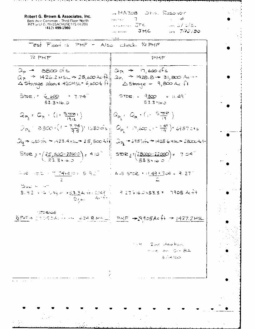
Robert G. Brown & Associates, Inc.Berkshao Common - Third Floor North -PIT Dr1lL1D. MASSACHUSETTS 01201 ;-7AT' ... / /
'413) 499-1560 AITE
A,
~+ F~ci ~& ce -2 2PH FV 2
'/ 14 -F Z P
0 )
"42 "ZZ 2',64l-/-. & , !-f3l xA-'-
,.,p' -~~ 7,7"o-.IL b' 4" " L _ S.w' e q)z ~
. -
3,3 A' 2 513. 3'JA0
r ,
K '.
: -,,-wS Ot! i''e 2o,' .
-,
22 ',(I. oY
5,~~~~ W 2 W ~ $.A~-C?-' -~£ ~'S. 15Ai

AD-R154 695 NATIONAL PROGRAM FOR INSPE CTION OF NON-FEDERAL DAMS "2/2,OTIS RESERVOIR DAN MA .(U) CORPS OF ENGINEERS WALTHAMMA NEW ENGLAND DIV AUG 80
UNCLASSFIEDE/G13/ N
INE

1,0
1 014
1*21 1* 4
-B -i 1111.1
- ,' IIIIIN
NATIONAL BUREAU OF STANDARDS.. ,- SLt L M S CHART
: IIII\*.. s . ."--

" 00~~~JO H A 3ae, o4,,s. Emu-,,,12;r- "-.. > .
Robert G. Brown & Associates, Inc.Berkshire Common - Third Floor North SHFET NO - -- "__-- . ..OFPITTSFIELD, MASSACHUSETTS 01201 CALCULATED DV.. ATE /1d
(413) 499°1560C
SCALE.-
; ~ulc 4z i. ,.Ioo c(s 11) 00 cps, :- a " 5. L- 14 Z S H I
?(Q~o)(sL) 4If.*, SZ ' fla £ .-,,.,-,-.!~~ep~2 fOeop .3 A.. G~
wan 24600-" " "'
; Q : C z~~L . ,o )(3& ( ,9) Lc - s -,, , ..
B_ "
•~~ -6 :. Ji . .
.D2-7
1i W> ''- 2..- ' W

Robert G. Brown & Associates, Inc. JOB~~~4
S e~or
Berkshire Common - Third Floor North SHEET NO 24OF 9PITTSFIELD. MASSACHUSE17S 01201 CALCULATED BY________ DATEZLJ~
(413) 499.1560CHECKED BY DATE ________
SCALE
2.4 (~ea10-) )~lsv-U-Q~: ~ i- ~.): 3I~c~ ~~: rco C- ror):
55 CO-2fO 3,9 S~r~s 27~C' 13 14'
5u$4o +c,3q 2 2 z: 5.390 Aue-Sar -7.jZ~ 85)
"'G a-1 2l A,) - 14 4, HSL ?HF--T20(2a7A&-P+-- 142(v,5W5L-
o 't rfto V1 0+ S 1 v p4'i aIi,
92..
* * U U U U U V2-8

-.:-:
Robert G. Brown & Associates, Inc.Berkshire Common - Third Floor North SHEET NO 9 OF I, . ,,
PITTSFIELD, MASSACHUSETTS 01201 CALCULATED BY ,Z__ _ _ DATE I /--'(413) 499-1560 CHECUED BY " DATE-. ~ ~~c.ECKEOBY - J rl m DATE ... ...
SCALE
m y-eacl., ".- -,.#
A, ' 3C>0-
e- r~~2xo e20' q0 C C- sWt Lkl C -p0pC ,
3/.;
= k frolv S4re4.1 Ioee pvo eve~'
4 v 1 c,,3-: 1. 3..
A aeer(e t scI ,S=o, & .z)' 44 U) Ase s -....""".spl.. 4~,r. - ,;Z ..- :::))
0
* . . . -,- N, . """ ' -
'- A., ,. *. .,, - .; L( J . ,, .. r :'.----""v
,. -**. * *
D2- 9 :.::::
r :i)!::::

* Robert G. Brown & Associates, Inc. JOB - ASCV, oF-s _2gAe rj
Berkshire Common - Third Floor North SHEET NO. A U - --_ OF
PITTSFIELD, MASSACHUSETTS 01201 CALCULATED BY .DATE-(413) 499.1560 CHC.DBY-- .DT
SCALE
C~aolneA Q~Js -%+eepl eo~, Y dX~eJ~deV. _c( IL,:, .pk,,.LPr o@ vev-4-td 4r> :----
- e' t s " "
o1A 'V' Cri~e
/-Z° .
i /C.' V4011 Piet
121
A C.v0 'N. .v, v.-....,
C~~~ ~~~ -.V V1' e- is.-I t'"c iY ,
kc,' 3 IV 4-e.p S'Ide sio>p-%," :"-71
2-1 0
.. .-. . " " - - W - W . _

'-V -~~~ ~ -~ - -. ~ - W'V - - - . -~ ~ -
Robert G. Brown & Associates, Inc. JOB MA. 30P c,4~ eujBerkshire Common - Third Floor North SHEET NO OF lbPITTSH-ELD, MASSACHUSETTS 01201 CALCULATED BY 21 ___ DATE -~J 15
f413) 499-1560CHCEBY J" -DTil/z 8
SCALE-
ArS ecv'0 400 'd0Lar,4r-(%vvO ycL~avum~v
d eA-e - n6f-~~~ per ?I pvc occu 0-ie-:L+ Wqil
W0c ctuw etur-c 0 -oec uaetausc
CRW 0
r-ser01rra i se-I ~ri ?4ve 4 -csil 4
-. L)
0 - 40 fb a a eC(a0
lo4c W.04 lVo.(., .a - 4;OA L.o 1
6own r-eserufl-11 x Z;UVC Ve) 0St
becOe 0U 10 e- \/ lvUe oU U U U U U U

cr --
~~IT
4-- 9/ (1 a13 -
NJ I
-.
LW,s ~.
9I r -~
~k1
w w1 I-h w---. -~ - --. w .0w
_ _ _ 7 -A

1 - __, - __ - Iz:: .~
_. __ - - .... . -
_ l J _ ,-- g i - + - .... - -4
'- -_ -- _ - . .................. "....: .'-.- -. '
... I -l "" "
7.7 1 .-'
toI
1-- - ----
.... . -L - -.-
>_ T
IM P IM P_ _ _ _ _ _ _ _ _ _: .IM P - .. jIM
- _ _..-.u :) :.. 7 0

Robert G. Brown & Associates, Inc.JO A3 8 A-S erk)Berkshire Common - Third Floor North SHEET NO - . -_ __OF -. _ _-0
PITTSFI LD, MASSACHUSETTS 01201 CALCULATED By ______ - D_ ATE 42 &~
(413 4991560CHECKED By ''~ DATE/,QL2
SCALE
44 L v - coac
1&c.~c 9- 13& kA c~v'p e4o OS
826' C-
(,11 R% 7211 qA90
8.r 82.5- q-1 8.51 12RDI
Elev Are -- Ok 0
, .M.

*Robert G. Brown & Associates, Inc. CBerkshire Common - Third Floor North SHEET NO _____OF i&0PITTSFIELD, MASSACHUSETTS 01201 CALCULATED BY DAT E LJ
(413) 499-1580CECEBY J~1DTE2 L
SCALE
K4e . : lr-'e( Ctc,( yu W'v'SX\ 0~ L
C2= K L H 31'e
E3 C 2.6 7 -KoJ A -cs u wA c- Ire 1 b
8S*2.(- 325- ilv 4c2
ow 0ofe 7-o ti ele.-4-I4~Co
~494
7' -7.'-.
W ~ ~ ~ .W W W W W - W I

44-.
1Pt7 1 .. __ ..... '"
"<" - . .< -,::.: .-
0300
>'Cb' /A& i(/. 'A
. U S.S S. . S 0 6 6- ,., -

- --- -~ - 7 -
S___--7.* - - -------1-------t-- -
* . I
* 2.. ___ IS
N J'
it) ~ I S
------ in--
- Ic2rn
-. 1-it -~ 0
W~5~ -~
~j ~.
H 0
L
0
S~, ~
II~.\ el ~
P. ~. ~
~;
0'r)rJ
0
S S 5 5 5U U U U S S S

- - - * -. - - -. * ** - *.
-p -- j9
~fr~ -- I---
~:. ~-p-i ----
K -V.. - --
_ _K- -
< _
jKi~~ V~* ~-~- . I -
S-~ .- i 01
'I'
- *- 7~73 T
------ ~--- ~- 8S
---- I- -) ------ >------ -
4 0- - + - -'s-
-j - - . ~
K -~5-~ ~CfJ If) S(fl
- ..
tI~i ~; N-- -~
U , -~ 0H / ~!~J ~.
S
w S S S 5 5 S 5 0
. . . . . -

Robert G. Brown & Associates, Inc. JOB NA S5; ,'aE nIF _
Berkshire Common - Third Floor North SHEET NO OF -
PITTSFIELD, MASSACHUSETTS 01201 CALCULATED BY__________ DATE - ---___(413) 499I560
CHECKED BY DATE _____
_________________________________________________SCALE
L)'v- Hass. Wa4 cir P-esoc&e-. es&Atib- ev4t-c -P . ,i0. to-z
E ASY OTIS :ESt:ADIITTIS RESFRVOIR.CLARCS PO, YSUI.@?IS9 UAYERS4E60:rARNIOWSTON ft. AC1111- 1208ACCF S-AACCe ALTITV0E-1421
MEA14 *EPT'4-M "AX WT~IO-4 *A*-YES WATER TIPE-COLOWI 1i4 TROUT WATER.S9
PONDSSTvPE ENANCE LIMNO CLASS0OL1 S'BA~T:Viagsyt RAEpAE4CV-I WATER COLOR-CLZAR PROD.-VEGET TION COMMONM P L U ICN @PRE Y3 OTTO" TYPIE;. TOCKED-COLO WATER RECLA IWEO*NO00O. D SE-TG FLOOO C- 3 0AT iNG.S SWtINC-3T WATRSK.' .3 ISMING- ICVS- SRATI.OiG.ra oY';I C CAKPING-2
:ANt0 TEVELCP ME NT RPSIZY-69 PA RK -TOP0S -.EET1I 0 5 1Y10 UP-05.0 RfGMT-11.3SH~ORFLIMF OIgTIS9. INLET. OUJTLET- SPVOnELIIA0 TYPE MIGN-4 ji~'-S LOU-I01DIT.I, EROM'T'1WN-3.T.TE LAND USFS-RESONT.5 UOOOED.9 PARK-S SMA-P.IRM-STATE ACCESS IN TnLLANO STATE PARK.A4SO IN WA4PSHNR CO.. TOL4
I'D~pa AO -~N D 10- 3ASS.CP-WP.YP.9H FLUCTUATIOG NIERVOINREM-,OE'SLRV E y ',11
jJC~ IRE/
OTIS & TOLLAND1030 ACRES
FOREST
W S
-- *.~** :%

I-e
APPENDIX E
INFORMATION AS CONTAINED IN
THE NATIONAL INVENTORY OF DAMS
w w 0 w w w wS

I ', -9, -k
I N.
V, Dainao : Area
16. Sq!I
6N
~~~~I P%' e OND OUTLETI) 7 SSTRtUCTUAE (Pb~t. 1311 1
%%
OTIS RESERVOIR DAM MNGRAE A@22 APSNI S-1 FOR OOGIMAT#ON* 0 SOTSe, MASS. AMS HASAft A*ALY9W AnnA
Ideatflafl No. MA 00806 APPENDIX D-1 Olle Ouad*mnui 1:26000
h-.7

FILMED
7-85
* DTIC3SN~dXA LNiVNUiAOD IV (JjJ6IUUUd-lH