Embed Size (px)
Citation preview

UNCLASSIFIED
UNCLASSIFIED
REVISIONSDESCRIPTION DATE
ICD-GPS-200, Revision C, Initial Release
IRN-200C-001
IRN-200C-002
IRN-200C-003
10 October 1993
13 October 1995
25 September 1997
11 October 1999
DISTRIBUTION STATEMENT AAPPROVED FOR PUBLIC RELEASE; DISTRIBUTION IS UNLIMITED.
APPROVALSAUTHORIZED SIGNATURES REPRESENTING DATE
Signature on file GPS NAVSTAR JPO
SMC/CZ (AFMC)15 December 1994
Signature on file ROCKWELL INTERNATIONAL
SPACE SYSTEMS DIVISION16 November 1993
Signature on file ROCKWELL INTERNATIONAL
COLLINS AVIONICS & COMMUNICATIONS DIVISION15 November 1993
Signature on file INTERNATIONAL BUSINESS MACHINES (IBM)
FEDERAL SYSTEMS COMPANY02 December 1993
Signature on file * MARTIN-MARIETTA
ASTRO SPACE DIVISION05 August 1994
* An asterisk affixed to the approval signature indicates that the approval is subject to exceptions taken in the "Letter of Exception" contained inAppendix I of this document.
INTERFACE CONTROL DOCUMENT 10 Oct 1993
DR BY
CHK BY
ARINC RESEARCH CORPORATION2250 E. Imperial Highway, Suite 450El Segundo, CA 90245-3509
UNLESS OTHERWISE SPECIFIED:DIMENSIONS ARE IN INCHES.TOLERANCES ON:
DECIMALS ANGLESXX = ±0.03 ±0° 30'
XXX = ±0.01 APPROVALS ICD TITLE
Navstar GPS Space Segment / NavigationUser Interfaces
SIZEA
CODE IDENT NO.OVYX1
DRAWING NO.
ICD-GPS-200
THIS DOCUMENT SPECIFIES TECHNICALREQUIREMENTS AND NOTHING HEREINCONTAINED SHALL BE DEEMED TO ALTERTHE TERMS OF ANY CONTRACT ORPURCHASE ORDER BETWEEN ALL PARTIESAFFECTED.
SCALE: N/A REV: C SHEET i

UNCLASSIFIED
ICD-GPS-200C10 OCT 1993
ii
UNCLASSIFIED
(This page intentionally left blank.)

UNCLASSIFIED
IRN-200C-001ICD-GPS-200C13 OCT 1995
iii
UNCLASSIFIED
REVISION RECORD
LTR DESCRIPTION DATE APPROVED
NC Initial Release 25 Jan 1983
A Incorporates IRN-200NC-001, IRN-200NC-002, and IRN-200NC-003
25 Sep 1984
B Incorporates IRN-200A-001A 30 Nov 1987
C Incorporates IRN-200B-001 thru IRN-200B-007 10 Oct 1993
C Re-formatted in Microsoft Word 6.0 in GEMS compatibleformat
10 Oct 1993 12 Jan 1996
C Changed distribution status to Public Release 25 Sep 1997 20 Oct 1997

UNCLASSIFIED
ICD-GPS-200C10 OCT 1993
iv
UNCLASSIFIED
(This page intentionally left blank.)

UNCLASSIFIED
IRN-200C-003ICD-GPS-200C11 OCT 1999
v
UNCLASSIFIED
Page Revision Record
Pages Revision Pages Revision
i IRN-200C-003
ii-iv Original
v IRN-200C-003
vi-ix Original
x-xi IRN-200C-003
xii Original
xiii IRN-200C-002
xiv Original
1-2 Original
3-5 IRN-200C-002
6 Original
7 IRN-200C-002
8-14 Original
15 IRN-200C-002
16-25 Original
26 IRN-200C-003
27-40 Original
41 IRN-200C-003
42 IRN-200C-002
43-50 Original
51-64 IRN-200C-002
64a-64b IRN-200C-003
65-66 Original
67-73 IRN-200C-002
74-75 IRN-200C-003
76-76b IRN-200C-002
77-78 Original
79 IRN-200C-002
80 Original
81 IRN-200C-002
82-88 Original
89-93 IRN-200C-003
94 Original
95 IRN-200C-002
96 Original
97 IRN-200C-003
98-100 Original
101-102b IRN-200C-003
103 IRN-200C-002
104-116 Original
117-118b IRN-200C-002
119 IRN-200C-002
120 Original
121 IRN-200C-001
122-123 IRN-200C-003
124 Original
125 IRN-200C-003
126-128 Original
129 IRN-200C-001
130-132 Original
133-134 IRN-200C-001
135-138 Original

UNCLASSIFIED
ICD-GPS-200C10 OCT 1993
vi
UNCLASSIFIED
(This page intentionally left blank.)

UNCLASSIFIED
ICD-GPS-200C10 OCT 1993
vii
UNCLASSIFIED
TABLE OF CONTENTS
1 SCOPE.............................................................................................................................................................. 1
1.1 Scope ................................................................................................................................................... 1
1.2 Key Dates................................................................................................................................................. 1
1.3 ICD Approval and Changes ...................................................................................................................... 1
2 APPLICABLE DOCUMENTS ........................................................................................................................ 3
2.1 Government Documents ........................................................................................................................... 3
2.2 Non-Government Documents.................................................................................................................... 4
3 REQUIREMENTS ........................................................................................................................................... 5
3.1 Interface Definition................................................................................................................................... 5
3.2 Interface Identification.............................................................................................................................. 5
3.2.1 Ranging Codes................................................................................................................................ 5
3.2.1.1 P-Code .................................................................................................................................. 7
3.2.1.2 Y-Code ................................................................................................................................. 7
3.2.1.3 C/A-Code.............................................................................................................................. 7
3.2.1.4 Non-Standard Codes.............................................................................................................. 7
3.2.2 NAV Data..................................................................................................................................... 10
3.2.3 L-Band Signal Structure................................................................................................................ 10
3.3 Interface Criteria..................................................................................................................................... 10
3.3.1 Composite Signal.......................................................................................................................... 10
3.3.1.1 Frequency Plan.................................................................................................................... 11
3.3.1.2 Correlation Loss .................................................................................................................. 11
3.3.1.3 Carrier Phase Noise ............................................................................................................. 11
3.3.1.4 Spurious Transmissions ....................................................................................................... 12
3.3.1.5 Phase Quadrature ................................................................................................................ 12
3.3.1.6 User-Received Signal Levels ............................................................................................... 12
3.3.1.7 Equipment Group Delay ...................................................................................................... 14
3.3.1.7.1 Group Delay Uncertainty ................................................................................................ 14
3.3.1.7.2 Group Delay Differential ................................................................................................ 14
3.3.1.8 Signal Coherence................................................................................................................. 14

UNCLASSIFIED
ICD-GPS-200C10 OCT 1993
viii
UNCLASSIFIED
3.3.1.9 Signal Polarization .............................................................................................................. 15
3.3.2 PRN Code Characteristics ............................................................................................................. 15
3.3.2.1 Code Structure .................................................................................................................... 17
3.3.2.2 P-Code Generation .............................................................................................................. 17
3.3.2.3 C/A Code Generation .......................................................................................................... 28
3.3.3 Navigation Data ............................................................................................................................ 33
3.3.4 GPS Time and SV Z-Count ........................................................................................................... 33
4 NOT APPLICABLE....................................................................................................................................... 37
5 NOT APPLICABLE....................................................................................................................................... 39
6 NOTES ........................................................................................................................................................... 41
6.1 Acronyms............................................................................................................................................... 41
6.2 Definitions.............................................................................................................................................. 43
6.2.1 User Range Accuracy.................................................................................................................... 43
6.2.2 SV Block Definitions .................................................................................................................... 43
6.2.2.1 Developmental SVs............................................................................................................. 43
6.2.2.2 Operational SVs .................................................................................................................. 43
6.2.2.2.1 Block II SVs.............................................................................................................. 44
6.2.2.2.2 Block IIA SVs ........................................................................................................... 44
6.2.2.2.3 Block IIR SVs ........................................................................................................... 44
6.2.3 Operational Interval Definitions .................................................................................................... 44
6.2.3.1 Normal Operations .............................................................................................................. 44
6.2.3.2 Short-term Extended Operations .......................................................................................... 44
6.2.3.3 Long-term Extended Operations .......................................................................................... 45
6.3 Supporting Material ................................................................................................................................ 45
6.3.1 Received Signals........................................................................................................................... 45
6.3.2 Extended Navigation Mode (Block II/IIA)..................................................................................... 47
6.3.3 Block IIA Mode (Block IIR).......................................................................................................... 48
6.3.4 Autonomous Navigation Mode (Block IIR) ................................................................................... 48
10 APPENDIX I: LETTERS OF EXCEPTION .............................................................................................. 49
10.1 Scope ................................................................................................................................................. 49
10.2 Applicable Documents.......................................................................................................................... 49

UNCLASSIFIED
ICD-GPS-200C10 OCT 1993
ix
UNCLASSIFIED
10.3 Letters of Exception.............................................................................................................................. 49
20 APPENDIX II: GPS NAVIGATION DATA STRUCTURE FOR DATA ID NO. 2 ................................. 65
20.1Scope ..................................................................................................................................................... 65
20.2Applicable Documents............................................................................................................................ 65
20.2.1 Government Documents.............................................................................................................. 65
20.2.2 Non-Government Documents ...................................................................................................... 65
20.3Requirements ......................................................................................................................................... 66
20.3.1 Data Characteristics .................................................................................................................... 66
20.3.2 Message Structure....................................................................................................................... 66
20.3.3 Message Content......................................................................................................................... 79
20.3.3.1 Telemetry Word (TLM)..................................................................................................... 79
20.3.3.2 Handover Word (HOW) .................................................................................................... 79
20.3.3.3 Subframe 1........................................................................................................................ 82
20.3.3.3.1 Subframe 1 Content ................................................................................................. 82
20.3.3.3.1.1 Week Number.................................................................................................... 82
20.3.3.3.1.2 Code(s) on L2 Channel....................................................................................... 83
20.3.3.3.1.3 SV Accuracy...................................................................................................... 83
20.3.3.3.1.4 SV Health .......................................................................................................... 84
20.3.3.3.1.5 Issue of Data, Clock (IODC) .............................................................................. 85
20.3.3.3.1.6 Data Flag for L2 P-Code .................................................................................... 85
20.3.3.3.1.7 (Reserved).......................................................................................................... 85
20.3.3.3.1.8 Estimated Group Delay Differential.................................................................... 85
20.3.3.3.1.9 SV Clock Correction .......................................................................................... 86
20.3.3.3.2 Subframe 1 Parameter Characteristics ...................................................................... 86
20.3.3.3.3 User Algorithms for Subframe 1 Data ...................................................................... 86
20.3.3.3.3.1 User Algorithm for SV Clock Correction............................................................ 88
20.3.3.3.3.2 L1 - L2 Correction ............................................................................................. 90
20.3.3.3.3.3 Ionospheric Correction ....................................................................................... 91
20.3.3.3.3.4 Example Application of Correction Parameters................................................... 91
20.3.3.4 Subframes 2 and 3 ............................................................................................................. 91
20.3.3.4.1 Content of Subframes 2 and 3 .................................................................................. 93

UNCLASSIFIED
IRN-200C-003ICD-GPS-200C11 OCT 1999
x
UNCLASSIFIED
20.3.3.4.2 Subframe 2 and 3 Parameter Characteristics ............................................................. 95
20.3.3.4.3 User Algorithm for Ephemeris Determination .......................................................... 97
20.3.3.4.3.1 Curve Fit Intervals ............................................................................................. 97
20.3.3.4.3.2 Parameter Sensitivity.........................................................................................101
20.3.3.4.3.3 Coordinate Systems...........................................................................................101
20.3.3.4.3.3.1 ECEF Coordinate System ............................................................................101
20.3.3.4.3.3.2 Earth-Centered, Inertial (ECI) Coordinate System........................................102
20.3.3.4.3.4 Geometric Range ..............................................................................................102
20.3.3.4.4 NMCT Validity Time ...........................................................................................102a
20.3.3.5 Subframes 4 and 5 ..........................................................................................................102b
20.3.3.5.1 Content of Subframes 4 and 5 ...............................................................................102b
20.3.3.5.1.1 Data ID and SV ID............................................................................................104
20.3.3.5.1.2 Almanac Data ...................................................................................................106
20.3.3.5.1.3 SV Health .........................................................................................................109
20.3.3.5.1.4 (Reserved).........................................................................................................112
20.3.3.5.1.5 (Reserved).........................................................................................................112
20.3.3.5.1.6 Anti-Spoof (A-S) Flags and SV Configurations .................................................112
20.3.3.5.1.7 Almanac Reference Week .................................................................................113
20.3.3.5.1.8 Universal Coordinated Time (UTC) Parameters.................................................113
20.3.3.5.1.9 Ionospheric Data ...............................................................................................114
20.3.3.5.1.10 Special Messages ............................................................................................117
20.3.3.5.1.11 (Deleted).........................................................................................................118
20.3.3.5.1.12 NMCT ............................................................................................................118
20.3.3.5.2 Algorithm Related to Subframe 4 and 5 Data.........................................................118a
20.3.3.5.2.1 Almanac .........................................................................................................118a
20.3.3.5.2.2 Almanac Reference Time ..................................................................................121
20.3.3.5.2.3 Almanac Time Parameters.................................................................................121
20.3.3.5.2.4 Universal Coordinated Time (UTC)...................................................................122
20.3.3.5.2.5 Ionospheric Model ............................................................................................125
20.3.3.5.2.6 NMCT Data ......................................................................................................125

UNCLASSIFIED
IRN-200C-003ICD-GPS-200C11 OCT 1999
xi
UNCLASSIFIED
20.3.4 Timing Relationships .................................................................................................................129
20.3.4.1 Paging and Cutovers.........................................................................................................129
20.3.4.2 SV Time vs. GPS Time.....................................................................................................129
20.3.4.3 Speed of Light..................................................................................................................129
20.3.4.4 Data Sets ..........................................................................................................................130
20.3.4.5 Reference Times...............................................................................................................132
20.3.5 Data Frame Parity ......................................................................................................................135
20.3.5.1 SV/CS Parity Algorithm ...................................................................................................135
20.3.5.2 User Parity Algorithm ......................................................................................................135

UNCLASSIFIED
ICD-GPS-200C10 OCT 1993
xii
UNCLASSIFIED
LIST OF FIGURES
Figure 3-1 Space Vehicle/NAV User Interfaces............................................................................................ 6
Figure 3-2 Generation of Codes and Modulating Signals ............................................................................ 16
Figure 3-3 X1A Shift Register Generator Configuration ............................................................................. 18
Figure 3-4 X1B Shift Register Generator Configuration ............................................................................. 19
Figure 3-5 X2A Shift Register Generator Configuration ............................................................................. 20
Figure 3-6 X2B Shift Register Generator Configuration ............................................................................. 21
Figure 3-7 P-Code Generation.................................................................................................................... 24
Figure 3-8 P-Code Signal Component Timing ............................................................................................ 25
Figure 3-9 G1 Shift Register Generator Configuration................................................................................ 29
Figure 3-10 G2 Shift Register Generator Configuration................................................................................ 30
Figure 3-11 C/A-Code Generation ............................................................................................................... 31
Figure 3-12 C/A-Code Timing Relationships................................................................................................ 32
Figure 3-13 Time Line Relationship of HOW Message................................................................................. 35
Figure 6-1 User Received Minimum Signal Levels..................................................................................... 46
Figure 10-1 Letters of Exception.................................................................................................................. 51
Figure 20-1 Data Format.............................................................................................................................. 67
Figure 20-2 TLM and HOW Formats ........................................................................................................... 80
Figure 20-3 Sample Application of Correction Parameters............................................................................ 92
Figure 20-4 Ionospheric Model ...................................................................................................................126
Figure 20-5 Example Flow Chart for User Implementation of Parity Algorithm...........................................137

UNCLASSIFIED
IRN-200C-002ICD-GPS-200C25 SEP 1997
xiii
UNCLASSIFIED
LIST OF TABLES
Table 3-I Code Phase Assignments ............................................................................................................ 8
Table 3-II Composite L1 Transmitted Signal Phase.................................................................................... 13
Table 3-III Received Minimum RF Signal Strength..................................................................................... 13
Table 3-IV P-Code Reset Timing................................................................................................................ 26
Table 3-V Final Code Vector States........................................................................................................... 27
Table 20-I Subframe 1 Parameters ............................................................................................................. 87
Table 20-II Ephemeris Data Definitions ...................................................................................................... 94
Table 20-III Ephemeris Parameters............................................................................................................... 96
Table 20-IV Elements of Coordinate Systems ............................................................................................... 98
Table 20-V Data IDs and SV IDs in Subframes 4 and 5 ..............................................................................105
Table 20-VI Almanac Parameters ................................................................................................................108
Table 20-VII NAV Data Health Indications...................................................................................................110
Table 20-VIII Codes for Health of SV Signal Components .............................................................................111
Table 20-IX UTC Parameters ......................................................................................................................115
Table 20-X Ionospheric Parameters ............................................................................................................116
Table 20-XI (Deleted)..................................................................................................................................119
Table 20-XII IODC Values and Data Set Lengths for Block II SVs................................................................131
Table 20-XIII Reference Times for Block II SVs............................................................................................134
Table 20-XIV Parity Encoding Equations .......................................................................................................136

UNCLASSIFIED
ICD-GPS-200C10 OCT 1993
xiv
UNCLASSIFIED
(This page intentionally left blank.)

UNCLASSIFIED
ICD-GPS-200C10 OCT 1993
1
UNCLASSIFIED
1. SCOPE
1.1 Scope. This Interface Control Document (ICD) defines the requirements related to the interface between the
Space Segment (SS) of the Global Positioning System (GPS) and the Navigation User Segment (US) of the GPS.
1.2 Key Dates. The major milestones for which integration data shall be provided are:
a. (TBD)
1.3 ICD Approval and Changes. ARINC Research Corporation has been designated the Interface Control
Contractor (ICC), and is responsible for the basic preparation, approval, distribution, and retention of the ICD in
accordance with YEN 75-13A. The following signatories must approve this ICD to make it effective:
a. Space Segment Contractors BLOCK I/II/IIA
Rockwell International,
Space Systems Division
Block IIR
Martin Marietta,
Astro Space Division
b. Control Segment Contractor International Business Machines,
Federal Systems Company
c. User Segment Contractors Rockwell International, Collins
Avionics & Communications Division
d. Navstar GPS Joint Program Office SMC/CZ (AFMC)

UNCLASSIFIED
ICD-GPS-200C10 OCT 1993
2
UNCLASSIFIED
Initial signature approval of this ICD can be contingent upon a letter of exception delineating those items by
paragraph numbers that are not a part of the approval. Such letters of exception can be prepared by any of the
signatories and must be furnished to the ICC for inclusion in Appendix I of the approved and officially released
version of the ICD.
Changes to the approved version of this ICD can be initiated by any of the signatories and must be approved by all
above signatories. The ICC is responsible for the preparation of the change paper, change coordination, and the
change approval by all signatories in accordance with YEN 75-13A. Designated signatories can approve proposed
changes to this ICD without any increase in the scope of a specific contract by so specifying in a letter of exception.
Such letters of exception must be furnished to the ICC for inclusion in the released version of the approved change
and in Appendix I of the subsequent revised issues of the ICD.
Whenever all the issues addressed by a letter of exception are resolved, the respective signatory shall so advise the
ICC in writing. When some (but not all) of the exceptions taken by a signatory are resolved, the signatory shall
provide the ICC with an updated letter of exception. Based on such notifications -- without processing a proposed
interface revision notice (PIRN) for approval -- the ICC will omit the obsolete letter of exception from the next
revision of the ICD and will substitute the new one (if required).
Review cycles for all Proposed Interface Revisions Notices (PIRNs) is 45 days after receipt by individual addressees
unless a written request for a waiver is submitted to the ICC. Reviewing parties with delinquent responses will be
charged with an automatic letter of exception.

UNCLASSIFIED
IRN-200C-002ICD-GPS-200C25 SEP 1997
3
UNCLASSIFIED
2. APPLICABLE DOCUMENTS
2.1 Government Documents. The following documents of the issue specified contribute to the definition of the
interfaces between the GPS Space Segment and the GPS Navigation User Segment, and form a part of this ICD to
the extent specified herein.
Specifications
Federal
None
Military
None
Other Government Activity
None
Standards
Federal
None
Military
None
Other Publications
ICD-GPS-203*,
current issue
Navstar GPS Selective Availability and Anti-Spoofing
Requirements (SECRET) (U)
ICD-GPS-224*,
current issue
Navstar GPS Selective Availability and Anti-Spoofing
Receiver Design Requirements (SECRET) (U)
ICD-GPS-225*,
current issue
Navstar GPS Selective Availability and Anti-Spoofing
Host Application Equipment Design Requirements with
the Precise Positioning Service Security Module
(SECRET) (U)

UNCLASSIFIED
IRN-200C-002ICD-GPS-200C25 SEP 1997
4
UNCLASSIFIED
YEN 75-13A
16 Nov 1979
with Change Notice 1
Interface Control Working Group
* ICD-GPS-203 is the applicable document for the signatories of this document (ICD-GPS-200); for all other
organizations the applicable document is ICD-GPS-224 and/or ICD-GPS-225. In case of conflict between this
document (ICD-GPS-200) and either ICD-GPS-203, ICD-GPS-224, or ICD-GPS-225, this document shall govern.
2.2 Non-Government Documents. The following documents of the issue specified contribute to the definition of
the interfaces between the GPS Space Segment and the GPS Navigation User Segment and form a part of this ICD
to the extent specified herein.
Specifications
None
Other Publications
None

UNCLASSIFIED
IRN-200C-002ICD-GPS-200C25 SEP 1997
5
UNCLASSIFIED
3. REQUIREMENTS
3.1 Interface Definition. As shown in Figure 3-1, the interface between the GPS Space Segment (SS) and the GPS
navigation User Segment (US) consists of two radio frequency (RF) links: L1 and L2. Utilizing these links, the
space vehicles (SVs) of the SS shall provide continuous earth coverage for signals which provide to the US the
ranging codes and the system data needed to accomplish the GPS navigation (NAV) mission. These signals shall
be available to a suitably equipped user with RF visibility to an SV. The related selective availability (SA) and
anti-spoofing (A-S) requirements are defined in ICD-GPS-203 and/or in ICD-GPS-224 and/or in ICD-GPS-225
(see note in paragraph 2.1).
3.2 Interface Identification. The carriers of the L-band links are modulated by up to two bit trains, each of which
normally is a composite generated by the Modulo-2 addition of a pseudo-random noise (PRN) ranging code and the
downlink system data (referred to as NAV data).
3.2.1 Ranging Codes. Three PRN ranging codes are transmitted: the precision (P) code which is the principal
NAV ranging code; the Y-code, used in place of the P-code whenever the A-S mode of operation is activated; and
the coarse/acquisition (C/A) code which is used primarily for acquisition of the P (or Y) code (denoted as P(Y)).
Appropriate code-division-multiplexing techniques allow differentiating between the SVs even though they all
transmit at the same L-band frequencies. The SVs will transmit intentionally "incorrect" versions of the C/A and
the P(Y) codes where needed to protect the users from receiving and utilizing anomalous NAV signals as a result
of a malfunction in the SV's reference frequency generation system. These two "incorrect" codes are termed non-
standard C/A (NSC) and non-standard Y (NSY) codes. However, the requirements regarding Y-code and non-
standard codes do not apply to Block I SVs.

UNCLASSIFIED
ICD-GPS-200C10 OCT 1993
6
UNCLASSIFIED
GPS SPACE SEGMENT (SS)
ON-BOARDCOMPUTERPROGRAM
(OBCP)
SPACE VEHICLE(SV)
GPS USERSEGMENT (US)
L2L1
Figure 3-1. Space Vehicle/NAV User Interfaces

UNCLASSIFIED
IRN-200C-002ICD-GPS-200C25 SEP 1997
7
UNCLASSIFIED
3.2.1.1 P-Code. The PRN P-code for SV ID number i is a ranging code, Pi(t), of 7 days in length at a chipping
rate of 10.23 Mbps. The 7 day sequence is the Modulo-2 sum of two sub-sequences referred to as X1 and X2i; their
lengths are 15,345,000 chips and 15,345,037 chips, respectively. The X2i sequence is an X2 sequence selectively
delayed by 1 to 37 chips thereby allowing the basic code generation technique to produce a set of 37 mutually
exclusive P-code sequences of 7 days in length. Of these, 32 are designated for use by SVs, while the remaining 5
are reserved for other purposes (e.g. ground transmitters, etc.). Assignment of these code phase segments by SV-
ID number (or other use) is given in Table 3-I.
3.2.1.2 Y-code. The PRN Y-code, used in place of the P-code when the A-S mode of operation is activated, is
defined in ICD-GPS-203 and/or in ICD-GPS-224 and/or in ICD-GPS-225 (see note in paragraph 2.1). The
requirements regarding PRN Y-code do not apply to Block I SVs.
3.2.1.3 C/A Code. The PRN C/A Code for SV ID number i is a Gold code, Gi(t), of 1 millisecond in length at a
chipping rate of 1023 Kbps. The Gi(t) sequence is a linear pattern generated by the Modulo-2 addition of two sub-
sequences, G1 and G2i, each of which is a 1023 chip long linear pattern. The epochs of the Gold code are
synchronized with the X1 epochs of the P-code. As shown in Table 3-I, the G2i sequence is a G2 sequence
selectively delayed by 5 to 950 chips, thereby generating a set of 36 mutually exclusive C/A-codes. Assignment of
these by SV-ID (or other use) is also given in Table 3-I.
3.2.1.4 Non-standard Codes. The NSC and NSY codes, used to protect the user from a malfunction in the SV's
reference frequency system (reference paragraph 3.2.1), are not for utilization by the user and, therefore, are not
defined in this document. However, the requirements regarding Y-code and Non-standard codes do not apply to
Block I SVs.

UNCLASSIFIED
ICD-GPS-200C10 OCT 1993
8
UNCLASSIFIED
Table 3-I. Code Phase Assignments (sheet 1 of 2)
SVIDNo.
GPS PRNSignal
No.
Code Phase Selection Code DelayChips
First10 ChipsOctal*
C/A
First12 Chips
OctalP
C/A(G2i) (X2i) C/A P
12345678910111213141516171819
123456789
10111213141516171819
2 ⊕ 63 ⊕ 74 ⊕ 85 ⊕ 91 ⊕ 92 ⊕ 101 ⊕ 82 ⊕ 93 ⊕ 102 ⊕ 33 ⊕ 45 ⊕ 66 ⊕ 77 ⊕ 88 ⊕ 99 ⊕ 101 ⊕ 42 ⊕ 53 ⊕ 6
12345678910111213141516171819
56781718
139140141251252254255256257258469470471
12345678910111213141516171819
1440162017101744113314551131145416261504164217501764177217751776115614671633
4444400042224333437743554344434043424343
4343
* In the octal notation for the first 10 chips of the C/A code as shown in this column, the firstdigit (1) represents a "1" for the first chip and the last three digits are the conventional octalrepresentation of the remaining 9 chips. (For example, the first 10 chips of the C/A code forPRN Signal Assembly No. 1 are: 1100100000).
** C/A codes 34 and 37 are common.*** PRN sequences 33 through 37 are reserved for other uses (e.g. ground transmitters).
⊕ = "exclusive or"
NOTE: The code phase assignments constitute inseparable pairs, each consisting of a specific C/Aand a specific P code phase, as shown above.

UNCLASSIFIED
ICD-GPS-200C10 OCT 1993
9
UNCLASSIFIED
Table 3-I. Code Phase Assignments (sheet 2 of 2)
SVIDNo.
GPS PRNSignal
No.
Code Phase Selection Code DelayChips
First10 Chips
Octal* C/A
First12 Chips
OctalP
C/A(G2i) (X2i) C/A P
20212223242526272829303132
***************
2021222324252627282930313233
34**3536
37**
4 ⊕ 75 ⊕ 86 ⊕ 91 ⊕ 34 ⊕ 65 ⊕ 76 ⊕ 87 ⊕ 98 ⊕ 101 ⊕ 62 ⊕ 73 ⊕ 84 ⊕ 95 ⊕ 104 ⊕ 101 ⊕ 72 ⊕ 84 ⊕ 10
202122232425262728293031323334353637
472473474509512513514515516859860861862863950947948950
202122232425262728293031323334353637
171517461763106317061743176117701774112714531625171217451713113414561713
4343
4343
* In the octal notation for the first 10 chips of the C/A code as shown in this column, the firstdigit (1) represents a "1" for the first chip and the last three digits are the conventionaloctal representation of the remaining 9 chips. (For example, the first 10 chips of the C/Acode for PRN Signal Assembly No. 1 are: 1100100000).
** C/A codes 34 and 37 are common.*** PRN sequences 33 through 37 are reserved for other uses (e.g. ground transmitters).
⊕ = "exclusive or"
NOTE: The code phase assignments constitute inseparable pairs, each consisting of a specific C/Aand a specific P code phase, as shown above.

UNCLASSIFIED
ICD-GPS-200C10 OCT 1993
10
UNCLASSIFIED
3.2.2 NAV Data. The system data, D(t), includes SV ephemerides, system time, SV clock behavior data, status
messages and C/A to P (or Y) code handover information, etc. The 50 bps data is Modulo-2 added to the P(Y)-
and C/A- codes; the resultant bit-trains are used to modulate the L1 and L2 carriers. For a given SV, the data train
D(t), if present, is common to the P(Y) and C/A codes on both the L1 and L2 channels. The content and
characteristics of data ID number 2 are given in Appendix II of this document. Data ID number 1 is no longer in
use.
3.2.3 L-Band Signal Structure. The L1 link consists of two carrier components which are in phase quadrature
with each other. Each carrier component is bi-phase shift key (BPSK) modulated by a separate bit train. One bit
train is the Modulo-2 sum of the P(Y)-code and NAV data, while the other is the Modulo-2 sum of the C/A-code
and the NAV data. The L2 link is BPSK modulated by only one of those two bit trains; the bit train to be used for
L2 modulation is selected by ground command. A third modulation mode is also selectable on the L2 channel by
ground command: it utilizes the P(Y)-code without the NAV data as the modulating signal. For a particular SV,
all transmitted signal elements (carriers, codes and data) are coherently derived from the same on-board frequency
source.
3.3 Interface Criteria. The criteria specified in the following define the requisite characteristics of the SS/US
interface.
3.3.1 Composite Signal. The following criteria define the characteristics of the composite L-band signals.

UNCLASSIFIED
ICD-GPS-200C10 OCT 1993
11
UNCLASSIFIED
3.3.1.1 Frequency Plan. The L-band signals shall be contained within two 20.46-MHz bands centered about L1
and L2. The carrier frequencies for the L1 and L2 signals shall be coherently derived from a common frequency
source within the SV. The nominal frequency of this source -- as it appears to an observer on the ground -- is
10.23 MHz. The SV carrier frequency and clock rates -- as they would appear to an observer located in the SV --
are offset to compensate for relativistic effects. The clock rates are offset by ∆ f/f = -4.4647E-10, equivalent to a
change in the P-code chipping rate of 10.23 MHz offset by a ∆ f = -4.5674E-3 Hz. This is equal to
10.22999999543 MHz. The nominal carrier frequencies (f0) shall be 1575.42 MHz, and 1227.6 MHz for L1 and
L2, respectively.
3.3.1.2 Correlation Loss. Correlation loss is defined as the difference between the SV power received in a 20.46
MHz bandwidth and the signal power recovered in an ideal correlation receiver of the same bandwidth. On the L1
and L2 channels, the worst case correlation loss occurs when the carrier is modulated by the sum of the P(Y) code
and the NAV data stream. For this case, the correlation loss apportionment shall be as follows:
1. SV modulation imperfections 0.6 dB
2. Ideal UE receiver waveform distortion 0.4 dB
(due to 20.46 MHz filter)
3.3.1.3 Carrier Phase Noise. The phase noise spectral density of the unmodulated carrier shall be such that a
phase locked loop of 10 Hz one-sided noise bandwidth shall be able to track the carrier to an accuracy of 0.1
radians rms.

UNCLASSIFIED
ICD-GPS-200C10 OCT 1993
12
UNCLASSIFIED
3.3.1.4 Spurious Transmissions. In-band spurious transmissions shall be at least 40 dB below the unmodulated L1
and L2 carriers over the allocated 20.46 MHz channel bandwidth.
3.3.1.5 Phase Quadrature. The two L1 carrier components modulated by the two separate bit trains (C/A-code
plus data and P(Y)-code plus data) shall be in phase quadrature (within ±100 milliradians) with the C/A signal
carrier lagging the P signal by 90 degrees. Referring to the phase of the P carrier when Pi(t) equals zero as the
"zero phase angle", the P(Y)- and C/A-code generator output shall control the respective signal phases in the
following manner: when Pi(t) equals one, a 180-degree phase reversal of the P-carrier occurs; when Gi(t) equals
one, the C/A carrier advances 90 degrees; when the Gi(t) equals zero, the C/A carrier shall be retarded 90 degrees
(such that when Gi(t) changes state, a 180-degree phase reversal of the C/A carrier occurs). The resultant nominal
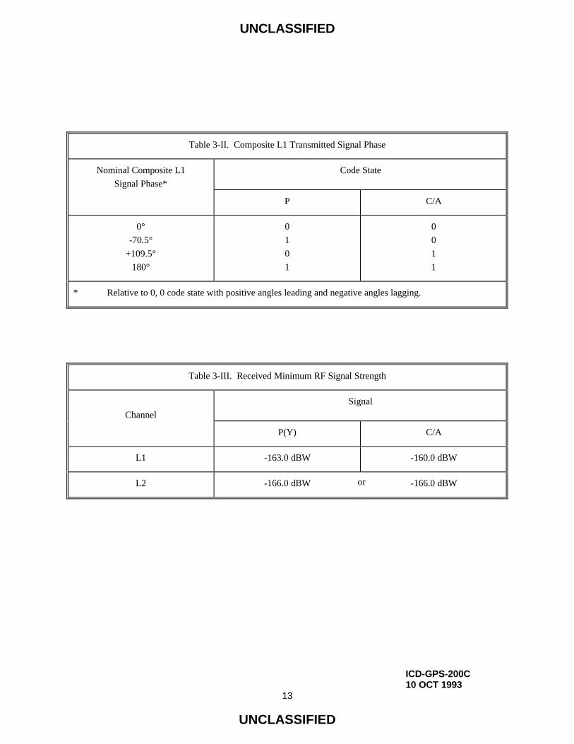
composite transmitted signal phases as a function of the binary state of the modulating signals are as shown in
Table 3-II.
3.3.1.6 User-Received Signal Levels. The SV shall provide L1 and L2 navigation in accordance with the
minimum levels specified in Table 3-III into a 3 dBi linearly polarized user receiving antenna (located near
ground) at worst normal orientation, when the SV is above a 5-degree elevation angle. Additional related data is
provided as supporting material in paragraph 6.3.1.
UNCLASSIFIED
ICD-GPS-200C10 OCT 1993
13
UNCLASSIFIED
Table 3-II. Composite L1 Transmitted Signal Phase
Nominal Composite L1
Signal Phase*
Code State
P C/A
0°
-70.5°
+109.5°
180°
0
1
0
1
0
0
1
1
* Relative to 0, 0 code state with positive angles leading and negative angles lagging.
Table 3-III. Received Minimum RF Signal Strength
Channel
Signal
P(Y) C/A
L1 -163.0 dBW -160.0 dBW
L2 -166.0 dBW -166.0 dBWor

UNCLASSIFIED
ICD-GPS-200C10 OCT 1993
14
UNCLASSIFIED
3.3.1.7 Equipment Group Delay. Equipment group delay is defined as the delay between the L-band radiated
output of a specific SV (measured at the antenna phase center) and the output of that SV's on-board frequency
source; the delay consists of a bias term and an uncertainty. The bias term is of no concern to the US since it is
included in the clock correction parameters relayed in the NAV data, and is therefore accounted for by the user
computations of system time (reference paragraph 20.3.3.3.3.1). The uncertainty (variation) of this delay as well
as the difference between the L1 vs the L2 delays are defined in the following.
3.3.1.7.1 Group Delay Uncertainty. The effective uncertainty of the group delay shall not exceed 3.0 nanoseconds
(two sigma).
3.3.1.7.2 Group Delay Differential. The group delay differential between the radiated L1 and L2 P(Y) signals is
specified as consisting of random plus bias components. The mean differential is defined as the bias component
and will be either positive or negative. For a given navigation payload redundancy configuration, the absolute
value of the mean differential delay shall not exceed 15.0 nanoseconds. The random variations about the mean
shall not exceed 3.0 nanoseconds (two sigma).
3.3.1.8 Signal Coherence. All transmitted signals for a particular SV shall be coherently derived from the same
on-board frequency standard; all digital signals shall be clocked in coincidence with the PRN transitions for the P-
signal and occur at the P-signal transition speed. On the L1 channel the data transitions of the two modulating
signals (i.e., that containing the P(Y)-code and that containing the C/A-code) shall be such that the average time
difference between the transitions does not exceed 10 nanoseconds (two sigma).

UNCLASSIFIED
IRN-200C-002ICD-GPS-200C25 SEP 1997
15
UNCLASSIFIED
3.3.1.9 Signal Polarization The transmitted signal shall be right-hand circularly polarized (RHCP). For the
angular range of ±14.3 degrees from boresight, L1 ellipticity shall be no worse than 1.2 dB for Block II/IIA and
shall be no worse than 1.8 dB for Block IIR Svs. L2 ellipticity shall be no worse than 3.2 dB for Block II/IIA SVs
and shall be no worse than 2.2 dB for Block IIR over the angular range of ±14.3 degrees from boresight.
3.3.2 PRN Code Characteristics. The characteristics of the P- and the C/A-codes are defined below in terms of
their structure and the basic method used for generating them. The characteristics of the Y-code are defined in
ICD-GPS-203 and/or ICD-GPS-224 and/or ICD-GPS-225 (see note in paragraph 2.1). Figure 3-2 depicts a
simplified block diagram of the scheme for generating the 10.23 Mbps Pi(t) and the 1.023 Mbps Gi(t) patterns
(referred to as P- and C/A-codes respectively), and for Modulo-2 summing these patterns with the NAV bit train,
D(t), which is clocked at 50 bps. The resultant composite bit trains are then used to modulate the L-band carriers.

UNCLASSIFIED
ICD-GPS-200C10 OCT 1993
16
UNCLASSIFIED
Z-COUNTER
RESETCOMMAND
GENERATOR
X1 CODEGENERATOR
CODESELECTDEVICE
X2 CODEGENERATOR
RECLOCKINGDEVICE
10.23 MHzFREQUENCY
SOURCE
GOLD CODEGENERATOR
EPOCHRESET
EPOCHDETECT
EPOCHRESET
EPOCHDETECT10
20X1 EPOCH
DATAENCODER
D(t)
Pi(t) D(t)
Pi(t)
FORMATTEDDATA
Pi(t)
X2i(t)
X1(t)Gi(t)
REMOTECOMMAND
Z-COUNT
1.023MHz
1 KHz
50 Hz
Gi(t) D(t)
Figure 3-2. Generation of Codes and Modulating Signals

UNCLASSIFIED
ICD-GPS-200C10 OCT 1993
17
UNCLASSIFIED
3.3.2.1 Code Structure. The Pi(t) pattern (P-code) is generated by the Modulo-2 summation of two PRN codes,
X1(t) and X2(t - iT), where T is the period of one P-code chip and equals (1.023 x 10⁷)-1 seconds, while i is an
integer from 1 through 37. This allows the generations of 37 unique P(t) code phases (identified in Table 3-I)
using the same basic code generator.
The linear Gi(t) pattern (C/A-code) is the Modulo-2 sum of two 1023-bit linear patterns, G1 and G2i. The latter
sequence is selectively delayed by an integer number of chips to produce 36 unique G(t) patterns (defined in Table
3-I).
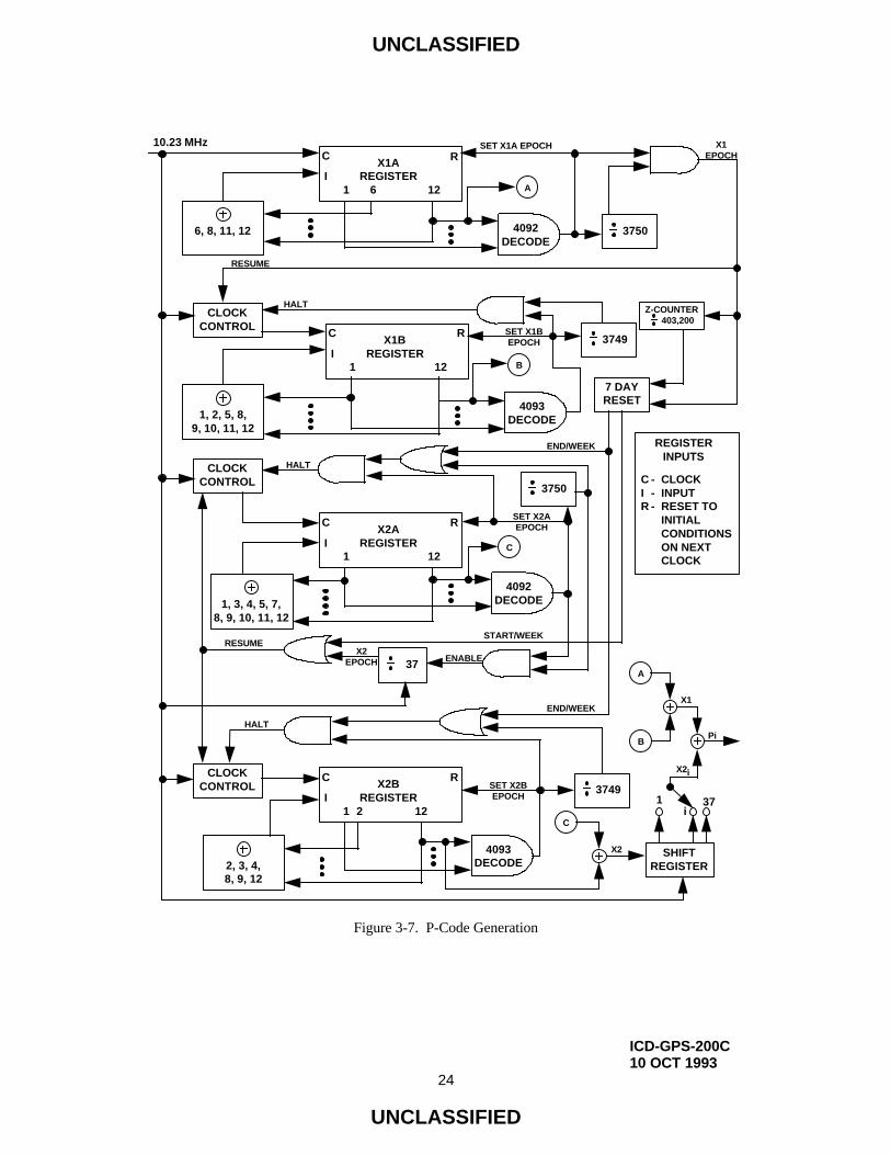
3.3.2.2 P-Code Generation. Each Pi(t) pattern is the Modulo-2 sum of two extended patterns clocked at 10.23
Mbps (X1 and X2i). X1 itself is generated by the Modulo-2 sum of the output of two 12-stage registers (X1A and
X1B) short cycled to 4092 and 4093 chips respectively. When the X1A short cycles are counted to 3750, the X1
epoch is generated. The X1 epoch occurs every 1.5 seconds after 15,345,000 chips of the X1 pattern have been
generated. The polynomials for X1A and X1B, as referenced to the shift register input, are:
X1A: 1 + X6 + X8 + X11 + X12, and
X1B: 1 + X1 + X2 + X5 + X8 + X9 + X10 + X11 + X12.
Samples of the relationship between shift register taps and the exponents of the corresponding polynomial,
referenced to the shift register input, are as shown in Figures 3-3, 3-4, 3-5 and 3-6.

UNCLASSIFIED
ICD-GPS-200C10 OCT 1993
18
UNCLASSIFIED
1
0
2
0
3
0
4
1
5
0
6
0
7
1
8
0
9
0
10
1
11
0
12
0
STAGENUMBERS
INITIALCONDITIONS
SHIFT DIRECTION
0 1 2 3 4 5 6 7 8 9 10 11 12
OUTPUT
TAPNUMBERS
POLYNOMIAL X1A:
1 + X6 + X8 + X11 + X12
Figure 3-3. X1A Shift Register Generator Configuration

UNCLASSIFIED
ICD-GPS-200C10 OCT 1993
19
UNCLASSIFIED
1
0
2
0
3
1
4
0
5
1
6
0
7
1
8
0
9
1
10
0
11
1
12
0
STAGENUMBERS
INITIALCONDITIONS
SHIFT DIRECTION
0 1 2 3 4 5 6 7 8 9 10 11 12
OUTPUT
TAPNUMBERS
POLYNOMIAL X1B:
1 + X1 + X2 + X5 + X8 + X9 + X10 + X11 + X12
Figure 3-4. X1B Shift Register Generator Configuration

UNCLASSIFIED
ICD-GPS-200C10 OCT 1993
20
UNCLASSIFIED
1
1
2
0
3
1
4
0
5
0
6
1
7
0
8
0
9
1
10
0
11
0
12
1
STAGENUMBERS
INITIALCONDITIONS
SHIFT DIRECTION
0 1 2 3 4 5 6 7 8 9 10 11 12
OUTPUT
TAPNUMBERS
POLYNOMIAL X2A:
1 + X1 + X3 + X4 + X5 + X7 + X8 + X9 + X10 + X11 + X12
Figure 3-5. X2A Shift Register Generator Configuration

UNCLASSIFIED
ICD-GPS-200C10 OCT 1993
21
UNCLASSIFIED
1
0
2
0
3
1
4
0
5
1
6
0
7
1
8
0
9
1
10
0
11
1
12
0
STAGENUMBERS
INITIALCONDITIONS
SHIFT DIRECTION
0 1 2 3 4 5 6 7 8 9 10 11 12
OUTPUT
TAPNUMBERS
POLYNOMIAL X2B:
1 + X2 + X3 + X4 + X8 + X9 + X12
Figure 3-6. X2B Shift Register Generator Configuration

UNCLASSIFIED
ICD-GPS-200C10 OCT 1993
22
UNCLASSIFIED
The state of each generator can be expressed as a code vector word which specifies the binary sequence constant of
each register as follows: (a) the vector consists of the binary state of each stage of the register, (b) the stage 12
value appears at the left followed by the values of the remaining states in order of descending stage numbers, and
(c) the shift direction is from lower to higher stage number with stage 12 providing the current output. This code
vector convention represents the present output and 11 future outputs in sequence. Using this convention, at each
X1 epoch, the X1A shift register is initialized to code vector 001001001000 and the X1B shift register is initialized
to code vector 010101010100. The first chip of the X1A sequence and the first chip of the X1B sequence occur
simultaneously in the first chip interval of any X1 period.
The natural 4095 chip cycles of these generating sequences are shortened to cause precession of the X1B sequence
with respect to the X1A sequence during subsequent cycles of the X1A sequence in the X1 period. Re-
initialization of the X1A shift register produces a 4092 chip sequence by omitting the last 3 chips (001) of the
natural 4095 chip X1A sequence. Re-initialization of the X1B shift register produces a 4093 chip sequence by
omitting the last 2 chips (01) of the natural 4095 chip X1B sequence. This results in the phase of the X1B
sequence lagging by one chip for each X1A cycle in the X1 period.
The X1 period is defined as the 3750 X1A cycles (15,345,000 chips) which is not an integer number of X1B
cycles. To accommodate this situation, the X1B shift register is held in the final state (chip 4093) of its 3749th
cycle. It remains in this state until the X1A shift register completes its 3750th cycle (343 additional chips). The
completion of the 3750th X1A cycle establishes the next X1 epoch which re-initializes both the X1A and X1B shift
registers starting a new X1 cycle.
The X2i sequences are generated by first producing an X2 sequence and then delaying it by a selected integer
number of chips, i, ranging from 1 to 37. Each of the X2i sequences is then Modulo-2 added to the X1 sequence
thereby producing up to 37 unique P(t) sequences.

UNCLASSIFIED
ICD-GPS-200C10 OCT 1993
23
UNCLASSIFIED
The X2A and X2B shift registers, used to generate X2, operate in a similar manner to the X1A and X1B shift
registers. They are short-cycled, X2A to 4092 and X2B to 4093, so that they have the same relative precession rate
as the X1 shift registers. X2A epochs are counted to include 3750 cycles and X2B is held in the last state at 3749
cycle until X2A completes its 3750th cycle. The polynomials for X2A and X2B, as referenced to the shift register
input, are:
X2A: 1 + X1 + X3 + X4 + X5 + X7 + X8 + X9 + X10 + X11 + X12, and
X2B: 1 + X2 + X3 + X4 + X8 + X9 + X12.
(The initialization vector for X2A is 100100100101 and for X2B is 010101010100).
The X2A and X2B epochs are made to precess with respect to the X1A and X1B epochs by causing the X2 period
to be 37 chips longer than the X1 period. When the X2A is in the last state of its 3750th cycle and X2B is in the
last state of its 3749th cycle, their transitions to their respective initial states are delayed by 37 chip time durations.
At the beginning of the GPS week, X1A, X1B, X2A and X2B shift registers are initialized to produce the first chip
of the week. The precession of the shift registers with respect to X1A continues until the last X1A period of the
GPS week interval. During this particular X1A period, X1B, X2A and X2B are held when reaching the last state
of their respective cycles until that X1A cycle is completed (see Table 3-IV). At this point, all four shift registers
are initialized and provide the first chip of the new week.
Figure 3-7 shows a functional P-code mechanization. Signal component timing is shown in Figure 3-8, while the
end-of-week reset timing and the final code vector states are given in Tables 3-IV and 3-V, respectively.
UNCLASSIFIED
ICD-GPS-200C10 OCT 1993
24
UNCLASSIFIED
X1AREGISTER
C
I1 6 12
R
4093DECODE
4092DECODE
4092DECODE
4093DECODE
C
CLOCKCONTROL
3750
Z-COUNTER 403,200
X1BREGISTER
C
I1 12
R
X2AREGISTER
C
I1 12
R
X2BREGISTER
C
I1 2 12
R
7 DAYRESET
SHIFTREGISTER
A
1, 2, 5, 8,9, 10, 11, 12
1, 3, 4, 5, 7,8, 9, 10, 11, 12
2, 3, 4,8, 9, 12
6, 8, 11, 12
A
CLOCKCONTROL
B
3749
3750
37
C
3749
B
CLOCKCONTROL
1i
37
10.23 MHz
C - CLOCKI - INPUTR - RESET TO
INITIALCONDITIONSON NEXTCLOCK
REGISTERINPUTS
X1EPOCH
SET X1A EPOCH
RESUME
HALT
SET X1BEPOCH
END/WEEK
HALT
START/WEEK
ENABLEX2
EPOCH
RESUME
HALT
END/WEEK
SET X2BEPOCH
X2
SET X2AEPOCH
X1
X2i
Pi
Figure 3-7. P-Code Generation

UNCLASSIFIED
ICD-GPS-200C10 OCT 1993
25
UNCLASSIFIED
0 1 2 3 0 1 2 3 0
X1 EPOCHS
X2 EPOCHS
TIME
37 Chips 74 Chips
P Epoch
0 1.5 sec 3.0 sec 4.5 sec 7 days 14 days
Figure 3-8. P-Code Signal Component Timing

UNCLASSIFIED
IRN-200C-003ICD-GPS-200C11 OCT 1999
26
UNCLASSIFIED
Table 3-IV. P-Code Reset Timing
(Last 400 µsec of 7-day period)
Code Chip
X1A-Code X1B-Code X2A-Code X2B-Code
1 345 1070 967
• • • •
• • • •
• • • •
3023 3367 4092 3989
• • • •
• • • •
• • • •
3127 3471 4092 4093
• • • •
• • • •
• • • •
3749 4093 4092 4093
• • • •
• • • •
• • • •
4092* 4093 4092 4093
* Last Chip of Week.

UNCLASSIFIED
ICD-GPS-200C10 OCT 1993
27
UNCLASSIFIED
Table 3-V. Final Code Vector States
Code Chip Number Vector State
Vector State for 1st Chip
following Epoch
X1A4091 100010010010
4092 000100100100001001001000
X1B4092 100101010101
4093 001010101010010101010100
X2A4091 111001001001
4092 110010010010100100100101
X2B4092 000101010101
4093 001010101010010101010100
NOTE: First Chip in each sequence is output bit whose leading edge occurs simultaneously with the epoch.

UNCLASSIFIED
ICD-GPS-200C10 OCT 1993
28
UNCLASSIFIED
3.3.2.3 C/A-Code Generation. Each Gi(t) sequence is a 1023-bit Gold-code which is itself the Modulo-2 sum of
two 1023-bit linear patterns, G1 and G2i. The G2i sequence is formed by effectively delaying the G2 sequence by
an integer number of chips ranging from 5 to 950. The G1 and G2 sequences are generated by 10-stage shift
registers having the following polynomials as referred to in the shift register input (see Figures 3-9 and 3-10).
G1 = X10 + X3 + 1, and
G2 = X10 + X9 + X8 + X6 + X3 + X2 + 1.
The initialization vector for the G1 and G2 sequences is 1111111111. The G1 and G2 shift registers are initialized
at the P-coder X1 epoch. The G1 and G2 registers are clocked at 1.023 MHz derived from the 10.23 MHz P-coder
clock. The initialization by the X1 epoch phases the 1.023 MHz clock to insure that the first chip of the C/A code
begins at the same time as the first chip of the P-code.
The effective delay of the G2 sequence to form the G2i sequence is accomplished by combining the output of two
stages of the G2 shift register by Modulo-2 addition (see Figure 3-11). Thirty-six of the possible combinations are
selected, one to correspond to each of the 36 different P-codes. Table 3-I contains a tabulation of the G2 shift
register taps selected and their corresponding P-code X2i and PRN signal numbers together with the first several
chips of each resultant PRN code. Timing relationships related to the C/A code are shown in Figure 3-12.

UNCLASSIFIED
ICD-GPS-200C10 OCT 1993
29
UNCLASSIFIED
1
1
2
1
3
1
4
1
5
1
6
1
7
1
8
1
9
1
10
1
STAGENUMBERS
INITIALCONDITIONS
SHIFT DIRECTION
0 1 2 3 4 5 6 7 8 9 10
OUTPUT
TAPNUMBERS
POLYNOMIAL G1:
1 + X3 + X10
INPUT
Figure 3-9. G1 Shift Register Generator Configuration

UNCLASSIFIED
ICD-GPS-200C10 OCT 1993
30
UNCLASSIFIED
1
1
2
1
3
1
4
1
5
1
6
1
7
1
8
1
9
1
10
1
STAGENUMBERS
INITIALCONDITIONS
SHIFT DIRECTION
0 1 2 3 4 5 6 7 8 9 10
OUTPUT
TAPNUMBERS
POLYNOMIAL G2:
1 + X2 + X3 +X6 + X8 + X9 + X10
INPUT
Figure 3-10. G2 Shift Register Generator Configuration

UNCLASSIFIED
ICD-GPS-200C10 OCT 1993
31
UNCLASSIFIED
10
S
C
I
C
S
I
G1REGISTER
2 3 6 8 9 10
G2REGISTER
3
10
10.23 MHz
SYNCH
X1 EPOCH
20
SYNCH
G EPOCH
1 Kbps1023
DECODE
50 bps TO DATA ENCODER
PHASE SELECTLOGIC
G2i
G1
REGISTER INPUTS
C - CLOCKI - INPUTS - SET ALL ONES
Gi
Figure 3-11. C/A-Code Generation

UNCLASSIFIED
ICD-GPS-200C10 OCT 1993
32
UNCLASSIFIED
1023 etc.
X1 Epoch @ 2/3 bps
0 1 2 18 19 0
1 msec1023 BIT Gold Code @ 1023 Kbps
1023 1023 1023 1023
Gold Code Epochs @ 1000/sec
Data @ 50 cps
20 msec
Figure 3-12. C/A-Code Timing Relationships

UNCLASSIFIED
ICD-GPS-200C10 OCT 1993
33
UNCLASSIFIED
3.3.3 Navigation Data. The content and format of the NAV data for data ID number 2 are given in Appendix II of
this document (reference paragraph 20.3.3.5.1.1). Data ID number 1 is no longer in use.
3.3.4 GPS Time and SV Z-Count. GPS time is established by the Control Segment and is referenced to a UTC (as
maintained by the U.S. Naval Observatory) zero time-point defined as midnight on the night of January 5,
1980/morning of January 6, 1980. The largest unit used in stating GPS time is one week defined as 604,800
seconds. GPS time may differ from UTC because GPS time shall be a continuous time scale, while UTC is
corrected periodically with an integer number of leap seconds. There also is an inherent but bounded drift rate
between the UTC and GPS time scales. The OCS shall control the GPS time scale to be within one microsecond of
UTC (Modulo one second).
The NAV data contains the requisite data for relating GPS time to UTC. The accuracy of this data during the
transmission interval shall be such that it shall relate GPS time (maintained by the MCS of the CS) to UTC
(USNO) within 90 nanoseconds (one sigma). This data is generated by the CS; therefore, the accuracy of this
relationship may degrade if for some reason the CS is unable to upload data to a SV. At this point, it is assumed
that alternate sources of UTC are no longer available, and the relative accuracy of the GPS/UTC relationship will
be sufficient for users. Range error components (e.g. SV clock and position) contribute to the GPS time transfer
error, and under normal operating circumstances (two frequency time transfers from SV(s) whose navigation
message indicates a URA of eight meters or less), this corresponds to a 97 nanosecond (one sigma) apparent
uncertainty at the SV. Propagation delay errors and receiver equipment biases unique to the user add to this time
transfer uncertainty.

UNCLASSIFIED
ICD-GPS-200C10 OCT 1993
34
UNCLASSIFIED
In each SV the X1 epochs of the P-code offer a convenient unit for precisely counting and communicating time.
Time stated in this manner is referred to as Z-count, which is given as a 29-bit binary number consisting of two
parts as follows:
a. The binary number represented by the 19 least significant bits of the Z-count is referred to as the time of
week (TOW) count and is defined as being equal to the number of X1 epochs that have occurred since the
transition from the previous week. The count is short-cycled such that the range of the TOW-count is
from 0 to 403,199 X1 epochs (equaling one week) and is reset to zero at the end of each week. The TOW-
count's zero state is defined as that X1 epoch which is coincident with the start of the present week. This
epoch occurs at (approximately) midnight Saturday night-Sunday morning, where midnight is defined as
0000 hours on the Universal Coordinated Time (UTC) scale which is nominally referenced to the
Greenwich Meridian. Over the years the occurrence of the "zero state epoch" may differ by a few seconds
from 0000 hours on the UTC scale since UTC is periodically corrected with leap seconds while the TOW-
count is continuous without such correction. To aid rapid ground lock-on to the P-code signal, a truncated
version of the TOW-count, consisting of its 17 most significant bits, is contained in the hand-over word
(HOW) of the L-Band downlink data stream; the relationship between the actual TOW-count and its
truncated HOW version is illustrated by Figure 3-13.
b. The ten most significant bits of the Z-count are a binary representation of the sequential number assigned
to the present GPS week (Modulo 1024). The range of this count is from 0 to 1023 with its zero state
being defined as that week which starts with the X1 epoch occurring at approximately midnight on the
night of January 5, 1980/morning of January 6, 1980. At the expiration of GPS week number 1023, the
GPS week number will rollover to zero(0). Users must account for the previous 1024 weeks.

UNCLASSIFIED
ICD-GPS-200C10 OCT 1993
35
UNCLASSIFIED
403,192 403,196 403,199
P(Y)-CODE EPOCH(END/START OF WEEK)
10 2 3 4 5 6 7 8
100,799 10 2 3
X1 EPOCHS 1.5 sec
DECIMAL EQUIVALENTSOF ACTUAL TOW COUNTS
SUBFRAME EPOCHS
DECIMAL EQUIVALENTS OF HOW-MESSAGE TOW COUNTS
NOTES:
1. TO AID IN RAPID GROUND LOCK-ON THE HAND-OVER WORD (HOW ) OF EACHSUBFRAME CONTAINS A TRUNCATED TIME-OF-WEEK (TOW) COUNT
2. THE HOW IS THE SECOND WORD IN EACH SUBFRAME (REFERENCEPARAGRAPH 20.3.3.2).
3. THE HOW-MESSAGE TOW COUNT CONSISTS OF THE 17 MSBs OF THEACTUAL TOW COUNT AT THE START OF THE NEXT SUBFRAME.
4. TO CONVERT FROM THE HOW-MESSAGE TOW COUNT TO THE ACTUAL TOWCOUNT AT THE START OF THE NEXT SUBFRAME, MULTIPLY BY FOUR.
5. THE FIRST SUBFRAME STARTS SYNCHRONOUSLY WITH THE END/START OFWEEK EPOCH.
6 sec
Figure 3-13. Time Line Relationship of HOW Message

UNCLASSIFIED
ICD-GPS-200C10 OCT 1993
36
UNCLASSIFIED
(This page intentionally left blank.)

UNCLASSIFIED
ICD-GPS-200C10 OCT 1993
37
UNCLASSIFIED
4. NOT APPLICABLE

UNCLASSIFIED
ICD-GPS-200C10 OCT 1993
38
UNCLASSIFIED
(This page intentionally left blank.)

UNCLASSIFIED
ICD-GPS-200C10 OCT 1993
39
UNCLASSIFIED
5. NOT APPLICABLE

UNCLASSIFIED
ICD-GPS-200C10 OCT 1993
40
UNCLASSIFIED
(This page intentionally left blank.)

UNCLASSIFIED
IRN-200C-003ICD-GPS-200C11 OCT 1999
41
UNCLASSIFIED
6. NOTES
6.1 Acronyms
AI - Availability Indicator
AODO - Age of Data Offset
A-S - Anti-Spoofing
Autonav - Autonomous Navigation
BPSK - Bi-Phase Shift Key
CS - Control Segment
DN - Day Number
EAROM - Electrically Alterable Read-Only Memory
ECEF - Earth-Centered, Earth-Fixed
ECI - Earth-Centered, Inertial
ERD - Estimated Range Deviation
GPS - Global Positioning System
HOW - Hand-Over Word
ICC - Interface Control Contractor
ICD - Interface Control Document
ID - Identification
IODC - Issue of Data, Clock
IODE - Issue of Data, Ephemeris
LSB - Least Significant Bit
LSF - Leap Seconds Future
MCS - Master Control Station
MSB - Most Significant Bit
NAV - Navigation
NDUS - Nudet Detection User Segment
NMCT - Navigation Message Correction Table
NSC - Non-Standard C/A-Code
NSY - Non-Standard Y-code
OBCP - On-Board Computer Program
OCS - Operational Control Segment
PRN - Pseudo-Random Noise
RF - Radio Frequency

UNCLASSIFIED
IRN-200C-002ICD-GPS-200C25 SEP 1997
42
UNCLASSIFIED
RMS - Root Mean Square
SA - Selective Availability
SEP - Spherical Error Probable
SS - Space Segment
SV - Space Vehicle
SVN - Space Vehicle Number
TBD - To Be Determined
TBS - To Be Supplied
TLM - Telemetry
TOW - Time Of Week
UE - User Equipment
URA - User Range Accuracy
URE - User Range Error
US - User Segment
USNO - U.S. Naval Observatory
UTC - Universal Coordinated Time
WGS 84 - World Geodetic System 1984
WN - Week Number

UNCLASSIFIED
ICD-GPS-200C10 OCT 1993
43
UNCLASSIFIED
6.2 Definitions
6.2.1 User Range Accuracy. User range accuracy (URA) is a statistical indicator of the ranging accuracies
obtainable with a specific SV. URA is a one-sigma estimate of the user range errors in the navigation data for the
transmitting satellite. It includes all errors for which the Space and Control Segments are responsible. It does not
include any errors introduced in the user set or the transmission media. While the URA may vary over a given
subframe fit interval, the URA index (N) reported in the NAV message corresponds to the maximum value of URA
anticipated over the fit interval.
6.2.2 SV Block Definitions. The following block definitions are given to facilitate discussion regarding the
capability of the various blocks of GPS satellites to support the SV-to-US interface.
6.2.2.1 Developmental SVs. The original concept validation satellites developed by Rockwell International and
designated as satellite vehicle numbers (SVNs) 1-11 are termed "Block I" SVs throughout this document. These
SVs were designed to provide 3-4 days of positioning service without contact from the CS. These SVs transmit a
configuration code of 000 (reference paragraph 20.3.3.5.1.6).
6.2.2.2 Operational SVs. The operational satellites are designated Block II, Block IIA and Block IIR SVs.
Characteristics of these SVs are provided below. Modes of operation for these SVs and accuracy of positioning
services provided are described in paragraphs 6.3.2 through 6.3.4. These SVs all transmit a configuration code of
001 (reference 20.3.3.5.1.6). The navigation signal provides no direct indication of the type of the transmitting
SV.

UNCLASSIFIED
ICD-GPS-200C10 OCT 1993
44
UNCLASSIFIED
6.2.2.2.1 Block II SVs. The first block of full scale operational SVs developed by Rockwell International are
designated as SVNs 13-21 and are termed "Block II" SVs. These SVs were designed to provide 14 days of
positioning service without contact from the CS.
6.2.2.2.2 Block IIA SVs. The second block of full scale operational SVs developed by Rockwell International are
designated as SVNs 22-40 and are termed "Block IIA" SVs. These SVs were designed to provide 180 days of
positioning service without contact from the CS.
6.2.2.2.3 Block IIR SVs. The block of operational replenishment SVs developed by Martin Marietta are
designated as SVNs 41-66 and are termed "Block IIR" SVs. These SVs will provide at least 14 days of positioning
service without contact from the CS when the SVs are operating in the Block IIA mode and will provide a
minimum of 180 days of positioning service without contact from the CS when operating in autonomous
navigation (Autonav) mode.
6.2.3 Operational Interval Definitions. The following three operational intervals have been defined. These labels
will be used to refer to differences in the interface definition as time progresses from SV acceptance of the last
navigation data upload.
6.2.3.1 Normal Operations. The SV is undergoing normal operations whenever the fit interval flag (reference
paragraph 20.3.3.4.3.1) is zero.
6.2.3.2 Short-term Extended Operations. The SV is undergoing short-term extended operations whenever the fit
interval flag is one and the IODE (reference paragraph 20.3.4.4) is less than 240.

UNCLASSIFIED
ICD-GPS-200C10 OCT 1993
45
UNCLASSIFIED
6.2.3.3 Long-term Extended Operations. The SV is undergoing long-term extended operations whenever the fit
interval flag is one and the IODE is in the range 240-255.
Note: the DoD Navigation User Segment and Time Transfer User have no requirement to operate, and may not
operate properly, whenever any SV is operating in long-term extended operations.
6.3 Supporting Material
6.3.1 Received Signals. The guaranteed minimum user-received signal levels are defined in paragraph 3.3.1.6.
As additional supporting material, Figure 6-1 illustrates the minimum power of the near-ground user-received L1
and L2 signals as a function of SV elevation angle using the following assumptions: (a) the signal is measured at
the output of a 3 dBi linearly polarized receiving antenna; (b) the SV is above a 5 degree elevation angle; (c) the
received signal levels are observed within the in-band allocation defined in paragraph 3.3.1.1; (d) the atmospheric
path loss is 2.0 dB; and (e) the SV attitude error is 0.5 degrees (towards reducing signal level). The actual SV
attitude error will not exceed ±0.5 degrees after the SV has stabilized to its final orbital state.

UNCLASSIFIED
ICD-GPS-200C10 OCT 1993
46
UNCLASSIFIED
-157
-160
-163
-166
0o 5o 20o 40o 60o 80o 100o90o
USER ELEVATION ANGLE (DEG)
RE
CE
IVE
D P
OW
ER
AT
3dB
i LIN
EA
RLY
PO
LAR
IZE
D A
NT
EN
NA
(dB
w) C/A - L1
P - L1
P - L2 or
C/A - L2
Figure 6-1. User Received Minimum Signal Levels

UNCLASSIFIED
ICD-GPS-200C10 OCT 1993
47
UNCLASSIFIED
Higher received signals levels can be caused by such factors as SV attitude errors, mechanical antenna alignment
errors, transmitter power output variations due to temperature variations, voltage variations and power amplifier
variations, and due to a variability in link atmospheric path loss. The maximum received signal levels as a result
of these factors is not expected to exceed -155.5 dBw and -153.0 dBw, respectively, for the P(Y) and C/A
components of the L1 channel, nor -158.0 dBw for either signal on the L2 channel. This estimate assumes that the
receiving antenna characteristics are as described above, the atmospheric loss is 0.6 dB and the SV attitude error is
0.5° (towards increased signal level).
6.3.2 Extended Navigation Mode (Block II/IIA). The Block II and IIA SVs are capable of being uploaded by the
CS with 182 days of navigation data to support a 180 day positioning service. Due to memory retention
limitations, the Block II SVs may not transmit correct data for the entire 180 days but are guaranteed to transmit
correct data for at least 14 days to support short-term extended operations. Under normal conditions the CS will
provide daily uploads to each SV, which will allow the SV to maintain normal operations as defined in paragraph
6.2.3.1 and described within this ICD. During normal operations, the SVs will have a user range error that is at or
below a level required to support a positioning accuracy of 16 meters spherical error probable (SEP). In addition,
the almanac data, UTC parameters and ionospheric data will be maintained current to meet the accuracy specified
in this ICD.
If the CS is unable to upload the SVs (the CS is unavailable or the SV is unable to accept and process the upload),
each SV will individually transition to short-term extended operations and eventually to long-term extended
operations (based on time from each SV's last upload) as defined in paragraphs 6.2.3.2 and 6.2.3.3, and as further
described throughout this ICD. As time from upload continues through these three operational intervals, the user
range error of the SV will increase, causing a positioning service accuracy degradation. The rate of accuracy
degradation is slow over the short-term extended operations interval, such that at the end of this interval
(approximately 14 days after upload) the US will be able to achieve a positioning accuracy of 425 meters SEP. The
rate of accuracy degradation increases in the long-term extended interval, such that by the 180th day after the last
upload, the positioning errors will have grown to 10 kilometers SEP. During these intervals the URA will continue
to provide the proper estimate of the user range errors.

UNCLASSIFIED
ICD-GPS-200C10 OCT 1993
48
UNCLASSIFIED
During short-term and long-term extended operations (approximately day 2 through day 182 after an upload), the
almanac data, UTC parameters and ionospheric data will not be maintained current and will degrade in accuracy
from the time of last upload.
6.3.3 Block IIA Mode (Block IIR). The Block IIR SVs, when operating in the Block IIA mode, will perform
similarly to the Block IIA SVs and will provide at least 14 days of positioning service (through short-term
extended operations) without contact from the CS.
6.3.4 Autonomous Navigation Mode. The Block IIR SV, in conjunction with a sufficient number of other Block
IIR SVs, operates in an Autonav mode when commanded by the CS. Each Block IIR SV in the constellation
determines its own ephemeris and clock correction parameters via SV-to-SV ranging, communication of data, and
on-board data processing which updates data uploaded by the CS. In the Autonav mode the Block IIR SV will
maintain normal operations as defined in paragraph 6.2.3.1 and as further described within this ICD, and will have
a user range error that is at or below a level required to support 16 meter SEP accuracy. If the CS is unable to
upload the SVs, the Block IIR SVs will maintain normal operations for period of at least 180 days after the last
upload.
In the Autonav mode, the almanac data, UTC parameters and ionospheric data are still calculated and maintained
current by the CS and uploaded to the SV as required. If the CS is unable to upload the SVs, the almanac data,
UTC parameters and ionospheric data will not be maintained current and will degrade in accuracy from the time of
the last upload.

UNCLASSIFIED
ICD-GPS-200C10 OCT 1993
49
UNCLASSIFIED
10. APPENDIX I. LETTERS OF EXCEPTION
10.1 Scope. As indicated in paragraph 1.3, initial signature approval of this document, as well as approval of
subsequent changes to the document, can be contingent upon a "letter of exception". This appendix depicts such
"letters of exception" when utilized by any signatory of this document in the initial approval cycle and/or in the
change approval process. The ICC will omit such letters of exception from subsequent revisions of this document
based on written authorization by the respective signatory (without processing a proposed interface revision notice
(PIRN) for approval). When some (but not all) of the exceptions taken by a signatory are resolved, the signatory
shall provide the ICC with an updated letter of exception for inclusion in the next ICD revision (without processing
a PIRN for approval).
10.2 Applicable Documents. The documents listed in Section 2.0 shall be applicable to this appendix.
10.3 Letters of Exception. If signature approval of this document -- as affixed to the cover page -- is marked by an
asterisk, it indicates that the approval is contingent upon the exceptions taken by that signatory in a letter of
exception. Any letter of exception which is in force for the revision of the ICD is depicted in Figure 10-1.
Signatories for whom no letter of exception is shown have approved this version of the document without
exception.

UNCLASSIFIED
ICD-GPS-200C10 OCT 1993
50
UNCLASSIFIED
(This page intentionally left blank.)

UNCLASSIFIED
IRN-200C-002ICD-GPS-200C25 SEP 1997
51
UNCLASSIFIED
Space Systems DivisionRockwell International Corporation
2600 Westminster BoulevardP.O. Box 3644
Seal Beach, California 90740-7644RockwellInternational
In reply refer to 93MA3728
Date: September 22, 1993
To: The ARINC Companies11770 E. Warner Ave., Suite 210Fountain Valley, CA 92708
Subject: Rockwell International Letter of Exception toICD GPS-200 PIRN-200A-006NC, dated November
21,1986.
Attention: Thomas R. Denigan
Reference: ARINC Companies FAX dated September 20, 1993,T. R. Denigan to D. L. Butler, same subject.
It is Rockwell’s position that the statement requested in the subjectletter of exception be incorporated, as written, in the next revision toICD-200. The ‘B’ revision of ICD-200 incorporated only the lastportion of the requested change “....the initialization vector for X2A is100100100101 and for X2B is 010101010100.” It is felt that the firstportion of the sentence, “Using the same convention identified for X1Aand X1B,...” will aid the reader of the ICD in understanding thederivation of the X2A and X2B terms.
ROCKWELL INTERNATIONALSpace Systems Division
Signature on file Signature on fileW. L Young, Manager F. E. Cooper, ChiefEngineerContracts & Proposals GPS Program
cc: D. L. ButlerW. F. Fratzke
Figure 10-1. Letter of Exception (sheet 1 of 15)

UNCLASSIFIED
IRN-200C-002ICD-GPS-200C25 SEP 1997
52
UNCLASSIFIED
Collins Avionics & Communications DivisionRockwell International Corporation
350 Collins Road NECedar Rapids, IA 52498
(319) 395-1000RockwellInternational
September 23, 1993
ARINC Research Corporation11770 Warner Avenue, Suite 210Fountain Valley, CA 92708
Attention: Mr. Tom Denigan
Subject: Review of ICD-GPS-200B Outstanding Letters of Exception in Preparation of ICD-GPS-200C
Dear Mr. Denigan:
A review of Rockwell International’s Collins Avionics & CommunicationsDivision, outstanding Letters of Exception as listed in IRN-200B-007 toICD-GPS-200B shows 2 Letters of Exception that have been satisfied or areno longer pertinent:
sheet 46, (letter dated March 31, 1987)sheet 53 & 54, (letter dated September 10, 1986)
The following letters as listed in IRN-200B-007 to ICD-GPS-200B are stillpertinent and are to be included in any revised ICD-GPS-200 releases:
sheet 54a, 54c (letter dated March 27, 1991)sheet 56g (letter dated September 23, 1992)
Sincerely,
Signature on fileC.S, OlsonProgram Manager
Figure 10-1. Letter of Exception (sheet 2 of 15)

UNCLASSIFIED
IRN-200C-002ICD-GPS-200C25 SEP 1997
53
UNCLASSIFIED
Collins Avionics & Communications DivisionRockwell International Corporation
350 Collins Road NECedar Rapids, IA 52498
(319) 395-1000RockwellInternational
2458b/0048bMarch 27, 1991
ARINC Research Corporation4410 East Fountain Blvd., Suite 100Colorado Springs, CO 80916
Attention: Ms. Cheryl Abendschan
Subject: Rockwell CACD Letter of Exception against PIRN-200B-001B (ascorrected by ARINC memo on typos and oversights, 19 MAR 91)
The subject PIRN-200B-001B documents the extended navigation capabilities inherent in theSpace Segment/User Segment interface as a result of the incorporation of mission packagesoftware release OR5.10 into the Control Segment. CACD’s approval of this PIRN, whichindicates concurrence that the PIRN accurately reflects the as-built Control and SpaceSegments in the area of extended navigation, is given with exception.
CACD takes exception because:
1. The extended navigation capabilities documented by the PIRN are not a requirement ofthe GPS Phase III User Equipment (UE) contract F04701-85-C-0038, the GPS UEPhase IV contract F04701-90-C-0092, or the GPS MAGR Contract F04701-91-C-0003. Therefore, the GPS User Equipment, which has been and will be developed underthese contracts, do no operate in compliance with extended navigation.
2. While we may technically comment on the impact to the UE as a result of OR5.10
implementation, we cannot (as PIRN approval might otherwise indicate) verify thatOR5.10 implements the extended navigation requirements identified in the PIRN.
In summary, “Long Term Extended” operations from 15 to 180 days following an uploadfrom the Control Segment are not supported by the Phase III GPS UE. Attachment 1contains the detailed comments on the PIRN items to which CACD takes exception.
Sincerely,
Signature on fileJ. L. ArnoldGPS Programs Manager
Enclosurecc: Lt. Jim Dagley Capt. Greg Laushine
Figure 10-1. Letter of Exception (sheet 3 of 15)

UNCLASSIFIED
IRN-200C-002ICD-GPS-200C25 SEP 1997
54
UNCLASSIFIED
ATTACHMENT 1
Rockwell CACD Exceptions to PIRN-200B-001B
PIRN ITEM Rockwell CACD Comment
17, 18 These PIRN items document the change in the definition of the WeekNumber in subframe 1, word 3 due to the implementation of long termextended ephemeris curve fits which cross GPS week boundaries. Thenew definition states that the week number is the ten most significant bitsof the Z-count and will represent the GPS week of the start of the data settransmission interval. Previously, the week number always representedthe current GPS week of transmission. CACD takes exception to thisredefinition because:
1. The PIRN introduces an inconsistency with the definition of Z-countgiven in paragraph 3.3.4, page 33 which states that “the ten mostsignificant bits of the Z-count are a binary representation of the sequentialnumber assigned to the present GPS week (Module 1024).”
2. Since the GPS week being transmitted by the Space Segment couldvary from SV to SV (depending upon time of upload) and since thetransmitted GPS week could be different from the current GPS week byone week starting on day 29 after an upload, the GPS UE could navigateusing the wrong GPS week. Use of the wrong GPS week could causenavigation interruptions and could result in the incorrect time-tagging ofthe satellite data. The user could therefore be provided with navigationdata which is marked valid when, in fact, it is not valid. This is anunacceptable situation.
22,29,31, 57a, 57b,58, 60 These PIRN items document the change in the definition of the ephemerisfit interval flag for a value equal to 1 and its corresponding relationship tothe IODC/IODE during extended operations. The GPS UE supports onlya fit interval of 6 hours when the fit interval flag equals 1. The newlydefined ephemeris fit intervals of 8, 14, 26, 50, 74, 98, 122, and 146hours for Long Term Extended Operations are not supported and the UEwill compute 6 hour curve fits whenever these are in effect.
Figure 10-1. Letters of Exception (sheet 4 of 15)

UNCLASSIFIED
IRN-200C-002ICD-GPS-200C25 SEP 1997
55
UNCLASSIFIED
ATTACHMENT 1 (cont.)
Rockwell CACD Exceptions to PIRN-200B-001B
PIRN ITEM Rockwell CACD Comment
39, 40, 50, 54 These PIRN items describe the almanac data sets and how the almanacURE grows throughout extended operations. The GPS UE requirementsfor almanac-based direct P-code TTFF (time to first fix) are onlyapplicable to Normal Operations in which the almanac parameters havebeen updated within the last six days. Extended operations mayjeopardize missions of those users who require efficient almanac-baseddirect P-code TTFFs.
43 This PIRN item documents the fact that the health summary in subframe5, page 25 is only updated at the time of almanac upload. Duringextended operations the health summary may become outdated due to thelength of time since the last upload.
If the health summary becomes outdated and does not accurately reflectthe status of the GPS constellation, the TTFF for the GPS UE may bedelayed. This is due to the time wasted on the possible acquisition ofunhealthy SVs which were marked “healthy” by the health summary. Also, attempts to acquire healthy SVs which are marked unhealthy willnot be made. As a result, extended operations may jeopardize missions ofthose users who require efficient TTFF.
45,46 These PIRN items document the changes for the UTC parameter data setsduring extended operations. The GPS UE uses the UTC parameters toprovide the user with precise time. Exception is taken because:
1. CACD is not confident that the accuracy of the UTC parameters can bemaintained throughout extended operations. This accuracy is specified as90 ns (one sigma) on ICD-GPS-200B page 32. As a result, extendedoperations may jeopardize missions of those users who require preciseUTC.
2. Since the GPS UE does not account for the degraded accuracy of theUTC parameters as a function of time during extended operations, theuser may be provided with an incorrect estimate of his time accuracywhich again may jeopardize his mission. CACD believes the UTCparameters’ accuracy, as a function of time, should be specified in someGPS system specification.
Figure 10-1. Letters of Exception (sheet 5 of 15)

UNCLASSIFIED
IRN-200C-002ICD-GPS-200C25 SEP 1997
56
UNCLASSIFIED
Collins Avionics & Communications DivisionRockwell International Corporation
350 Collins Road NECedar Rapids, IA 52498
(319) 395-1000RockwellInternational
September 23, 1992
ARINC Research Corporation11770 Warner Avenue, Suite 210Fountain Valley, CA 92708
Attention: Mr. Peter Fyfe
Subject: PIRN-200B-009A Rockwell CACD Letter of Exception
Dear Mr. Fyfe:
The subject PIRN-200B-009A which documents the changes to the Space Segment/UserSegment interface for the Block IIR SVs is hereby approved by Rockwell CACD with thefollowing exception:
The PIRN states that UTC parameters (PIRN items 4, 20), ionospheric modelparameters (PIRN items 21, 27a), and almanac data (PIRN items 22a, 22b) willdegrade when the Block IIR SVs do not receive an upload from the ControlSegment. Since the IIR SVs indicate “normal operations” (curve fit interval flag of 4hours) at all times, dome user segment requirements cannot be met during “normaloperations” in the absence of Control Segment uploads. These affectedrequirements are precise UTC time transfer and almanac-based direct P-code time tofirst fix.
The affected User Equipment (UE) is that designed and developed by Rockwell CACD underthe GPS UE Phase III Contract F04701-85-C-0038, GPS UE Phase IV Contract F04701-90-C-0092, and GPS MAGR Contract F04701-91-C-0003.
Sincerely,
Signature on fileC. S. OlsonProgram Manager
CSS/jk
Figure 10-1. Letters of Exception (sheet 6 of 15)

UNCLASSIFIED
IRN-200C-002ICD-GPS-200C25 SEP 1997
57
UNCLASSIFIED
Collins Avionics & Communications DivisionRockwell International Corporation
350 Collins Road NECedar Rapids, IA 52498
(319) 395-1000
RockwellInternational
June 12, 1995
ARINC Research Corporation2250 East Imperial Highway, Suite 450El Segundo, CA 90245-3509
Attention: Mr. Thomas Denigan
Subject: PIRN-200C-001 Rockwell CACD Letter of Exception
Enclosure: Approval sheet for PIRN-300C-001
References: ARINC Research Corporation letter dated January 16, 1995; Subject: PIRN-200C-001 to ICD-GPS-200C
The subject PIRN-200C-001 is approved by Rockwell CACD with the followingexception:
The effect of Item 2, “Change Section 20.3.3.5.2.2, page 121” of this PIRNis that computed almanac age in Rockwell CACD government UserEquipment (UE) will be approximately 14 hours older than actual almanac age. Since almanac age computation is for display/output purposes only there is no impact to receiver operation or navigation solution accuracy. CACD computes an almanac time-of-transmission that is nominally the multiple of 212 seconds truncated from 3.5 days prior to the almanac reference time, toa. Item 2 of subject PIRN-200C-001documents the change of toa from being nominally the multiple of 212
seconds truncated from 3.5 days (84 hours) after the first valid transmission time for an almanac set to being nominally the multiple of 212 seconds truncated from 70 hours after the first valid transmission timefor an almanac set. Therefore, Rockwell CACD government UE willcompute and output an incorrect almanac age by approximately 14 hours.
Figure 10-1. Letters of Exception (sheet 7 of 15)

UNCLASSIFIED
IRN-200C-002ICD-GPS-200C25 SEP 1997
58
UNCLASSIFIED
The second sentence of paragraph 20.3.3.5.2.2, “The almanac is updated oftenenough to ensure that GPS time, t, shall differ from toa by less than 3.5 days during the transmission period”, must not change. This is to ensure the properresolution of the GPS week number associated with the almanac.
Technical questions concerning this matter should be referenced to Lawrence Burnsat (319)395-2616.
Sincerely,
Signature on fileCraig OlsonGPS Program Manager
Figure 10-1. Letters of Exception (sheet 8 of 15)

UNCLASSIFIED
IRN-200C-002ICD-GPS-200C25 SEP 1997
59
UNCLASSIFIED
International Business Machines Corporation 800 N. Frederick AvenueGaithersburg, MD 20879
RD001001935October 1, 1993
Mr. Tom DeniganARINC Research Corporation11770 Warner Avenue, suite 210Fountain Valley, CA 92780
Subject: IBM “Letter of Exception” against ICD-GPS-200B asModified by IRN-200B-001B
Reference: 1. ICD-GPS-200B, dated November 30, 19872. IRN-200B-001B, dated April 15,, 19913. IRN-200B-002, dated July 26, 19914. IRN-200B-003, dated December 2, 19915. IRN-200B-004, dated December 5, 19916. IRN-200B-005, dated December 16, 19917. IRN-200B-006, dated December 9, 19928. IRN-200B-007, dated July 19, 19939. IBM letter 020689-2, dated February 6, 198910. Contract F04701-90-C-0009
Dear Mr. Denigan:
With the release of the referenced IRN-200B-001B through -007, this letterrepresents the current IBM letter of exception against ICD-GPS-200B,replacing Reference 9.
The IBM contract does not support the following:
Block I end of data transmission (Paragraph 20.3.2)
The option of repeated almanacs for 12 or fewer SVs (Paragraphs20.3.3.5.1.2, 20.3.3.5.1.3)
The use of pages 2, 3, 4, 5, 7, 8, 9, and 10 of subframe 4 for purpose otherthan almanac data for SVs 25 through 32 (Paragraphs 20.3.3.5.1, 20.3.3.5.1.1, 20.3.3.5.1.3, Table 20-V)
Figure 10-1. Letters of Exception (sheet 9 of 15)

UNCLASSIFIED
IRN-200C-002ICD-GPS-200C25 SEP 1997
60
UNCLASSIFIED
-2-
Mr. Tom Denigan RD001001935October 1, 1993
Questions and coordination related to the technical content of ICD-GPS-200 should be addressed to Ming Kang Chien at 301/240-6449.
Very truly yours,
Signature on fileMagdalena V. ClyneContract Administrator
cc: Capt. B. Schrimsher, SMC/CZGD 1 Lt. R. Layton, SMC/CZET 1
Figure 10-1. Letters of Exception (sheet 10 of 15)
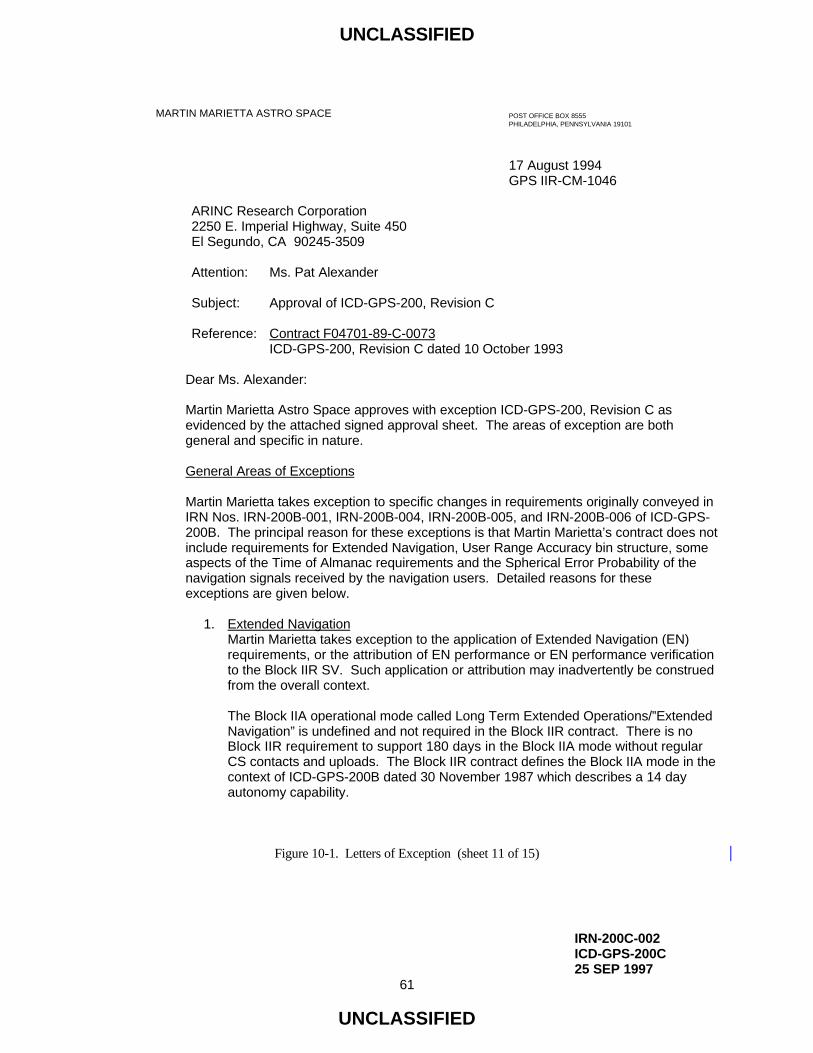
UNCLASSIFIED
IRN-200C-002ICD-GPS-200C25 SEP 1997
61
UNCLASSIFIED
MARTIN MARIETTA ASTRO SPACE POST OFFICE BOX 8555PHILADELPHIA, PENNSYLVANIA 19101
17 August 1994GPS IIR-CM-1046
ARINC Research Corporation2250 E. Imperial Highway, Suite 450El Segundo, CA 90245-3509
Attention: Ms. Pat Alexander
Subject: Approval of ICD-GPS-200, Revision C
Reference: Contract F04701-89-C-0073ICD-GPS-200, Revision C dated 10 October 1993
Dear Ms. Alexander:
Martin Marietta Astro Space approves with exception ICD-GPS-200, Revision C asevidenced by the attached signed approval sheet. The areas of exception are bothgeneral and specific in nature.
General Areas of Exceptions
Martin Marietta takes exception to specific changes in requirements originally conveyed inIRN Nos. IRN-200B-001, IRN-200B-004, IRN-200B-005, and IRN-200B-006 of ICD-GPS-200B. The principal reason for these exceptions is that Martin Marietta’s contract does notinclude requirements for Extended Navigation, User Range Accuracy bin structure, someaspects of the Time of Almanac requirements and the Spherical Error Probability of thenavigation signals received by the navigation users. Detailed reasons for these exceptions are given below.
1. Extended NavigationMartin Marietta takes exception to the application of Extended Navigation (EN)requirements, or the attribution of EN performance or EN performance verificationto the Block IIR SV. Such application or attribution may inadvertently be construedfrom the overall context.
The Block IIA operational mode called Long Term Extended Operations/”ExtendedNavigation” is undefined and not required in the Block IIR contract. There is noBlock IIR requirement to support 180 days in the Block IIA mode without regular CS contacts and uploads. The Block IIR contract defines the Block IIA mode in thecontext of ICD-GPS-200B dated 30 November 1987 which describes a 14 dayautonomy capability.
Figure 10-1. Letters of Exception (sheet 11 of 15)

UNCLASSIFIED
IRN-200C-002ICD-GPS-200C25 SEP 1997
62
UNCLASSIFIED
17 August 1994GPS IIR-CM-1046Page 2
The Block IIR design supports 180 day autonomy in the context of the AutonomousNavigation mode and 14 day autonomy in the Block IIA mode. It may be possible toconstruct upload databases that will allow operation beyond 14 days with the currentdesign, but this is not a current requirement. The Block IIR Space Vehicle does notsupport such an upload design, performance description, and performance verification.
Section 20.3.2, sentence 2 states “Block IIR SVs are designed to have sufficientmemory to store 182 days of upload NAV data in the Block IIA mode ...” MartinMarietta takes exception to a “182 day” NAV data storage requirement in the Block IIA mode. The Block IIR design and validation plan is required to provideperformance and memory margin computed on 14 day storage in the IIA mode asdefined in Section 20.3.4.4 and 20.3.4.5 of the ICD-GPS-200B dated 30 November1987.
Sections 20.3.4.4 and 20.3.4.5 with new Tables 20-XII and 20-XIII, define different“days spanned”, “fit intervals”, and “transmission intervals” compared to the 30November 1987 ICD-GPS-200B. These changes are generated by some of theExtended Navigation upload characteristics for the Block IIA SV which supports “182days” of data. Martin Marietta takes exception to evaluation and validation of theBlock IIR design performance under these modified sections and tables.
2. URA Bin StructureMartin Marietta takes exception to items relating to URA index to ranges of URA inmeters appears to require the Block IIR SV in the Autonomous Navigation (AN) modeto transition from on index to the next at exactly the values of URA indicated. Thisspecification of URA bins is not a defined requirement for Block IIR. The Block IIR ANdesign is based on the equations and the ‘no better than’ descriptions present in ICD-GPS-200B, in accordance with the Block IIR implementation.
When in the AN mode, the Martin Marietta design estimates URA on board the SVand converts the result to the index in the NAV user message by rearranging theequations and solving for the index. As a result, our design approximates, but doesnot exactly match, the description when Block IIR is in the AN mode.
When Block IIR is in the IIA mode, the Martin Marietta design does match the URA bindescription exactly because we broadcast the index uploaded from the CS and the CS estimates URA.
3. Spherical Error Probable (SEP)Martin Marietta takes exception to the URE statement in 6.3.4 since it implies MartinMarietta responsibility to relate Block IIR URE to 16 meters SEP.
Figure 10-1. Letters of Exception (sheet 12 of 15)

UNCLASSIFIED
IRN-200C-002ICD-GPS-200C25 SEP 1997
63
UNCLASSIFIED
17 August 1994GPS IIR-CM-1046Page 3
IRN-200B-006 added section 6.3.4 on “Autonomous Navigation Mode.” The thirdsentence states that the Block IIR SV in the Autonav mode “... will have a user rangeerror that is at or below a level required to support 16 meter SEP accuracy.” TheBlock IIR SV constellation, when authorized to operate in the Autonav mode, isrequired to provide 6 meters (1 sigma) URE. The 6 meter requirement is defined inSV Segment Specification (SS-SS-500). Martin Marietta has been advised that thisindependently derived 6 meter URE requirement does support the 16 meter SEPsystem requirement for a nominal geometric dilution of precision. The 16 meter SEPaccuracy in the user equipment output is dependent on geometry of the SVs chosenby the URE for the solution. The 16 meter SEP accuracy is not a requirement forBlock IIR Space Vehicle.
4. Time of Almanac (Toa)Martin Marietta takes exception to paragraph 20.3.3.5.2.2, since it implies that the SVis required to ensure that time of almanac (Toa) values be the same for a given dataset (when the SV health is changed by the CS) or that Toa differ for successive datasets (which contain changes in SV health). This is a CS responsibility.
Martin Marietta is concerned about the ambiguous CS/SV requirement to ensure thatthe described Toa values are presented to Users in Appendix II, paragraph20.3.3.5.2.2.
ICD-GPS-200, Revision C deletes ‘The CS shall ensure’ in paragraph 20.3.3.5.2.2. This is a change from ICD-GPS-200B dated 11/30/87 which is applied to our contract. If so deleted, ICD-GPS-200B will be mute as to who ensures that “All Toavalues in SF4&5 shall be the same for a given almanac data set and shall differ forsuccessive data sets which contain changes in almanac parameters or SV health.’
The Block IIR design is not required to, and does not, affect or check Toa based onthe SV health settings described by this section. The Block IIR design depends onCS uploads for SV health and the relationship of SV health data to almanac reference time.
In an independent process, CS uploads for Toa values and almanacs are inputs tothe on-board generation of Toa values when the Block IIR design propagatesalmanacs to remain within 3.5 days of GPS time. If the CS provides a valid upload,the Block IIR on-board processing will maintain that all Toa values in SF4&5 will bethe same for a given almanac data set and will differ for successive data sets whichcontain changes in almanac parameters.
Figure 10-1. Letters of Exception (sheet 13 of 15)

UNCLASSIFIED
IRN-200C-002ICD-GPS-200C25 SEP 1997
64
UNCLASSIFIED
17 August 1994GPS IIR-CM-1046Page 4
Specific ExceptionsIn addition, Martin Marietta takes exceptions to the specific requirements listed below:
Paragraph # Description20.3.3.3.1.1 Change of week number: Extended Navigation (EN).Table 20-V SV ID Nos. in Note 4 (EN).6.2.3 - 6.2.3.3 Definitions. CS responsibility. N/A to Block-IIR.6.3.2, 6.3.3 Extended Navigation Mode description.6.3.4 “... and will have ... 16 meter SEP accuracy.”6.3.4 Orbit parameters. Narrative on almanac. N/A to Block-IIR.
Martin Marietta uses ICD-GPS-401 method.20.3.2 “... 182 days of uploaded NAV data in the Block IIA ...”20.3.2 “(d) if a control ... subframes will indicate ID = 1 ...”
IRN excludes Block-IIR.20.3.3.4.1 CS requirement deleted. (Related to extended nav.).20.3.3.5.1.2 Propagation of Toa requirements.20.3.3.5.1.2 “For Block II ... transmission interval.”20.3.3.5.2.2 Propagation of Toa requirements.20.3.4.1 Reqmt for subframe changes at frame boundary.20.3.4.4 Table 20-XII: Ext. Nav related.Table 20-XII IODC Requirements. Ext. Nav related.20.3.4.4 Two hour data sets are not tested.Table 20-XII Transmission intervals. Ext. Nav related.
Note that if Martin Marietta has taken earlier exception to a change in any requirements in aprevious revision of this document, Martin Marietta continues to take exception to thatchange. The retraction of an exception will be accomplished by a letter explicitly stating thatthe exception is no longer valid.
If there are any questions of a technical nature concerning the contents of this letter, pleasecontact Dave Levin at (610) 354-3022. All other questions or comments should be addressed to the undersigned at (610) 354-1710.
Very truly yours,MARTIN MARIETTA ASTRO SPACE
Signature on fileD. SupowManager, GPS Contracts cc: Maj. Paul Schubert (CZEP)
GPS PMO
/dd
Figure 10-1. Letters of Exception (sheet 14 of 15)

UNCLASSIFIED
IRN-200C-003ICD-GPS-200C11 OCT 1999
64a
UNCLASSIFIED
Lockheed Martin Federal Systems, Inc.700 N. Frederick Avenue Gaithersburg, MD 20879-3328Telephone 301-240-7500
In reply refer to: GOSC96000912
September 5, 1996
ARINC Research Corporation2250 E. Imperial Highway, Suite 450El Segundo, CA 90245-3509
Attention: Mr. Soon K. Yi
Subject: PIRN-200C-002
Reference: 1. Contract F04606-95-D-02392. ARINC letter RO/SMS/ES/SE/96-025, dated July 9, 1996
Dear Mr. Yi:
PIRN-200C-002 has been reviewed by Lockheed Martin Federal Systems, the ControlSegment Contractor. This PIRN is approved subject to the contractual exception below:
The changes contained in this PIRN are not within the baseline of our GPS OCS SupportContract.
Enclosed is the signed approval sheet requested in the referenced letter.
If you have any questions, please contact Ming Kang Chien at (301)240-6449.
Very truly yours,
Signature on fileC. T. ThomasContract Administrator
Enclosure
cc: Maj. P. Schubert SMC/CZGDCapt. F. Wylie SMC/CZEACapt. J. Gravitt SMC/CZECapt. J. Varljen SMC/CZEPD. Munk SMC/CZGPD. Greer SM-ALC/PKLX
Figure 10-1. Letters of Exception (sheet 15 of 16).

UNCLASSIFIED
IRN-200C-003ICD-GPS-200C11 OCT 1999
64b
UNCLASSIFIED
Government Systems350 Collins Road NE
Cedar Rapids, Iowa 52498Tel. 319.295.1000
RockwellRockwellCollinsCollins
August 27, 1999
ARINC Incorporated2250 East Imperial Highway, Suite 450El Segundo, CA 90245-3509
Attention: Mr. Soon K. Yi
Reference: ARINC memo ATE/SMS/OPS/GJP/99-038, dated 28 July 99
Dear Mr. Yi:
Subject: Rockwell Collins, Inc. Letter of Exception against PIRN-200C-003Revision A, as defined by the referenced ARINC memo
The subject PIRN documents the use of an Earth Centered Inertial (ECI) frame to define thelocation of the satellites and account for satellite motion during signal transit time. There arealso numerous typo corrections. Also the Navigation Message Correction Term (NMCT),also commonly referred to as WAGE, is partially covered.
Rockwell Collins approves this PIRN with the following exceptions:
1) Implementation of older style corrections for satellite motion during signal transittime (paragraph 20.3.3.4.3.3 and 20.3.3.4.3.4) shall be permitted in UserEquipment.
2) Use of NMCT data (paragraph 20.3.3.5.2.6) is not mandatory and will bedetermined by the manufacturers of User Equipment, based on required accuracy.
Sincerely,
Signature on fileA. Caslavka, DirectorNavigation Systems
js
Figure 10-1. Letters of Exception (sheet 16 of 16).

UNCLASSIFIED
ICD-GPS-200C10 OCT 1993
65
UNCLASSIFIED
20. APPENDIX II. GPS NAVIGATION DATA STRUCTURE FOR DATA ID NO. 2
20.1 Scope. This appendix describes the specific GPS navigation (NAV) data structure denoted by data ID
number 2. This data ID number, when transmitted as part of the NAV data, shall be represented by the two-bit
binary notation as 01. Data ID number 1 is no longer in use.
20.2 Applicable Documents.
20.2.1 Government Documents. In addition to the documents listed in paragraph 2.1, the following documents of
the issue specified contribute to the definition of the NAV data related interfaces and form a part of this Appendix
to the extent specified herein.
Specifications
None
Standards
None
Other Publications
None
20.2.2 Non-Government Documents. In addition to the documents listed in paragraph 2.2, the following
documents of the issue specified contribute to the definition of the NAV data related interfaces and form a part of
this Appendix to the extent specified herein.
Specifications
None
Other Publications
none

UNCLASSIFIED
ICD-GPS-200C10 OCT 1993
66
UNCLASSIFIED
20.3 Requirements
20.3.1 Data Characteristics. The data stream shall be transmitted by the SV on the L1 and L2 channels at a rate
of 50 bps. The data stream, when present, shall be common to both of those L-band frequencies, irrespective of the
PRN ranging code(s) used.
20.3.2 Message Structure. As shown in Figure 20-1, the message structure shall utilize a basic format of a 1500
bit long frame made up of five subframes, each subframe being 300 bits long. Subframes 4 and 5 shall be
subcommutated 25 times each, so that a complete data message shall require the transmission of 25 full frames.
The 25 versions of subframes 4 and 5 shall be referred to herein as pages 1 through 25 of each subframe. Each
subframe shall consist of ten words, each 30 bits long; the MSB of all words shall be transmitted first.
Each subframe and/or page of a subframe shall contain a telemetry (TLM) word and a handover word (HOW), both
generated by the SV, and shall start with the TLM/HOW pair. The TLM word shall be transmitted first,
immediately followed by the HOW. The latter shall be followed by eight data words. Each word in each frame
shall contain parity (reference Section 20.3.5).

UNCLASSIFIED
IRN-200C-002ICD-GPS-200C25 SEP 1997
67
UNCLASSIFIED
*** RESERVEDP = 6 PARITY BITSt = 2 NONINFORMATION BEARING BITS USED FOR PARITY COMPUTATION (SEE PARAGRAPH 20.3.5)C = TLM BITS 23 AND 24 WHICH ARE RESERVED
DIRECTION OF DATA FLOW FROM SV MSB FIRST
150 BITS 3 SECONDS
WORD 1 WORD 2 WORD 3 WORD 4 WORD 5
1 31 61 91 121SUBFRAMENO.
PAGENO.
1 N/A
TLM
22 BITSC
HOW
22 BITSt P
WN
10BITS
C/A OR P ON L2 - 2 BITSURA INDEX - 4 BITSSV HEALTH - 6 BITS
71
7377 83
2 MSBs IODC - 10 BITS TOTAL
L2 P DATA FLAG - 1 BIT
23 BITS*** P 24 BITS*** PP P
DIRECTION OF DATA FLOW FROM SV MSB FIRST
150 BITS 3 SECONDS
WORD 6 WORD 7 WORD 8 WORD 9 WORD 10
151 181 211 241 271
1 N/A 24 BITS*** P P P P P16BITS***
TGD
8 BITS
8 LSBs IODC - 10 BITS TOTAL
toc
16 BITS
219197
af28
BITS
af1
16 BITS
af0
22 BITSt
Figure 20-1. Data Format (sheet 1 of 11)

UNCLASSIFIED
IRN-200C-002ICD-GPS-200C25 SEP 1997
68
UNCLASSIFIED
P = 6 PARITY BITSt = 2 NONINFORMATION BEARING BITS USED FOR PARITY COMPUTATION (SEE PARAGRAPH 20.3.5)C = TLM BITS 23 AND 24 WHICH ARE RESERVED
DIRECTION OF DATA FLOW FROM SV MSB FIRST
150 BITS 3 SECONDS
WORD 1 WORD 2 WORD 3 WORD 4 WORD 5
1 31 61 91 121SUBFRAMENO.
PAGENO.
2 N/A P P P P PTLM
22 BITS
HOW
22 BITSC t
IODE8
BITS
Crs
16 BITS
10769
∆n
16 BITS8
BITS24 BITS
MSBs LSBs
M0 - 32 BITS TOTAL
DIRECTION OF DATA FLOW FROM SV MSB FIRST
150 BITS 3 SECONDS
WORD 6 WORD 7 WORD 8 WORD 9 WORD 10
151 181 211 241 271
2 N/A P P P P P
MSBs LSBs
e - 32 BITS TOTAL
CUC
16 BITS8
BITS24 BITS
CUS
16 BITS8
BITS
167 227
MSBs LSBs
- 32 BITS TOTAL
24 BITStoe
16 BITS
287
t
FIT INTERVAL FLAG - 1 BIT
AODO - 5 BITS
A
Figure 20-1. Data Format (sheet 2 of 11)

UNCLASSIFIED
IRN-200C-002ICD-GPS-200C25 SEP 1997
69
UNCLASSIFIED
P = 6 PARITY BITSt = 2 NONINFORMATION BEARING BITS USED FOR PARITY COMPUTATION (SEE PARAGRAPH 20.3.5)C = TLM BITS 23 AND 24 WHICH ARE RESERVED
DIRECTION OF DATA FLOW FROM SV MSB FIRST
150 BITS 3 SECONDS
WORD 1 WORD 2 WORD 3 WORD 4 WORD 5
1 31 61 91 121SUBFRAMENO.
PAGENO.
3 N/A P P P P PCTLM
22 BITSt
HOW
22 BITS
Cic
16 BITS8
BITS
77
24 BITSCis
16 BITS8
BITS
137
MSBs LSBs
Ω0 - 32 BITS TOTAL i0 - 32 BITS TOTAL
•
Ω
DIRECTION OF DATA FLOW FROM SV MSB FIRST
150 BITS 3 SECONDS
WORD 6 WORD 7 WORD 8 WORD 9 WORD 10
151 181 211 241 271
3 N/A P P P P P24 BITSCrc
16 BITS8
BITS24 BITS
24 BITSt
IODE8
BITS
IDOT14
BITS
279
LSBs
i0 - 32 BITS TOTAL
MSBs LSBsω - 32 BITS TOTAL
Figure 20-1. Data Format (sheet 3 of 11)

UNCLASSIFIED
IRN-200C-002ICD-GPS-200C25 SEP 1997
70
UNCLASSIFIED
P = 6 PARITY BITSt = 2 NONINFORMATION BEARING BITS USED FOR PARITY COMPUTATION (SEE PARAGRAPH 20.3.5)C = TLM BITS 23 AND 24 WHICH ARE RESERVEDNOTE: PAGES 2, 3, 4, 5, 7, 8, 9 & 10 OF SUBFRAME 4 HAVE THE SAME FORMAT AS PAGES 1 THROUGH 24 OF SUBFRAME 5
DIRECTION OF DATA FLOW FROM SV MSB FIRST
150 BITS 3 SECONDS
WORD 1 WORD 2 WORD 3 WORD 4 WORD 5
1 31
61
91 121SUBFRAMENO.
PAGENO.
51
THRU24
P P P P PCTLM
22 BITSt
HOW
22 BITS
63 69
e
16 BITS
99
toa8
BITS
δi
16 BITS
•
Ω16 BITS
8BITS
SV HEALTH
DATA ID - 2 BITS
SV ID - 6 BITS
DIRECTION OF DATA FLOW FROM SV MSB FIRST
150 BITS 3 SECONDS
WORD 6 WORD 7 WORD 8 WORD 9 WORD 10
151 181 211 241 271
51
THRU24
P P P P PA
24 BITS
Ω0
24 BITS
ω
24 BITS
M0
24 BITS
279 290
t
8 MSBs 3 LSBs
af0 - 11 BITS TOTAL
af1 - 11 BITS TOTAL
Figure 20-1. Data Format (sheet 4 of 11)

UNCLASSIFIED
IRN-200C-002ICD-GPS-200C25 SEP 1997
71
UNCLASSIFIED
** RESERVED FOR SYSTEM USE*** RESERVEDP = 6 PARITY BITSt = 2 NONINFORMATION BEARING BITS USED FOR PARITY COMPUTATION (SEE PARAGRAPH 20.3.5)C = TLM BITS 23 AND 24 WHICH ARE RESERVED
DIRECTION OF DATA FLOW FROM SV MSB FIRST
150 BITS 3 SECONDS
WORD 1 WORD 2 WORD 3 WORD 4 WORD 5
1 31
61
91 121SUBFRAMENO.
PAGENO.
5 25 P P P P PTLM
22 BITSC
HOW
22 BITSt
63 69
DATA ID - 2 BITS
SV (PAGE) ID - 6 BITS
toa8
BITS
WNa8
BITS
SV HEALTH6 BITS/SV
SV1
SV2
SV3
SV4
SV HEALTH6 BITS/SV
SV5
SV6
SV7
SV8
DIRECTION OF DATA FLOW FROM SV MSB FIRST
150 BITS 3 SECONDS
WORD 6 WORD 7 WORD 8 WORD 9 WORD 10
151 181 211 241
271
5 25 P P P P P
SV HEALTH6 BITS/SV
SV9
SV10
SV11
SV12
SV HEALTH6 BITS/SV
SV13
SV14
SV15
SV16
SV HEALTH6 BITS/SV
SV17
SV18
SV19
SV20
SV HEALTH6 BITS/SV
SV21
SV22
SV23
SV24
3 BITS ***
274
19 BITS** t
Figure 20-1. Data Format (sheet 5 of 11)

UNCLASSIFIED
IRN-200C-002ICD-GPS-200C25 SEP 1997
72
UNCLASSIFIED
** RESERVED FOR SYSTEM USE*** RESERVEDP = 6 PARITY BITSt = 2 NONINFORMATION BEARING BITS USED FOR PARITY COMPUTATION (SEE PARAGRAPH 20.3.5)C = TLM BITS 23 AND 24 WHICH ARE RESERVED
DIRECTION OF DATA FLOW FROM SV MSB FIRST
150 BITS 3 SECONDS
WORD 6 WORD 7 WORD 8 WORD 9 WORD 10
151 181 211 241 271
4 P P P P P1, 6, 11,16 & 21
24 BITS*** 24 BITS*** 24 BITS***
249
8***BITS
16BITS***
t22 BITS**
DIRECTION OF DATA FLOW FROM SV MSB FIRST
150 BITS 3 SECONDS
WORD 1 WORD 2 WORD 3 WORD 4 WORD 5
1 31
61
91 121SUBFRAMENO.
PAGENO.
41, 6, 11,16 & 21
P P P P PCTLM
22 BITS
HOW
22 BITSt
63 69
16BITS***
24 BITS*** 24 BITS***
DATA ID - 2 BITS
SV (PAGE) ID - 6 BITS
Figure 20-1. Data Format (sheet 6 of 11)

UNCLASSIFIED
IRN-200C-002ICD-GPS-200C25 SEP 1997
73
UNCLASSIFIED
** RESERVED FOR SYSTEM USE*** RESERVEDP = 6 PARITY BITSt = 2 NONINFORMATION BEARING BITS USED FOR PARITY COMPUTATION (SEE PARAGRAPH 20.3.5)C = TLM BITS 23 AND 24 WHICH ARE RESERVED
DIRECTION OF DATA FLOW FROM SV MSB FIRST
150 BITS 3 SECONDS
WORD 6 WORD 7 WORD 8 WORD 9 WORD 10
151 181 211 241 271
4 P P P P P12, 19, 20,22, 23 & 24
24 BITS*** 24 BITS*** 24 BITS***
249
8***BITS
16 BITS** t22 BITS**
DIRECTION OF DATA FLOW FROM SV MSB FIRST
150 BITS 3 SECONDS
WORD 1 WORD 2 WORD 3 WORD 4 WORD 5
1 31
61
91 121SUBFRAMENO.
PAGENO.
412, 19, 20,22, 23 & 24
P P P P PCTLM
22 BITS
HOW
22 BITSt
63 69
16BITS***
24 BITS*** 24 BITS***
DATA ID - 2 BITS
SV (PAGE) ID - 6 BITS
Figure 20-1. Data Format (sheet 7 of 11)

UNCLASSIFIED
IRN-200C-003ICD-GPS-200C11 OCT 1999
74
UNCLASSIFIED
** RESERVED FOR SYSTEM USEP = 6 PARITY BITSt = 2 NONINFORMATION BEARING BITS USED FOR PARITY COMPUTATION (SEE PARAGRAPH 20.3.5)C = TLM BITS 23 AND 24 WHICH ARE RESERVED
DIRECTION OF DATA FLOW FROM SV MSB FIRST
150 BITS 3 SECONDS
WORD 6 WORD 7 WORD 8 WORD 9 WORD 10
151 181 211 241 271
4 P P P P P18
A1
24 BITS 24 BITS8
BITS
tot8
BITS
WNt8
BITS
219 227
∆tLS8
BITS8
BITS
DN8
BITS
249 257
∆tLSF8
BITSt
279
14BITS**
WNLSF
MSBs LSBs
A0 - 32 BITS TOTAL
DIRECTION OF DATA FLOW FROM SV MSB FIRST
150 BITS 3 SECONDS
WORD 1 WORD 2 WORD 3 WORD 4 WORD 5
1 31
61
91 121SUBFRAMENO.
PAGENO.
4 18 P P P P PTLM
22 BITS
HOW
22 BITSC t
63 69 77
α08
BITS
α18
BITS
99 107
α28
BITS
α38
BITS
β08
BITS
129 137
β18
BITS
β28
BITS
β38
BITS
DATA ID - 2 BITS
SV (PAGE) ID - 6 BITS
Figure 20-1. Data Format (sheet 8 of 11)

UNCLASSIFIED
IRN-200C-003ICD-GPS-200C11 OCT 1999
75
UNCLASSIFIED
** RESERVED FOR SYSTEM USEP = 6 PARITY BITSt = 2 NONINFORMATION BEARING BITS USED FOR PARITY COMPUTATION (SEE PARAGRAPH 20.3.5)C = TLM BITS 23 AND 24 WHICH ARE RESERVED
DIRECTION OF DATA FLOW FROM SV MSB FIRST
150 BITS 3 SECONDS
WORD 1 WORD 2 WORD 3 WORD 4 WORD 5
1 31
61
91 121SUBFRAMENO.
PAGENO.
4 25 P P P P PTLM
22 BITS
HOW
22 BITSC t
63 69
DATA ID - 2 BITS
SV (PAGE) ID - 6 BITS
A-SPOOF &SV CONFIG
SV1
SV2
SV3
SV4
SV10
SV5
SV6
SV7
SV8
SV9
A- SPOOF &SV CONFIG
SV16
SV11
SV12
SV13
SV14
SV15
A- SPOOF &SV CONFIG
DIRECTION OF DATA FLOW FROM SV MSB FIRST
150 BITS 3 SECONDS
WORD 6 WORD 7 WORD 8 WORD 9 WORD 10
151 181 211 241 271
4 P P P P P25 SV22
SV17
SV18
SV19
SV20
SV21
A- SPOOF &SV CONFIG
SV28
SV23
SV24
SV25
SV26
SV27
A- SPOOF &SV CONFIG
A-SPOOF &SV CONFIG
SV29
SV30
SV31
SV32
227
229
SV25
2 BITS **
SV26
SV27
SV28
SV29
SV HEALTH6 BITS/SV
t
SV HEALTH6 BITS/SV
SV30
SV31
SV32
SV HEALTH - 6 BITS
4 BITS **
Figure 20-1. Data Format (sheet 9 of 11)

UNCLASSIFIED
IRN-200C-002ICD-GPS-200C25 SEP 1997
76
UNCLASSIFIED
P = 6 PARITY BITSt = 2 NONINFORMATION BEARING BITS USED FOR PARITY COMPUTATION (SEE PARAGRAPH 20.3.5)C = TLM BITS 23 AND 24 WHICH ARE RESERVED
DIRECTION OF DATA FLOW FROM SV MSB FIRST
150 BITS 3 SECONDS
WORD 1 WORD 2 WORD 3 WORD 4 WORD 5
61SUBFRAMENO.
PAGENO.
4 13
1 31 91 121
P P P P PCTLM
22 BITS
HOW
22 BITSt
63
69
DATA ID - 2 BITS
SV (PAGE) ID - 6 BITS
DIRECTION OF DATA FLOW FROM SV MSB FIRST
150 BITS 3 SECONDS
WORD 6 WORD 7 WORD 8 WORD 9 WORD 10
4
151 181 211 241 271
P P P P P13
71ERD3
4LSBS
ERD4
6BITS
AVAILABILITY INDICATOR - 2 BITS
ERD5
6BITS
ERD6
6BITS
ERD7
2MSBS
ERD7
4LSBS
ERD8
6BITS
ERD9
6BITS
ERD10
6BITS
ERD11
2MSBS
ERD1
6BITS
ERD2
6BITS
ERD3
2MSBS
ERD27
4LSBS
ERD28
6BITS
ERD29
6BITS
ERD30
6BITS
ERD23
4LSBS
ERD24
6BITS
ERD25
6BITS
ERD26
6BITS
ERD27
2MSBS
ERD19
4LSBS
ERD20
6BITS
ERD21
6BITS
ERD22
6BITS
ERD23
2MSBS
t
ERD15
4LSBS
ERD16
6BITS
ERD17
6BITS
ERD18
6BITS
ERD19
2MSBS
ERD11
4LSBS
ERD12
6BITS
ERD13
6BITS
ERD14
6BITS
ERD15
2MSBS
Figure 20-1. Data Format (sheet 10 of 11)

UNCLASSIFIED
IRN-200C-002ICD-GPS-200C25 SEP 1997
76a
UNCLASSIFIED
** THE INDICATED PORTIONS OF WORDS 3 THROUGH 10 OF PAGES 14 AND 15 ARE RESERVED FOR SYSTEM USE, WHILETHOSE OF PAGE 17 ARE RESERVED FOR SPECIAL MESSAGES PER PARAGRAPH 20.3.3.5.1.10
P = 6 PARITY BITSt = 2 NONINFORMATION BEARING BITS USED FOR PARITY COMPUTATION (SEE PARAGRAPH 20.3.5)C = TLM BITS 23 AND 24 WHICH ARE RESERVED
DIRECTION OF DATA FLOW FROM SV MSB FIRST
150 BITS 3 SECONDS
WORD 1 WORD 2 WORD 3 WORD 4 WORD 5
1 31
61
91 121SUBFRAMENO.
PAGENO.
414, 15& 17**
P P P P PCTLM
22 BITS
HOW
22 BITSt
63 69
16BITS**
24 BITS** 24 BITS**
DATA ID - 2 BITS
SV (PAGE) ID - 6 BITS
DIRECTION OF DATA FLOW FROM SV MSB FIRST
150 BITS 3 SECONDS
WORD 6 WORD 7 WORD 8 WORD 9 WORD 10
151 181 211 241 271
4 P P P P P14, 15& 17**
24 BITS** 24 BITS** 24 BITS** 24 BITS** 22 BITS** t
Figure 20-1. Data Format (sheet 11 of 11)

UNCLASSIFIED
IRN-200C-002ICD-GPS-200C25 SEP 1997
76b
UNCLASSIFIED
(This page intentionally left blank.)

UNCLASSIFIED
ICD-GPS-200C10 OCT 1993
77
UNCLASSIFIED
Block II and IIA SVs are designed with sufficient memory capacity for storing 182 days of uploaded NAV data.
However, the memory retention of these SVs will determine the duration of data transmission. Block IIR SVs are
designed to have sufficient memory to store 182 days of uploaded NAV data in the Block IIA mode and to store
210 days of CS data needed to generate NAV data on-board in the Autonav mode. Alternating ones and zeros will
be transmitted in words 3 through 10 in place of the normal NAV data whenever the SV cannot locate the requisite
valid control or data element in its on-board computer memory. The following specifics apply to this default
action: (a) the parity of the affected words will be invalid, (b) the two trailing bits of word 10 will be zeros (to
allow the parity of subsequent subframes to be valid -- reference paragraph 20.3.5), (c) if the problem is the lack of
a data element, only the directly related subframe(s) will be treated in this manner, (d) if a control element cannot
be located, this default action will be applied to all subframes and all subframes will indicate ID = 1 (i.e., an ID-
code of 001) in the HOW (reference paragraph 20.3.3.2) (Block IIR SVs indicate the proper subframe ID for all
subframes.) and (e) certain failures of data which may occur in the SV memory or during an upload will cause the
SV to transmit in non-standard codes (NSC and NSY) which would preclude normal use by the US. Normal NAV
data transmission will be resumed by the SV whenever a valid set of elements becomes available.
Block I SVs can store only 3-4 days of uploaded data. Whenever Block I SVs reach the end of the uploaded data,
they will transmit a pattern of ones and zeros in words 3 through 10 of each subframe with two trailing zeros in
word 10. Further, the Block I SVs do not have the capacity of transmitting alternating ones and zeros in words 3
through 10 in place of the normal NAV data in default cases specified in the proceeding paragraph.

UNCLASSIFIED
ICD-GPS-200C10 OCT 1993
78
UNCLASSIFIED
Block II SVs are uploaded with 182 days of NAV data. However, the EAROM retentivity for these SVs is
designed and guaranteed for only 14 days. Therefore, Block II SV memory is most likely to fail sometime during
long-term extended operations after repeated write operations. In the case of memory failure, the SV will transmit
alternating ones and zeros in word 3-10 as specified in the above paragraph.
Block IIA SVs are also uploaded with 182 days of data. However, the EAROM retentivity for these SVs is
designed and guaranteed for 180 days.
The memory retentivity for the Block IIR SVs is designed and guaranteed for 210 days.
Although the data content of the SVs will be temporarily reduced during the upload process, the transmission of
valid NAV data will be continuous. The data capacity of specific operational SVs may be reduced to accommodate
partial memory failures.

UNCLASSIFIED
IRN-200C-002ICD-GPS-200C25 SEP 1997
79
UNCLASSIFIED
20.3.3 Message Content. The format and contents of the TLM word and the HOW, as well as those of words three
through ten of each subframe/page, are described in the following subparagraphs (message content related to SA is
defined in ICD-GPS-203 and/or ICD-GPS-224 and/or in ICD-GPS-225 -- see note in paragraph 2.1). The timing
of the subframes and pages is covered in Section 20.3.4.
20.3.3.1 Telemetry Word. Each TLM word is 30 bits long, occurs every six seconds in the data frame, and is the
first word in each subframe/page. The format shall be as shown in Figure 20-2. Bit 1 is transmitted first. Each
TLM word shall begin with a preamble, followed by the TLM message, two reserved bits, and six parity bits. The
TLM message contains information needed by the authorized user as defined in ICD-GPS-203 and/or ICD-GPS-
224 and/or in ICD-GPS-225 (see note in paragraph 2.1), and by the CS, as described in the related SS/CS
interface documentation.
20.3.3.2 Handover Word (HOW). The HOW shall be 30 bits long and shall be the second word in each
subframe/page, immediately following the TLM word. A HOW occurs every 6 seconds in the data frame. The
format and content of the HOW shall be as shown in Figure 20-2. The MSB is transmitted first. The HOW begins
with the 17 MSBs of the time-of-week (TOW) count. (The full TOW count consists of the 19 LSBs of the 29-bit Z-
count). These 17 bits correspond to the TOW-count at the X1 epoch which occurs at the start (leading edge) of the
next following subframe (reference paragraph 3.3.4).

UNCLASSIFIED
ICD-GPS-200C10 OCT 1993
80
UNCLASSIFIED
301 2 3 4 5 6 7 8 9 10 11 12 13 14 15 16 17 18 19 20 21 22 23 24 25 26 27 28 29
301 2 3 4 5 6 7 8 9 10 11 12 13 14 15 16 17 18 19 20 21 22 23 24 25 26 27 28 29
1 0 0 0 1 0 1 11 1
PreambleTLM Message
LSBMSB
1
TLM Word
Parity
= Reserved Bits
H O W
TOW-Count Message(Truncated)
Sub-frame
ID0 0
Parity
Solved for bits to preserveparity check with zeros inbits 29 and 30
Synchronization Flag (for SV Configuration 000) orAnti-Spoof Flag (for SV Configuration 001)
Momentum Flag (for SV Configuration 000) or“Alert” Flag (for SV Configuration 001)
MSB LSB
Figure 20-2. TLM and HOW Formats

UNCLASSIFIED
IRN-200C-002ICD-GPS-200C25 SEP 1997
81
UNCLASSIFIED
Bit 18 is used in two ways: (a) on SVs that are designated by configuration code 000, bit 18 is the roll momentum
dump flag with a "1" in this bit-position indicating that a non-conservative (thruster type) momentum dump has
occurred since the last upload (this flag is reset at a new end-of-message transmission at the conclusion of the next
upload); and (b) on SVs designated by configuration code 001, bit 18 is an "alert" flag. When this flag is raised
(bit 18 = "1"), it shall indicate to the unauthorized user that the SV URA may be worse than indicated in subframe
1 and that he shall use that SV at his own risk. The authorized user shall refer to ICD-GPS-203 and/or ICD-GPS-
224 and/or ICD-GPS-225 (see note in paragraph 2.1).
Bit 19 also has a dual role: (a) on SVs that are designated by configuration code 000 in page 25 of subframe 4, bit
19 is used as a synchronization flag; and (b) on SVs designated by configuration code 001, bit 19 is an anti-spoof
(A-S) flag.
When used as a synchronization flag, a "0" in bit position 19 indicates that the SV is in synchronism, which is
defined as the condition in which the leading edge of the TLM word is coincident with the X1 epoch. If bit 19 is a
"1", this condition may not exist; i.e., the SV is not in synchronism, and further data from this SV should not be
used since it may be erroneous. When used as an A-S flag, a "1" in bit-position 19 indicates that the A-S mode is
ON in that SV.
Bits 20, 21, and 22 of the HOW provide the ID of the subframe in which that particular HOW is the second word;
the ID code shall be as follows:
Subframe ID Code
1 001
2 010
3 011
4 100
5 101

UNCLASSIFIED
ICD-GPS-200C10 OCT 1993
82
UNCLASSIFIED
20.3.3.3 Subframe 1. The content of words three through ten of subframe 1 are defined below, followed by related
algorithms and material pertinent to use of the data.
20.3.3.3.1 Subframe 1 Content. The third through tenth words of subframe 1 shall each contain six parity bits as
their LSBs; in addition, two non-information bearing bits shall be provided as bits 23 and 24 of word ten for parity
computation purposes. The remaining 190 bits of words three through ten shall contain the clock parameters and
other data described in the following.
The clock parameters describe the SV time scale during the period of validity. The parameters in a data set shall
be valid during the interval of time in which they are transmitted and shall remain valid for an additional period of
time after transmission of the next data set has started. The timing information for subframes, pages, and data sets
is covered in Section 20.3.4.
20.3.3.3.1.1 Week Number. The ten MSBs of word three shall contain the ten MSBs of the 29-bit Z-count as
qualified herein. These ten bits shall represent the number of the current GPS week at the start of the data set
transmission interval with "all zeros" indicating week "0". The GPS week number increments at each end/start of
week epoch. For Block II SVs in long-term extended operations, beginning approximately 28 days after upload,
the transmission week number may not correspond to the actual GPS week number due to curve fit intervals that
cross week boundaries.

UNCLASSIFIED
ICD-GPS-200C10 OCT 1993
83
UNCLASSIFIED
20.3.3.3.1.2 Code(s) on L2 Channel. Bits 11 and 12 of word three shall indicate which code(s) is (are)
commanded ON for the L2 channel, as follows:
00 = Reserved,
01 = P code ON,
10 = C/A code ON.
20.3.3.3.1.3 SV Accuracy. Bits 13 through 16 of word three shall give the URA index of the SV (reference
paragraph 6.2.1) for the unauthorized user. The URA index (N) is an integer in the range of 0 through 15 and has
the following relationship to the URA of the SV:
URA INDEX URA (meters)
0 0.00 < URA ≤ 2.40
1 2.40 < URA ≤ 3.40
2 3.40 < URA ≤ 4.85
3 4.85 < URA ≤ 6.85
4 6.85 < URA ≤ 9.65
5 9.65 < URA ≤ 13.65
6 13.65 < URA ≤ 24.00
7 24.00 < URA ≤ 48.00
8 48.00 < URA ≤ 96.00
9 96.00 < URA ≤ 192.00
10 192.00 < URA ≤ 384.00
11 384.00 < URA ≤ 768.00
12 768.00 < URA ≤ 1536.00
13 1536.00 < URA ≤ 3072.00
14 3072.00 < URA ≤ 6144.00
15 6144.00 < URA (or no accuracy prediction is available - unauthorized users are
advised to use the SV at their own risk.)

UNCLASSIFIED
ICD-GPS-200C10 OCT 1993
84
UNCLASSIFIED
For each URA index (N), users may compute a nominal URA value (X) as given by:
• If the value of N is 6 or less, X = 2(1 + N/2),
• If the value of N is 6 or more, but less than 15, X = 2(N - 2),
• N = 15 shall indicate the absence of an accuracy prediction and shall advise the unauthorized
user to use that SV at his own risk.
For N = 1, 3, and 5, X should be rounded to 2.8, 5.7, and 11.3 meters, respectively.
20.3.3.3.1.4 SV Health. The six-bit health indication given by bits 17 through 22 of word three refers to the
transmitting SV. The MSB shall indicate a summary of the health of the NAV data, where
0 = all NAV data are OK,
1 = some or all NAV data are bad.
The five LSBs shall indicate the health of the signal components in accordance with the codes given in paragraph
20.3.3.5.1.3. The health indication shall be given relative to the "as designed" capabilities of each SV (as
designated by the configuration code - see paragraph 20.3.3.5.1.6). Accordingly, any SV which does not have a
certain capability will be indicated as "healthy" if the lack of this capability is inherent in its design or if it has
been configured into a mode which is normal from a user standpoint and does not require that capability.
Additional SV health data are given in subframes 4 and 5. The data given in subframe 1 may differ from that
shown in subframes 4 and/or 5 of other SVs since the latter may be updated at a different time.

UNCLASSIFIED
ICD-GPS-200C10 OCT 1993
85
UNCLASSIFIED
20.3.3.3.1.5 Issue of Data, Clock (IODC). Bits 23 and 24 of word three in subframe 1 shall be the two MSBs of
the ten-bit IODC term; bits one through eight of word eight in subframe 1 shall contain the eight LSBs of the
IODC. The IODC indicates the issue number of the data set and thereby provides the user with a convenient
means of detecting any change in the correction parameters. Constraints on the IODC as well as the relationship
between the IODC and the IODE (issue of data, ephemeris) terms are defined in paragraph 20.3.4.4.
Long-term Extended Operations. For Block II SVs, whenever the fit interval flag indicates a fit interval greater
than 4 hours, the IODC can be used to determine the actual fit interval of the data set (reference section 20.3.4.4).
20.3.3.3.1.6 Data Flag for L2 P-Code. When bit 1 of word four is a "1", it shall indicate that the NAV data stream
was commanded OFF on the P-code of the L2 channel.
20.3.3.3.1.7 (Reserved)
20.3.3.3.1.8 Estimated Group Delay Differential. Bits 17 through 24 of word seven contain the L1-L2 correction
term, TGD, for the benefit of "L1 only" or "L2 only" users; the related user algorithm is given in paragraph
20.3.3.3.3.

UNCLASSIFIED
ICD-GPS-200C10 OCT 1993
86
UNCLASSIFIED
20.3.3.3.1.9 SV Clock Correction. Bits nine through 24 of word eight, bits one through 24 of word nine, and bits
one through 22 of word ten contain the parameters needed by the users for apparent SV clock correction (toc, af2,
af1, af0). The related algorithm is given in paragraph 20.3.3.3.3.
20.3.3.3.2 Subframe 1 Parameter Characteristics. For those parameters whose characteristics are not fully defined
in Section 20.3.3.3.1, the number of bits, the scale factor of the LSB (which shall be the last bit received), the
range, and the units shall be as specified in Table 20-I.
20.3.3.3.3 User Algorithms for Subframe 1 Data. The algorithms defined below (a) allow all users to correct the
code phase time received from the SV with respect to both SV code phase offset and relativistic effects, (b) permit
the "single frequency" (L1 or L2) user to compensate for the effects of SV group delay differential (the user who
utilizes both frequencies does not require this correction, since the clock parameters account for the induced
effects), and (c) allow the "two frequency" (L1 and L2) user to correct for the group propagation delay due to
ionospheric effects (the single frequency user may correct for ionospheric effects as described in paragraph
20.3.3.5.2.5).

UNCLASSIFIED
ICD-GPS-200C10 OCT 1993
87
UNCLASSIFIED
Table 20-I. Subframe 1 Parameters
ParameterNo. ofBits**
ScaleFactor(LSB)
EffectiveRange*** Units
Code on L2
Week No.
L2 P data flag
SV accuracy
SV health
TGD
IODC
toc
af2
af1
af0
2
10
1
4
6
8*
10
16
8*
16*
22*
1
1
1
1
2-31
24
2-55
2-43
2-31
604,784
discretes
week
discrete
(see text)
discretes
seconds
(see text)
seconds
sec/sec2
sec/sec
seconds
* Parameters so indicated shall be two's complement, with the sign bit (+ or -) occupying the MSB;
** See Figure 20-1 for complete bit allocation in subframe;
*** Unless otherwise indicated in this column, effective range is the maximum range attainable withindicated bit allocation and scale factor.

UNCLASSIFIED
ICD-GPS-200C10 OCT 1993
88
UNCLASSIFIED
20.3.3.3.3.1 User Algorithm for SV Clock Correction. The polynomial defined in the following allows the user to
determine the effective SV PRN code phase offset referenced to the phase center of the antennas (∆tsv) with respect
to GPS system time (t) at the time of data transmission. The coefficients transmitted in subframe 1 describe the
offset apparent to the two-frequency user for the interval of time in which the parameters are transmitted. This
estimated correction accounts for the deterministic SV clock error characteristics of bias, drift and aging, as well as
for the SV implementation characteristics of group delay bias and mean differential group delay. Since these
coefficients do not include corrections for relativistic effects, the user's equipment must determine the requisite
relativistic correction. Accordingly, the offset given below includes a term to perform this function.
The user shall correct the time received from the SV with the equation (in seconds)
t = tsv - ∆tsv (1)
where
t = GPS system time (seconds),
tsv = effective SV PRN code phase time at message transmission time (seconds),
∆tsv = SV PRN code phase time offset (seconds).
The SV PRN code phase offset is given by
∆tsv = af0 + af1(t - toc) + af2(t - toc)2 + ∆tr (2)
where
af0, af1 and af2 are the polynomial coefficients given in subframe 1, toc is the clock data reference time in
seconds (reference paragraph 20.3.4.5), and ∆tr is the relativistic correction term (seconds) which is given
by
∆tr = Fe(A)1/2 sin Ek.
The orbit parameters (e, A, Ek) used here are described in discussions of data contained in subframes 2 and 3,
while F is a constant whose value is
F = 2
21
c
2µ− = - 4.442807633 (10)-10 sec/(meter)1/2,

UNCLASSIFIED
IRN-200C-003ICD-GPS-200C11 OCT 1999
89
UNCLASSIFIED
where
µ = 3.986005 x 10¹⁴ meters
second
3
2 = value of Earth's universal gravitational parameters
c = 2.99792458 x 10⁸ meters
second= speed of light.
Note that equations (1) and (2), as written, are coupled. While the coefficients af0, af1 and af2 are generated by
using GPS time as indicated in equation (2), sensitivity of tsv to t is negligible. This negligible sensitivity will allow
the user to approximate t by tSV in equation (2). The value of t must account for beginning or end of week
crossovers. That is, if the quantity t - toc is greater than 302,400 seconds, subtract 604,800 seconds from t. If the
quantity t - toc is less than -302,400 seconds, add 604,800 seconds to t.
The control segment will utilize the following alternative but equivalent expression for the relativistic effect when
estimating the NAV parameters:
∆tr = − •→ →
22
R V
c
where→R is the instantaneous position vector of the SV,→V is the instantaneous velocity vector of the SV, and
c is the speed of light. (Reference paragraph 20.3.4.3).
It is immaterial whether the vectors →R and
→V are expressed in earth-fixed, rotating coordinates or in earth-centered,
inertial coordinates.

UNCLASSIFIED
IRN-200C-003ICD-GPS-200C11 OCT 1999
90
UNCLASSIFIED
20.3.3.3.3.2 L1 - L2 Correction. The L1 and L2 correction term, TGD, is calculated by the CS to account for the
effect of SV group delay differential between L1 and L2 based on measurements made by the SV contractor during
factory testing. This correction term is only for the benefit of "single-frequency" (L1 or L2) users; it is necessitated
by the fact that the SV clock offset estimates reflected in the af0 clock correction coefficient (see paragraph
20.3.3.3.3.1) are based on the effective PRN code phase as apparent with two frequency ionospheric corrections.
Thus, the user who utilizes the L1 frequency only shall modify the code phase offset in accordance with paragraph
20.3.3.3.3.1 with the equation
(∆tSV)L1 = ∆tSV - TGD
where TGD is provided to the user as subframe 1 data. For the user who utilizes L2 only, the code phase
modification is given by
(∆tSV)L2 = ∆tSV - γTGD
where, denoting the nominal center frequencies of L1 and L2 as fL1 and fL2 respectively,
γ = (fL1/fL2)2 = (1575.42/1227.6)2 = (77/60)2.
The value of TGD is not equal to the mean SV group delay differential, but is equal to the delay differential
multiplied by 1/(1- γ). That is,
TGD = 1
1 - γ (tL1 - tL2)
where tLi is the GPS time the ith frequency signal is transmitted from the SV.

UNCLASSIFIED
IRN-200C-003ICD-GPS-200C11 OCT 1999
91
UNCLASSIFIED
20.3.3.3.3.3 Ionospheric Correction. The two frequency (L1 and L2) user shall correct for the group delay due to
ionospheric effects by applying the relationship:
- 1
PR - PR PR 12
γγ
=
where
PR = pseudorange corrected for ionospheric effects,
PRi = pseudorange measured on the L-band channel indicated by the subscript.
and γ is as defined in paragraph 20.3.3.3.3.2. The clock correction coefficients are based on "two frequency"
measurements and therefore account for the effects of mean differential delay in SV instrumentation.
20.3.3.3.3.4 Example Application of Correction Parameters. A typical system application of the correction
parameters for a user receiver is shown in Figure 20-3. The ionospheric model referred to in Figure 20-3 is
discussed in paragraph 20.3.3.5.2.5 in conjunction with the related data contained in page 18 of subframe 4. The
c
ERD term referred to in Figure 20-3 is discussed in paragraph 20.3.3.5.2.6 in conjunction with the related data
contained in page 13 of subframe 4.
20.3.3.4 Subframes 2 and 3. The contents of words three through ten of subframes 2 and 3 are defined below,
followed by material pertinent to the use of the data.

UNCLASSIFIED
IRN-200C-003ICD-GPS-200C11 OCT 1999
92
UNCLASSIFIED
Figure 20-3. Sample Application of Correction Parameters
CLOCKCORRECTIONPOLYNOMIAL
TROPOSPHERICMODEL
IONOSPHERICMODEL*
FILTER ANDCOORDINATECONVERTER
CODE PHASE OFFSET- TRUE SV CLOCK EFFECTS- EQUIPMENT GROUP DELAY DIFFERENTIAL EFFECTS- RELATIVISTIC EFFECTS
PATH DELAY- GEOMETRIC- TROPOSHERIC- IONOSPHERIC*
PSEUDORANGEDIVIDED BY THESPEED OF LIGHT
- RANGE DATA FROM OTHER SATELLITES- CALIBRATION DATA- AUXILIARY SENSOR
USER POSITION,VELOCITY, and TIME (CLOCK BIAS)
ESTIMATE OF SVTRANSMISSION TIME
af0, af1, af2, toc
USER CLOCK BIAS
GPS TIME
GPS TIME
* SINGLE FREQUENCY USER ONLY** OPTIONAL
TGD*
∆ tr
∆ tSV
Ttropo
Tiono
c
ERD **
αn, βn

UNCLASSIFIED
IRN-200C-003ICD-GPS-200C11 OCT 1999
93
UNCLASSIFIED
20.3.3.4.1 Content of Subframes 2 and 3. The third through tenth words of subframes 2 and 3 shall each contain
six parity bits as their LSBs; in addition, two non-information bearing bits shall be provided as bits 23 and 24 of
word ten of each subframe for parity computation purposes. Bits 288 through 292 of subframe 2 shall contain the
Age of Data Offset (AODO) term for the navigation message correction table (NMCT) contained in subframe 4
(reference paragraph 20.3.3.5.1.12). The remaining 375 bits of those two subframes shall contain the ephemeris
representation parameters of the transmitting SV.
The ephemeris parameters describe the orbit during the curve fit intervals described in section 20.3.4. Table 20-II
gives the definition of the orbital parameters using terminology typical of Keplerian orbital parameters; it shall be
noted, however, that the transmitted parameter values are such that they provide the best trajectory fit in Earth-
Centered, Earth-Fixed (ECEF) coordinates for each specific fit interval. The user shall not interpret intermediate
coordinate values as pertaining to any conventional coordinate system.
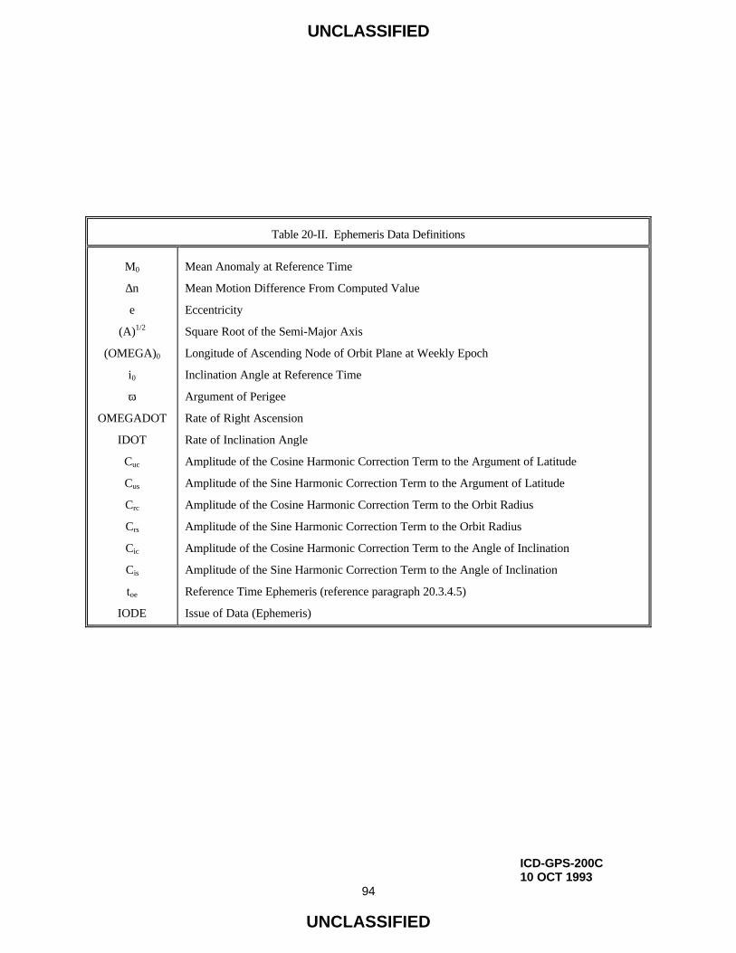
UNCLASSIFIED
ICD-GPS-200C10 OCT 1993
94
UNCLASSIFIED
Table 20-II. Ephemeris Data Definitions
M0
∆n
e
(A)1/2
(OMEGA)0
i0
ω
OMEGADOT
IDOT
Cuc
Cus
Crc
Crs
Cic
Cis
toe
IODE
Mean Anomaly at Reference Time
Mean Motion Difference From Computed Value
Eccentricity
Square Root of the Semi-Major Axis
Longitude of Ascending Node of Orbit Plane at Weekly Epoch
Inclination Angle at Reference Time
Argument of Perigee
Rate of Right Ascension
Rate of Inclination Angle
Amplitude of the Cosine Harmonic Correction Term to the Argument of Latitude
Amplitude of the Sine Harmonic Correction Term to the Argument of Latitude
Amplitude of the Cosine Harmonic Correction Term to the Orbit Radius
Amplitude of the Sine Harmonic Correction Term to the Orbit Radius
Amplitude of the Cosine Harmonic Correction Term to the Angle of Inclination
Amplitude of the Sine Harmonic Correction Term to the Angle of Inclination
Reference Time Ephemeris (reference paragraph 20.3.4.5)
Issue of Data (Ephemeris)

UNCLASSIFIED
IRN-200C-002ICD-GPS-200C25 SEP 1997
95
UNCLASSIFIED
The issue of ephemeris data (IODE) term shall provide the user with a convenient means for detecting any change in
the ephemeris representation parameters. The IODE is provided in both subframes 2 and 3 for the purpose of
comparison with the 8 LSBs of the IODC term in subframe 1. Whenever these three terms do not match, a data set
cutover has occurred and new data must be collected. The timing of the IODE and constraints on the IODC and
IODE are defined in paragraph 20.3.4.4.
Any change in the subframe 2 and 3 data will be accomplished with a simultaneous change in both IODE words.
The CS shall assure that the toe value, for at least the first data set transmitted by an SV after an upload, is different
from that transmitted prior to the cutover.
A "fit interval" flag is provided in subframe 2 to indicate whether the ephemerides are based on a four-hour fit
interval or a fit interval greater than four hours (reference paragraph 20.3.3.4.3.1).
The AODO word is provided in subframe 2 to enable the user to determine the validity time for the NMCT data
provided in subframe 4 of the transmitting SV. The related algorithm is given in paragraph 20.3.3.4.4.
20.3.3.4.2 Subframe 2 and 3 Parameter Characteristics. For each ephemeris parameter contained in subframes 2
and 3, the number of bits, the scale factor of the LSB (which shall be the last bit received), the range, and the units
shall be as specified in Table 20-III.
The AODO word (which is not an ephemeris parameter) is a five-bit unsigned term with an LSB scale factor of
900, a range from 0 to 31, and units of seconds.

UNCLASSIFIED
ICD-GPS-200C10 OCT 1993
96
UNCLASSIFIED
Table 20-III. Ephemeris Parameters
Parameter No. of Bits** Scale Factor (LSB) Effective Range*** Units
IODE
Crs
∆n
M0
Cuc
e
Cus
(A)1/2
toe
Cic
(OMEGA)0
Cis
i0
Crc
ω
OMEGADOT
IDOT
8
16*
16*
32*
16*
32
16*
32
16
16*
32*
16*
32*
16*
32*
24*
14*
2-5
2-43
2-31
2-29
2-33
2-29
2-19
24
2-29
2-31
2-29
2-31
2-5
2-31
2-43
2-43
0.03
604,784
(see text)
meters
semi-circles/sec
semi-circles
radians
dimensionless
radians
meters1/2
seconds
radians
semi-circles
radians
semi-circles
meters
semi-circles
semi-circles/sec
semi-circles/sec
* Parameters so indicated shall be two's complement, with the sign bit (+ or -) occupying the MSB; ** See Figure 20-1 for complete bit allocation in subframe;*** Unless otherwise indicated in this column, effective range is the maximum range attainable with
indicated bit allocation and scale factor.

UNCLASSIFIED
IRN-200C-003ICD-GPS-200C11 OCT 1999
97
UNCLASSIFIED
20.3.3.4.3 User Algorithm for Ephemeris Determination. The user shall compute the ECEF coordinates of position
for the phase center of the SVs’ antennas utilizing a variation of the equations shown in Table 20-IV. Subframes 2
and 3 parameters are Keplerian in appearance; the values of these parameters, however, are produced by the CS via
a least squares curve fit of the predicted ephemeris of the phase center of the SVs’ antennas (time-position
quadruples; t, x, y, z expressed in ECEF coordinates). Particulars concerning the periods of the curve fit, the
resultant accuracy, and the applicable coordinate system are given in the following subparagraphs.
20.3.3.4.3.1 Curve Fit Intervals. Bit 17 in word 10 of subframe 2 is a "fit interval" flag which indicates the curve-
fit interval used by the CS in determining the ephemeris parameters, as follows:
0 = 4 hours,
1 = greater than 4 hours.
The relationship of the curve-fit interval to transmission time and the timing of the curve-fit intervals is covered in
section 20.3.4.

UNCLASSIFIED
ICD-GPS-200C10 OCT 1993
98
UNCLASSIFIED
Table 20-IV. Elements of Coordinate Systems (sheet 1 of 3)
µ = 3.986005 x 10¹⁴ meters3/sec2 WGS 84 value of the earth's universal gravitational
parameter
Ω•
e = 7.2921151467 x 10⁻⁵ rad/sec WGS 84 value of the earth's rotation rate
A = ( )2 A Semi-major axis
n0 = 3A
µComputed mean motion (rad/sec)
tk = t - toe* Time from ephemeris reference epoch
n = n0 + ∆n Corrected mean motion
Mk = M0 + ntk Mean anomaly
* t is GPS system time at time of transmission, i.e., GPS time corrected for transit time (range/speed of
light). Furthermore, tk shall be the actual total time difference between the time t and the epoch time
toe, and must account for beginning or end of week crossovers. That is, if tk is greater than 302,400
seconds, subtract 604,800 seconds from tk. If tk is less than -302,400 seconds, add 604,800 seconds to
tk.

UNCLASSIFIED
ICD-GPS-200C10 OCT 1993
99
UNCLASSIFIED
Table 20-IV. Elements of Coordinate Systems (sheet 2 of 3)
Mk = Ek - e sin Ek Kepler's Equation for Eccentric Anomaly(may be solved by iteration)(radians)
νν
=ν −
k
k1k cos
sintan True Anomaly
( )
( ) ( )
−−−−
= −
kk
kk2
1
Ecose1 / eEcos
Ecose1 /Esine1tan
ν+ν+
= −
k
k1k cose1
cosecosE Eccentric Anomaly
Φk = νk + ω Argument of Latitude
δuk = cussin2Φk + cuccos2Φk Argument of Latitude Correctionδrk = crssin2Φk + crccos2Φk Radius Correctionδik = cissin2Φk + ciccos2Φk Inclination Correction
uk = Φk + δuk Corrected Argument of Latitude
rk = A(1 - e cosEk) + δrk Corrected Radius
ik = i0 + δik + (IDOT) tk Corrected Inclination
Second Harmonic Perturbations

UNCLASSIFIED
ICD-GPS-200C10 OCT 1993
100
UNCLASSIFIED
Table 20-IV. Elements of Coordinate Systems (sheet 3 of 3)
xk′ = rkcosuk
yk′ = rksinuk
Ωk = Ω0 + ( Ω•
- Ω•
e ) tk - Ω•
e toe Corrected longitude of ascending node.
xk = xk′cosΩk - yk′cosiksinΩk
yk = xk′sinΩk + yk′cosikcosΩk
zk = yk′sinik Earth-fixed coordinates.
Positions in orbital plane.

UNCLASSIFIED
IRN-200C-003ICD-GPS-200C11 OCT 1999
101
UNCLASSIFIED
20.3.3.4.3.2 Parameter Sensitivity. The sensitivity of the SV's antenna phase center position to small
perturbations in most ephemeris parameters is extreme. The sensitivity of position to the parameters (A)1/2, Crc
and Crs is about one meter/meter. The sensitivity of position to the angular parameters is on the order of 108
meters/semicircle, and to the angular rate parameters is on the order of 1012 meters/semicircle/second. Because of
this extreme sensitivity to angular perturbations, the value of π used in the curve fit is given here. π is a
mathematical constant, the ratio of a circle's circumference to its diameter. Here π is taken as
π = 3.1415926535898.
20.3.3.4.3.3 Coordinate Systems.
20.3.3.4.3.3.1 ECEF Coordinate System. The equations given in Table 20-IV provide the SV's antenna phase
center position in the WGS 84 ECEF coordinate system defined as follows:
ORIGIN = Earth's center of mass*
Z-AXIS = Parallel to the direction of the CONVENTIONAL INTERNATIONAL ORIGIN (CIO)
for polar motion, as defined by the BUREAU INTERNATIONAL DE L'HEURE (BIH)
on the basis of the latitudes adopted for the BIH stations**
X-AXIS = Intersection of the WGS 84 reference meridian plane and the plane of the mean
astronomic equator, the reference meridian being parallel to the zero meridian defined
by the BUREAU INTERNATIONAL DE L'HEURE (BIH) on the basis of the longitudes
adopted for the BIH stations***
Y-AXIS = Completes a right-handed, earth-centered, earth-fixed orthogonal coordinate system,
measured in the plane of the mean astronomic equator 90° east of the X-axis***
* Geometric center of WGS 84 ellipsoid
** Rotation axis of WGS 84 ellipsoid
*** X, Y axes of WGS 84 ellipsoid

UNCLASSIFIED
IRN-200C-003ICD-GPS-200C11 OCT 1999
102
UNCLASSIFIED
20.3.3.4.3.3.2 Earth-Centered, Inertial (ECI) Coordinate System. In an ECI coordinate system, GPS signals
propagate in straight lines at the constant speed c* (reference paragraph 20.3.4.3). A stable ECI coordinate system
of convenience may be defined as being coincident with the ECEF coordinate system at a given time t0. The x, y, z
coordinates in the ECEF coordinate system at some other time t can be transformed to the x′, y′, z′ coordinates in the
selected ECI coordinate system of convenience by the simple** rotation:
x′ = x cos(θ) – y sin(θ)
y′ = x sin(θ) + y cos(θ)
z′ = z
where
θ = Ω•
e (t – t0)
* The propagation speed c is constant only in a vacuum. The gravitational potential also has a small
effect on the propagation speed, but may be neglected by most users.
** Neglecting effects due to polar motion, nutation, and precession which may be neglected by most users
for small values of (t – t0).
20.3.3.4.3.4 Geometric Range. The user shall account for the geometric range (D) from satellite to receiver in an
ECI coordinate system. D may be expressed as,
D = | →r (tR) -
→R(tT)|
where
tT and tR are the GPS system times of transmission and reception, respectively,
and where,
→R(tT) = position vector of the GPS satellite in the selected ECI coordinate system at time tT,
→r (tR) = position vector of the receiver in the selected ECI coordinate system at time tR.

UNCLASSIFIED
IRN-200C-003ICD-GPS-200C11 OCT 1999
102a
UNCLASSIFIED
20.3.3.4.4 NMCT Validity Time. Users desiring to take advantage of the NMCT data provided in page 13 of
subframe 4 shall first examine the AODO term currently provided in subframe 2 of the NAV data from the
transmitting SV. If the AODO term is 27900 seconds (i.e., binary 11111), then the NMCT currently available
from the transmitting SV is invalid and shall not be used. If the AODO term is less than 27900 seconds, then the
user shall compute the validity time for that NMCT (tnmct) using the ephemeris toe parameter and the AODO term
from the current subframe 2 as follows:
OFFSET = toe [Modulo 7200]
if OFFSET = 0, then tnmct = toe - AODO
if OFFSET > 0, then tnmct = toe - OFFSET + 7200 - AODO
Note that the foregoing computation of tnmct must account for any beginning or end of week crossovers; for
example,
if t* - tnmct > 302,400 then tnmct = tnmct + 604,800
if t* - tnmct < -302,400 then tnmct = tnmct - 604,800
* t is GPS system time at time of transmission.
Users are advised that different SVs will transmit NMCTs with different tnmct and that the best performance will
generally be obtained by applying data from the NMCT with the latest (largest) tnmct. As a result, users should
compute and examine the tnmct values for all visible and available SVs in order to find and use the NMCT with the
latest tnmct. If the same latest (largest) tnmct is provided by two or more visible and available SVs, then the NMCT
from any SV with the latest tnmct may be selected and used; however, the estimated range deviation (ERD) value
provided by the selected NMCT for the other SVs with the same tnmct shall be set to zero if those SVs are used in
the positioning solution. It should be noted that the intended positioning solution accuracy improvement will not be
obtained if the data from two different NMCTs are applied simultaneously or if the data from a given NMCT is
applied to just a subset of the SVs used in the positioning solution (i.e., mixed mode operation results in potentially
degraded solution accuracy).
It should be noted that the NMCT information shall be supported by the Block IIR SV only when operating in the
IIA like mode of operation including the Autonav Test mode.

UNCLASSIFIED
IRN-200C-003ICD-GPS-200C11 OCT 1999
102b
UNCLASSIFIED
20.3.3.5 Subframes 4 and 5. Both subframe 4 and 5 are subcommutated 25 times each; the 25 versions of these
subframes are referred to as pages 1 through 25 of each subframe. With the possible exception of "reserved for
system use" pages and explicit repeats, each page contains different specific data in words three through ten. As
shown in Figure 20-1, the pages of subframe 4 utilize seven different formats, while those of subframe 5 use two.
The content of words three through ten of each page is described below, followed by algorithms and material
pertinent to the use of the data.
20.3.3.5.1 Content of Subframes 4 and 5. Words three through ten of each page contain six parity bits as their
LSBs; in addition, two non-information bearing bits are provided as bits 23 and 24 of word ten in each page for
parity computation purposes. The data contained in the remaining bits of words three through ten of the various
pages in subframes 4 and 5 are described in the following subparagraphs.

UNCLASSIFIED
IRN-200C-002ICD-GPS-200C25 SEP 1997
103
UNCLASSIFIED
A brief summary of the various data contained in each page of subframes 4 and 5 is as follows:
a. Subframe 4:
• Pages 1, 6, 11, 16 and 21: (reserved);
• Pages 2, 3, 4, 5, 7, 8, 9 and 10: almanac data for SV 25 through 32 respectively.
These pages may be designated for other functions; the format and content for each
page is defined by the SV ID of that page. In this case, the six-bit health word of page
25 is set to "6 ones" (Refer to 20.3.3.5.1.3) and the SV ID of the page will not have a
value in the range of 25 through 32;
• Pages 12, 19, 20, 22, 23 and 24: (reserved);
• Page 13: NMCT;
• Pages 14 and 15: reserved for system use;
• Page 17: special messages;
• Page 18: ionospheric and UTC data;
• Page 25: A-S flags/SV configurations for 32 SVs, plus SV health for SV 25
through 32.
b. Subframe 5:
• Pages 1 through 24: almanac data for SV 1 through 24;
• Page 25: SV health data for SV 1 through 24, the almanac reference time and
the almanac reference week number.

UNCLASSIFIED
ICD-GPS-200C10 OCT 1993
104
UNCLASSIFIED
20.3.3.5.1.1 Data ID and SV ID. The two MSBs of word three in each page shall contain the data ID which
defines the applicable GPS NAV data structure. Data ID one (denoted by binary code 00) was utilized during
Phase I of the GPS program and is no longer in use; data ID two (denoted by binary code 01) is described in this
Appendix. Future data IDs will be defined as necessary.
As shown in Table 20-V, the data ID is utilized to provide one of two indications: (a) for those pages which are
assigned to contain the almanac data of one specific SV, the data ID defines the data structure utilized by that SV
whose almanac data are contained in that page; and (b) for all other pages, the data ID denotes the data structure of
the transmitting SV.
The SV ID is given by bits three through eight of word three in each page as shown in Table 20-V. Specific IDs
are reserved for each page of subframes 4 and 5; however, the SV ID of pages 2, 3, 4, 5, 7, 8, 9 and 10 of subframe
4 may change for each page to reflect the alternate contents for that page. The SV IDs are utilized in two different
ways: (a) for those pages which contain the almanac data of a given SV, the SV ID is the same number that is
assigned to the PRN code phase of that SV (reference Table 3-I), and (b) for all other pages the SV ID assigned in
accordance with Table 20-V serves as the "page ID". IDs 1 through 32 are assigned to those pages which contain
the almanac data of specific SVs (pages 1-24 of subframe 5 and pages 2-5 and 7-10 of subframe 4). The "0" ID
(binary all zeros) is assigned to indicate a dummy SV, while IDs 51 through 63 are utilized for pages containing
other than almanac data of a specific SV. The remaining IDs (33 through 50) are unassigned.
Pages which contain identical data (for more frequent repetition) carry the same SV ID (e.g., in subframe 4, pages
1, 6, 11, 16 and 21 carry an ID of 57, while pages 12 and 24 are designated by an ID of 62).

UNCLASSIFIED
ICD-GPS-200C10 OCT 1993
105
UNCLASSIFIED
Table 20-V. Data IDs and SV IDs in Subframes 4 and 5
PageSubframe 4 Subframe 5
Data ID SV ID* Data ID SV ID*
12 Note(3)3 Note(3)4 Note(3)5 Note(3)
67 Note(3)8 Note(3)9 Note(3)10 Note(3)
111213141516171819202122232425
Note(2)Note(1)Note(1)Note(1)Note(1)Note(2)Note(1)Note(1)Note(1)Note(1)Note(2)Note(2)Note(2)Note(2)Note(2)Note(2)Note(2)Note(2)Note(2)Note(2)Note(2)Note(2)Note(2)Note(2)Note(2)
572526272857293031325762525354575556
58 Note(4)59 Note(4)
5760 Note(4)61 Note(4)
6263
Note(1)Note(1)Note(1)Note(1)Note(1)Note(1)Note(1)Note(1)Note(1)Note(1)Note(1)Note(1)Note(1)Note(1)Note(1)Note(1)Note(1)Note(1)Note(1)Note(1)Note(1)Note(1)Note(1)Note(1)Note(2)
12345678910111213141516171819202122232451
* Use "0" to indicate "dummy" SV. When using "0" to indicate dummy SV, use the data ID of the transmittingSV.
Note 1: Data ID of that SV whose SV ID appears in that page.Note 2: Data ID of transmitting SV.Note 3: Pages 2, 3, 4, 5, 7, 8, 9, and 10 of subframe 4 may contain almanac data for SVs 25 through 32,
respectively, or data for other functions as identified by a different SV ID from the value shown.Note 4: SV ID may vary.

UNCLASSIFIED
ICD-GPS-200C10 OCT 1993
106
UNCLASSIFIED
20.3.3.5.1.2 Almanac Data. Pages 1 through 24 of subframe 5, as well as pages 2 through 5 and 7 through 10 of
subframe 4 contain the almanac data and a SV health word for up to 32 SVs (the health word is discussed in
paragraph 20.3.3.5.1.3). The almanac data are a reduced-precision subset of the clock and ephemeris parameters.
The data occupy all bits of words three through ten of each page except the eight MSBs of word three (data ID and
SV ID), bits 17 through 24 of word five (SV health), and the 50 bits devoted to parity. The number of bits, the
scale factor (LSB), the range, and the units of the almanac parameters are given in Table 20-VI. The algorithms
and other material related to the use of the almanac data are given in paragraph 20.3.3.5.2.
The almanac message for any dummy SVs shall contain alternating ones and zeros with valid parity. For twelve or
fewer SVs, almanacs may be repeated within the 25-cycle subcommutation limit. Whenever this option is
exercised, the following constraints shall apply: (a) each page of subframes 4 and 5, which is assigned by Table
20-V to one of the active SVs in orbit, must contain the almanac data of that SV to which it is assigned by Table
20-V, (b) those almanac-type pages which remain unused per the above rule, shall then be re-assigned to carry a
duplicate set of almanac data for the active orbiting SV, (c) these page re-assignments shall be in ascending order
of page numbers (starting with subframe 5, followed by subframe 4) being used for SVs having an ascending order
of SV IDs, and (d) each re-assigned page must carry the SV ID of that SV whose almanac data it contains.
The almanac parameters shall be updated by the CS at least once every 6 days while the CS is able to upload the
SVs. If the CS is unable to upload the SVs, the accuracy of the almanac parameters transmitted by the SVs will
degrade over time.

UNCLASSIFIED
ICD-GPS-200C10 OCT 1993
107
UNCLASSIFIED
For Block I SVs, one or two sets of almanac data is uploaded to cover the 3-4 days of valid data transmission. For
Block II and IIA SVs, three sets of almanac shall be used to span 182 days. The first and second sets will be
transmitted for up to six days each; the third set is intended to be transmitted for the duration of the 182 days from
the last upload, but the duration of transmission will depend on the individual SV's capability to retain data in
memory. All three sets are based on six-day curve fits that correspond to the first six days of the transmission
interval. For Block IIR SVs, multiple sets of almanac parameters shall be uploaded to span 210 days.

UNCLASSIFIED
ICD-GPS-200C10 OCT 1993
108
UNCLASSIFIED
Table 20-VI. Almanac Parameters
ParameterNo. ofBits**
ScaleFactor(LSB)
EffectiveRange*** Units
e
toa
δi****
OMEGADOT
(A)1/2
(OMEGA)0
ω
M0
af0
af1
16
8
16*
16*
24
24*
24*
24*
11*
11*
2-21
212
2-19
2-38
2-11
2-23
2-23
2-23
2-20
2-38
602,112
dimensionless
seconds
semi-circles
semi-circles/sec
meters1/2
semi-circles
semi-circles
semi-circles
seconds
sec/sec
* Parameters so indicated shall be two's complement with the sign bit (+ or -) occupying the MSB;
** See Figure 20-1 for complete bit allocation in subframe;
*** Unless otherwise indicated in this column, effective range is the maximum range attainable withindicated bit allocation and scale factor;
**** Relative to i0 = 0.30 semi-circles.

UNCLASSIFIED
ICD-GPS-200C10 OCT 1993
109
UNCLASSIFIED
20.3.3.5.1.3 SV Health. Subframes 4 and 5 contain two types of SV health data: (a) each of the 32 pages which
contain the clock/ephemeris related almanac data provide an eight-bit SV health status word regarding the SV
whose almanac data they carry, and (b) the 25th page of subframe 4 and of subframe 5 jointly contain six-bit health
status data for up to 32 SVs.
The three MSBs of the eight-bit health words indicate health of the NAV data in accordance with the code given in
Table 20-VII. The six-bit words provide a one-bit summary of the NAV data's health status in the MSB position in
accordance with paragraph 20.3.3.3.1.4. The five LSBs of both the eight-bit and the six-bit words provide the
health status of the SV's signal components in accordance with the code given in Table 20-VIII. A special
meaning is assigned, however, to the "6 ones" combination of the six-bit health words in the 25th page of
subframes 4 and 5: it indicates that "the SV which has that ID is not available and there may be no data regarding
that SV in that page of subframes 4 and 5 that is assigned to normally contain the almanac data of that SV"
(NOTE: (a) this special meaning applies to the 25th page of subframes 4 and 5 only; and (b) there may be data
regarding another SV in the almanac-page referred to above as defined in paragraph 20.3.3.5.1.1). The health
indication shall be given relative to the "as designed" capabilities of each SV (as designated by the configuration
code -- see paragraph 20.3.3.5.1.6). Accordingly, any SV which does not have a certain capability will be
indicated as "healthy" if the lack of this capability is inherent in its design or it has been configured into a mode
which is normal from a user standpoint and does not require that capability.

UNCLASSIFIED
ICD-GPS-200C10 OCT 1993
110
UNCLASSIFIED
Table 20-VII. NAV Data Health Indications
Bit Position in Page
Indication
137 138 139
0
0
0
0
1
1
1
1
0
0
1
1
0
0
1
1
0
1
0
1
0
1
0
1
ALL DATA OK
PARITY FAILURE -- some or all parity bad
TLM/HOW FORMAT PROBLEM -- any departure from standard format (e.g.,
preamble misplaced and/or incorrect, etc.), except for incorrect Z-count, as
reported in HOW
Z-COUNT IN HOW BAD -- any problem with Z-count value not reflecting
actual code phase
SUBFRAMES 1, 2, 3 -- one or more elements in words three through ten of
one or more subframes are bad
SUBFRAMES 4, 5 -- one or more elements in words three through ten of one
or more subframes are bad
ALL UPLOADED DATA BAD -- one or more elements in words three
through ten of any one (or more) subframes are bad
ALL DATA BAD -- TLM word and/or HOW and one or more elements in any
one (or more) subframes are bad

UNCLASSIFIED
ICD-GPS-200C10 OCT 1993
111
UNCLASSIFIED
Table 20-VIII. Codes for Health of SV Signal Components
MSB LSB Definition
0 0 0 0 00 0 0 0 10 0 0 1 00 0 0 1 10 0 1 0 00 0 1 0 10 0 1 1 00 0 1 1 10 1 0 0 00 1 0 0 10 1 0 1 00 1 0 1 10 1 1 0 00 1 1 0 10 1 1 1 00 1 1 1 11 0 0 0 01 0 0 0 11 0 0 1 01 0 0 1 11 0 1 0 01 0 1 0 11 0 1 1 01 0 1 1 11 1 0 0 01 1 0 0 11 1 0 1 01 1 0 1 11 1 1 0 01 1 1 0 11 1 1 1 01 1 1 1 1
All Signals OKAll Signals Weak*All Signals DeadAll Signals Have No Data ModulationL1 P Signal WeakL1 P Signal DeadL1 P Signal Has No Data ModulationL2 P Signal WeakL2 P Signal DeadL2 P Signal Has No Data ModulationL1 C Signal WeakL1 C Signal DeadL1 C Signal Has No Data ModulationL2 C Signal WeakL2 C Signal DeadL2 C Signal Has No Data ModulationL1 & L2 P Signal WeakL1 & L2 P Signal DeadL1 & L2 P Signal Has No Data ModulationL1 & L2 C Signal WeakL1 & L2 C Signal DeadL1 & L2 C Signal Has No Data ModulationL1 Signal Weak*L1 Signal DeadL1 Signal Has No Data ModulationL2 Signal Weak*L2 Signal DeadL2 Signal Has No Data ModulationSV Is Temporarily Out (Do not use this SV during current pass**)SV Will Be Temporarily Out (Use with caution**)SpareMore Than One Combination Would Be Required To Describe Anomalies (Except those markedby **)
* 3 to 6 dB below specified power level due to reduced power output, excess phase noise, SV attitude, etc.

UNCLASSIFIED
ICD-GPS-200C10 OCT 1993
112
UNCLASSIFIED
Additional SV health data are given in subframe 1. The data given in subframes 1, 4, and 5 of the other SVs may
differ from that shown in subframes 4 and/or 5 since the latter may be updated at a different time.
The eight-bit health status words shall occupy bits 17 through 24 of word five in those 32 pages which contain
almanac data for individual SVs. The six-bit health status words shall occupy the 24 MSBs of words four through
nine in page 25 of subframe 5 plus bits 19 through 24 of word 8, the 24 MSBs of word 9, and the 18 MSBs of word
10 in page 25 of subframe 4.
The predicted health data will be updated at the time of upload when a new almanac has been built by the CS. The
transmitted health data may not correspond to the actual health of the transmitting SV or other SVs in the
constellation.
20.3.3.5.1.4 (Reserved).
20.3.3.5.1.5 (Reserved).
20.3.3.5.1.6 Anti-Spoof (A-S) Flags and SV Configurations. Page 25 of subframe 4 shall contain a four-bit-long
term for each of up to 32 SVs to indicate the A-S status and the configuration code of each SV. The MSB of each
four-bit term shall be the A-S flag with a "1" indicating that A-S is ON. The three LSBs shall indicate the
configuration of each SV using the following code:
Code SV Configuration
000 "Block I" SV (memory capacity for 3-4 days of uploaded data)
001 "Block II" SV (A-S capability, plus flags for A-S and "alert" in HOW; memory capacity
as described in paragraph 20.3.2).

UNCLASSIFIED
ICD-GPS-200C10 OCT 1993
113
UNCLASSIFIED
Additional codes will be assigned in the future, should the need arise.
These four-bit terms shall occupy bits 9 through 24 of word three, the 24 MSBs of words four through seven, and
the 16 MSBs of word eight, all in page 25 of subframe 4.
Since the anti-spoof information is updated by the CS at the time of upload, the anti-spoof data may not correspond
to the actual anti-spoof status of the transmitting SV or other SVs in the constellation.
20.3.3.5.1.7 Almanac Reference Week. Bits 17 through 24 of word three in page 25 of subframe 5 shall indicate
the number of the week (WNa) to which the almanac reference time (toa) is referenced (see paragraphs 20.3.3.5.1.2
and 20.3.3.5.2.2). The WNa term consists of the eight LSBs of the full week number. Bits 9 through 16 of word
three in page 25 of subframe 5 shall contain the value of toa which is referenced to this WNa.
20.3.3.5.1.8 Universal Coordinated Time (UTC) Parameters. The 24 MSBs of words six through nine plus the
eight MSBs of word ten in page 18 of subframe 4 shall contain the parameters related to correlating UTC time with
GPS time. The bit length, scale factors, ranges, and units of these parameters are given in Table 20-IX. The
related algorithms are described in paragraph 20.3.3.5.2.4.

UNCLASSIFIED
ICD-GPS-200C10 OCT 1993
114
UNCLASSIFIED
The UTC parameters shall be updated by the CS at least once every six days while the CS is able to upload the
SVs. If the CS is unable to upload the SVs, the accuracy of the UTC parameters transmitted by the SVs will
degrade over time.
20.3.3.5.1.9 Ionospheric Data. The ionospheric parameters which allow the "L1 only" or "L2 only" user to utilize
the ionospheric model (reference paragraph 20.3.3.5.2.5) for computation of the ionospheric delay are contained in
page 18 of subframe 4. They occupy bits 9 through 24 of word three plus the 24 MSBs of words four and five. The
bit lengths, scale factors, ranges, and units of these parameters are given in Table 20-X.
The ionospheric data shall be updated by the CS at least once every six days while the CS is able to upload the
SVs. If the CS is unable to upload the SVs, the ionospheric data transmitted by the SVs may not be accurate.

UNCLASSIFIED
ICD-GPS-200C10 OCT 1993
115
UNCLASSIFIED
Table 20-IX. UTC Parameters
Parameter
No. of
Bits**
Scale
Factor
(LSB)
Effective
Range*** Units
A0
A1
∆ tLS
tot
WNt
WNLSF
DN
∆ tLSF
32*
24*
8*
8
8
8
8****
8*
2-30
2-50
1
212
1
1
1
1
602,112
7
Seconds
sec/sec
seconds
seconds
weeks
weeks
days
seconds
* Parameters so indicated shall be two's complement with the sign bit (+ or -) occupying the MSB;
** See Figure 20-1 for complete bit allocation in subframe;
*** Unless otherwise indicated in this column, effective range is the maximum range attainable with
indicated bit allocation and scale factor;
**** Right justified.

UNCLASSIFIED
ICD-GPS-200C10 OCT 1993
116
UNCLASSIFIED
Table 20-X. Ionospheric Parameters
Parameter
No. of
Bits**
Scale
Factor
(LSB)
Effective
Range*** Units
α 0
α 1
α 2
α 3
β 0
β 1
β 2
β 3
8*
8*
8*
8*
8*
8*
8*
8*
2-30
2-27
2-24
2-24
211
214
216
216
Seconds
sec/semi-circle
sec/(semi-circle)2
sec/(semi-circle)3
seconds
sec/semi-circle
sec/(semi-circle)2
sec/(semi-circle)3
* Parameters so indicated shall be two's complement with the sign bit (+ or -) occupying the MSB;
** See Figure 20-1 for complete bit allocation in subframe;
*** Unless otherwise indicated in this column, effective range is the maximum range attainable with
indicated bit allocation and scale factor.

UNCLASSIFIED
IRN-200C-002ICD-GPS-200C25 SEP 1997
117
UNCLASSIFIED
20.3.3.5.1.10 Special Messages. Page 17 of subframe 4 shall be reserved for special messages with the specific
contents at the discretion of the Operating Command. It shall accommodate the transmission of 22 eight-bit ASCII
characters. The requisite 176 bits shall occupy bits 9 through 24 of word three, the 24 MSBs of words four through
nine, plus the 16 MSBs of word ten. The eight MSBs of word three shall contain the data ID and SV ID, while bits
17 through 22 of word ten shall be reserved for system use. The remaining 50 bits of words three through ten are
used for parity (six bits/word) and parity computation (two bits in word ten). The eight-bit ASCII characters shall
be limited to the following set:
Alphanumeric Character ASCII Character Code (Octal)
A - Z A - Z 101 - 132
0 - 9 0 - 9 060 - 071
+ + 053
- - 055
. (Decimal point) . 056
' (Minute mark) ' 047
° (Degree sign) ° 370
/ / 057
Blank Space 040
: : 072
" (Second mark) " 042

UNCLASSIFIED
IRN-200C-002ICD-GPS-200C25 SEP 1997
118
UNCLASSIFIED
20.3.3.5.1.11 (Deleted)
20.3.3.5.1.12 NMCT. Page 13 of subframe 4 shall contain the NMCT data appropriate to the transmitting SV.
Each NMCT contains a two-bit availability indicator (AI) followed by 30 slots which may contain up to 30 valid
six-bit ERD values. The layout of these 31 data items is as shown in Figure 20-1.
The two-bit AI in bits 9 and 10 of word three of page 13 of subframe 4 provide the user with the following
information.
AI Navigation Message Correction Table Availability
00 The correction table is unencrypted and is available to both authorized and unauthorized users.
01 The correction table is encrypted and is available only to authorized users (normal mode).
10 No correction table available for either authorized or unauthorized users.
11 Reserved.
Each one of the 30 six-bit ERD slots in bits 11 through 24 of word three, bits 1 through 24 of words four through
nine, and bits 1 through 22 of word ten of page 13 of subframe 4 will correspond to an ERD value for a particular
SV ID. There are 31 possible SV IDs that these ERD slots may correspond to, ranging from SV ID 1 to SV ID 31.
SV ID 32 is not a valid SV ID for any of the slots in an NMCT. The correspondence between the 30 ERD slots
and the 31 possible SV IDs depends on the SV ID of the particular transmitting SV in accordance with the
following two rules: 1) the CS shall ensure via upload that no SV shall transmit an NMCT containing an ERD
value which applies to its own SV ID, and 2) the CS shall ensure via upload that all ERD values shall be
transmitted in ascending numerical slot order of the corresponding SV ID. To illustrate: the SV operating as SV
ID 1 will transmit (in order) ERD values which correspond to SV ID 2 through SV ID 31 in ERD slots 1 through
30 respectively, while the SV operating as SV ID 31 will transmit ERD values which correspond to SV ID 1
through SV ID 30 in ERD slots 1 through 30 respectively.

UNCLASSIFIED
IRN-200C-002ICD-GPS-200C25 SEP 1997
118a
UNCLASSIFIED
Each ERD value contained in an NMCT ERD slot shall be represented as a six-bit two’s complement field with the
sign bit occupying the MSB and an LSB of 0.3 meters for an effective range of ±9.3 m. A binary value of
“100000” shall indicate that no valid ERD for the corresponding SV ID is present in that slot.
20.3.3.5.2 Algorithms Related to Subframe 4 and 5 Data. The following algorithms shall apply when interpreting
Almanac, Universal Coordinated Time, Ionospheric Model, and NMCT data in the NAV message.
20.3.3.5.2.1 Almanac. The almanac is a subset of the clock and ephemeris data, with reduced precision. The user
algorithm is essentially the same as the user algorithm used for computing the precise ephemeris from the one
subframe 1, 2, and 3 parameters (see Table 20-IV). The almanac content for one SV is given in Table 20-VI. A
close inspection of Table 20-VI will reveal that a nominal inclination angle of 0.30 semicircles is implicit and that
the parameter δ i (correction to inclination) is transmitted, as opposed to the value computed by the user. All other
parameters appearing in the equations of Tables 20-IV, but not included in the content of the almanac, are set to
zero for SV position determination. In these respects, the application of the Table 20-IV equations differs between
the almanac and the ephemeris computations.

UNCLASSIFIED
IRN-200C-002ICD-GPS-200C25 SEP 1997
118b
UNCLASSIFIED
(This page intentionally left blank.)

UNCLASSIFIED
IRN-200C-002ICD-GPS-200C25 SEP 1997
119
UNCLASSIFIED
Table 20-XI. (Deleted)

UNCLASSIFIED
ICD-GPS-200C10 OCT 1993
120
UNCLASSIFIED
The user is cautioned that the sensitivity to small perturbations in the parameters is even greater for the almanac
than for the ephemeris, with the sensitivity of the angular rate terms over the interval of applicability on the order
of 1014 meters/(semicircle/second). An indication of the URE provided by a given almanac during each of the
operational intervals is as follows:
Almanac Ephemeris URE
(estimated by analysis)
Operational Interval 1 sigma (meters)
Normal 900*,†
Short-term Extended 900 - 3,600*Long-term Extended 3600 - 300,000*
* URE values generally tend to degrade quadratically over time. Larger errors may be encountered
during eclipse seasons and whenever a propulsive event has occurred.
†After the CS is unable to upload the SVs, URE values for the Block IIR SVs operating in the
Autonav mode tend to degrade quadratically such that the URE will approach 300,000 meters 1
sigma at 180 days.
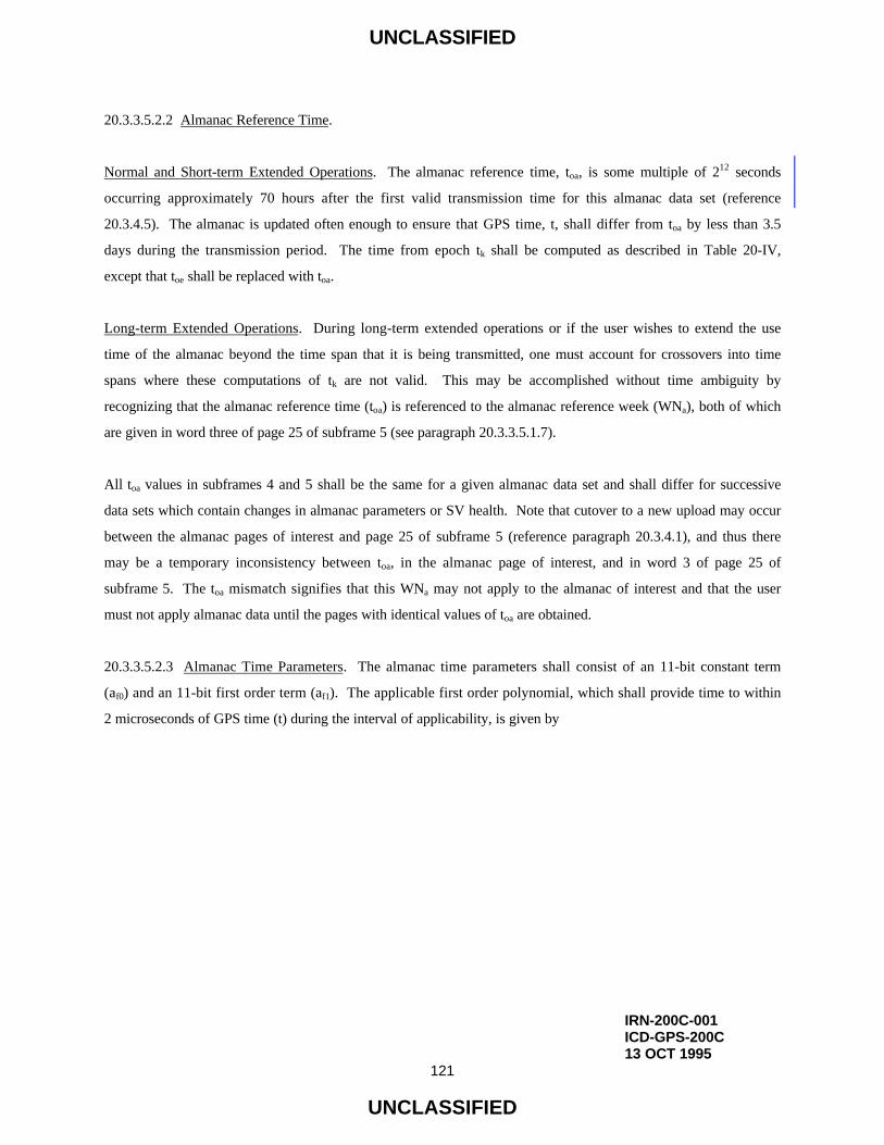
UNCLASSIFIED
IRN-200C-001ICD-GPS-200C13 OCT 1995
121
UNCLASSIFIED
20.3.3.5.2.2 Almanac Reference Time.
Normal and Short-term Extended Operations. The almanac reference time, toa, is some multiple of 212 seconds
occurring approximately 70 hours after the first valid transmission time for this almanac data set (reference
20.3.4.5). The almanac is updated often enough to ensure that GPS time, t, shall differ from toa by less than 3.5
days during the transmission period. The time from epoch tk shall be computed as described in Table 20-IV,
except that toe shall be replaced with toa.
Long-term Extended Operations. During long-term extended operations or if the user wishes to extend the use
time of the almanac beyond the time span that it is being transmitted, one must account for crossovers into time
spans where these computations of tk are not valid. This may be accomplished without time ambiguity by
recognizing that the almanac reference time (toa) is referenced to the almanac reference week (WNa), both of which
are given in word three of page 25 of subframe 5 (see paragraph 20.3.3.5.1.7).
All toa values in subframes 4 and 5 shall be the same for a given almanac data set and shall differ for successive
data sets which contain changes in almanac parameters or SV health. Note that cutover to a new upload may occur
between the almanac pages of interest and page 25 of subframe 5 (reference paragraph 20.3.4.1), and thus there
may be a temporary inconsistency between toa, in the almanac page of interest, and in word 3 of page 25 of
subframe 5. The toa mismatch signifies that this WNa may not apply to the almanac of interest and that the user
must not apply almanac data until the pages with identical values of toa are obtained.
20.3.3.5.2.3 Almanac Time Parameters. The almanac time parameters shall consist of an 11-bit constant term
(af0) and an 11-bit first order term (af1). The applicable first order polynomial, which shall provide time to within
2 microseconds of GPS time (t) during the interval of applicability, is given by

UNCLASSIFIED
IRN-200C-003ICD-GPS-200C11 OCT 1999
122
UNCLASSIFIED
t = tsv - ∆tsv
where
t = GPS system time (seconds),
tsv = effective SV PRN code phase time at message transmission time
(seconds),
∆tsv = SV PRN code phase time offset (seconds).
The SV PRN code phase offset is given by
∆tsv = af0 + af1 tk
where the computation of tk is described in paragraph 20.3.3.5.2.2, and the polynomial coefficients af0 and af1 are
given in the almanac. Since the periodic relativistic effect is less than 25 meters, it need not be included in the
time scale used for almanac evaluation. Over the span of applicability, it is expected that the almanac time
parameters will provide a statistical URE component of less than 135 meters, one sigma. This is partially due to
the fact that the error caused by the truncation of af0 and af1 may be as large as 150 meters plus 50 meters/day
relative to the toa reference time.
During extended operations (short-term and long-term) the almanac time parameter may not provide the specified
time accuracy or URE component.
20.3.3.5.2.4 Universal Coordinated Time (UTC). Page 18 of subframe 4 includes: (1) the parameters needed to
relate GPS time to UTC, and (2) notice to the user regarding the scheduled future or recent past (relative to NAV
message upload) value of the delta time due to leap seconds (∆tLSF), together with the week number (WNLSF) and
the day number (DN) at the end of which the leap second becomes effective. "Day one" is the first day relative to
the end/start of week and the WNLSF value consists of the eight LSBs of the full week number. The user must
account for the truncated nature of this parameter as well as truncation of WN, WNt, and WNLSF due to rollover of
the full week number (see paragraph 3.3.4(b)). The CS shall manage these parameters such that the absolute value
of the difference between the untruncated WN and WNLSF values shall not exceed 127.

UNCLASSIFIED
IRN-200C-003ICD-GPS-200C11 OCT 1999
123
UNCLASSIFIED
Depending upon the relationship of the effectivity date to the user's current GPS time, the following three different
UTC/GPS-time relationships exist:
a. Whenever the effectivity time indicated by the WNLSF and the DN values is not in the past (relative to
the user's present time), and the user's present time does not fall in the time span which starts at DN + 3/4 and
ends at DN + 5/4, the UTC/GPS-time relationship is given by
tUTC = (tE - ∆tUTC) [Modulo 86400 seconds]
where tUTC is in seconds and
∆tUTC = ∆tLS + A0 + A1 (tE - tot + 604800 (WN - WNt)), seconds;
tE = GPS time as estimated by the user on the basis of correcting tSV for factors
described in paragraph 20.3.3.3.3 as well as for ionospheric and SA (dither)
effects;
∆tLS = delta time due to leap seconds;
A0 and A1 = constant and first order terms of polynomial;
tot = reference time for UTC data (reference 20.3.4.5);
WN = current week number (derived from subframe 1);
WNt = UTC reference week number.
The estimated GPS time (tE) shall be in seconds relative to end/start of week. The reference time for UTC data (tot)
shall be referenced to the start of that week whose number (WNt) is given in word eight of page 18 in subframe 4.
The WNt value consists of the eight LSBs of the full week number. The user must account for the truncated nature
of this parameter as well as truncation of WN, WNt, and WNLSF due to rollover of the full week number (see
paragraph 3.3.4(b)). The CS shall manage these parameters such that the absolute value of the difference between
the untruncated WN and WNt values shall not exceed 127.

UNCLASSIFIED
ICD-GPS-200C10 OCT 1993
124
UNCLASSIFIED
b. Whenever the user's current time falls within the time span of DN + 3/4 to DN + 5/4, proper
accommodation of the leap second event with a possible week number transition is provided by the following
expression for UTC:
tUTC = W[Modulo (86400 + ∆tLSF - ∆tLS)], seconds;
where
W = (tE - ∆tUTC - 43200)[Modulo 86400] + 43200, seconds;
and the definition of ∆tUTC (as given in 20.3.3.5.2.4a above) applies throughout the transition period. Note that
when a leap second is added, unconventional time values of the form 23:59:60.xxx are encountered. Some user
equipment may be designed to approximate UTC by decrementing the running count of time within several
seconds after the event, thereby promptly returning to a proper time indication. Whenever a leap second event is
encountered, the user equipment must consistently implement carries or borrows into any year/week/day counts.
c. Whenever the effectivity time of the leap second event, as indicated by the WNLSF and DN values, is in
the "past" (relative to the user's current time), the relationship previously given for tUTC in 20.3.3.5.2.4a above is
valid except that the value of ∆tLSF is substituted for ∆tLS. The CS will coordinate the update of UTC parameters at
a future upload so as to maintain a proper continuity of the tUTC time scale.

UNCLASSIFIED
IRN-200C-003ICD-GPS-200C11 OCT 1999
125
UNCLASSIFIED
20.3.3.5.2.5 Ionospheric Model. The "two frequency" (L1 and L2) user shall correct the time received from the
SV for ionospheric effect by utilizing the time delay differential between L1 and L2 (reference paragraph
20.3.3.3.3.3). The "one frequency" user, however, may use the model given in Figure 20-4 to make this correction.
It is estimated that the use of this model will provide at least a 50 percent reduction in the single - frequency user's
RMS error due to ionospheric propagation effects. During extended operations, or for the Block IIR SVs in the
Autonav mode if the CS is unable to upload the SVs, the use of this model will yield unpredictable results.
20.3.3.5.2.6 NMCT Data. For each SV, the ERD value in the NMCT is an estimated pseudorange error. Each ERD
value is computed by the CS and represents the radial component of the satellite ephemeris error minus the speed of
light times the satellite clock error. The satellite ephemeris and clock errors are computed by subtracting the
broadcast from current estimates. Therefore, the ERD value may be used as follows to correct the user's measured
pseudorange:
PRc = PR – ERD
where,
PRc = pseudorange corrected with the ERD value from the NMCT
PR = measured pseudorange
Note that as described above, the ERD values are actually error estimates rather than differential corrections and so
are subtracted rather than added in the above equation.

UNCLASSIFIED
ICD-GPS-200C10 OCT 1993
126
UNCLASSIFIED
The ionospheric correction model is given by
( )
≥∗∗
<
+−+∗∗
=−
−
57.1 x , 100.5F
57.1x ,24
x
2
x1)AMP(100.5F
T
9
429
iono (sec)
where
Tiono is referred to the L1 frequency; if the user is operating on the L2 frequency, the correction term must
be multiplied by γ (reference paragraph 20.3.3.3.3.2),
=<
≥φα= ∑
=
0AMP ,0AMP if
0AMP ,AMP
3
0n
nmn (sec)
( )
PER
50400 -t 2 x
π= (radians)
=<
≥φβ= ∑
=
72,000PER ,000,72PER if
000,72PER ,PER
3
0n
nmn (sec)
F = 1.0 + 16.0 [0.53 - E]3
and αn and βn are the satellite transmitted data words with n = 0, 1, 2, and 3.
Figure 20-4. Ionospheric Model (Sheet 1 of 3)

UNCLASSIFIED
ICD-GPS-200C10 OCT 1993
127
UNCLASSIFIED
Other equations that must be solved are
φm = φi + 0.064cos(λi - 1.617) (semi-circles)
φψ
+λ=λi
ui cos
sinA (semi-circles)
−=φ−<φ+=φ+>φ
≤φ−ψ+φ
=φ0.416 then ,416.0 if
0.416 then ,416.0 if
0.416 circles),cosA(semi
ii
ii
iu
i (semi-circles)
0.022 - 0.11 E
0137.0
+=ψ (semi-circles)
t = 4.32 * 104λi + GPS time (sec)
where
0 ≤ t < 86400: therefore, if t ≥ 86400 seconds, subtract 86400 seconds;
if t < 0 seconds, add 86400 seconds.
Figure 20-4. Ionospheric Model (Sheet 2 of 3)

UNCLASSIFIED
ICD-GPS-200C10 OCT 1993
128
UNCLASSIFIED
The terms used in computation of ionospheric delay are as follows:
• Satellite Transmitted Terms
αn - the coefficients of a cubic equation representing the amplitude of the vertical
delay (4 coefficients - 8 bits each)
βn - the coefficients of a cubic equation representing the period of the model
(4 coefficients - 8 bits each)
• Receiver Generated Terms
E - elevation angle between the user and satellite (semi-circles)
A - azimuth angle between the user and satellite, measured clockwise positive from
the true North (semi-circles)
φu - user geodetic latitude (semi-circles) WGS-84
λu - user geodetic longitude (semi-circles) WGS-84
GPS time - receiver computed system time
• Computed Terms
X - phase (radians)
F - obliquity factor (dimensionless)
t - local time (sec)
φm - geomagnetic latitude of the earth projection of the ionospheric intersection
point (mean ionospheric height assumed 350 km) (semi-circles)
λi - geodetic longitude of the earth projection of the ionospheric intersection point
(semi-circles)
φi - geodetic latitude of the earth projection of the ionospheric intersection point
(semi-circles)
ψ - earth's central angle between the user position and the earth projection of
ionospheric intersection point (semi-circles)
Figure 20-4. Ionospheric Model (Sheet 3 of 3)

UNCLASSIFIED
IRN-200C-001ICD-GPS-200C13 OCT 1995
129
UNCLASSIFIED
20.3.4 Timing Relationships. The following conventions shall apply.
20.3.4.1 Paging and Cutovers. At end/start of week (a) the cyclic paging of subframes 1 through 5 shall restart
with subframe 1 regardless of which subframe was last transmitted prior to end/start of week, and (b) the cycling of
the 25 pages of subframes 4 and 5 shall restart with page 1 of each of the subframes, regardless of which page was
the last to be transmitted prior to the end/start of week. Cutovers to newly updated data for subframes 1, 2, and 3
occur on frame boundaries (i.e., Modulo 30 seconds relative to end/start of week). Newly updated data for
subframes 4 and 5 may start to be transmitted with any of the 25 pages of these subframes.
20.3.4.2 SV Time vs. GPS Time. In controlling the SVs and uploading of data, the CS shall allow for the
following timing relationships:
a. Each SV operates on its own SV time;
b. All time-related data in the TLM word and the HOW shall be in SV-time;
c. All other data in the NAV message shall be relative to GPS time;
d. The acts of transmitting the NAV message shall be executed by the SV on SV time.
20.3.4.3 Speed of Light. The speed of light used by the CS for generating the data described in the above
paragraphs is
c = 2.99792458 x 10⁸ meters per second
which is the official WGS-84 speed of light. The user shall use the same value for the speed of light in all
computations.

UNCLASSIFIED
ICD-GPS-200C10 OCT 1993
130
UNCLASSIFIED
20.3.4.4 Data Sets. The IODE is an 8 bit number equal to the 8 LSBs of the 10 bit IODC of the same data set. The
following rules govern the transmission of IODC and IODE values in different data sets: (1) The transmitted
IODC will be different from any value transmitted by the SV during the preceding seven days; (2) The transmitted
IODE will be different from any value transmitted by the SV during the preceding six hours; (3) For Block I SVs,
the IODCs shall be any numbers in the range 0 to 1023 excluding those values of IODCs that correspond to IODEs
values in the range 240 to 255. For Block II SVs, the range of IODC will be as given in Table 20-XII.
Cutovers to new data sets will occur only on hour boundaries except for the first data set of a new upload. The first
data set may be cut-in (reference paragraph 20.3.4.1) at any time during the hour and therefore may be transmitted
by the SV for less than one hour. During short-term operations, cutover to 4-hour sets and subsequent cutovers to
succeeding 4-hour data sets will always occur Modulo 4 hours relative to end/start of week. Cutover from 4-hour
data sets to 6-hour data sets shall occur Modulo 12 hours relative to end/start of week. Cutover from 12-hour data
sets to 24-hour data sets shall occur Modulo 24 hours relative to end/start of week. Cutover from a data set
transmitted 24 hours or more occurs on a Modulo 24-hour boundary relative to end/start of week.
The start of the transmission interval for each data set corresponds to the beginning of the curve fit interval for the
data set. Each data set remains valid for the duration of its curve fit interval.

UNCLASSIFIED
ICD-GPS-200C10 OCT 1993
131
UNCLASSIFIED
Table 20-XII. IODC Values and Data Set Lengths for Block II SVs
DaysSpanned
Transmission Interval(hours)
Curve FitInterval(hours)
IODC Range(Note 1)
1
2-14
15-16
17-20
21-27
28-41
42-59
60-87
88-122
123-182
1 (Note 4)
4
6
12
24
48
72
96
120
144
4
6
8
14
26
50
74
98
122
146
(Note 2)
(Note 2)
240-247
248-255, 496 (Note 3)
497-503
504-510
511, 752-756
757-763
764-767, 1008-1010
1011-1020
Note 1: For transmission intervals of 6 hours or greater, the IODC values shown will be transmitted inincreasing order.
Note 2: IODC values for blocks with 2- or 4-hour transmission intervals (at least the first 14 days afterupload) shall be any numbers in the range 0 to 1023 excluding those values of IODC thatcorrespond to IODE values in the range 240-255, subject to the constraints on re-transmissiongiven in paragraph 20.3.4.4.
Note 3: The ninth 12-hour data set may not be transmitted.
Note 4: Some SVs will have transmission intervals of 2 hours per paragraph 20.3.4.4.

UNCLASSIFIED
ICD-GPS-200C10 OCT 1993
132
UNCLASSIFIED
Normal Operations. The subframe 1, 2, and 3 data sets are transmitted by the SV for periods of one hour. The
corresponding curve fit interval is four hours. Block II, Block IIA, and Block IIR SVs in the Block IIA mode will
deviate. They will transmit subframe 1, 2, and 3 data sets for periods of two hours. The corresponding curve-fit
interval will be four hours.
Short-term and Long-term Extended Operations. For the first 2 to 3 days of short-term operations, Block I SVs
will transmit data sets for periods of four hours. (Block I SVs can only store a total of 3-4 days of uploaded data.)
The corresponding curve fit intervals are six hours. For Block II SVs, the transmission intervals and curve fit
intervals with the applicable IODC ranges are given in Table 20-XII.
20.3.4.5 Reference Times. Many of the parameters which describe the SV state vary with true time, and must
therefore be expressed as time functions with coefficients provided by the Navigation Message so as to be
evaluatable by the user equipment. These include the following parameters as functions of GPS time:
a. SV time,
b. Mean anomaly,
c. Longitude of ascending node,
d. UTC,
e. Inclination.
Each of these parameters is formulated as a polynomial in time. The specific time scale of expansion can be
arbitrary. Due to the short data field lengths available in the Navigation Message format, the nominal epoch of the
polynomial is chosen near the midpoint of the expansion range so that quantization error is small. This results in
time epoch values which can be different for each data set. Time epochs contained in the Navigation Message and
the different algorithms which utilize them are related as follows:

UNCLASSIFIED
IRN-200C-001ICD-GPS-200C13 OCT 1995
133
UNCLASSIFIED
Epoch Application Algorithm Reference
toc 20.3.3.3.3.1
toe 20.3.3.4.3
toa 20.3.3.5.2.2 and 20.3.3.5.2.3
tot 20.3.3.5.2.4
For Block I SVs, the following describes the nominal selection, which will be expressed Modulo 604,800 seconds
in the Navigation Message:
toc, toe ≈ 2 hours after the first valid transmission time for 4-hour fit interval data sets, and 3 hours after
the start of transmission for 6-hour fit interval data sets.
toa, tot ≈ 70 hours after the first valid transmission.
For Block II SVs, Table 20-XIII describes the nominal selection which will be expressed Modulo 604,800 seconds
in the Navigation Message.
The coefficients of expansion are obviously dependent upon choice of epoch, and thus the epoch time and
expansion coefficients must be treated as an inseparable parameter set. Note that a user applying current
navigation data will normally be working with negative values of (t-toc) and (t-toe) in evaluating the expansions.
The CS will introduce small deviations from the nominal if necessary to preclude possible data set transition
ambiguity when a new upload is cut over for transmission. A change from the reference time is used to indicate a
change of values in the data set.

UNCLASSIFIED
IRN-200C-001ICD-GPS-200C13 OCT 1995
134
UNCLASSIFIED
Table 20-XIII. Reference Times for Block II SVs
Hours After First Valid Transmission Time
Fit Interval (hours) Transmission
Interval (hours)
toc
(clock)toe
(ephemeris)toa
(almanac)tot
(UTC)
4 1* 2 2
6 4 3 3
8 6 4 4
14 12 7 7
26 24 13 13
50 48 25 25
74 72 37 37
98 96 49 49
122 120 61 61
146 144 73 73
144 (6 days) 144 70 70
144 (6 days) 4080 70 70
* Some SVs will have transmission intervals of 2 hours per paragraph 20.3.4.4.

UNCLASSIFIED
ICD-GPS-200C10 OCT 1993
135
UNCLASSIFIED
20.3.5 Data Frame Parity. The data signal shall contain parity coding according to the following conventions.
30.3.5.1 SV/CS Parity Algorithm. This algorithm links 30-bit words within and across subframes of ten words
using the (32.26) Hamming Code described in Table 20-XIV.
20.3.5.2 User Parity Algorithm. As far as the user is concerned, several options are available for performing data
decoding and error detection. Figure 20-5 presents an example flow chart that defines one way of recovering data
(dn) and checking parity. The parity bit D30* is used for recovering raw data. The parity bits D29
* and D30*, along
with the recovered raw data (dn) are Modulo-2 added in accordance with the equations appearing in Table 20-XIV
for D25 . . . D30, which provide parity to compare with transmitted parity D25 . . . D30.

UNCLASSIFIED
ICD-GPS-200C10 OCT 1993
136
UNCLASSIFIED
Table 20-XIV. Parity Encoding Equations
D1 = d1 ⊕ D30«
D2 = d2 ⊕ D30«
D3 = d3 ⊕ D30«
• •
• •
• •
• •
D24 = d24 ⊕ D30«
D25 = D29« ⊕ d1 ⊕ d2 ⊕ d3 ⊕ d5 ⊕ d6 ⊕ d10 ⊕ d11 ⊕ d12 ⊕ d13 ⊕ d14 ⊕ d17 ⊕ d18 ⊕ d20 ⊕ d23
D26 = D30« ⊕ d2 ⊕ d3 ⊕ d4 ⊕ d6 ⊕ d7 ⊕ d11 ⊕ d12 ⊕ d13 ⊕ d14 ⊕ d15 ⊕ d18 ⊕ d19 ⊕ d21 ⊕ d24
D27 = D29« ⊕ d1 ⊕ d3 ⊕ d4 ⊕ d5 ⊕ d7 ⊕ d8 ⊕ d12 ⊕ d13 ⊕ d14 ⊕ d15 ⊕ d16⊕ d19 ⊕ d20 ⊕ d22
D28 = D30« ⊕ d2 ⊕ d4 ⊕ d5 ⊕ d6 ⊕ d8 ⊕ d9 ⊕ d13 ⊕ d14 ⊕ d15 ⊕ d16 ⊕ d17 ⊕ d20 ⊕ d21 ⊕ d23
D29 = D30« ⊕ d1⊕ d3⊕ d5⊕ d6⊕ d7⊕ d9 ⊕ d10 ⊕ d14 ⊕ d15 ⊕ d16 ⊕ d17 ⊕ d18 ⊕ d21 ⊕ d22⊕ d24
D30 = D29« ⊕ d3 ⊕ d5 ⊕ d6 ⊕ d8 ⊕ d9 ⊕ d10 ⊕ d11 ⊕ d13 ⊕ d15 ⊕ d19 ⊕ d22 ⊕ d23 ⊕ d24
Whered1, d2, ..., d24 are the source data bits;
the symbol « is used to identify the last 2 bits of the previous word of the subframe;
D25, D26, ..., D30 are the computed parity bits;
D1, D2, ..., D29, D30 are the bits transmitted by the SV;
⊕ is the "Modulo-2" or "Exclusive-Or" operation.

UNCLASSIFIED
ICD-GPS-200C10 OCT 1993
137
UNCLASSIFIED
ENTER
IS D30 = 1?*
COMPLEMENTD1 . . . D24
TO OBTAINd1 . . . d24
DO NOTCOMPLEMENT
D1 . . . D24TO OBTAINd1 . . . d24
SUBSTITUTE d1 . . . d24,D29 & D30 INTO
PARITY EQUATIONS(TABLE 20-XIV)
* *
ARE COMPUTEDD25 . . . D30
EQUAL TO CORRESPONDINGRECEIVED
D25 . . . D30?
PARITY CHECKFAILS
PARITY CHECKPASSES
FAILEXIT
PASSEXIT
YES NO
YESNO
Figure 20-5. Example Flow Chart for User Implementation of Parity Algorithm

UNCLASSIFIED
ICD-GPS-200C10 OCT 1993
138
UNCLASSIFIED
(This page intentionally left blank.)