Embed Size (px)
Citation preview

UNCLASSIFIED SECURITY CLASSIFICATION OF THIS PAGE
REPORT DOCUMENTATION PAGE form Approved OMB No 070A0188 Exp. Date Sun 30, 1986
la. REPORT SECURITY CLASSIFICATION
Unclassified lb. RESTRICTIVE MARKINGS
2a SECURITY CLASSIFICATION AUTHORITY 3. DISTRIBUTION/AVAILABILITY OF REPORT
2b DECLASSIFICATION/DOWNGRADING SCHEDULE
4. PERFORMING ORGANIZATION REPORT NUMBER(S)
BRL-TR-2857
5. MONITORING ORGANIZATION REPORT NUMBER(S)
6a NAME OF PERFORMING ORGANIZATION
US Army Ballistic Rsch Lab
6b. OFFICE SYMBOL (If applicable)
;LCBR-IB
7a. NAME OF MONITORING ORGANIZATION
6c. ADDRESS (Gfy, State, and ZIP Code)
Aberdeen Proving Ground, MD 21005-5066
7b. ADDRESS (Gty, State, and ZIP Code)
8a. NAME OF FUNDING/SPONSORING ORGANIZATION
Bb. OFFICE SYMBOL (If applicable)
9. PROCUREMENT INSTRUMENT IDENTIFICATION NUMBER
8c, ADDRESS (Gty, State, and Z/P Code) 10. SOURCE OF FUNDING NUMBERS
PROGRAM ELEMENT NO.
1L263637D15
PROJECT NO
TASK NO
WORK UNIT ACCESSION NO
11. TITLE (Include Security Classification)
(U) The Interior Ballistics of Regenerative Liquid Propellant Guns
Morrison1", ^al^r F., Bulman, Melvin J., Baer, Paul G., and Mandzy, John
13a. TYPE OF REPORT TR
13b. TIME COVERED
FROM TO
14 DATE OF REPORT (Year, Month, Day) 15. PAGE COUNT
16. SUPPLEMENTARY NOTATION
17. COSATI CODES
FIELD GROUP SUB-GROUP
18. SUBJECT TERMS {Continue on reverse if necessary and identify by block number)
19. ABSTRACT (Cont/nt/e on reverse if necessary and identify by block number)
Current interest in a regenerative liquid monopropellant gun in the United States is based on experimental test data in calibers from 25 mm to 105 mm. A summary of data from parametric test firings in 25-mm fixtures is presented. Recent results obtained in a 105- mm regenerative test fixture of a more advanced design are also presented. A description of interior ballistic models used in the United States is provided, along with comparisons of experimental data and computer simulations.
20, DISTRIBUTION/AVAILABILITY OF ABSTRACT
[3 UNCLASSIFIED/UNLIMITED □ SAME AS RPT. Q OTIC USERS
21 ABSTRACT SECURITY CLASSIFICATION
22a. NAME OF RESPONSIBLE INDIVIDUAL Walter F. Morrison
22b TELEPHONE (Include Area Code)
301-278-6188 22c OFFICE SYMBOL
SLCBR-IB-B DDFORM 1473, 84 MAR 83 APR edition may be used until exhausted.
All other editions are obsolete. SECURITY CLASSIFICATION OF THIS PAGE
UNCL ,'.i :EI.
-L_
AD -ft/WJO
uenm RESEARCH REPORTS DfVfSfOW NAVAL POSTGRADUATE SCHOOL MONTEREY, CALIFORNIA 93940
TECHNICAL REPORT BRL-TR-2857
JEHE4NTERI0R BALLISTICS OF REGENERATIVE LIQUID
^^PROPELLANT GUNS
WALTER F. MORRISON PAUL G. BAER
MELVIN J. BULMAN JOHN MANDZY
OCTOBER 1987
APPROVED FOR PUBLIC RELEASE; DISTRIBUTION UNLIMITED.
US ARMY BALLISTIC RESEARCH LABORATORY ABERDEEN PROVING GROUND, MARYLAND
DESTRUCTION NOTICE
Destroy this report when it is no longer needed. DO NOT return it to the originator.
Additional copies of this report may be obtained from the National Technical Information Service, U.S. Department of Ccmmerce, Springfield, VA 22161.
The findings of this report are not to be construed as an official Department of the Army position, unless so designated by other authorized documents.
The use of trade names or manufacturers' names in this report does not con- stitute indorsement of any carmercial product.
TABLE OF CONTENTS
Page
LIST OF FIGURES V
I. INTRODUCTION 1
II. THE BASIC REGENERATIVE PROCESS 2
III. EARLY EXPERIMENTAL TEST RESULTS 3
IV. RECENT EXPERIMENTAL TEST RESULTS 14
V. INTERIOR BALLISTIC SIMULATIONS 25
VI. SUMMARY 29
VII. FUTURE EFFORTS: 32
REFERENCES 33
DISTRIBUTION LIST 35
ill
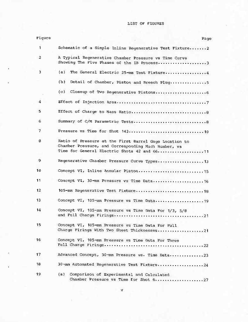
LIST OF FIGURES
Figure Page
1 Schematic of a Simple Inline Regenerative Test Fixture 2
2 A Typical Regenerative Chamber Pressure vs Time Curve Showing The Five Phases of the IB Process 3
3 (a) The General Electric 25-mm Test Fixture 4
(b) Detail of Chamber, Piston and Breech Plug 5
(c) Closeup of Two Regenerative Pistons 6
4 Effect of Injection Area 7
5 Effect of Charge to Mass Ratio 8
6 Summary of C/M Parametric Tests 8
7 Pressure vs Time for Shot 143 10
8 Ratio of Pressure at the First Barrel Gage Location to Chamber Pressure, and Corresponding Mach Number, vs Time for General Electric Shots 42 and 66 11
9 Regenerative Chamber Pressure Curve Types 13
10 Concept VI, Inline Annular Piston 15
11 Concept VI, 30-mm Pressure vs Time Data 16
12 105-mm Regenerative Test Fixture 18
13 Concept VI, 105-mm Pressure vs Time Data 19
14 Concept VI, 105-mm Pressure vs Time Data For 1/3, 5/8 and Full Charge Firings 21
15 Concept VI, 105-inm Pressure vs Time Data For Full Charge Firings With Two Sheet Thicknesses 21
16 Concept VI, 105-inm Pressure vs Time Data For Three Full Charge Firings 22
17 Advanced Concept, 30-mm Pressure vs. Time Data 23
18 30-mm Automated Regenerative Test Fixture 24
19 (a) Comparison of Experimental and Calculated Chamber Pressure vs Time for Shot 6 27
v
(b) Pressure vs Time at Various Positions Calculated Using REGENBAL 28
(c) Pressure vs Time at Various Positions Calculated Using Cough's Code 28
20 Pressure vs Barrel Position at Various Times Calculated with Cough's Code 30
21 (a) Comparison of Experimental and Calculated Chamber Pressure vs Time for Full-Charge 105-mm Test 31
(b) Comparison of Experimental and Calculated Piston Travel vs Time for Full-Charge 105-mm Test 31
VI
I. INTRODUCTION
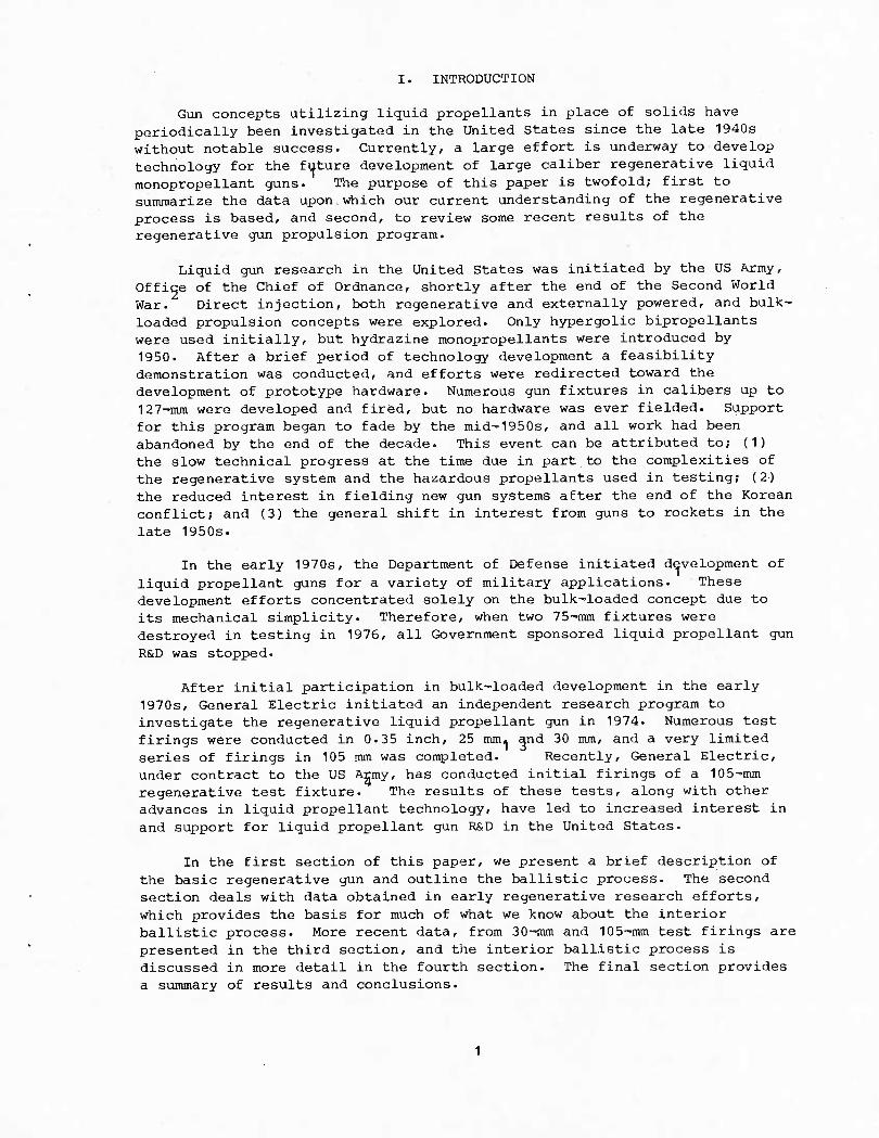
Gun concepts utilizing liquid propellants in place of solids have periodically been investigated in the United States since the late 1940s without notable success. Currently, a large effort is underway to develop technology for the future development of large caliber regenerative liquid monopropellant guns. The purpose of this paper is twofold; first to summarize the data upon which our current understanding of the regenerative process is based, and second, to review some recent results of the regenerative gun propulsion program.
Liquid gun research in the United States was initiated by the US Army, Office of the Chief of Ordnance, shortly after the end of the Second World War. Direct injection, both regenerative and externally powered, and bulk- loaded propulsion concepts were explored. Only hypergolic bipropeHants were used initially, but hydrazine monopropellants were introduced by 1950. After a brief period of technology development a feasibility demonstration was conducted, and efforts were redirected toward the development of prototype hardware. Numerous gun fixtures in calibers up to 127-inm were developed and fired, but no hardware was ever fielded. Support for this program began to fade by the mid-1950s, and all work had been abandoned by the end of the decade. This event can be attributed to; (1) the slow technical progress at the time due in part to the complexities of the regenerative system and the hazardous propellants used in testing; (2) the reduced interest in fielding new gun systems after the end of the Korean conflict; and (3) the general shift in interest from guns to rockets in the late 1950s.
In the early 1970s, the Department of Defense initiated development of liquid propellant guns for a variety of military applications. These development efforts concentrated solely on the bulk-loaded concept due to its mechanical simplicity. Therefore, when two 75-mm fixtures were destroyed in testing in 1976, all Government sponsored liquid propellant gun
R&D was stopped.
After initial participation in bulk-loaded development in the early 1970s, General Electric initiated an independent research program to investigate the regenerative liquid propellant gun in 1974. Numerous test firings were conducted in 0.35 inch, 25 imtu and 30 mm, and a very limited series of firings in 105 mm was completed. Recently, General Electric, under contract to the US Army, has conducted initial firings of a 105-mm regenerative test fixture. The results of these tests, along with other advances in liquid propellant technology, have led to increased interest in and support for liquid propellant gun R&D in the United States.
In the first section of this paper, we present a brief description of the basic regenerative gun and outline the ballistic process. The second section deals with data obtained in early regenerative research efforts, which provides the basis for much of what we know about the interior ballistic process. More recent data, from 30-mm and 105-mm test firings are presented in the third section, and the interior ballistic process is discussed in more detail in the fourth section. The final section provides a summary of results and conclusions.
II. THE BASIC REGENERATIVE PROCESS
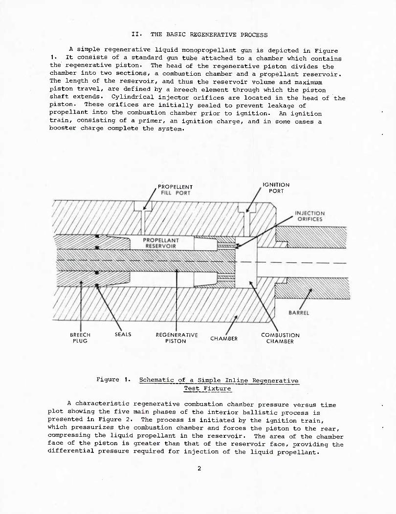
A simple regenerative liquid monopropellant gun is depicted in Figure 1. It consists of a standard gun tube attached to a chamber which contains the regenerative piston. The head of the regenerative piston divides the chamber into two sections, a combustion chamber and a propellant reservoir. The length of the reservoir, and thus the reservoir volume and maximum piston travel, are defined by a breech element through which the piston shaft extends. Cylindrical injector orifices are located in the head of the piston. These orifices are initially sealed to prevent leakage of propellant into the combustion chamber prior to ignition. An ignition train, consisting of a primer, an ignition charge, and in some cases a booster charge complete the system.
PROPELLENT FILL PORT
IGNITION PORT
BREECH PLUG
SEALS REGENERATIVE PISTON CHAMBER COMBUSTION
CHAMBER
Figure 1. Schematic of a Simple Inline Regenerative Test Fixture
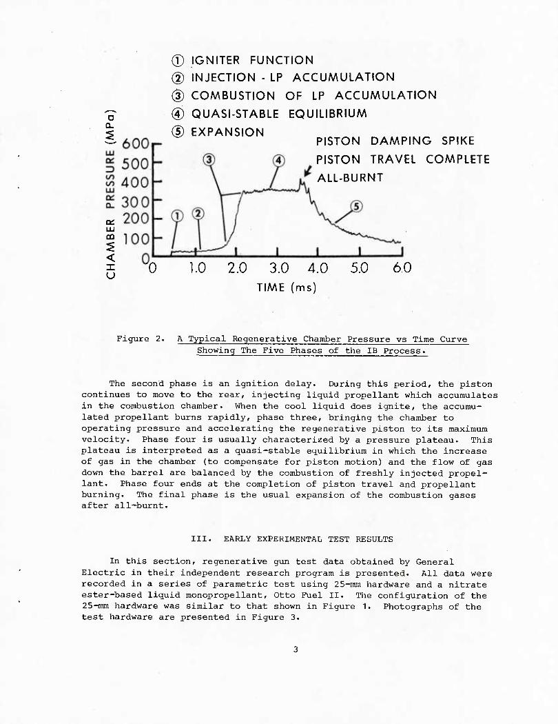
A characteristic regenerative combustion chamber pressure versus time plot showing the five main phases of the interior ballistic process is presented in Figure 2. The process is initiated by the ignition train, which pressurizes the combustion chamber and forces the piston to the rear, compressing the liquid propellant in the reservoir. The area of the chamber face of the piston is greater than that of the reservoir face, providing the differential pressure required for injection of the liquid propellant.
o Q-
LU CO
< X u
® IGNITER FUNCTION
(2) INJECTION - LP ACCUMULATION
(3) COMBUSTION OF LP ACCUMULATION
(4) QUASI-STABLE EQUILIBRIUM
(5) EXPANSION PISTON DAMPING SPIKE
PISTON TRAVEL COMPLETE
ALL-BURNT
'0 1.0 2.0 3.0 4.0 TIME (ms)
5.0 6.0
Figure 2. A Typical Regenerative Chamber Pressure vs Time Curve Showing The Five Phases of the IB Process.
The second phase is an ignition delay. During this period, the piston continues to move to the rear, injecting liquid propellant which accumulates in the combustion chamber. When the cool liquid does ignite, the accumu- lated propellant burns rapidly, phase three, bringing the chamber to operating pressure and accelerating the regenerative piston to its maximum velocity. Phase four is usually characterized by a pressure plateau. This plateau is interpreted as a quasi-stable equilibrium in which the increase of gas in the chamber (to compensate for piston motion) and the flow of gas down the barrel are balanced by the combustion of freshly injected propel- lant. Phase four ends at the completion of piston travel and propellant burning. The final phase is the usual expansion of the combustion gases after all-burnt.
III. EARLY EXPERIMENTAL TEST RESULTS
In this section, regenerative gun test data obtained by General Electric in their independent research program is presented. All data were recorded in a series of parametric test using 25-mm hardware and a nitrate ester-based liquid monopropellant. Otto Fuel II. The configuration of the 25-mm hardware was similar to that shown in Figure 1. Photographs of the test hardware are presented in Figure 3.
h
I LO CM
u •H U u a H W
rt M
a 01 o 0) ja H
0) U 3 60
H a, JS u a) OJ u
OQ
c 3 c o +J
■H
XI
0)
3 & -H
Figure 3. (c) Closeup of Two Regenerative Pistons
Initial test firings demonstrated repeatability in pressure and muzzle velocity comparable to that of conventional solid propellant guns. Subsequent tests were performed to investigate the effects of injection area, injector configuration, charge-to-mass ratio (C/M), and projectile mass, as well as other ballistic parameters.
The effect of total injection area is shown in Figure 4. As the total injection area is increased from 2.03 cm to 3.17 cm (56%), the maximum chamber pressure increases from 186.0 MPa to 338.0 MPa (32.5%) and the muzzle velocity increases from 1043 m/s to 1139 m/s (9.2%). In similar tests at a higher charge to mass ratio, muzzle velocities of 1258 m/s, 1346 m/s, 1417 m/s, and 1468 m/s were obtained for total injection areas of 2.84 cm , 3.85 cm , 4.40 cm , and 5.14 cm . The pressure curves obtained in these tests are similar to those shown in Figure 4.
INJECTION AREA
C/M = 0.6 3.17 cm2
-«/ 2.73 cm2
2.03 cm2
2.0 3.0 4.0 TIME (ms)
Figure 4. Effect of Injection Area
Therefore, the maximum chamber pressure is directly related to the total injection area, which is thus a basic design parameter. In other tests, it was found that with a given total injection area, smaller diameter injectors result in less initial propellant accumulation and less over-shoot in chamber pressure. The length of the injection orifice was also found to affect the ballistic process. Doubling the length of the injector was found to reduce the maximum chamber pressure, and thus reduce the muzzle velocity.
The effect of maximum piston travel, and thus the total charge is shown in Figure 5. In the three tests, only the piston travel was varied. The maximum pressure is approximately the same for each test, however, the length of the plateau region increases with increasing reservoir length. There-fore, the quasi-stable combustion process, once established, is maintained for the duration of piston travel.
The results of tests investigating the influence of C/M and maximum
chamber pressure on muzzle velocity are summarized in Figure 6. The curves of velocity versus C/M for the three chamber pressures are similar in character to those for conventional guns. Figure 6 also serves to summarize the effects of total injection area and piston travel (C/M). For any given C/M, both pressure and velocity increase with increasing injection area, while for any given injection area (maximum pressure), velocity increases with increasing piston travel.
PISTON 300 f C/M = 0.6 ^-^ STROKE 200
/ ^COMPLETE
^ ^ 100 / V o
n 0 300
^t****^ ' '
^-s-*^
•5 —^ C/M=0.7 _^^s
LU 200 - yT \ a: / \ 13 100 — / x^ to J^ ^"VN^^,,^
co 0 ^ i
LU oc 300 ■«■
Q_ C/M = 0.8 v -A 200
/ \
100 " / v_ 0 rT7 1 1 1 1
2.0 3.0
TIME (ms)
Figure 5. Effect of charge to Mass Ratio
_1200 (o
u O _i LU >
1150
1100
FJ1050 N
1000
•^ 303 MPa
x i/ / 255 MPa
/
^—■186 AAPa
0.5 0.6 0.7
c/m
0.8 0.9
Figure 6. Summary of C/M Parametric Tests
The plateau pressure phenomenon was initially attributed to choking of the flow at the entrance to the barrel. However, in computer simulations of test firings, it was necessary to apply a 20-30% correction (reduction) to the barrel flow area in order to match the net gas accumulation in the chamber and the chamber pressure when using the sonic barrel flow assumption. This reduction in effective flow area could be accounted for by a Vena Contracta near the entrance to the bore, which would be favored by the sharp corner at the barrel entrance. However, many of the data obtained in the parametric test firings cannot be reconciled with a theoretical picture which incorporates the hypotheses of a stagnation condition in the chamber and sonic flow in the barrel entrance.
The barrel pressure gage nearest the chamber was mounted 0.7 cm from the bore entrance. The pressure measured at this location in Shot 143, along with the corresponding pressures in the combustion chamber and at other barrel locations are presented in Figure 7. If the flow entering the bore were choked, the ratio of throat pressure to chamber pressure would be about 0.55. The plateau in the chamber pressure occurs at 359 MPa, while the maximum pressure measured by the barrel gage is 324 MPa. Therefore, the ratio of barrel pressure to chamber pressure at the beginning of the plateau is 0.9. This pressure ratio corresponds to a Mach Number of 0.4 at the barrel gage location, well below the choked condition. It is noted that the pressure measured at the barrel wall is not necessarily that in the core flow, and, more importantly, the pressure gage would probably not be located at the minimum area of the vena contracta if one were formed. However, the barrel pressure decreases steadily after the maximum, indicating an increasing Mach Number. This would imply that the flow is not choked at the beginning of the plateau. The Mach Number at the barrel gage location at the end of the plateau is 0.6, still well below the choked condition.
If choked flow at the barrel entrance were responsible for the plateau, choking must be established by the beginning of the flat top. Once choking occurs, the chamber is decoupled from the barrel since information from the bore cannot be propagated upstream through the sonic region. Therefore, the hypothesis of choked flow at the entrance to the bore would require that the chamber pressure be independent of the projectile mass.
As part of the parametric test series, projectile mass was varied to determine its effect on the regenerative process. Two projectile masses were used, 194.4 gm and 97.7 gm. Firings were made with the original chamber, diameter 4.445 cm, and a larger chamber with a diameter of 5.715 cm, see Figure 3. Finally, two firings were made at each condition for a total of 8 tests in this portion of the study. In these tests, the chamber pressure was found to be a function of the projectile mass. With the lighter projectile and the original chamber diameter, the average chamber pressure dropped 24%. In tests with the larger chamber, the average chamber pressure dropped 23% when the lighter projectile was substituted. In both chambers, the muzzle velocity increased by about 11% when the lighter projectile was used.
o
IXI Od
CO to LU cz
500
400
300 -
200 - 100
0
400 3 00
200 100
0
400 -
300
200
100
400
300
200
100 0
400
300
200
100 0
400
300 200
100 0
BARREL PRESSURE
x = 106.7 cm
BARREL PRESSURE
x = 76.2 cm
BARREL PRESSURE
x = 30.5 cm
BARREL PRESSURE
x = 10.2 cm
THROAT PRESSURE
CHAMBER PRESSURE
SHOT 143 C/AA= 1.23
VAA=1475 m/s
2.0 3.0 4.0 5.0
TIME (ms) 6.0
Figure 7. Pressure vs Time for Shot 143.
10
Figure 8 shows the ratio of the pressure at the first barrel gage location to the chamber pressure, along with the corresponding Mach Number, as a function of time for Shot 42 (194.4 gm) and Shot 66 (97.7 gm). The time scale is relative to shot start, and the plateau region is indicated by a dashed line.
0.55
0.60
o 0.70 -
^0.80 LO LU
Q_
0.90 -
1.0
Of UJ
I.U
0.9
0.8
0.7
0.6 i
i
i i
i
PR
ES
SU
RE (
MP
o)
300
200
100
c
/
-- SHOT 42
~\\SHOT66
1 1 1** l
SHOT MB :
66 977gm
A '&
* *
A -^ ' A
y
z X
1.0 2.0 3.0 TIME (ms)
4.0 ,/o
SHOT 42
MB = 194.4 gm LU rv
0.5 - Jf
< CD
0.4
0.3 0.2
A
1- 1 o A,
O
i. .
o
1 1 1 1 ! 1
0.2 0.4 0.6 0.8 1.0 1.2 TIME AFTER SHOT START (ms)
2.0
Figure 8. Ratio of Pressure at the First Barrel Gage Location to Chamber Pressure, and corresponding Mach Number,
vs Time for General Electric Shots 42 and 66.
The insert shows the pressure curves for these firings. As in Shot 143, Figure 7, the Mach Number at the barrel gage location increases steadily after the plateau is reached. Note, however, that the Mach Number is significantly higher in the case of the light projectile. In both cases the Mach Number approaches unity by the end of the plateau, indicating a tendency toward choking near the end of the plabeau region. This tendency could be increased in high velocity firings with large charges and light projectiles. However, choking of the entrance flow to the barrel would not appear to influence the establishment of the pressure plateau.
Examination of the barrel entrance Mach Number and the effects of projectile mass would appear to eliminate choked flow as the cause of the pressure plateau in regenerative gun firings. In order to explain the plateau, we consider the relative mass flow rate of an ideal gas through a constriction as a function of Mach Number. At a Mach Number of 0.5 the relative mass flow rate is 0.75, and at a Mach Number of 0.7 the relative mass flow rate is about 0.91. The mass flow rate is a very weak function of Mach Number, and thus the pressure ratio, for Mach Numbers above 0.5. While the weak dependence of mass flow rate on Mach Number, and thus pressure ratio, would indicate a tendency toward a pressure plateau, it cannot explain the extreme flatness of the regenerative pressure curves.
1 1
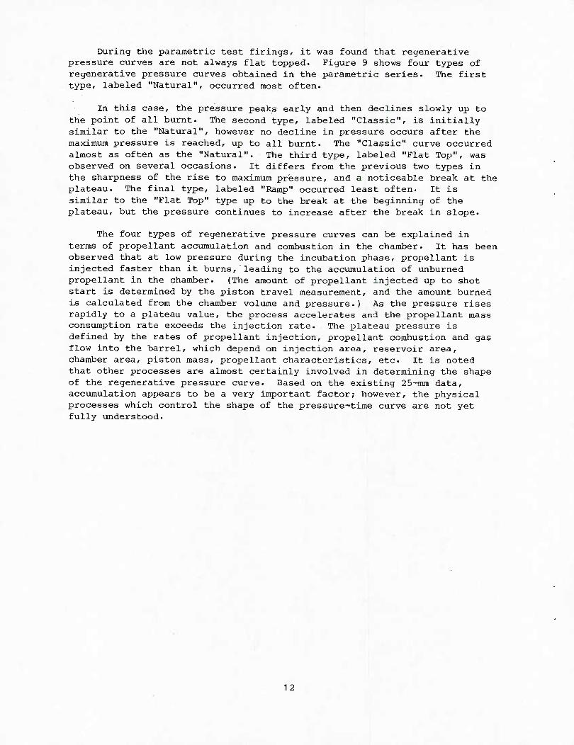
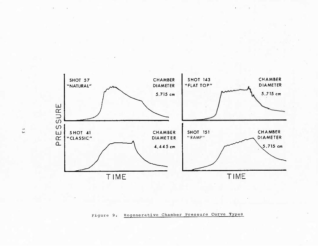
During the parametric test firings, it was found that regenerative pressure curves are not always flat topped. Figure 9 shows four types of regenerative pressure curves obtained in the parametric series. The first type, labeled "Natural", occurred most often.
In this case, the pressure peaks early and then declines slowly up to the point of all burnt. The second type, labeled "Classic", is initially similar to the "Natural", however no decline in pressure occurs after the maximum pressure is reached, up to all burnt. The "Classic" curve occurred almost as often as the "Natural". The third type, labeled "Flat Top", was observed on several occasions. It differs from the previous two types in the sharpness of the rise to maximum pressure, and a noticeable break at the plateau. The final type, labeled "Ramp" occurred least often. It is similar to the "Flat Top" type up to the break at the beginning of the plateau, but the pressure continues to increase after the break in slope.
The four types of regenerative pressure curves can be explained in terms of propellant accumulation and combustion in the chamber. It has been observed that at low pressure during the incubation phase, propellant is injected faster than it burns, leading to the accumulation of unburned propellant in the chamber. (The amount of propellant injected up to shot start is determined by the piston travel measurement, and the amount burned is calculated from the chamber volume and pressure.) As the pressure rises rapidly to a plateau value, the process accelerates and the propellant mass consumption rate exceeds the injection rate. The plateau pressure is defined by the rates of propellant injection, propellant combustion and gas flow into the barrel, which depend on injection area, reservoir area, chamber area, piston mass, propellant characteristics, etc It is noted that other processes are almost certainly involved in determining the shape of the regenerative pressure curve. Based on the existing 25-mm data, accumulation appears to be a very important factor; however, the physical processes which control the shape of the pressure-time curve are not yet fully understood.
12
LU cr ZD <J) CO LU cr Q_
SHOT 5 7 'NATURAL"
SHOT 41 'CLASSIC"
TIME
CHAMBER DIAMETER
5.715 cm
CHAMBER DIAMETER
4.445 cm
SHOT 143 FLAT TOP'
SHOT 151 "RAMP"
TIME
CHAMBER DIAMETER
5.715 cm
CHAMBER DIAMETER
.5.715 cm
Figure 9. Regenerative Chamber Pressure Curve Types
IV. RECENT EXPERIMENTAL TEST RESULTS
In this section, we present a summary of data from recent regenerative test firings. While the work reported in the previous section was conducted to investigate the regenerative ballistic process, recent efforts have focused on the development of advanced concepts, and scaling to large caliber fixtures.
A practical mechanization of the regenerative process must meet several requirements. There must be a convenient means for projectile loading, and for achieving a rapid, ullage free propellant fill. For application in an artillery role, zoning to provide the necessary range coverage, and the ability to tailor interior ballistics (in order to launch munitions of widely varying mass and acceleration sensitivity) are required. A critical aspect of all these issues is the development of seals, with adequate lifetime and durability, for use at a number of internal locations.
The simple mechanization shown in Figure 1 proved to be an ideal test vehicle for studying the regenerative process. Modifications could be made quickly and cheaply, and the simplicity of a single moving element, together with constant propellant injection area, greatly simplified analysis of experimental data. However, this configuration did not appear to be suitable for practical applications. It is difficult to seal the injector orifices during propellant fill, and there is no means of programming the propellant injection area. The first problem makes it difficult to achieve rapid, ullage-free fill. The latter problem makes it difficult to tailor the interior ballistics to accommodate different payloads.
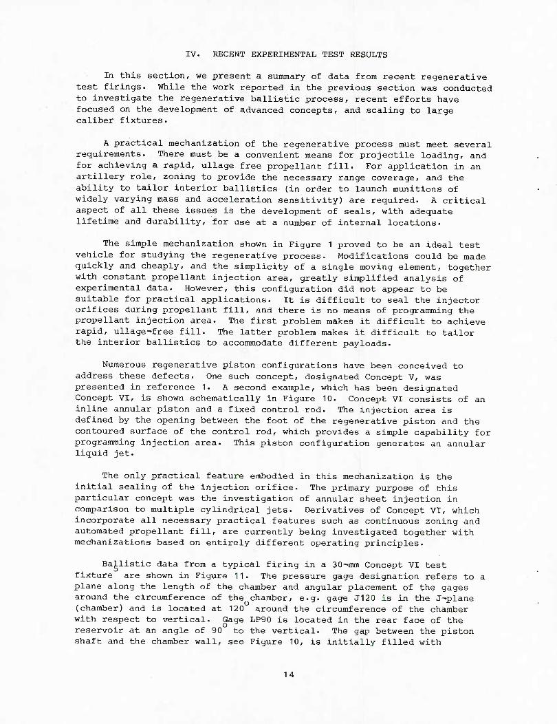
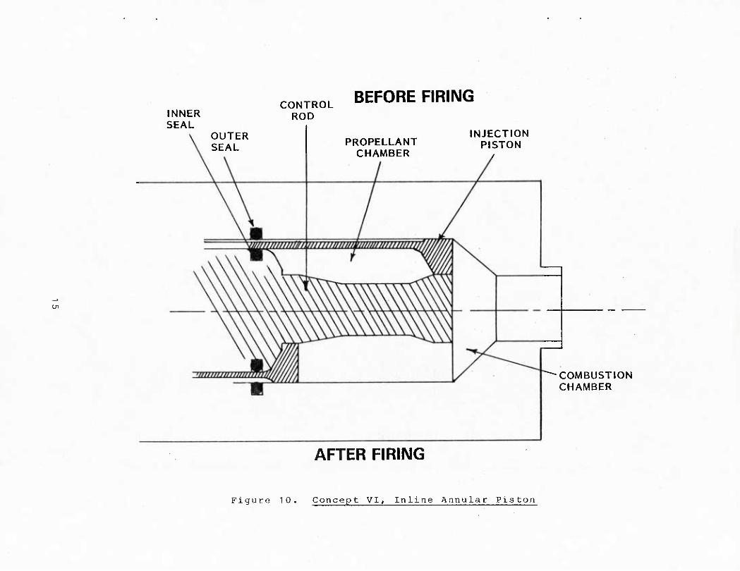
Numerous regenerative piston configurations have been conceived to address these defects. One such concept, designated Concept V, was presented in reference 1. A second example, which has been designated Concept VI, is shown schematically in Figure 10. Concept VI consists of an inline annular piston and a fixed control rod. The injection area is defined by the opening between the foot of the regenerative piston and the contoured surface of the control rod, which provides a simple capability for programming injection area. This piston configuration generates an annular liquid jet.
The only practical feature embodied in this mechanization is the initial sealing of the injection orifice. The primary purpose of this particular concept was the investigation of annular sheet injection in comparison to multiple cylindrical jets. Derivatives of Concept VI, which incorporate all necessary practical features such as continuous zoning and automated propellant fill, are currently being investigated together with mechanizations based on entirely different operating principles.
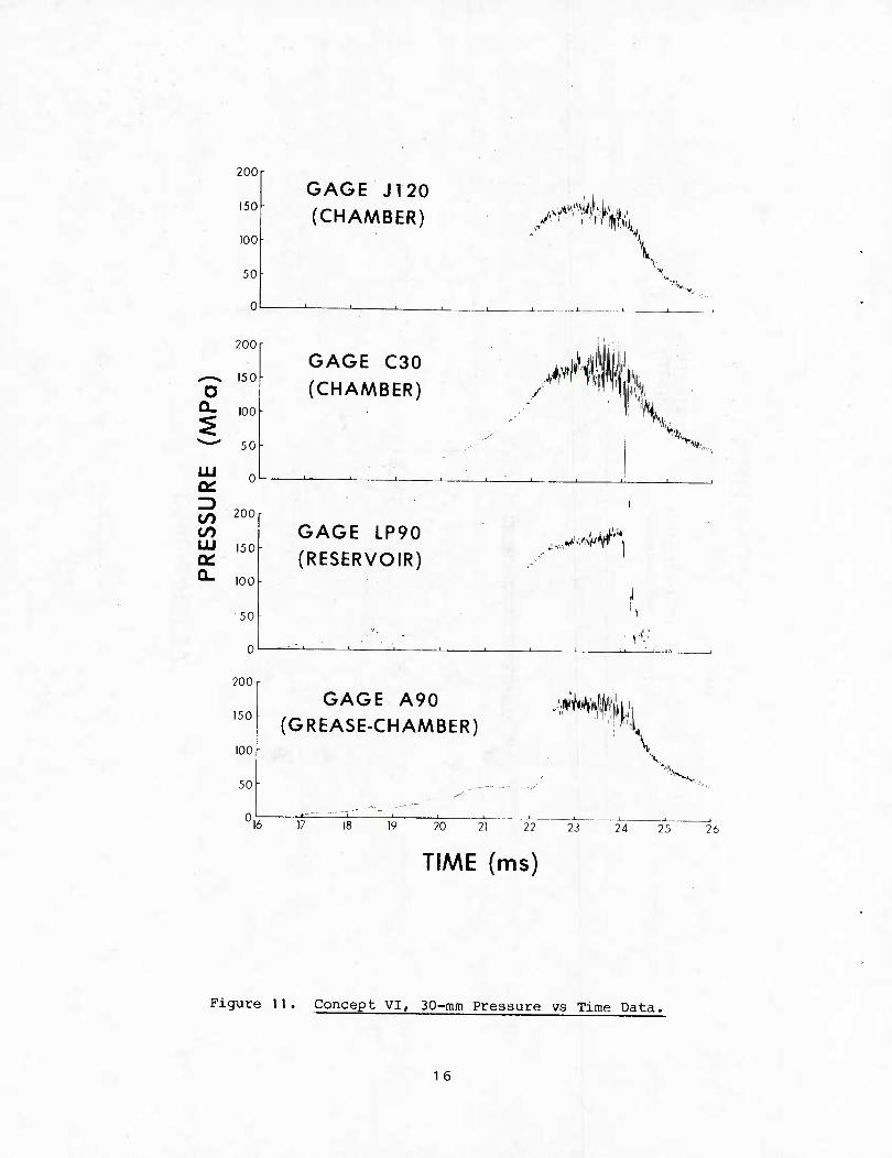
Ballistic data from a typical firing in a 30-mm Concept VI test fixture are shown in Figure 11. The pressure gage designation refers to a plane along the length of the chamber and angular placement of the gages around the circumference of the chamber, e.g. gage J120 is in the J-plane (chamber) and is located at 120 around the circumference of the chamber with respect to vertical. Gage LP90 is located in the rear face of the reservoir at an angle of 90 to the vertical. The gap between the piston shaft and the chamber wall, see Figure 10, is initially filled with
14
INNER SEAL
CONTROL ROD
BEFORE FIRING
OUTER SEAL PROPELLANT
CHAMBER
INJECTION PISTON
AFTER FIRING
COMBUSTION CHAMBER
Figure 10. Concept VI, Inline Annular Piston
200
150
100
50
0
O
CO CO LU
a.
200
150
100
50
0
200
150
100
50
0
200
150
100
50[-
0
GAGE Jr20 (CHAMBER)
GAGE C30
(CHAMBER)
GAGE LP90 (RESERVOIR)
GAGE A90 (GREASE-CHAMBER)
^fm Pi
M /
mm \ V
i',*„
..^M;\
J;f^H4 iTi L
16 17 19 20 21 22 73
TIME (ms)
24 26
Figure 11. Concept VI, 30-mm Pressure vs Time Data.
1 6
grease. Gage A.90 initially reads grease pressure, but transitions to chamber pressure as the piston moves to the rear. The propellant used was LGP 1846, an hydroxylammonium nitrate-based liquid monopropellant. The high frequency oscillations in all the pressure data are characteristic of Concept VI, and have been observed in 25-11101 and 105-mm test data as well. The source of these oscillations has been the subject of much discussion and analysis. It was initially suggested that the oscillations were the result of,an acoustic instability in the combustion chamber, similar to that observed by Hassenbein in a simple 40-mm regenerative fixture. However, the complex structure of the oscillations is not characteristic of an acoustic instability. Other possible sources for the oscillations are the response of the pressure gages to stress waves in the tube and chamber, mechanical vibration of the regenerative piston, and a hydrodynamic instability in the injection orifice. The source of the oscillations has not been determined. However, the oscillations have not adversely affected the ballistic process in any test fixture, and, as will be discussed below, oscillations have not been observed in the derivatives of Concept VI.
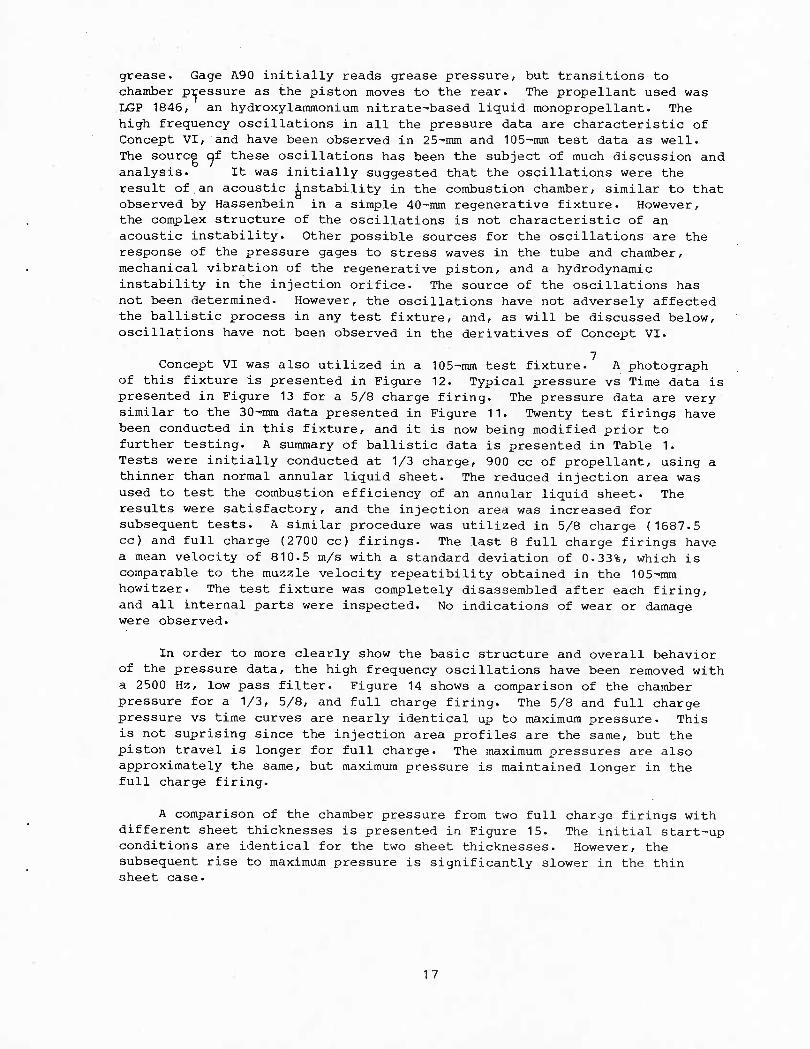
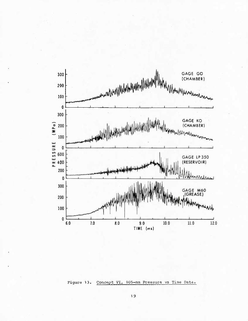
7 Concept VI was also utilized in a 105-mm test fixture. A photograph
of this fixture is presented in Figure 12. Typical pressure vs Time data is presented in Figure 13 for a 5/8 charge firing. The pressure data are very similar to the 30-mm data presented in Figure 11. Twenty test firings have been conducted in this fixture, and it is now being modified prior to further testing. A summary of ballistic data is presented in Table 1. Tests were initially conducted at 1/3 charge, 900 cc of propellant, using a thinner than normal annular liquid sheet. The reduced injection area was used to test the combustion efficiency of an annular liquid sheet. The results were satisfactory, and the injection area was increased for subsequent tests. A similar procedure was utilized in 5/8 charge (1687.5 cc) and full charge (2700 cc) firings. The last 8 full charge firings have a mean velocity of 810.5 m/s with a standard deviation of 0.33%, which is comparable to the muzzle velocity repeatibility obtained in the 105-mm howitzer. The test fixture was completely disassembled after each firing, and all internal parts were inspected. No indications of wear or damage were observed.
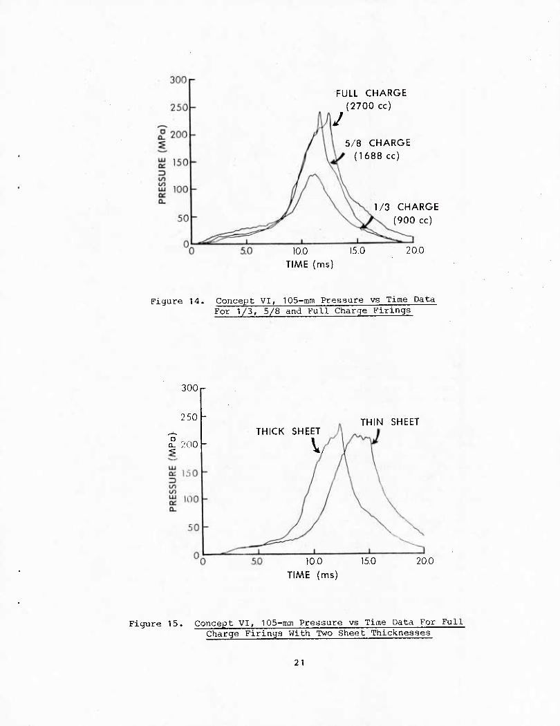
In order to more clearly show the basic structure and overall behavior of the pressure data, the high frequency oscillations have been removed with a 2500 Hz, low pass filter. Figure 14 shows a comparison of the chamber pressure for a 1/3, 5/8, and full charge firing. The 5/8 and full charge pressure vs time curves are nearly identical up to maximum pressure. This is not suprising since the injection area profiles are the same, but the piston travel is longer for full charge. The maximum pressures are also approximately the same, but maximum pressure is maintained longer in the full charge firing.
A comparison of the chamber pressure from two full charge firings with different sheet thicknesses is presented in Figure 15. The initial start-up conditions are identical for the two sheet thicknesses. However, the subsequent rise to maximum pressure is significantly slower in the thin sheet case.
17
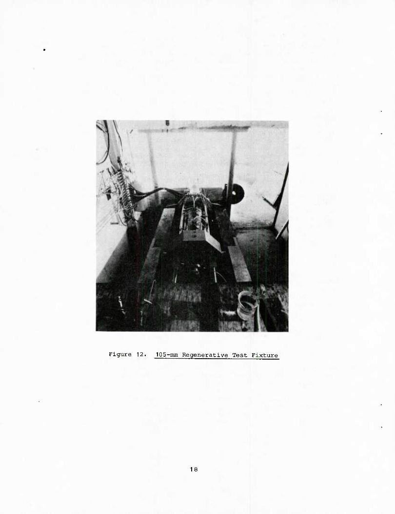
Figure 12. 105-mm Regenerative Test Fixture
18
300 -
200 -
100
GAGE GO (CHAMBER)
GAGE KG CHAMBER)
8.0 9.0 TIME (mi)
Figure 13. Concept VI, 105-mm Pressure vs Time Data.
1 9
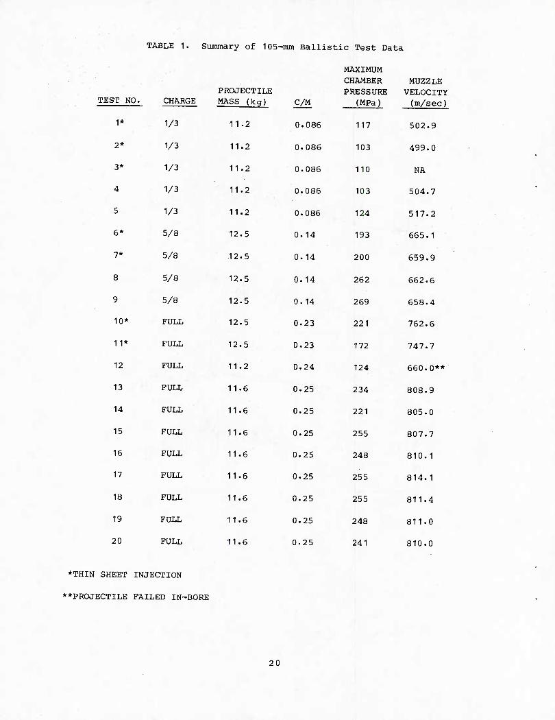
TABLE 1. Summary of 105-inm Ballistic Test Data
MAXIMUM CHAMBER MUZZLE
TEST NO. CHARGE PROJECTILI MASS (kg)
1* 1/3 11.2
2* 1/3 11.2
3* 1/3 11.2
4 1/3 11.2
5 1/3 11.2
6* 5/8 12.5
7* 5/8 .12.5
8 5/8 12.5
9 5/8 12.5
10* FULL 12.5
11* FULL 12.5
12 FULL 11.2
13 FULL 11.6
14 FULL 11.6
15 FULL 11.6
16 FULL 11.6
17 FULL 11.6
18 FULL 11.6
19 FULL 11.6
20 FULL 11.6
C/M
0.086
0.086
0.086
0.086
0.086
0. 14
0.14
0.14
0. 14
0.23
0.23
0.24
0.25
0.25
0.25
0.25
0.25
0.25
0.25
0.25
PRESSURE VELOCITY (MPa) (m/sec)
117
103
110
103
124
193
200
262
269
221
172
124
234
221
255
248
255
255
248
241
502.9
499.0
NA
504.7
517.2
665.1
659.9
662.6
658.4
762.6
747.7
660.0**
808.9
805.0
807.7
810.1
814.1
811.4
811.0
810.0
*THIN SHEET INJECTION
**PROJECTILE FAILED IN-BORE
20
FULL CHARGE (2700 cc)
J 5/8 CHARGE
(1688 cc)
10.0 TIME (ms)
1/3 CHARGE (900 cc)
20,0
Figure 14. Concept VI, 105-mm Pressure vs Time Data For 1/3, 5/8 and Full Charge Firings
300 r
250
(S 200 THICK SHEET
V,
100 TIME (ms)
THIN SHEET
20.0
Figure 15. Concept VI, lOS-mm Pressure vs Time Data For Full Charge Firings With Two Sheet Thicknesses
21
300r
50 1.0 TIME (ms)
15.0 20.0
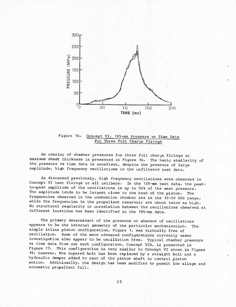
Figure 16. Concept VI, lOS-rnm Pressure vs Time Data For Three Full Charge Firings
An overlay of chamber pressures for three full charge firings at maximum sheet thickness is presented in Figure 16. The basic similarity of the pressure vs time data is excellent, despite the presence of large amplitude, high frequency oscillations in the unfiltered test data.
As discussed previously, high frequency oscillations were observed in Concept VI test firings in all calibers. In the 105-mm test data, the peak- to-peak amplitude of the oscillations is up to 50% of the mean pressure. The amplitude tends to be largest close to the head of the piston. The frequencies observed in the combustion chamber are in the 10-50 kHz range, while the frequencies in the propellant reservoir are about twice as high. No structural regularity or correlation between the oscillations observed at different locations has been identified in the 105-mm data.
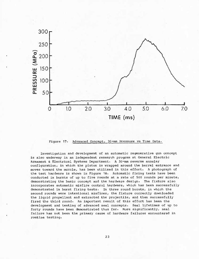
The primary determinant of the presence or absence of oscillations appears to be the internal geometry of the particular mechanization. The simple inline piston configuration. Figure 1, was virtually free of oscillation. Some of the more advanced configurations currently under investigation also appear to be oscillation free. Typical chamber pressure vs time data from one such configuration. Concept VIA, is presented in Figure 17. This configuration is very similar to Concept VI shown in Figure 10; however, the tapered bolt has been replaced by a straight bolt and a hydraulic damper added to rear of the piston shaft to control piston motion. Additionally, the design has been modified to permit low ullage and automatic propellant fill.
22
300 r
3.0 4.0
TIME (ms)
70
Figure 17. Advanced Concept, .30-mm Pressure vs Time Data.
Investigation and development of an automatic regenerative gun concept is also underway in an independent research program at General Electric Armament & Electrical Systems Department. A 30-mm reverse annular configuration, in which the piston is wrapped around the barrel entrance and moves toward the muzzle, has been utilized in this effort. A photograph of the test hardware is shown in Figure 18. Automatic firing tests have been conducted in bursts of up to five rounds at a rate of 500 rounds per minute, demonstrating the basic concept and the hardware design. The fixture also incorporates automatic misfire control hardware, which has been successfully demonstrated in burst firing tests. In three round bursts, in which the second rounds were intentional misfires, the fixture correctly downloaded the liquid propellant and extracted the projectile, and then successfully fired the third round. An important result of this effort has been the development and testing of advanced seal concepts. Seal lifetimes of up to forty rounds have been demonstrated thus far. More significantly, seal failure has not been the primary cause of hardware failures encountered in routine testing.
23
Figure 18. 30-inm Automated Regenerative Test Fixture
24
V. INTERIOR BALLISTIC SIMULATIONS
In this section we discuss certain aspects of the interior ballistic process in the regenerative liquid propellant gun. A general discussion of the interior ballistics of the regenerative guns has been presented by a number of authors and will not be repeated here. Our principal emphasis will be the combustion model, but we will also discuss barrel flow and pressure gradients in the barrel. Additionally we present a comparison of model predictions and experimental results.
As mentioned earlier, piston motion compresses the liquid propellant, injecting it through orifices into the combustion chamber as a jet. The breakup of the liquid jet into droplets and subsequent combustion of these droplets in the chamber and barrel are not well understood. It has been suggested that the accumulation of unburnt liquid droplets in the chamber and barrel has a significant influence on the ballistic cycle, and that the basic shapes of the pressure"time curves can be explained in terms of accumulation.
At low pressure, propellant is injected more rapidly than it is consumed, and, therefore, accumulates in the chamber. It is probable that the jet will impact the forward end of the chamber and the projectile base, enhancing breakup. Based on this scenario, substantial propellant combustion would be expected to occur near the projectile base, during early projectile motion.
However, later in the cycle, the increased chamber pressure, and piston and projectile motion would modify this picture. First, the rate of jet breakup and propellant combustion are expected to increase with increasing pressure. Second, as the piston moves toward the breech, the distance which the liquid must travel to reach the barrel entrance increases. The jet velocity also increases, but this would tend to enhance jet breakup, and, therefore, combustion. Thus, it can be argued that the portion of propellant burned in the chamber increases daring the ballistic cycle, that the amount of propellant burned in the barrel decreases, and that little or no propellant combustion takes place near the base of the projectile during much of projectile travel.
We can distinguish two major classes of combustion models used in interior ballistic codes. In the simpler case, it is assumed that combustion occurs instantaneously upon injection of the liquid propellant into the chamber. In the other case, it is assumed that the liquid jet is atomized as it enters the chamber. The resulting droplets may either ignite and burn, or undergo further breakup before combustion occurs. The literature contains numerous studies addressing jet breakup and droplet spray formation for both combusting and .non-'combusting liquids. Much of this work has been summarized by Faeth and Harrje. The majority of these studies deal with injection and spray formation either in liquid propellant rockets or internal combustion engines and, therefore, the resulting models, correlations, etc. are not necessarily applicable over most of the gun ballistic cycle. Such models could be applied during the ignition and initial injection phase, when the chamber pressure is low. However, existing data indicates that the liquid jet probably impacts the forward end of the chamber, particularly at low pressure early in the
25
cycle. In this case, jet breakup is due to spall which is not treated in the usual spray models. Therefore, the use of existing breakup models cannot be rigorously justified in the case of the regenerative gun. At best, such models provide adjustable parameters in the form of a time lag for droplet formation and an initial droplet size, or droplet size distribution. The simplest description of the breakup phenomena is the Weber Number correlation, from which a stable, initial droplet size is obtained.
Heating, igt^t^n and combustion of monopropellant droplets have been treated by Faeth in some detail. However, in view of the uncertainty in the initial droplet size, a rigorous treatment of droplet ignition and combustion is not warranted. Droplet combustion in most models is treated by defining a linear regression rate which is proportional to the local pressure raised to a power, as in the case of solid propellant combustion.
The flow in the barrel consists of burning liquid droplets mixed with combustion gases. Most regenerative ballistic models assume that burning occurs in the combustion chamber only. This is in contrast to the solid propellant gun models which assume a distribution of burning solid propellant grains between the breech end of the chamber and the base of the projectile. If the flow in the barrel can be assumed to be single phase, consisting only of combustion gases, then the pressure gradient in the barrel can be described by standard interior ballistic approximations. The alternative is the numerical solution to the one-dimensional mass and momentum conservation equations in the barrel.
The standard solid propellant gun interior ballistic approximations for the pressure gradient (Lagrange, Pidduck-Kent, etc) are developed with the assumptions that all the propellant charge is in gaseous form at the time considered and that the gas velocity at the breech is zero. These approximations have been routinely applied to gun interior ballistic problems in which solid propellant burns during most of the projectile travel. For regenerative ballistic models these approximations must be modified to account for a non-zero mass flow rate at the barrel .entrance. These modified equations have been presented by Morrison et al. Pagan et al and by Smith and Dorsey.18
A comparison of experimental data and two computer simulations are presented in Figure 19 for Shot 6 of the first General Electric, 25-mm gun test series. Interior ballistic models developed by Gough and Bulman were used in the simulations. Both models treat the combustion chamber as two- phase, lumped parameter region while a 1-D formulation is used in the barrel. In Bulman's code, REGENBAL, droplet burning is confined to the chamber, while the Gough model permits droplets to burn both in the chamber and in the barrel. Bulman utilizes the Weber number criteria to determine the size of droplets resulting from liquid jet breakup at any given time, resulting in a size distribution of burning droplets in the chamber. Gough permits only one size of droplets to exist in any one simulation. (A more detailed combustion model is currently being developed.) This code also permits the assumption of an infinite liquid consumption rate, i.e. the propellant burns immediately as it enters the combustion chamber. This option was selected for the simulation presented here. The only "adjustable parameter" used in the simulation is the discharge coefficient for the
26
injection orifices, which was varied to match the maximum pressure obtained
in the experimental firing, 255 MPa. With a discharge coefficient of 0.58, a computed maximum pressure of 262.4 MPa was obtained with the Gough code and 257.6 MPa with REGENBAL. The experimental muzzle velocity was 1106 m/s, while the computed muzzle velocity was 1107 m/s with the Gough code and 1106 m/s with REGENBAL.
The experimental curve in Figure 19a is of the "Classic" variety, with a smooth transition to the plateau. The calculated curve from the Gough code is a "Natural" with a steadily decreasing pressure after the plateau is reached. This calculated result is consistent with the choice of the infinite burn rate option, since the possibility of accumulation of liquid droplets is eliminated. The curve calculated with REGENBAL is also a "Natural", but the rise in pressure and the plateau region closely match the experimental curve. Only in the region close to burnout and during the expansion phase do the model results diverge from the experimental result.
300r
2.0
TIME (ms)
Figure 19. (a) Comparison of Experimental and Calculated Chamber Pressure vs Time for Shot 6.
Figures 19b and 19c show the computed pressure-time curves at various locations in the gun obtained with the Bulman and Gough codes respectively. The Bulman model predicts an oscillatory pressure in the combustion chamber and at the base of the projectile shortly after the start of projectile motion. The origin of these oscillations has not been fully determined, but it is believed to be related to shot start. The pressure in the liquid reservoir, the combustion chamber, the barrel entrance, and at the projectile base, obtained using the Gough code, are presented in Figure 19c. In both simulations, peak pressure at the base of the projectile occurs earlier in time than does peak pressure in the combustion chamber or the liquid reservoir, reflecting time lag between events at projectile base and events in the combustion chamber due to a finite sound velocity.
27
05 1.0 15 2.0 25 TIME (ms)
3.0 J 3.5
Figure 19. (b) Pressure vs Time at Various Positions Calculated Using REGENBAL.
05 1.0 1.5 2.0 2.5
TIME (ms) 30 3.5
Figure 19. (c) Pressure vs Time at Various Positions Calculated Using Cough's Code
28
Figure 20 shows gas pressure versus position in the barrel at four times during the ballistic cycle for Shot 6, computed using Cough's code. The first curve shows the pressure profile in the barrel just before propellant burnout, 2.5 ms. The three subsequent profiles illustrate the drop in pressure at barrel entrance caused by burnout, and the propagation of the resulting rarefaction wave down the barrel toward the base of the projectile. In this case, the rarefaction wave does not reach the base of the projectile before muzzle exit. Therefore, the projectile does not "know" that burnout had occurred, and the muzzle velocity was not influenced by all-burnt. These curves illustrate communication of events occurring in the combustion chamber by either compression or expansion pressure waves to the base of the projectile at the local velocity of sound in the barrel.
A similar comparison between experiment and simulation is presented in Figure 21. The experimental results are from a full-charge 105-mm regenerative te|t firing. An engineering model developed for hardware design studies was used in this simulation. This code incorporates jet breakup and droplet combustion models which have been calibrated through comparisons with experimental gun data. The experimental and simulated pressure curves are grossly similar, but the shortcomings of the model are apparent in the ignition and plateau regions. The agreement between the experimental and simulated piston travel is much better, indicating that the details of the pressure curve do not significantly influence the motion of the regenerative piston. While this type of code does not contribute to a detailed understanding of the interior ballistic process, it has proven valuable in the design of several regenerative text fixtures.
The description of the combustion process, where and how the propellant burns, is the most significant shortcoming in current regenerative interior ballistic simulations. The effects should be most evident during the low pressure ignition phase when propellant is expected to accumulate in the combustion chamber. However, as noted, the overall shape of the pressure- time curve is also affected. Detailed experimental investigation of the jet breakup and combustion processes is required for the development of improved interior ballistic simulations.
VI. SUMMARY
Experimental test firings of regenerative liquid monopropellant guns have been conducted in a variety of mechanizations ranging from 0.35 inch to 105-mm. The 25-mm parametric tests conducted by General Electric in the mid-1970s helped to elucidate the fundamental characteristics of the regenerative process. The influence of injection area, charge length, charge to mass ratio, maximum pressure and projectile mass were demonstrated. More recently, efforts have focused on the development of practical mechanizations of the regenerative concept. A fully automatic regenerative fixture has been developed and tested at 500 rounds per minute in bursts of limited duration. Scaling of the concept to 105-mm has also been successfully demonstrated. Several interior ballistic simulations of the regenerative process have been developed. These models describe the basic process, and accurately reproduce the experimental maximum pressure and muzzle velocity. However, they do not adequately treat the details of the combustion process. Detailed experimental investigations are required in support of the development of improved interior ballistic simulations.
29
MOr
o
CO CO LU a: Q-
(MUZZLE EXIT)
J I L. 0.5 1.0 1.5 2.0
PROJECTILE TRAVEL (m) 2.5
Figure 20. Pressure vs Barrel Position at Various Times Calculated with Gough's Code.
30
300r
o Q_
250 ^ 200 UJ (X. 150 J^J <S) CO LU 100 OH Q- 50
0
COMPUTER SIMULATION
EXPERIMENT
0 5.0 100 15.0 20.0 25.0 30.0
TIME (ms)
Figure 21. (a) Comparison of Experimental and Calculated Chamber Pressure vs Time for Full-Charge 105-mm Test.
25.0 - COMPUTER SIMULATION
— EXPERIMENT
0 5.0 10.0 15.0 20.0
TIME (ms)
25.0 30.0
Figure 21. (b) Comparison of Experimental and Calculated Piston Trave1 vs Time for Full-Charge 105-mm Test.
3 1
VII. FUTURE EFFORTS
Liquid propellant gun technology is being aggressively pursued in the United States. Future efforts will address the development of improved mechanizations and component technologies, a more detailed understanding of the regenerative process, and a further scaling demonstration. Gun firing investigations in 30-mm and 105-mm caliber will continue. However, specially designed ignition and combustion test fixtures are being developed to study the regenerative combustion process in more detail. Advanced, large caliber regenerative mechanizations, capable of automatic operation, are under development. Significant effort will center on the development of seal technology and the evaluation of new seal concepts. The focus of these efforts is the development and testing of a 155-mm, technology demonstration fixture.
32

REFERENCES
1. Morrison, W.F., Knapton, J.D., and Klingenberg, G., "Liquid Propellants For Gun Applications," Proceedings of the Seventh International Ballistics Symposium, 1983.
2. Hudson, CM., "Army Ordnance L. P. G. Program," Proceedings of the Third Annual Conference on Liquid Propellant Guns, 1952.
3. Graham, A. and Bulman, M.J., "General Electric 25-mm Regenerative Liquid Propellant Gun Program," Proceedings of the Twelfth JANNAF Combustion Meeting, 1975.
4. Morrison, W.F., Bulman, M.J., Baer, P.G., and Banz, C.F., "The Interior Ballistics of Regenerative Liquid Propellant Guns," Proceedings of the 1984 JANNAF Propulsion Meeting.
5. Watson, C. and Knapton, J.D., US Army Ballistic Research Laboratory, Private Communication.
5. Baer, P.G. and Morrison, W.F., "Modeling of High Frequency Pressure Oscillations in 105-mm Regenerative Liquid Propellant Gun," Proceedings of the Twentieth JANNAF Combustion Meeting, 1983.
7. Mandzy, J., Magoon, I., Morrison, W.F., and Knapton, J.D., "Preliminary Report on Test Firings of a lOS-mm Regenerative Fixture," Proceedings of the Twentieth JANNAF Combustion Meeting, 1983.
8. Hassenbein, R. , "Regenerative Liquid Propellant Gun Technology," USALCWSL Report ARLCB-TR-81026, June 1981.
9. Graham, A., "The Super Pressure Combustor: A Ballistic Simulator," Proceedings of the Thirteenth JANNAF Combustion Meeting, 1976.
10. Graham, A., "A Closed Form Theory for the Regenerative Liquid Propellant Gun," Proceedings of the Twentieth JANNAF Combustion Meeting, 1983.
11. Carayol, N., "Sur Une Famille De Solutions Exactes Du Probleme De La Balistique Interieure Avec Injection D'Ergols," Sciences Et Techniques De L'Armement, 53, ler FASC, 1979.
12. Pagan, G., Harvey, A., and Izod, D.C.A., "Regenerative Liquid Propellant Gun Modeling," Proceedings of the Seventh International Symposium on Ballistics, 1983.
13. Gough, P.S., "A Model of the Interior Ballistics of Hybrid Liquid Propellant Guns," US Army Ballistic Research Laboratory Contract Report, BRL-CR-'566, March 1987.
14. Faeth, G.M., "Current Status of Droplet and Liquid Combustion," Prog. Energy Combust. Sci., Vol. 3, 1977.
33

15.
16.
17.
18.
19.
Harrje, D.T. and Reardon, F.H., eds., "Liquid Propellant Rocket Combustion Instability," NASA SP-194, 1972.
Devine, M. and Brodman, B., "Neutron Radiographic Studies of Liquid Propellant Combustion," Proceedings of the Twentieth JANNAF Combustion Meeting, 1983.
Faeth, G.M., Karhan, B.L., and Yanyecic, G.A., "Ignition and Combustion of Monopropellant Droplets," AIAA Journal, Vol. 6, No. 4, April, 1968.
Smith, E.H. and Dorsey, E.G., "Liquid Fuel Catapults With Regenerative Injection VI: Interior Ballistics, A Theory of Pressure Variation During Burning of the Propellant," Experiment, Inc. TP No. 62, Contract No. DA-36-034-ORD-763RD, 1953.
Cushman, P., General Electric Ordnance Systems Division, Private Communication.
3 4
No. of Copies
12
Organization
DISTRIBUTION LIST
No. of Copies
13
Commander Defense Technical Info Center ATTN: DTIC-DDA Cameron Station Alexandria, VA 22304-6145
Director Defense Advanced Research
Projects Agency ATTN: H. Fair 1400 Wilson Boulevard Arlington, VA 22209
HQDA DAMA-ART-M Washington, DC 20310
Commander US Army Materiel Command ATTN: AMCDRA-ST 5001 Eisenhower Avenue Alexandria, VA 22333-0001
Commander Armament R&D Center US Army AMCCOM ATTN: SMCAR-TSS
SMCAR-TDC SMCAR-SCA, B. Brodman
R. Yalamanchili SMCAR-AEE-B, D. Downs
A. Beardell SMCAR-LCE, N. Slagg SMCAR-LCS, W. Quine
A. Bracuti J. Lannon
SMCAR-FSS-A, R. Price L. Frauen
SMCAR-FSA-S, H. Liberman Picatinny Arsenal, NJ 07805-5000
Organization
Director
Benet Weapons Laboratory Armament R&D Center US Army AMCCOM ATTN: SMCAR-LCB-TL
E. Conroy A. Graham
Watervliet, NY 12189
Commander US Army Armament,. Munitions
and Chemical Command ATTN: SMCAR-ESP-L Rock. Island, IL 61299-7300
Commander US Army Aviation Research
and Development Command ATTN: AMSAV-E 4300 Goodfellow Blvd. St. Louis, MO 63120
Commander Materials Technology Lab US Army Laboratory Cmd ATTN: SLCMT-MCM-SB
M. Levy Watertown, MA 02172-0001
Director US Army Air Mobility Rsch.
and Development Lab. Ames Research Center Moffett Field, CA 94035
Commander US Army Communications
Electronics Command ATTN: AMSEL-ED Fort Monmouth, NJ 07703
Commander ERADCOM Technical Library ATTN: STET-L Ft. Monmouth, NJ 07703-5301
35
DISTRIBUTION LIST
No. of Copies
1
Organization
Commander US Army Harry Diamond Labs ATTN: DELHD-TA-L 2800 Powder Mill Rd Adelphi, MD 20783
Commander US Army Missile Command Rsch, Dev, & Engr Ctr ATTN: AMSMI-RD Redstone Arsenal, AL 35898
Commander US Army Missile & Space
Intelligence Center ATTN: AIAMS-YDL Redstone Arsenal, AL 35898-5500
Commander US Army Belvoir R&D Ctr ATTN: STRBE-WC Tech Library (Vault) B-315
Fort Belvoir, VA 22060-5606
Commander US Army Tank Automotive Cmd ATTN: AMSTA-TSL Warren, MI 48397-5000
Commander US Army Research Office ATTN: Tech Library P.O. Box 12211 Research Triangle Park,NC 27709-2211
Director US Army TRADOC Systems
Analysis Activity ATTN: ATAA-SL White Sands Missile Range NM 88002
Commandant US Army Infantry School ATTN: ATSH-CD-CSO-OR Fort Benning, GA 31905
No. of Copies
1
Organization
Commander
Armament Rsch 8 Dev Ctr US Army Armament, Munitions
and Chemical Command ATTN: SMCAR-CCS-C, T Hung Picatinny Arsenal, NJ
07806-5000
Commandant US Army Field Artillery
School ATTN: ATSF-CMW Ft Sill, OK 73503
Commandant US Army Armor Center ATTN: ATSB-CD-MLD Ft Knox, KY 40121
Commander US Army Development and
Employment Agency ATTN: MODE-TED-SAB Fort Lewis, WA 98433
Commander Naval Surface Weapons Center ATTN: D.A. Wilson, Code G31 Dahlgren, VA 22448-5000
Commander Naval Surface Weapons Center ATTN: Code G33, J. East Dahlgren, VA 22448-5000
Commander US Naval Surface Weapons Ctr. ATTN: O. Dengel
K. Thorsted Silver Spring, MD 20902-5000
Commander Naval Weapons Center China Lake, CA 93555-6001
Commander Naval Ordnance Station ATTN: C. Dale Code 5251 Indian Head, MD 20640
36
DISTRIBUTION LIST
No. of Copies Organization
Superintendent Naval Postgraduate School Dept of Mechanical Eng. ATTN: Code 1424, Library Monterey, CA 93943
No. of Copies
10
Organization
Central Intelligence Agency Office of Central Reference Dissemination Branch Room GE-47 HQS Washington, DC 20502
AFWL/SUL Kirtland AFB, NW 87117
Air Force Armament LaO ATTN: AFATL/DLODL Eglin, AFB, FL 32542-5000
AFOSR/NA (L. Caveny) Bldg. 410 Boiling AFB, DC 20332
Commandant USAFAS ATTN: ATSF-TSM-CN Ft Sill, OK 73503-5600
US Bureau of Mines ATTN: R.A. Watson 4800 Forbes Street Pittsburgh, PA 15213
Director Jet Propulsion Lab ATTN: Tech Libr 4800 Oak Grove Drive Pasadena, CA 91109
Director National Aeroaaatics and
Space Administration ATTN: MS-603, Tech Lib
MS-86, Dr. Povinelli 21000 Brookpark Road Lewis Research Center Cleveland, OH 44135
Director National Aeronautics and
Space Administration Manned Spacecraft Center Houston, TX 77058
Central Intelligence Agency ATTN: Joseph E. Backofen HQ Room 5F22 Washington, DC 20505
Bell Aerospace Textron ATTN: F. Boorady
K. Berman A.J. Friona J. Rockenfeller
Post Office Box One Buffalo, NY 14240
Calspan Corporation ATTN: Tech Library P.O. Box 400 Buffalo, NY 14225
General Electric Ord. Sys Dpt ATTN: J. Mandzy, OP43-220
R.E. Mayer H. West M. Bulman R. Pate I. Magoon J. Scudiere
100 Plastics Avenue Pittsfield, MA 01201-3698
General Electric Company Armanent Systems Department ATTN: D. Maher Burlington, VT 05401
IITRI ATTN: Library 10 W. 35th St. Chicago, IL 60616
Olin Chemicals Research ATTN: David Gavin P.O. Box 586 Chesire, CT 06410-0586
37
DISTRIBUTION LIST
No. of Copies Organization
Olin Corporation ATTN: Victor A. Corso
Dr. Ronald L. Dotson P.O. Box 30-9644 New Haven, CT 06536
Paul Gough Associates ATTN: Paul Gough PO Box 1614 Portsmouth, NH 03801
Safety Consulting Engr ATTN: Mr. C. James Dahn 5240 Pearl St. Rosemont, IL 60018
Science Applications, Inc. ATTN: R. Edelman 23146 Cumorah Crest Woodland Hills, CA 91364
Sunstrand Aviation Operations ATTN: Dr. Owen Briles P.O. Box 7002 Rockford, IL 61125
Veritay Technology, Inc. ATTN: E. B. Fisher 4845 Millersport Highway, P.O. Box 305 East Amherst, NY 14051-0305
Director Applied Physics Laboratory The Johns Hopkins Univ. Johns Hopkins Road Laurel, Md 20707
Director Chemical Propulsion Info
Agency The Johns Hopkins Univ. ATTN: T. Christian
Tech Lib Johns Hopkins Road Laurel, MD 20707
No. of Copies Organization
University of Delaware Department of Chemistry ATTN: Mr. James Cronin
Professor Thomas Brill Newark, DE 19711
U. of ILLinois at Chicago ATTN: Professor Sohail Murad Dept of Chemical Eng Box 4348 Chicago, IL 60680
U. of Maryland at College Park
ATTN: Professor Franz Kasler Department of Chemistry College Park, MD 20742
U. of Missouri at Columbia ATTN: Professor R. Thompson Department of Chemistry Columbia, MO 65211
U. of Michigan ATTN: Prof. Gerard M. Faeth Department of Aerospace Engineering
Ann Arbor, MI 48109-3796
U. of Missouri at Columbia ATTN: Professor F. K. Ross Research Reactor Columbia, MO 65211
U. of Missouri at Kansas City Department of Physics ATTN: Prof. R.D. Murphy 1110 East 48th Street Kansas City, MO 64110-2499
Pennsylvania State University Dept. of Mechnical Eng ATTN: K. Kuo University Park, PA 16802
38
DISTRIBUTION LIST
No. of No. of Copies Organization Copies Organization
2 Princeton Combustion Rsch Laboratories, Inc.
ATTN: N.A. Messina M. Summerfield
475 US Highway One North Monmouth Junction, NJ 08852
1 University of Arkansas Department of Chemical Engineering
ATTN: J. Havens 227 Engineering Building Fayetteville, AR 72701
Aberdeen Proving Ground
Dir, USAMSAA ATTN: AMXSY-D
AMXSY-MP, H. Cohen
Cdr, USATECOM ATTN: AMSTE-TO-F
CDR, CRDEC, AMCCOM ATTN: SMCCR-RSP-A
SMCCR-MU SMCCR-SPS-IL
39
USER EVALUATION SHEET/CHANGE OF ADDRESS
This Laboratory undertakes a continuing effort to improve the quality of the reports it publishes. Your conunents/answers to the items/questions below will aid us in our efforts.
1. BRL Report Number Date of Report
2. Date Report Received
3. Does this report satisfy a need? (Comment on purpose, related project, or other area of interest for which the report will be used.)
4. How specifically, is the report being used? (Information source, design data, procedure, source of ideas, etc.)
5. Has the information in this report led to any quantitative savings as far as man-hours or dollars saved, operating costs avoided or efficiencies achieved, etc? If so, please elaborate.
6. General Comments. What do you think should be changed to improve future reports? (Indicate changes to organization, technical content, format, etc.)
Name
CURRENT Organization
ADDRESS Address
City, State, Zip
7. If indicating a Change of Address or Address Correction, please provide the New or Correct Address in Block 6 above and the Old or Incorrect address below.
Name
0LD Organization ADDRESS
Address
City, State, Zip
(Remove this sheet, fold as indicated, staple or tape closed, and mail.)
FOLD HERE Director US Army Ballistic Research Laboratory ATTN: DRXBR-OD-ST Aberdeen Proving Ground, MD 21005-5066
NO POSTAGE NECESSARY IF MAILED
IN THE UNITED STATES
OFFICIAL BUSINESS
PENALTY FOR PRIVATE USE, J300 BUSINESS REPLY MAIL FIRST CLASS PERMIT NO 12062 WASHINGTON.DC
POSTAGE WILL BE PAID BY DEPARTMENT OF THE ARMY
Director US Army Ballistic Research Laboratory ATTN: DRXBR-OD-ST Aberdeen Proving Ground, MD 2100S-9989
FOLD HERE

U236655