Embed Size (px)
Citation preview
360164-A/C
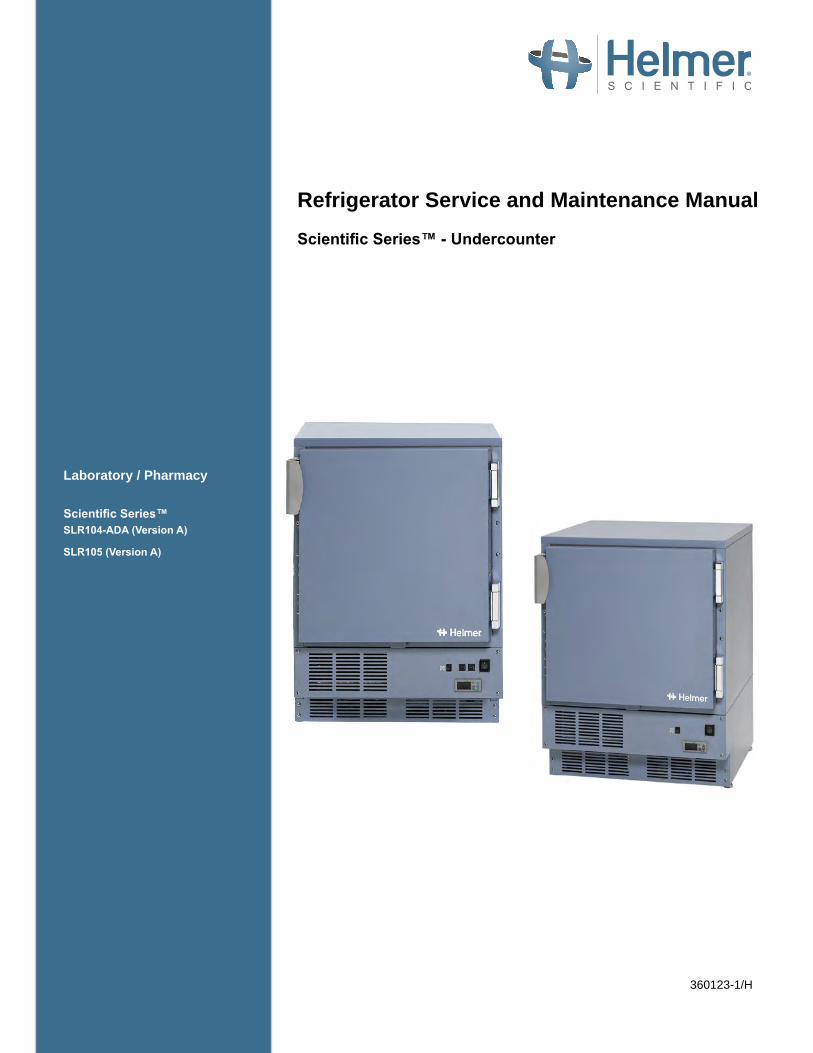
Refrigerator Service and Maintenance Manual
Scientific Series™ - Undercounter
360123-1/H
Laboratory / Pharmacy
Scientific Series™SLR104-ADA (Version A)
SLR105 (Version A)
Document Updates The document is furnished for information use only, is subject to change without notice and should not be construed as a commitment by Helmer Scientific. Helmer Scientific assumes no responsibility or liability for any errors or inaccuracies that may appear in the informational content contained in this material. For the purpose of clarity, Helmer Scientific considers only the most recent revision of this document to be valid.
Notices and DisclaimersConfidential / Proprietary NoticesUse of any portion(s) of this document to copy, translate, disassemble or decompile, or create or attempt to create by reverse engineering or otherwise the information from Helmer Scientific products is expressly prohibited.
Copyright and TrademarkCopyright © 2017 Helmer, Inc. Helmer®, i.Series®, i.C³®, Horizon Series™, Scientific Series™ and Rel.i™ are registered trademarks or trademarks of Helmer, Inc. in the United States of America. All other trademarks and registered trademarks are the property of their respective owners. Helmer, Inc., doing business as (DBA) Helmer Scientific and Helmer.
DisclaimerThis manual is intended as a guide to provide the operator with necessary instructions on the proper use and maintenance of certain Helmer Scientific products.Any failure to follow the instructions as described could result in impaired product function, injury to the operator or others, or void applicable product warranties. Helmer Scientific accepts no responsibility for liability resulting from improper use or maintenance of its products.The screenshots and component images appearing in this guide are provided for illustrative purposes only, and may vary slightly from the actual software screens and/or product components.
Helmer Scientific14400 Bergen BoulevardNoblesville, IN 46060 USA
www.helmerinc.com
ISO 13485:2003 CERTIFIED Part No. 360123-1/ Rev H
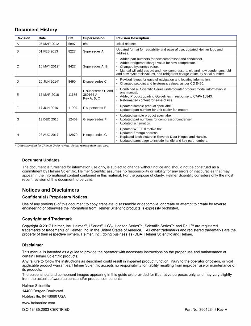
Document HistoryRevision Date CO Supersession Revision DescriptionA 05 MAR 2012 5897 n/a Initial release.
B 01 FEB 2013 8227 Supersedes A Updated format for readability and ease of use; updated Helmer logo and address.
C 16 MAY 2013* 8427 Supersedes A, B
• Added part numbers for new compressor and condenser.• Added refrigerant charge value for new compressor.• Changed hysteresis value.• Manual will address old and new compressors, old and new condensers, old and new hysteresis values, and refrigerant charge value, by serial number.
D 20 JUN 2014* 8490 D supersedes C • Revised layout for ease of navigation and locating information.• Changed setpoint and hysteresis values, as per CO 8490.
E 16 MAR 2016 11685E supersedes D and 360164-A Rev A, B, C
• Combined all Scientific Series undercounter product model information in one manual.• Added Product Loading Guidelines in response to CAPA 10843.• Reformatted content for ease of use.
F 17 JUN 2016 11909 F supersedes E • Updated sample product spec label.• Updated part number for unit cooler fan motors.
G 19 DEC 2016 12409 G supersedes F• Updated sample product spec label.• Updated part numbers for compressor/condenser.• Updated schematics.
H 23 AUG 2017 12970 H supersedes G
• Updated WEEE directive text.• Updated Emergo address.• Replaced latch picture in Reverse Door Hinges and Handle.• Updated parts page to include handle and key part numbers.
* Date submitted for Change Order review. Actual release date may vary.
Helmer Scientific Series™ Refrigerator - Undercounter Service and Maintenance Manual
360123-1/H ii
Contents1 About This Manual . . . . . . . . . . . . . . . . . . . . . . . . . . . . . . . . . . . . . . . . . . . . . . . . . . . . . . . . . . . . . . . . . . . . . . . . . . . . . . . . . . . 4
1.1 Safety Symbols and Precautions. . . . . . . . . . . . . . . . . . . . . . . . . . . . . . . . . . . . . . . . . . . . . . . . . . . . . . . . . . . . . . . . . . . . 41.2 Model and Input Power . . . . . . . . . . . . . . . . . . . . . . . . . . . . . . . . . . . . . . . . . . . . . . . . . . . . . . . . . . . . . . . . . . . . . . . . . . . 51.3 Product Labels. . . . . . . . . . . . . . . . . . . . . . . . . . . . . . . . . . . . . . . . . . . . . . . . . . . . . . . . . . . . . . . . . . . . . . . . . . . . . . . . . . 5
2 Installation and Configuration . . . . . . . . . . . . . . . . . . . . . . . . . . . . . . . . . . . . . . . . . . . . . . . . . . . . . . . . . . . . . . . . . . . . . . . . . 62.1 Location Requirements . . . . . . . . . . . . . . . . . . . . . . . . . . . . . . . . . . . . . . . . . . . . . . . . . . . . . . . . . . . . . . . . . . . . . . . . . . . 62.2 Placement and Leveling . . . . . . . . . . . . . . . . . . . . . . . . . . . . . . . . . . . . . . . . . . . . . . . . . . . . . . . . . . . . . . . . . . . . . . . . . . 62.3 Stacked Undercounter Units . . . . . . . . . . . . . . . . . . . . . . . . . . . . . . . . . . . . . . . . . . . . . . . . . . . . . . . . . . . . . . . . . . . . . . . 62.4 Prepare for Monitoring . . . . . . . . . . . . . . . . . . . . . . . . . . . . . . . . . . . . . . . . . . . . . . . . . . . . . . . . . . . . . . . . . . . . . . . . . . . . 62.5 Configure Storage . . . . . . . . . . . . . . . . . . . . . . . . . . . . . . . . . . . . . . . . . . . . . . . . . . . . . . . . . . . . . . . . . . . . . . . . . . . . . . . 82.6 Reverse Door Hinges and Handle . . . . . . . . . . . . . . . . . . . . . . . . . . . . . . . . . . . . . . . . . . . . . . . . . . . . . . . . . . . . . . . . . . . 9
3 Controls . . . . . . . . . . . . . . . . . . . . . . . . . . . . . . . . . . . . . . . . . . . . . . . . . . . . . . . . . . . . . . . . . . . . . . . . . . . . . . . . . . . . . . . . . . . 123.1 Error Code Reference . . . . . . . . . . . . . . . . . . . . . . . . . . . . . . . . . . . . . . . . . . . . . . . . . . . . . . . . . . . . . . . . . . . . . . . . . . . 123.2 Settings . . . . . . . . . . . . . . . . . . . . . . . . . . . . . . . . . . . . . . . . . . . . . . . . . . . . . . . . . . . . . . . . . . . . . . . . . . . . . . . . . . . . . . 12
4 Maintenance . . . . . . . . . . . . . . . . . . . . . . . . . . . . . . . . . . . . . . . . . . . . . . . . . . . . . . . . . . . . . . . . . . . . . . . . . . . . . . . . . . . . . . . 144.1 Test and Replace Chart Recorder Back-up Battery (if included) . . . . . . . . . . . . . . . . . . . . . . . . . . . . . . . . . . . . . . . . . . . 144.2 Check Probe Bottle (if installed) . . . . . . . . . . . . . . . . . . . . . . . . . . . . . . . . . . . . . . . . . . . . . . . . . . . . . . . . . . . . . . . . . . . 144.3 Clean the Refrigerator . . . . . . . . . . . . . . . . . . . . . . . . . . . . . . . . . . . . . . . . . . . . . . . . . . . . . . . . . . . . . . . . . . . . . . . . . . . 14
5 Service . . . . . . . . . . . . . . . . . . . . . . . . . . . . . . . . . . . . . . . . . . . . . . . . . . . . . . . . . . . . . . . . . . . . . . . . . . . . . . . . . . . . . . . . . . . . 165.1 Recharge Refrigerant . . . . . . . . . . . . . . . . . . . . . . . . . . . . . . . . . . . . . . . . . . . . . . . . . . . . . . . . . . . . . . . . . . . . . . . . . . . 165.2 Replace LED Lamps (if installed) . . . . . . . . . . . . . . . . . . . . . . . . . . . . . . . . . . . . . . . . . . . . . . . . . . . . . . . . . . . . . . . . . . 165.3 Remove / Replace Unit Cooler Cover . . . . . . . . . . . . . . . . . . . . . . . . . . . . . . . . . . . . . . . . . . . . . . . . . . . . . . . . . . . . . . . 16
6 Troubleshooting . . . . . . . . . . . . . . . . . . . . . . . . . . . . . . . . . . . . . . . . . . . . . . . . . . . . . . . . . . . . . . . . . . . . . . . . . . . . . . . . . . . . 186.1 General Operation Problems . . . . . . . . . . . . . . . . . . . . . . . . . . . . . . . . . . . . . . . . . . . . . . . . . . . . . . . . . . . . . . . . . . . . . . 186.2 Chamber Temperature Problems . . . . . . . . . . . . . . . . . . . . . . . . . . . . . . . . . . . . . . . . . . . . . . . . . . . . . . . . . . . . . . . . . . 186.3 Condensation Problems . . . . . . . . . . . . . . . . . . . . . . . . . . . . . . . . . . . . . . . . . . . . . . . . . . . . . . . . . . . . . . . . . . . . . . . . . 19
7 Parts . . . . . . . . . . . . . . . . . . . . . . . . . . . . . . . . . . . . . . . . . . . . . . . . . . . . . . . . . . . . . . . . . . . . . . . . . . . . . . . . . . . . . . . . . . . . . 20
8 Schematics . . . . . . . . . . . . . . . . . . . . . . . . . . . . . . . . . . . . . . . . . . . . . . . . . . . . . . . . . . . . . . . . . . . . . . . . . . . . . . . . . . . . . . . . 228.1 SLR model; 104 and 105 configuration . . . . . . . . . . . . . . . . . . . . . . . . . . . . . . . . . . . . . . . . . . . . . . . . . . . . . . . . . . . . . . 22
Appendix A: Compliance . . . . . . . . . . . . . . . . . . . . . . . . . . . . . . . . . . . . . . . . . . . . . . . . . . . . . . . . . . . . . . . . . . . . . . . . . . . . . . . . 24
Appendix B: Warranty . . . . . . . . . . . . . . . . . . . . . . . . . . . . . . . . . . . . . . . . . . . . . . . . . . . . . . . . . . . . . . . . . . . . . . . . . . . . . . . . . . . 25
Helmer Scientific Series™ Refrigerator - Undercounter Service and Maintenance Manual
360123-1/H 3
1 About This ManualThis manual provides information on how to use Scientific Series™ undercounter laboratory and pharmacy refrigerators. It is intended for use by end users of the refrigerator and authorized service technicians.
Models are indicated by a distinguishing model number that corresponds to the series, type, number of doors, and capacity of the refrigerator. For example, “SLR104” refers to an Scientific Series Laboratory Refrigerator with 1 door and a capacity of 4 cu ft while “SLR105” refers to a Scientific Series Laboratory Refrigerator with 1 door and a capacity of 5 cu ft.
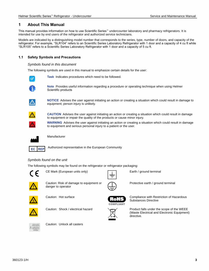
1.1 Safety Symbols and Precautions
Symbols found in this document
The following symbols are used in this manual to emphasize certain details for the user:
Task Indicates procedures which need to be followed.
Note Provides useful information regarding a procedure or operating technique when using Helmer Scientific products
NOTICE Advises the user against initiating an action or creating a situation which could result in damage to equipment; person injury is unlikely.
CAUTION Advises the user against initiating an action or creating a situation which could result in damage to equipment or impair the quality of the products or cause minor injury.WARNING Advises the user against initiating an action or creating a situation which could result in damage to equipment and serious personal injury to a patient or the user.
Manufacturer
EC REP Authorized representative in the European Community
Symbols found on the unit
The following symbols may be found on the refrigerator or refrigerator packaging:
CE Mark (European units only) Earth / ground terminal
Caution: Risk of damage to equipment or danger to operator
Protective earth / ground terminal
Caution: Hot surface Compliance with Restriction of Hazardous Substances Directive
Caution: Shock / electrical hazard Product falls under the scope of the WEEE (Waste Electrical and Electronic Equipment) directive.
Caution: Unlock all casters
Helmer Scientific Series™ Refrigerator - Undercounter Service and Maintenance Manual
360123-1/H 4
Safety Precautions Avoiding Injury
Review safety instructions before installing, using or maintaining the equipment. ♦ Before moving unit, ensure door is closed and casters (if installed) are unlocked and free of debris. ♦ Before moving unit, disconnect the AC power cord and secure the cord. ♦ Never physically restrict any moving component. ♦ Avoid removing electrical service panels and access panels unless so instructed. ♦ Keep hands away from pinch points when closing the door. ♦ Avoid sharp edges when working inside the electrical compartment and refrigeration compartment. ♦ Ensure biological materials are stored at recommended temperatures determined by standards, literature, or good
laboratory practices. ♦ Proceed with caution when adding and removing samples from the refrigerator. ♦ Use manufacturer supplied power cord only. ♦ Using the equipment in a manner not specified by Helmer Scientific may impair the protection provided by the equipment. ♦ Ensure biological materials are stored safely, in accordance with all applicable organizational, regulatory, and legal
requirements. ♦ The refrigerator is not considered to be a storage cabinet for flammable or hazardous materials.
CAUTIONDecontaminate parts prior to sending for service or repair. Contact Helmer Scientific or your distributor for decontamination instructions and a Return Authorization Number.
1 .2 Model and Input Power Note
Service information varies depending on the model and power requirements.
Table 1. Model and Input Power
Model Voltage FrequencyCurrent
Draw
104 115V 60 Hz 5.0 A
105
115V 60 Hz 5.0 A230V 50 Hz 4.0 A230V 60 Hz 3.25 A
* Amperage values are subject to change. Refer to the product specification label on your unit for current values.
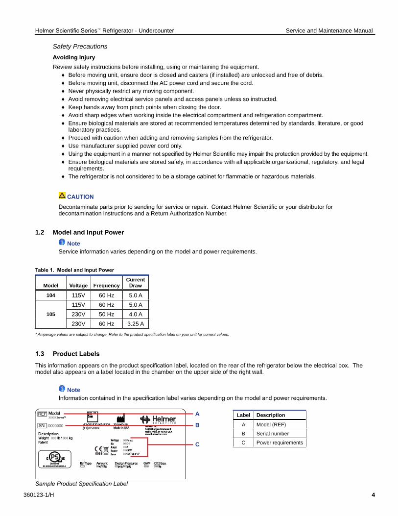
1.3 Product Labels
This information appears on the product specification label, located on the rear of the refrigerator below the electrical box. The model also appears on a label located in the chamber on the upper side of the right wall.
NoteInformation contained in the specification label varies depending on the model and power requirements.
Sample Product Specification Label
C
B
A Label Description
A Model (REF)
B Serial number
C Power requirements
Helmer Scientific Series™ Refrigerator - Undercounter Service and Maintenance Manual
360123-1/H 5
2 Installation and Configuration2.1 Location Requirements ♦ Grounded outlet meeting the electrical requirements listed on the product specification label. ♦ Clear of direct sunlight, high temperature sources, and heating and air conditioning vents. ♦ Minimum 3“ (76 mm) of space behind unit. ♦ Meets limits specified for ambient temperature (15˚C to 32˚C) and relative humidity.
2 .2 Placement and Leveling
CAUTION• To prevent tipping, ensure the casters (if installed) are unlocked and the door is closed before moving the refrigerator. • Do not sit, lean, push or place heavy objects on top surface.
1. Move refrigerator into place. Lock casters if installed.2. Ensure refrigerator is level.
NoteHelmer recommends the use of leveling feet and wall and floor brackets (PN 400472-2) for stabilization. Contact Helmer Technical Service for parts and instruction.
2.3 Stacked Undercounter Units
CAUTION• For stacked configuration, both units must have leveling feet installed.• Back brace bars and front stabilizing brackets must be installed (Blue - PN 400821-1; Stainless Steel - PN 400821-2).• When stacking units, place the heavier unit on the bottom.• Do not open multiple loaded drawers or baskets at the same time.
Contact Helmer or your distributor for more information regarding the stacking kit and methods to secure both units to the wall and / or floor.
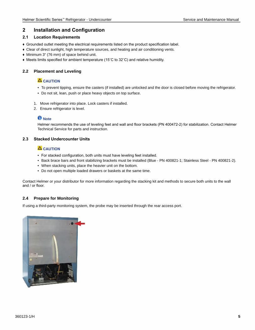
2 .4 Prepare for Monitoring
If using a third-party monitoring system, the probe may be inserted through the rear access port.
Helmer Scientific Series™ Refrigerator - Undercounter Service and Maintenance Manual
360123-1/H 6
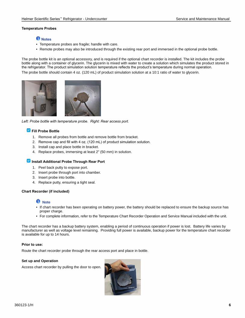
Temperature Probes
Notes• Temperature probes are fragile; handle with care.• Remote probes may also be introduced through the existing rear port and immersed in the optional probe bottle.
The probe bottle kit is an optional accessory, and is required if the optional chart recorder is installed. The kit includes the probe bottle along with a container of glycerin. The glycerin is mixed with water to create a solution which simulates the product stored in the refrigerator. The product simulation solution temperature reflects the product’s temperature during normal operation.The probe bottle should contain 4 oz. (120 mL) of product simulation solution at a 10:1 ratio of water to glycerin.
Left: Probe bottle with temperature probe. Right: Rear access port.
Fill Probe Bottle1. Remove all probes from bottle and remove bottle from bracket.2. Remove cap and fill with 4 oz. (120 mL) of product simulation solution.3. Install cap and place bottle in bracket.4. Replace probes, immersing at least 2” (50 mm) in solution.
Install Additional Probe Through Rear Port1. Peel back putty to expose port.2. Insert probe through port into chamber.3. Insert probe into bottle.4. Replace putty, ensuring a tight seal.
Chart Recorder (if included)
Note• If chart recorder has been operating on battery power, the battery should be replaced to ensure the backup source has proper charge.• For complete information, refer to the Temperature Chart Recorder Operation and Service Manual included with the unit.
The chart recorder has a backup battery system, enabling a period of continuous operation if power is lost. Battery life varies by manufacturer as well as voltage level remaining. Providing full power is available, backup power for the temperature chart recorder is available for up to 14 hours.
Prior to use:Route the chart recorder probe through the rear access port and place in bottle.
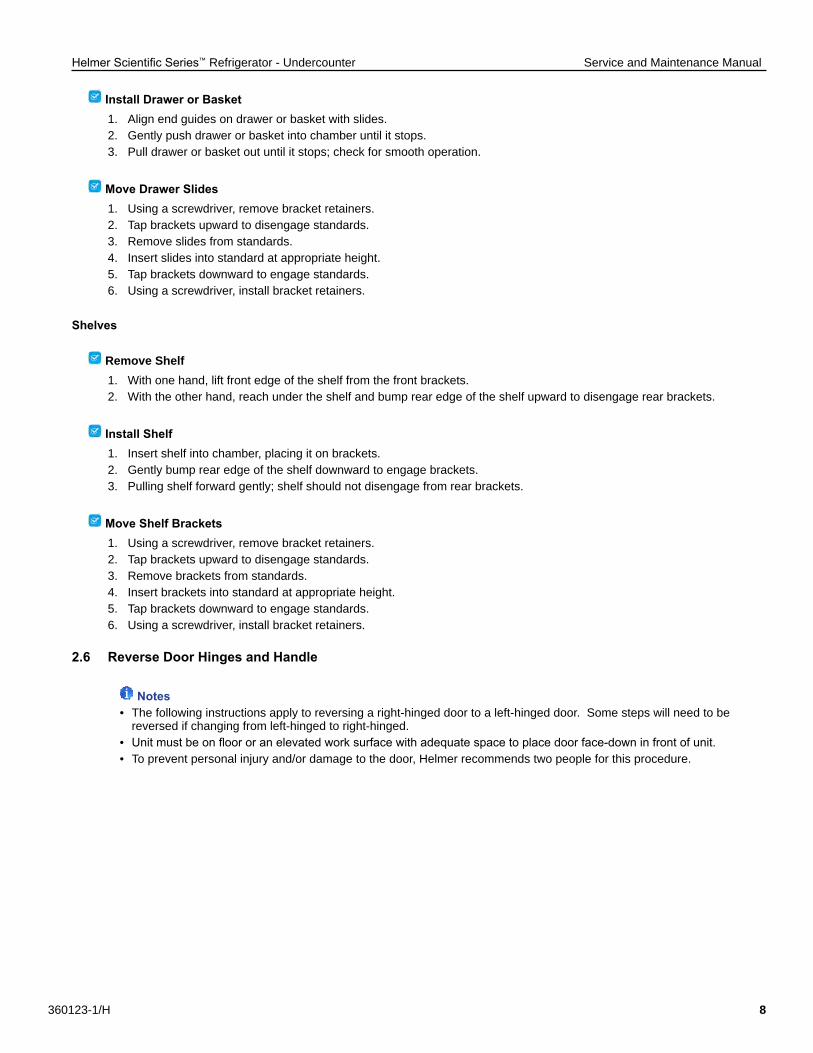
Set up and OperationAccess chart recorder by pulling the door to open.
Helmer Scientific Series™ Refrigerator - Undercounter Service and Maintenance Manual
360123-1/H 7
Install BatteryConnect the leads to the battery to provide back-up power to the chart recorder.
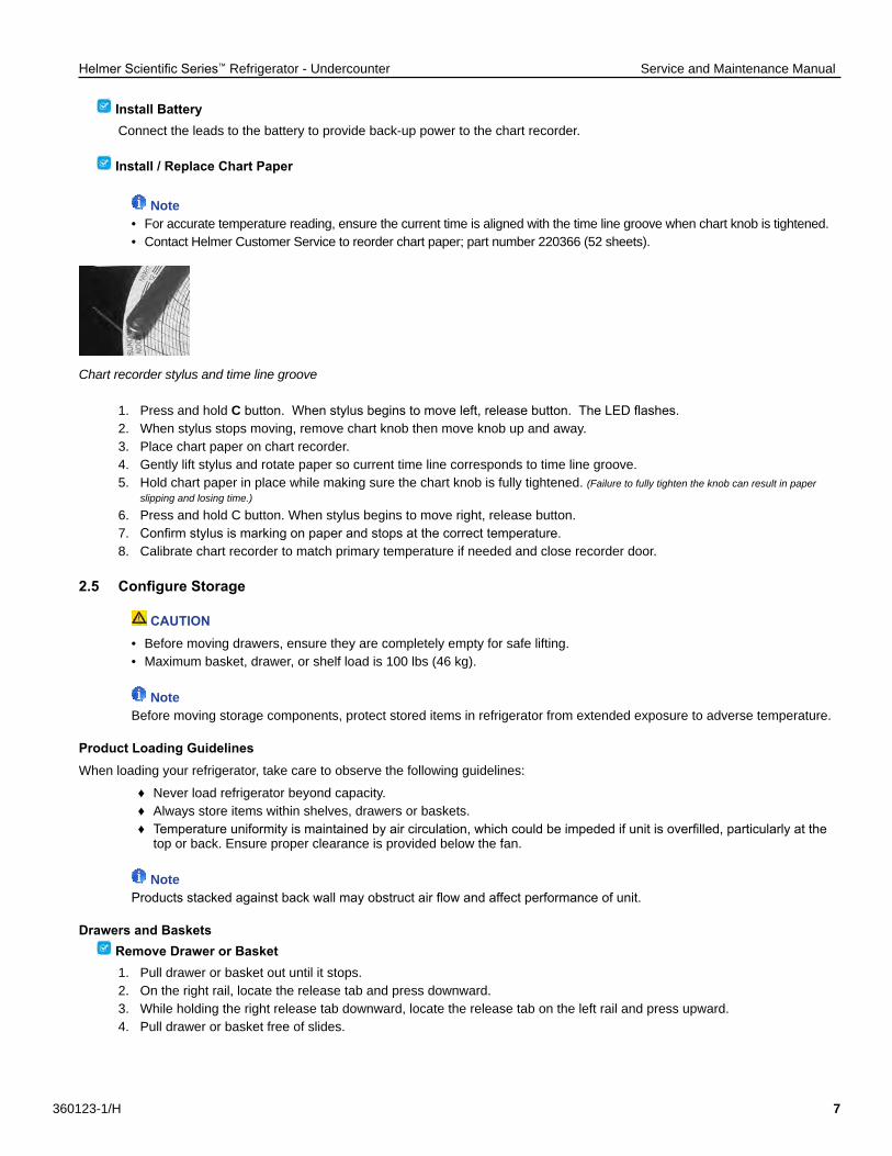
Install / Replace Chart Paper
Note• For accurate temperature reading, ensure the current time is aligned with the time line groove when chart knob is tightened.• Contact Helmer Customer Service to reorder chart paper; part number 220366 (52 sheets).
Chart recorder stylus and time line groove
1. Press and hold C button. When stylus begins to move left, release button. The LED flashes.2. When stylus stops moving, remove chart knob then move knob up and away.3. Place chart paper on chart recorder.4. Gently lift stylus and rotate paper so current time line corresponds to time line groove.5. Hold chart paper in place while making sure the chart knob is fully tightened. (Failure to fully tighten the knob can result in paper slipping and losing time.)
6. Press and hold C button. When stylus begins to move right, release button.7. Confirm stylus is marking on paper and stops at the correct temperature.8. Calibrate chart recorder to match primary temperature if needed and close recorder door.
2.5 Configure Storage
CAUTION• Before moving drawers, ensure they are completely empty for safe lifting.• Maximum basket, drawer, or shelf load is 100 lbs (46 kg).
NoteBefore moving storage components, protect stored items in refrigerator from extended exposure to adverse temperature.
Product Loading GuidelinesWhen loading your refrigerator, take care to observe the following guidelines:
♦ Never load refrigerator beyond capacity. ♦ Always store items within shelves, drawers or baskets. ♦ Temperature uniformity is maintained by air circulation, which could be impeded if unit is overfilled, particularly at the
top or back. Ensure proper clearance is provided below the fan.
NoteProducts stacked against back wall may obstruct air flow and affect performance of unit.
Drawers and Baskets Remove Drawer or Basket1. Pull drawer or basket out until it stops.2. On the right rail, locate the release tab and press downward.3. While holding the right release tab downward, locate the release tab on the left rail and press upward.4. Pull drawer or basket free of slides.
Helmer Scientific Series™ Refrigerator - Undercounter Service and Maintenance Manual
360123-1/H 8
Install Drawer or Basket1. Align end guides on drawer or basket with slides.2. Gently push drawer or basket into chamber until it stops.3. Pull drawer or basket out until it stops; check for smooth operation.
Move Drawer Slides1. Using a screwdriver, remove bracket retainers.2. Tap brackets upward to disengage standards.3. Remove slides from standards.4. Insert slides into standard at appropriate height.5. Tap brackets downward to engage standards.6. Using a screwdriver, install bracket retainers.
Shelves
Remove Shelf1. With one hand, lift front edge of the shelf from the front brackets.2. With the other hand, reach under the shelf and bump rear edge of the shelf upward to disengage rear brackets.
Install Shelf1. Insert shelf into chamber, placing it on brackets.2. Gently bump rear edge of the shelf downward to engage brackets.3. Pulling shelf forward gently; shelf should not disengage from rear brackets.
Move Shelf Brackets1. Using a screwdriver, remove bracket retainers.2. Tap brackets upward to disengage standards.3. Remove brackets from standards.4. Insert brackets into standard at appropriate height.5. Tap brackets downward to engage standards.6. Using a screwdriver, install bracket retainers.
2.6 Reverse Door Hinges and Handle
Notes• The following instructions apply to reversing a right-hinged door to a left-hinged door. Some steps will need to be reversed if changing from left-hinged to right-hinged.• Unit must be on floor or an elevated work surface with adequate space to place door face-down in front of unit.• To prevent personal injury and/or damage to the door, Helmer recommends two people for this procedure.
Helmer Scientific Series™ Refrigerator - Undercounter Service and Maintenance Manual
360123-1/H 9
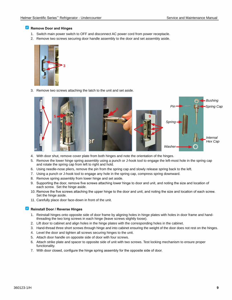
Remove Door and Hinges1. Switch main power switch to OFF and disconnect AC power cord from power receptacle.2. Remove two screws securing door handle assembly to the door and set assembly aside.
3. Remove two screws attaching the latch to the unit and set aside.
4. With door shut, remove cover plate from both hinges and note the orientation of the hinges.5. Remove the lower hinge spring assembly using a punch or J-hook tool to engage the left-most hole in the spring cap and rotate the spring cap from left to right and hold.6. Using needle-nose pliers, remove the pin from the spring cap and slowly release spring back to the left.7. Using a punch or J-hook tool to engage any hole in the spring cap, compress spring downward.8. Remove spring assembly from lower hinge and set aside.9. Supporting the door, remove five screws attaching lower hinge to door and unit, and noting the size and location of each screw. Set the hinge aside. 10. Remove the five screws attaching the upper hinge to the door and unit, and noting the size and location of each screw. Set the hinge aside.11. Carefully place door face-down in front of the unit.
Reinstall Door / Reverse Hinges1. Reinstall hinges onto opposite side of door frame by aligning holes in hinge plates with holes in door frame and hand- threading the two long screws in each hinge (leave screws slightly loose).2. Lift door to cabinet and align holes in the hinge plates with the corresponding holes in the cabinet.3. Hand-thread three short screws through hinge and into cabinet ensuring the weight of the door does not rest on the hinges.4. Level the door and tighten all screws securing hinges to the unit.5. Attach door handle on opposite side of door with four screws.6. Attach strike plate and spacer to opposite side of unit with two screws. Test locking mechanism to ensure proper functionality.7. With door closed, configure the hinge spring assembly for the opposite side of door.
3
5
6
94 Spring
Washer
Pin
Internal Hex Cap
Spring Cap
Bushing
Helmer Scientific Series™ Refrigerator - Undercounter Service and Maintenance Manual
360123-1/H 10
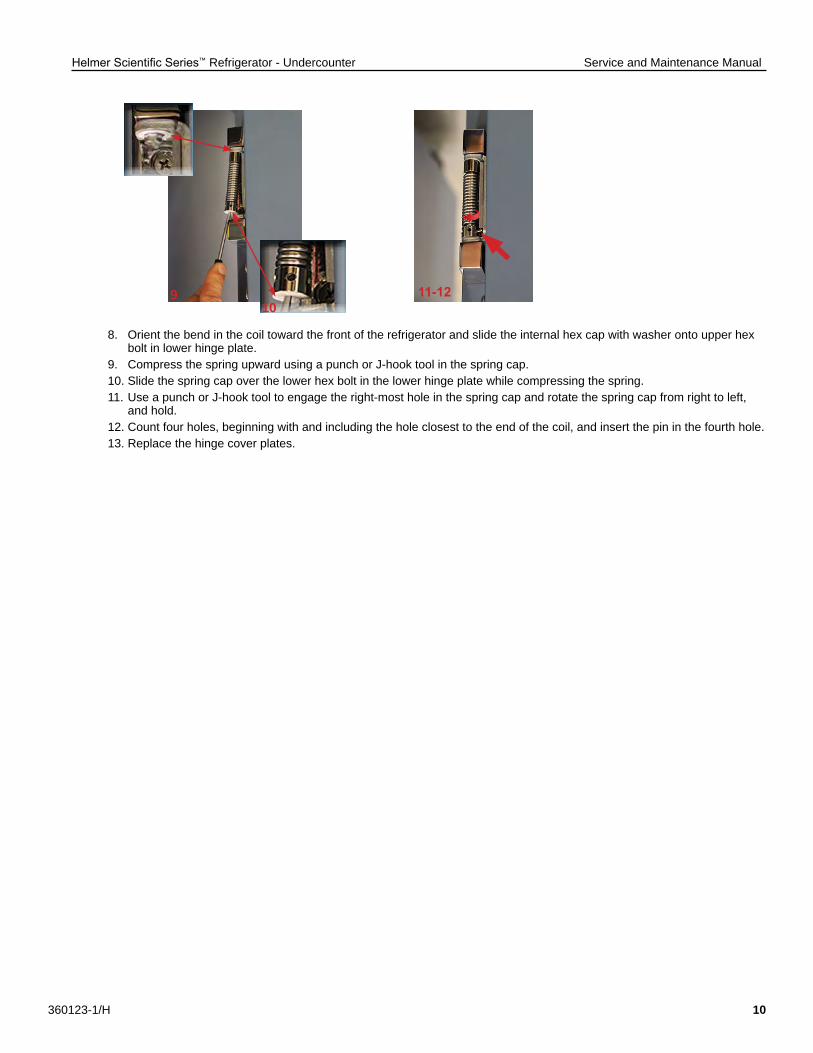
8. Orient the bend in the coil toward the front of the refrigerator and slide the internal hex cap with washer onto upper hex bolt in lower hinge plate.9. Compress the spring upward using a punch or J-hook tool in the spring cap.10. Slide the spring cap over the lower hex bolt in the lower hinge plate while compressing the spring.11. Use a punch or J-hook tool to engage the right-most hole in the spring cap and rotate the spring cap from right to left, and hold.12. Count four holes, beginning with and including the hole closest to the end of the coil, and insert the pin in the fourth hole.13. Replace the hinge cover plates.
9 11-1210
Helmer Scientific Series™ Refrigerator - Undercounter Service and Maintenance Manual
360123-1/H 11
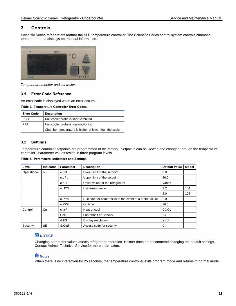
3 ControlsScientific Series refrigerators feature the SLR temperature controller. The Scientific Series control system controls chamber temperature and displays operational information.
Temperature monitor and controller.
3.1 Error Code Reference
An error code is displayed when an error occurs.
Table 2. Temperature Controller Error Codes
Error Code DescriptionPSC Unit cooler probe is short-circuited
PFA Unit cooler probe is malfunctioning
---- Chamber temperature is higher or lower than the scale
3.2 Settings
Temperature controller setpoints are programmed at the factory. Setpoints can be viewed and changed through the temperature controller. Parameter values reside in three program levels.
Table 3. Parameters, Indicators and Settings
Level Indicator Parameter Description Default Value ModelOperational ou o.LoL Lower limit of the setpoint 0.0
o.uPL Upper limit of the setpoint 20.0
o.oFF Offset value for the refrigerator Varies
o.HYS Hysteresis value 1.2 104
2.0 105
o.PPn Run time for compressor in the event of a probe failure 2.0
o.PPF Off time 20.0
Control Cn c.tYP Heat or cool COOL
Unit Fahrenheit or Celsius °C
drES Display resolution YES
Security SE S.Cod Access code for security 0
NOTICEChanging parameter values affects refrigerator operation. Helmer does not recommend changing the default settings. Contact Helmer Technical Service for more information.
NotesWhen there is no interaction for 25 seconds, the temperature controller exits program mode and returns to normal mode.
Helmer Scientific Series™ Refrigerator - Undercounter Service and Maintenance Manual
360123-1/H 12
View or Change Parameter Values:
1. Press and hold the UP and DOWN arrow buttons simultaneously for approximately three seconds to enter program mode.2. Press and release the UP or DOWN arrow buttons until the desired program level flashes on the display.3. Press and release the DOWN arrow button until the desired parameter flashes on the display.4. Press and hold the SET button. While holding the SET button, press the UP or DOWN arrow buttons to change the value.5. Release all buttons to exit the parameter and save new setting.6. Repeat steps 2 through 4 to access another parameter, or to view or change parameter values in the selected level.7. Press and hold the UP and DOWN arrow buttons simultaneously for approximately one second to exit program mode. The current chamber temperature is displayed.
Control SensorThe temperature controller senses the unit cooler temperature through the control probe in the unit cooler. The unit cooler temperature typically varies from the chamber temperature, so an offset value is used by the control system to compensate for the difference.
The temperature controller adjusts chamber temperature around the refrigerator setpoint by activating the compressor when the control probe registers above the setpoint based on the hysteresis value.
NoteControl Sensor Offset is factory-preset and changing this value is not recommended. Contact Helmer Technical Service for questions regarding the Control Sensor Offset
HysteresisHysteresis is the allowable temperature control variance on each side of the refrigerator setpoint.
NoteThe Hysteresis value is factory-preset and should not be changed unless directed by Helmer Technical Service.
Helmer Scientific Series™ Refrigerator - Undercounter Service and Maintenance Manual
360123-1/H 13
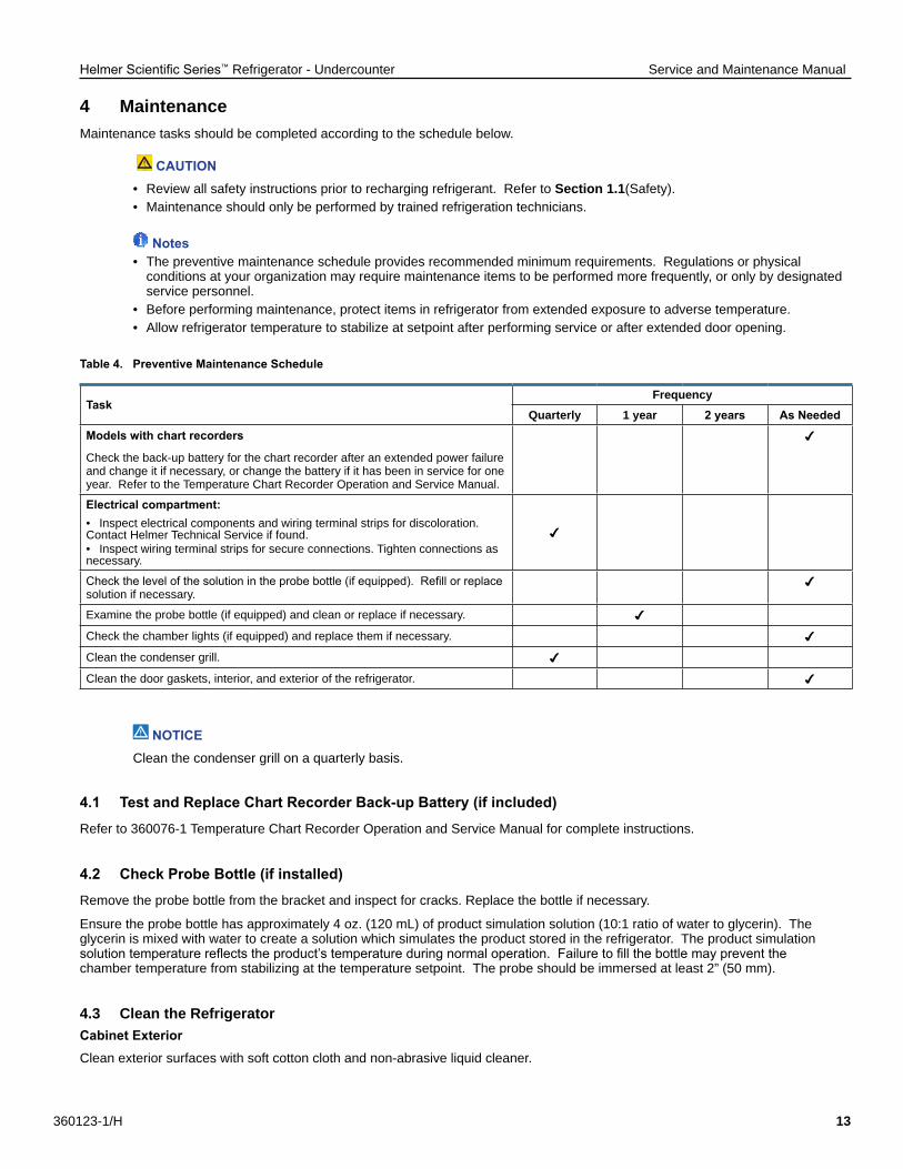
4 MaintenanceMaintenance tasks should be completed according to the schedule below.
CAUTION• Review all safety instructions prior to recharging refrigerant. Refer to Section 1 .1(Safety).• Maintenance should only be performed by trained refrigeration technicians.
Notes• The preventive maintenance schedule provides recommended minimum requirements. Regulations or physical conditions at your organization may require maintenance items to be performed more frequently, or only by designated service personnel.• Before performing maintenance, protect items in refrigerator from extended exposure to adverse temperature.• Allow refrigerator temperature to stabilize at setpoint after performing service or after extended door opening.
Table 4. Preventive Maintenance Schedule
TaskFrequency
Quarterly 1 year 2 years As NeededModels with chart recorders
Check the back-up battery for the chart recorder after an extended power failure and change it if necessary, or change the battery if it has been in service for one year. Refer to the Temperature Chart Recorder Operation and Service Manual.
Electrical compartment:• Inspect electrical components and wiring terminal strips for discoloration. Contact Helmer Technical Service if found. • Inspect wiring terminal strips for secure connections. Tighten connections as necessary.
Check the level of the solution in the probe bottle (if equipped). Refill or replace solution if necessary.
Examine the probe bottle (if equipped) and clean or replace if necessary.
Check the chamber lights (if equipped) and replace them if necessary.
Clean the condenser grill.
Clean the door gaskets, interior, and exterior of the refrigerator.
NOTICEClean the condenser grill on a quarterly basis.
4.1 Test and Replace Chart Recorder Back-up Battery (if included)
Refer to 360076-1 Temperature Chart Recorder Operation and Service Manual for complete instructions.
4.2 Check Probe Bottle (if installed)
Remove the probe bottle from the bracket and inspect for cracks. Replace the bottle if necessary.
Ensure the probe bottle has approximately 4 oz. (120 mL) of product simulation solution (10:1 ratio of water to glycerin). The glycerin is mixed with water to create a solution which simulates the product stored in the refrigerator. The product simulation solution temperature reflects the product’s temperature during normal operation. Failure to fill the bottle may prevent the chamber temperature from stabilizing at the temperature setpoint. The probe should be immersed at least 2” (50 mm).
4 .3 Clean the RefrigeratorCabinet ExteriorClean exterior surfaces with soft cotton cloth and non-abrasive liquid cleaner.
Helmer Scientific Series™ Refrigerator - Undercounter Service and Maintenance Manual
360123-1/H 14
CAUTION The condensate evaporator and water evaporation tray are hot.
Cabinet InteriorClean painted surfaces with mild detergent. Clean stainless steel surfaces with a general-purpose laboratory cleaner suitable for stainless steel.
Condenser Grill
CAUTIONDisconnect refrigerator from AC power when cleaning condenser grill.
If the refrigerator is located in an environment where it is exposed to excessive lint or dust, the condenser grill may require cleaning more frequently than stated in preventive maintenance schedule.
Clean the condenser grill using a soft brush and a vacuum cleaner.
Door GasketsClean with soft cloth and mild soap and water solution.
Probe Bottles (if installed)
Clean and Refill Probe Bottles1. Remove all probes from bottle.2. Remove bottle from bracket and empty any remaining solution.3. Clean bottle with a 1:9 ratio of bleach to water solution or a company approved equivalent oxidizing cleaner/disinfectant.4. Refill bottle with 4 oz. (120 mL) of product simulation solution (10:1 ratio of water to glycerin).5. Cap bottle tightly to minimize evaporation.6. Place bottle in bracket.7. Replace probes, immersing at least 2” (50 mm).
Helmer Scientific Series™ Refrigerator - Undercounter Service and Maintenance Manual
360123-1/H 15
5 Service5 .1 Recharge Refrigerant
CAUTION• Review all safety instructions prior to recharging refrigerant. Refer to Section 1.1.• Maintenance should only be performed by trained refrigeration technicians.
Notes• Use only non-CFC R134A refrigerant.• Pressure readings may vary based on chamber temperature and ambient air temperature.• Normal low side pressures are 16 psi to 18 psi when unit is functioning at standard operating temperatures and measured at the end of the compressor cycle.• If a refrigerant leak is suspected, Helmer recommends finding and fixing the leak prior to recharging the unit.
Full initial refrigerant charge varies by size of compressor and date of manufacture. Applicable charge values are found in Table 5.
Table 5. Initial Charge by Horsepower
Horsepower Refrigerant Initial Charge Serial Number
1/4 R134A 9.5 oz. (269 g) less than 2004753
1/6 R134A 4.5 oz. (128 g) 2004753 and greater
5.2 Replace LED Lamps (if installed)1. Switch AC ON/OFF switch OFF. Disconnect the battery.2. Using a screwdriver, remove lamp strip from chamber.3. Unsnap the defective LED and disconnect wires.4. Snap new LED onto the lamp strip.5. Connect the wires.6. Using a screwdriver, attach lamp strip to chamber wall.7. Switch AC ON/OFF switch ON. Reconnect the battery.
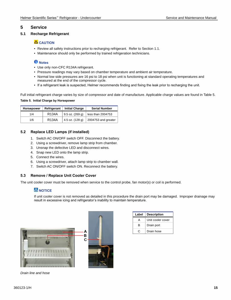
5.3 Remove / Replace Unit Cooler Cover
The unit cooler cover must be removed when service to the control probe, fan motor(s) or coil is performed.
NOTICEIf unit cooler cover is not removed as detailed in this procedure the drain port may be damaged. Improper drainage may result in excessive icing and refrigerator’s inability to maintain temperature.
Drain line and hose
Label Description
A Unit cooler cover
B Drain port
C Drain hose
CBA
Helmer Scientific Series™ Refrigerator - Undercounter Service and Maintenance Manual
360123-1/H 16
Remove the Unit Cooler Cover
CAUTIONThe condensate evaporator and water evaporation tray are hot.
1. Switch AC ON/OFF switch OFF. Disconnect AC power cord from power receptacle.2. Remove top drawer, basket, or shelf from the chamber.3. On the back of the chamber, peel putty back to expose drain hose.4. Pull drain hose downward while gently twisting to remove from unit cooler drain port.5. Push drain hose out through rear of chamber.6. Hold unit cooler cover in place to prevent dropping. Using a 5/16”socket wrench, remove four screws securing the unit cooler cover.7. Carefully lower unit cooler cover to avoid damage to the fan wiring.
Install the Unit Cooler Cover1. Verify unit cooler wiring is connected and routed correctly.2. Lift unit cooler cover into place. Front edge of the cover should be behind the unit cooler case.3. Using a 5/16” socket wrench, install four screws to secure the unit cooler cover.4. Insert drain hose through hole in the rear of the refrigerator.5. Push drain hose upward, toward the unit cooler drain port.6. In the chamber, attach drain hose to unit cooler drain port.7. Reinstall top drawer, basket, or shelf if previously removed.8. On the back of the chamber, press putty around the drain hose.9. Insert AC power cord into power receptacle. Switch AC ON/OFF switch ON.
Helmer Scientific Series™ Refrigerator - Undercounter Service and Maintenance Manual
360123-1/H 17
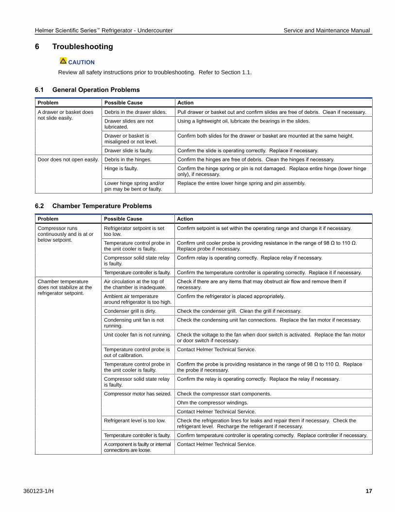
6 Troubleshooting
CAUTIONReview all safety instructions prior to troubleshooting. Refer to Section 1.1.
6.1 General Operation Problems
Problem Possible Cause Action
A drawer or basket does not slide easily.
Debris in the drawer slides. Pull drawer or basket out and confirm slides are free of debris. Clean if necessary.
Drawer slides are not lubricated.
Using a lightweight oil, lubricate the bearings in the slides.
Drawer or basket is misaligned or not level.
Confirm both slides for the drawer or basket are mounted at the same height.
Drawer slide is faulty. Confirm the slide is operating correctly. Replace if necessary.
Door does not open easily. Debris in the hinges. Confirm the hinges are free of debris. Clean the hinges if necessary.
Hinge is faulty. Confirm the hinge spring or pin is not damaged. Replace entire hinge (lower hinge only), if necessary.
Lower hinge spring and/or pin may be bent or faulty.
Replace the entire lower hinge spring and pin assembly.
6.2 Chamber Temperature Problems
Problem Possible Cause Action
Compressor runs continuously and is at or below setpoint.
Refrigerator setpoint is set too low.
Confirm setpoint is set within the operating range and change it if necessary.
Temperature control probe in the unit cooler is faulty.
Confirm unit cooler probe is providing resistance in the range of 98 Ω to 110 Ω. Replace probe if necessary.
Compressor solid state relay is faulty.
Confirm relay is operating correctly. Replace relay if necessary.
Temperature controller is faulty. Confirm the temperature controller is operating correctly. Replace it if necessary.
Chamber temperature does not stabilize at the refrigerator setpoint.
Air circulation at the top of the chamber is inadequate.
Check if there are any items that may obstruct air flow and remove them if necessary.
Ambient air temperature around refrigerator is too high.
Confirm the refrigerator is placed appropriately.
Condenser grill is dirty. Check the condenser grill. Clean the grill if necessary.
Condensing unit fan is not running.
Check the condensing unit fan connections. Replace the fan motor if necessary.
Unit cooler fan is not running. Check the voltage to the fan when door switch is activated. Replace the fan motor or door switch if necessary.
Temperature control probe is out of calibration.
Contact Helmer Technical Service.
Temperature control probe in the unit cooler is faulty.
Confirm the probe is providing resistance in the range of 98 Ω to 110 Ω. Replace the probe if necessary.
Compressor solid state relay is faulty.
Confirm the relay is operating correctly. Replace the relay if necessary.
Compressor motor has seized. Check the compressor start components.
Ohm the compressor windings.
Contact Helmer Technical Service.
Refrigerant level is too low. Check the refrigeration lines for leaks and repair them if necessary. Check the refrigerant level. Recharge the refrigerant if necessary.
Temperature controller is faulty. Confirm temperature controller is operating correctly. Replace controller if necessary.
A component is faulty or internal connections are loose.
Contact Helmer Technical Service.
Helmer Scientific Series™ Refrigerator - Undercounter Service and Maintenance Manual
360123-1/H 18
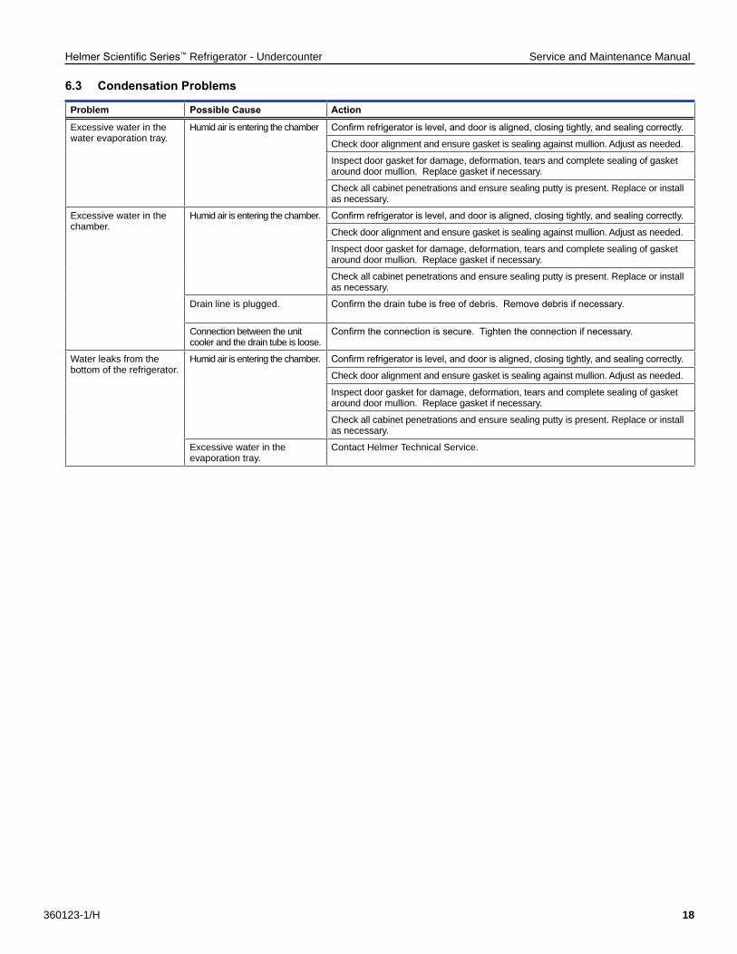
6.3 Condensation Problems
Problem Possible Cause Action
Excessive water in the water evaporation tray.
Humid air is entering the chamber Confirm refrigerator is level, and door is aligned, closing tightly, and sealing correctly.
Check door alignment and ensure gasket is sealing against mullion. Adjust as needed.
Inspect door gasket for damage, deformation, tears and complete sealing of gasket around door mullion. Replace gasket if necessary.
Check all cabinet penetrations and ensure sealing putty is present. Replace or install as necessary.
Excessive water in the chamber.
Humid air is entering the chamber. Confirm refrigerator is level, and door is aligned, closing tightly, and sealing correctly.
Check door alignment and ensure gasket is sealing against mullion. Adjust as needed.
Inspect door gasket for damage, deformation, tears and complete sealing of gasket around door mullion. Replace gasket if necessary.
Check all cabinet penetrations and ensure sealing putty is present. Replace or install as necessary.
Drain line is plugged. Confirm the drain tube is free of debris. Remove debris if necessary.
Connection between the unit cooler and the drain tube is loose.
Confirm the connection is secure. Tighten the connection if necessary.
Water leaks from the bottom of the refrigerator.
Humid air is entering the chamber. Confirm refrigerator is level, and door is aligned, closing tightly, and sealing correctly.
Check door alignment and ensure gasket is sealing against mullion. Adjust as needed.
Inspect door gasket for damage, deformation, tears and complete sealing of gasket around door mullion. Replace gasket if necessary.
Check all cabinet penetrations and ensure sealing putty is present. Replace or install as necessary.
Excessive water in the evaporation tray.
Contact Helmer Technical Service.
Helmer Scientific Series™ Refrigerator - Undercounter Service and Maintenance Manual
360123-1/H 19
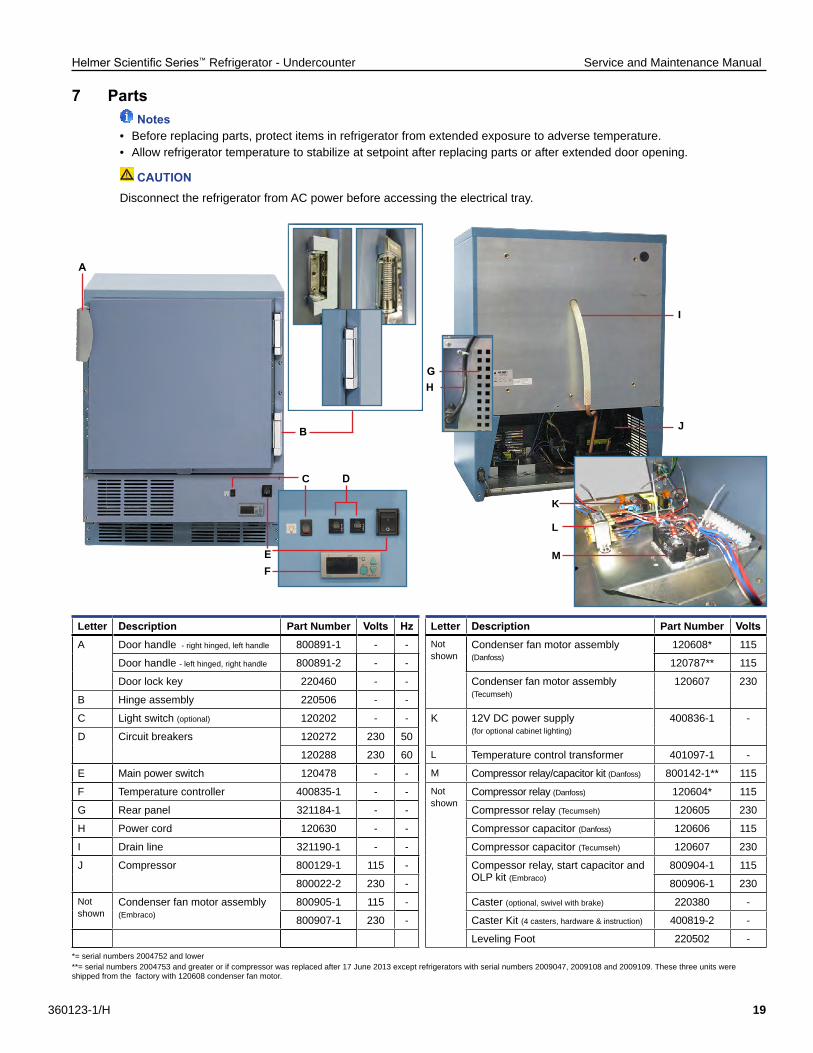
7 Parts Notes
• Before replacing parts, protect items in refrigerator from extended exposure to adverse temperature.• Allow refrigerator temperature to stabilize at setpoint after replacing parts or after extended door opening.
CAUTIONDisconnect the refrigerator from AC power before accessing the electrical tray.
Letter Description Part Number Volts Hz Letter Description Part Number VoltsA Door handle - right hinged, left handle 800891-1 - - Not
shownCondenser fan motor assembly (Danfoss)
120608* 115
Door handle - left hinged, right handle 800891-2 - - 120787** 115
Door lock key 220460 - - Condenser fan motor assembly (Tecumseh)
120607 230
B Hinge assembly 220506 - -
C Light switch (optional) 120202 - - K 12V DC power supply (for optional cabinet lighting)
400836-1 -
D Circuit breakers 120272 230 50
120288 230 60 L Temperature control transformer 401097-1 -
E Main power switch 120478 - - M Compressor relay/capacitor kit (Danfoss) 800142-1** 115
F Temperature controller 400835-1 - - Not shown
Compressor relay (Danfoss) 120604* 115
G Rear panel 321184-1 - - Compressor relay (Tecumseh) 120605 230
H Power cord 120630 - - Compressor capacitor (Danfoss) 120606 115
I Drain line 321190-1 - - Compressor capacitor (Tecumseh) 120607 230
J Compressor 800129-1 115 - Compessor relay, start capacitor and OLP kit (Embraco)
800904-1 115
800022-2 230 - 800906-1 230Not shown
Condenser fan motor assembly (Embraco)
800905-1 115 - Caster (optional, swivel with brake) 220380 -
800907-1 230 - Caster Kit (4 casters, hardware & instruction) 400819-2 -
Leveling Foot 220502 -*= serial numbers 2004752 and lower **= serial numbers 2004753 and greater or if compressor was replaced after 17 June 2013 except refrigerators with serial numbers 2009047, 2009108 and 2009109. These three units were shipped from the factory with 120608 condenser fan motor.
A
B
E
C D
G
FM
L
K
J
I
H
Helmer Scientific Series™ Refrigerator - Undercounter Service and Maintenance Manual
360123-1/H 20
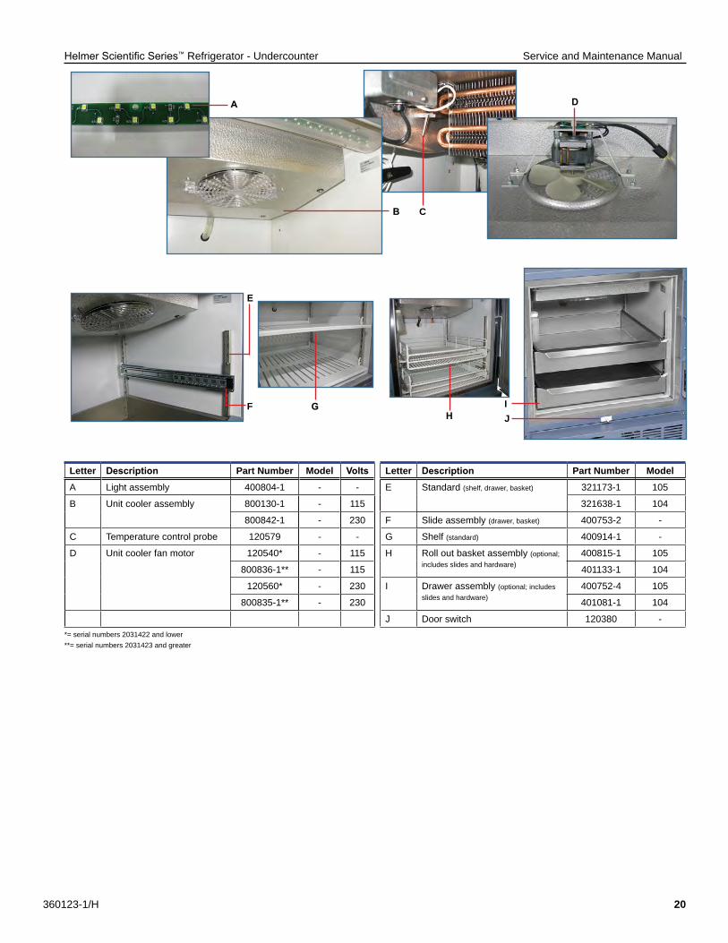
Letter Description Part Number Model Volts Letter Description Part Number ModelA Light assembly 400804-1 - - E Standard (shelf, drawer, basket) 321173-1 105
B Unit cooler assembly 800130-1 - 115 321638-1 104
800842-1 - 230 F Slide assembly (drawer, basket) 400753-2 -
C Temperature control probe 120579 - - G Shelf (standard) 400914-1 -
D Unit cooler fan motor 120540* - 115 H Roll out basket assembly (optional; includes slides and hardware)
400815-1 105
800836-1** - 115 401133-1 104
120560* - 230 I Drawer assembly (optional; includes slides and hardware)
400752-4 105
800835-1** - 230 401081-1 104
J Door switch 120380 -*= serial numbers 2031422 and lower **= serial numbers 2031423 and greater
A
B C
D
JI
HGF
E
Helmer Scientific Series™ Refrigerator - Undercounter Service and Maintenance Manual
360123-1/H 21
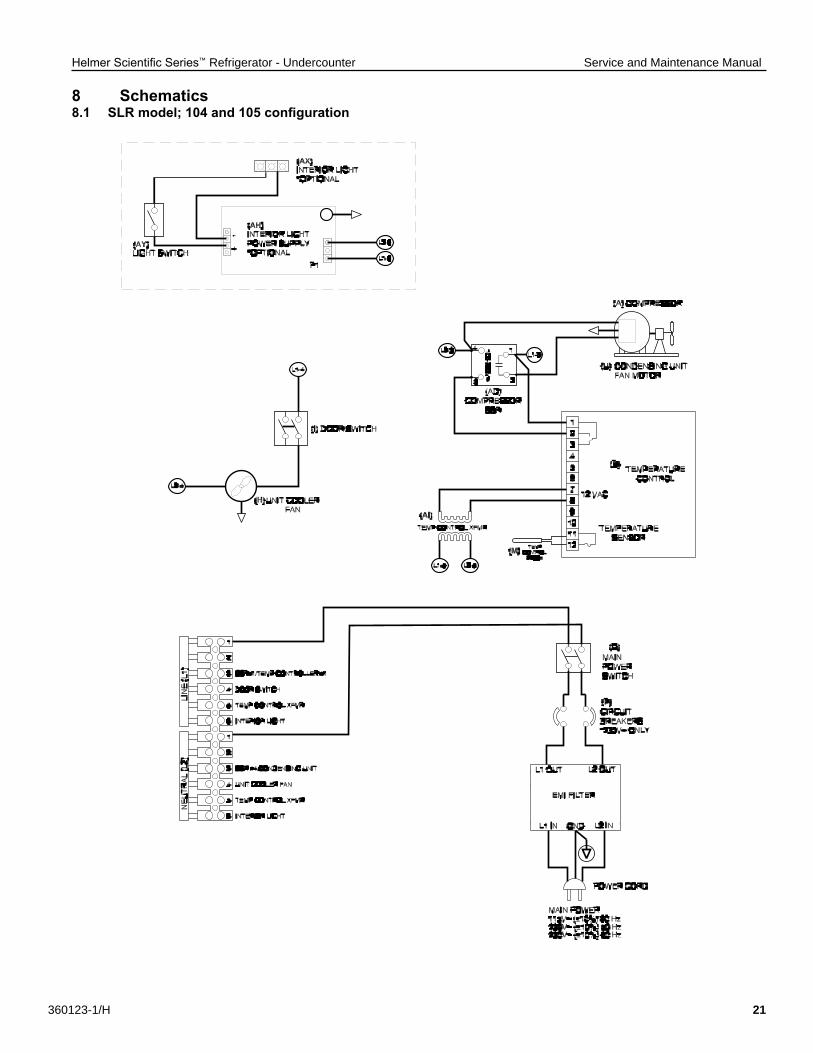
8 Schematics8.1 SLR model; 104 and 105 configuration
Helmer Scientific Series™ Refrigerator - Undercounter Service and Maintenance Manual
360123-1/H 22
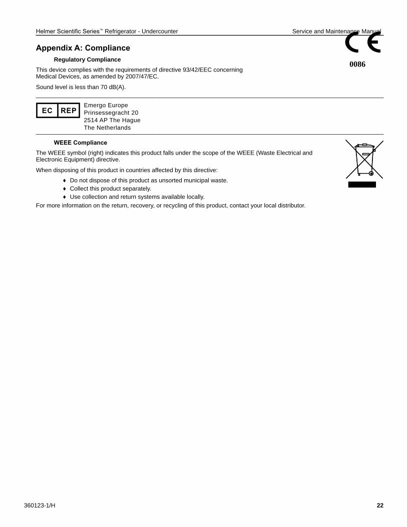
Appendix A: Compliance Regulatory Compliance
This device complies with the requirements of directive 93/42/EEC concerning Medical Devices, as amended by 2007/47/EC.
Sound level is less than 70 dB(A).
EC REPEmergo EuropePrinsessegracht 202514 AP The Hague The Netherlands
WEEE ComplianceThe WEEE symbol (right) indicates this product falls under the scope of the WEEE (Waste Electrical and Electronic Equipment) directive.
When disposing of this product in countries affected by this directive:
♦ Do not dispose of this product as unsorted municipal waste. ♦ Collect this product separately. ♦ Use collection and return systems available locally.
For more information on the return, recovery, or recycling of this product, contact your local distributor.
0086
Helmer Scientific Series™ Refrigerator - Undercounter Service and Maintenance Manual
360123-1/H 23
Appendix B: WarrantyRel.i™ Product Warranty USA and Canada
For technical service needs, please contact Helmer at 800-743-5637 or www.helmerinc.com. Have the model and serial number available when calling.
Rapid ResolutionWhen a warranty issue arises it is our desire to respond quickly and appropriately. The service department at Helmer is there for you. Helmer will oversee the handling of your warranty service from start to finish. Therefore, Helmer must give advance authorization for all service calls and/or parts needs relating to a warranty issue. Any repeat service calls must also be authorized as well. This allows for proper diagnosis and action. Helmer will not be responsible for charges incurred for service calls made by third parties prior to authorization from Helmer. Helmer retains the right to replace any product in lieu of servicing it in the field.
CompressorFor the warranty period listed below, Helmer will supply the refrigeration compressor, if it is determined to be defective, at no charge, including freight. Helmer will not be liable for installation, refrigerant, or miscellaneous charges required to install the compressor beyond the first year of the warranty period.
♦ Scientific Series model compressor warranty period is five (5) years.Parts
For a period of two (2) years, Helmer will supply at no charge, including freight, any part that fails due to defects in material or workmanship under normal use, with the exception of expendable items. Expendable items such as glass, filters, light bulbs, and door gaskets are excluded from this warranty coverage. Inspection of defective parts by Helmer will be final in determining warranty status. Warranty procedures must be followed in all events.
LaborFor a period of one (1) year, Helmer will cover repair labor costs (including travel) and the cost of refrigerant and supplies necessary to perform authorized repairs. Repair service must be performed by an authorized Helmer service agency following the authorization process detailed above. Alternatively, your facility’s staff may work with a Helmer technician to make repairs. Labor costs for repairs made by unauthorized service personnel, or without the assistance of a Helmer technician, will be the responsibility of the end user.
Additional Warranty InformationThe time periods set forth above begin two (2) weeks after the original date of shipment from Helmer. Warranty procedures set forth above must be followed in all events.
THERE ARE NO WARRANTIES WHICH EXTEND BEYOND THE DESCRIPTION ON THE FACE HEREOF. THIS WARRANTY IS EXCLUSIVE AND IN LIEU OF ALL OTHER WARRANTIES, EXPRESS OR IMPLIED, INCLUDING WITHOUT LIMITATION ANY WARRANTY OF MERCHANTABILITY OR FITNESS FOR A PARTICULAR PURPOSE. NO WARRANTIES OF MERCHANTABILITY OR FITNESS FOR PARTICULAR PURPOSE SHALL APPLY.
THE LIABILITY, IF ANY, OF HELMER FOR DIRECT DAMAGES WHETHER ARISING FROM A BREACH OF ANY SALES AGREEMENT, BREACH OF WARRANTY, NEGLIGENCE, OR INDEMNITY, STRICT LIABILITY OR OTHER TORT, OR OTHERWISE WITH RESPECT TO THE GOODS OR ANY SERVICES IS LIMITED TO AN AMOUNT NOT TO EXCEED THE PRICE OF THE PARTICULAR GOODS OR SERVICES GIVING RISE TO THE LIABILITY. IN NO EVENT SHALL HELMER BE LIABLE FOR ANY INDIRECT, INCIDENTAL, CONSEQUENTIAL, OR SPECIAL DAMAGES, INCLUDING WITHOUT LIMITATION DAMAGES RELATED TO LOST REVENUES OR PROFITS, OR LOSS OF PRODUCTS.
This warranty does not cover damages caused in transit, during installation by accident, misuse, fire, flood, or acts of God. Further, this warranty will not be valid if Helmer determines that the failure was caused by a lack of performing recommended equipment maintenance (per Helmer manual) or by using the product in a manner other than for its intended use. Installation and calibration are not covered under this warranty agreement.
Outside of USA and CanadaConsult your local distributor for warranty information.
END OF MANUAL
Helmer Scientific Series™ Refrigerator - Undercounter Service and Maintenance Manual
360123-1/H 24
Notes
Helmer Scientific14400 Bergen Boulevard, Noblesville, IN 46060 USA
Copyright © 2017 Helmer, Inc. 360123-1/H