Embed Size (px)
Citation preview

MANUAL – INSTALLATION + SERVICE
Underfloor Fan Powered Booster & Terminal Unit
v100 – Issue Date: 11/02/18© 2018 Price Industries Limited. All rights reserved.
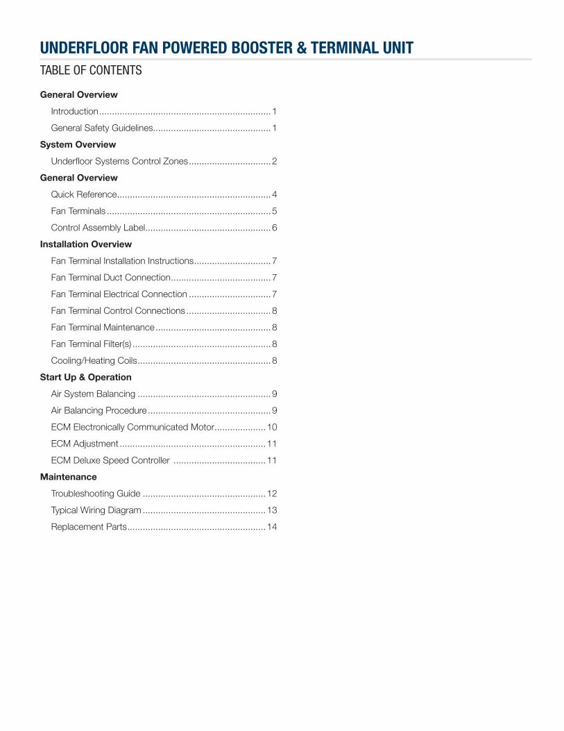
UNDERFLOOR FAN POWERED BOOSTER & TERMINAL UNIT TABLE OF CONTENTS
General Overview
Introduction ...................................................................1
General Safety Guidelines..............................................1
System Overview
Underfloor Systems Control Zones ................................2
General Overview
Quick Reference ............................................................4
Fan Terminals ................................................................5
Control Assembly Label .................................................6
Installation Overview
Fan Terminal Installation Instructions ..............................7
Fan Terminal Duct Connection .......................................7
Fan Terminal Electrical Connection ................................7
Fan Terminal Control Connections .................................8
Fan Terminal Maintenance .............................................8
Fan Terminal Filter(s) ......................................................8
Cooling/Heating Coils ....................................................8
Start Up & Operation
Air System Balancing ....................................................9
Air Balancing Procedure ................................................9
ECM Electronically Communicated Motor ....................10
ECM Adjustment .........................................................11
ECM Deluxe Speed Controller ....................................11
Maintenance
Troubleshooting Guide ................................................12
Typical Wiring Diagram ................................................13
Replacement Parts ......................................................14
1priceindustries.com | UNDERFLOOR FAN POWERED BOOSTER & TERMINAL UNIT - Manual
UNDERFLOOR FAN POWERED BOOSTER & TERMINAL UNIT GENERAL OVERVIEW
IntroductionIn this manual, you will find technical descriptions and diagrams of underfloor system components along with their installation instructions. Practical guidelines and recommendations are also provided. If more information is required about this equipment, please contact an Price sales representative.
General Safety GuidelinesThis document is intended for use by owner-authorized operating/service personnel who are expected to possess the required training to enable them to perform their tasks properly and safely. This individual must have read and understood this document and any referenced materials prior to performing any task on this equipment. Also, it is essential that this individual be familiar with and comply with all applicable governmental standards and regulations pertaining to the task in question. This individual must also verify that installation and connections comply with local building codes. It is the obligation and responsibility of the operating/service personnel to identify and recognize these inherent hazards, protect themselves, and proceed safely in completing their tasks. Failure to comply with any of these requirements could result in severe personal injury or death to themselves and people at the site, as well as serious damage to the equipment and the property in which it is situated.
The equipment discussed in this manual is relatively complicated apparatus and must be handled with the necessary precautions. Individuals may be exposed to certain components or conditions such as refrigerants, oils, materials under pressure, rotating components, and both high and low voltage during installation, operation, maintenance or service of this equipment. If misued or mishandled, each item has the potential to cause bodily injury or death.
2 UNDERFLOOR FAN POWERED BOOSTER & TERMINAL UNIT - Manual | priceindustries.com
UNDERFLOOR FAN POWERED BOOSTER & TERMINAL UNIT SYSTEM OVERVIEW
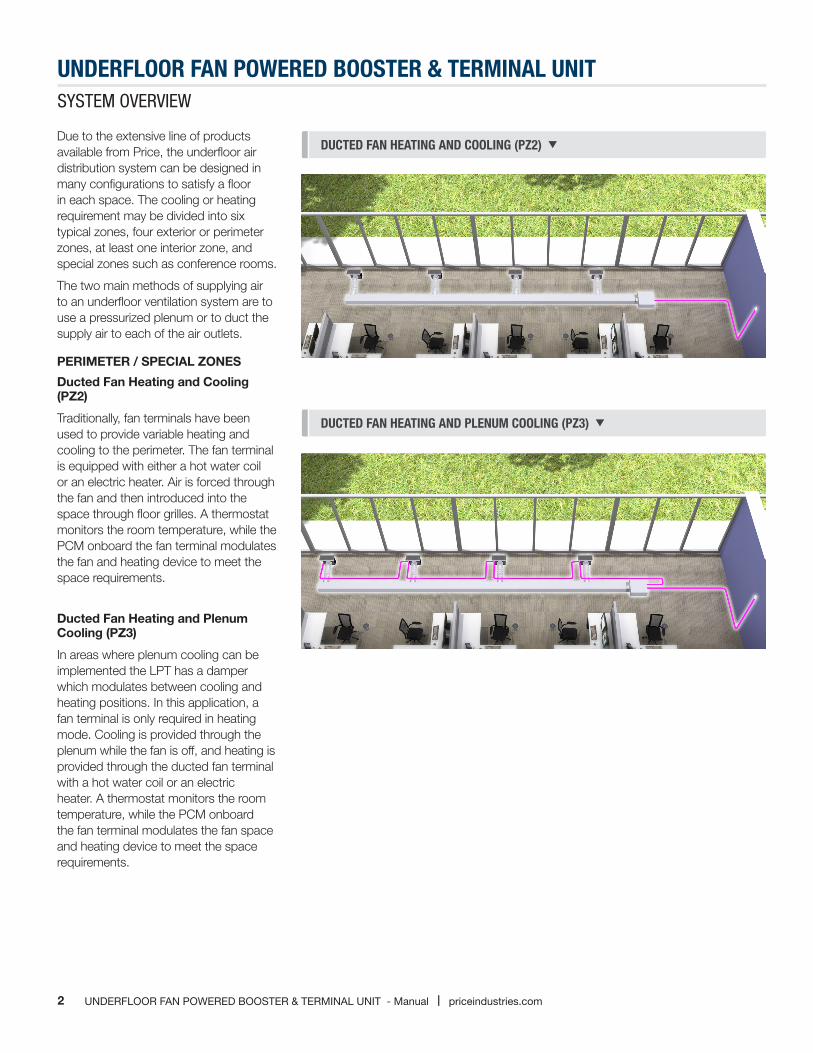
Due to the extensive line of products available from Price, the underfloor air distribution system can be designed in many configurations to satisfy a floor in each space. The cooling or heating requirement may be divided into six typical zones, four exterior or perimeter zones, at least one interior zone, and special zones such as conference rooms.
The two main methods of supplying air to an underfloor ventilation system are to use a pressurized plenum or to duct the supply air to each of the air outlets.
PERIMETER / SPECIAL ZONES
Ducted Fan Heating and Cooling (PZ2)
Traditionally, fan terminals have been used to provide variable heating and cooling to the perimeter. The fan terminal is equipped with either a hot water coil or an electric heater. Air is forced through the fan and then introduced into the space through floor grilles. A thermostat monitors the room temperature, while the PCM onboard the fan terminal modulates the fan and heating device to meet the space requirements.
Ducted Fan Heating and Plenum Cooling (PZ3)
In areas where plenum cooling can be implemented the LPT has a damper which modulates between cooling and heating positions. In this application, a fan terminal is only required in heating mode. Cooling is provided through the plenum while the fan is off, and heating is provided through the ducted fan terminal with a hot water coil or an electric heater. A thermostat monitors the room temperature, while the PCM onboard the fan terminal modulates the fan space and heating device to meet the space requirements.
DUCTED FAN HEATING AND COOLING (PZ2)
DUCTED FAN HEATING AND PLENUM COOLING (PZ3)

3priceindustries.com | UNDERFLOOR FAN POWERED BOOSTER & TERMINAL UNIT - Manual
UNDERFLOOR FAN POWERED BOOSTER & TERMINAL UNIT SYSTEM OVERVIEW
SUB-PLENUM COOLING ONLY: VARIABLE VOLUME (SZ1) Sub-plenum Cooling Only: Variable Volume (SZ1)
This control zone is formed using fixed damper position modular floor diffusers. The pressurized plenum for the space is divided from the rest of the floor plate. This sub-plenum is pressurized by a fan terminal. A thermostat monitors the room temperature and occupancy, while the PCM adjusts the fan to meet the cooling requirement of the space. This strategy is useful for rooms with large temperature swings and higher occupancy, versus smaller break-out style conference spaces.
4 UNDERFLOOR FAN POWERED BOOSTER & TERMINAL UNIT - Manual | priceindustries.com
UNDERFLOOR FAN POWERED BOOSTER & TERMINAL UNIT GENERAL OVERVIEW
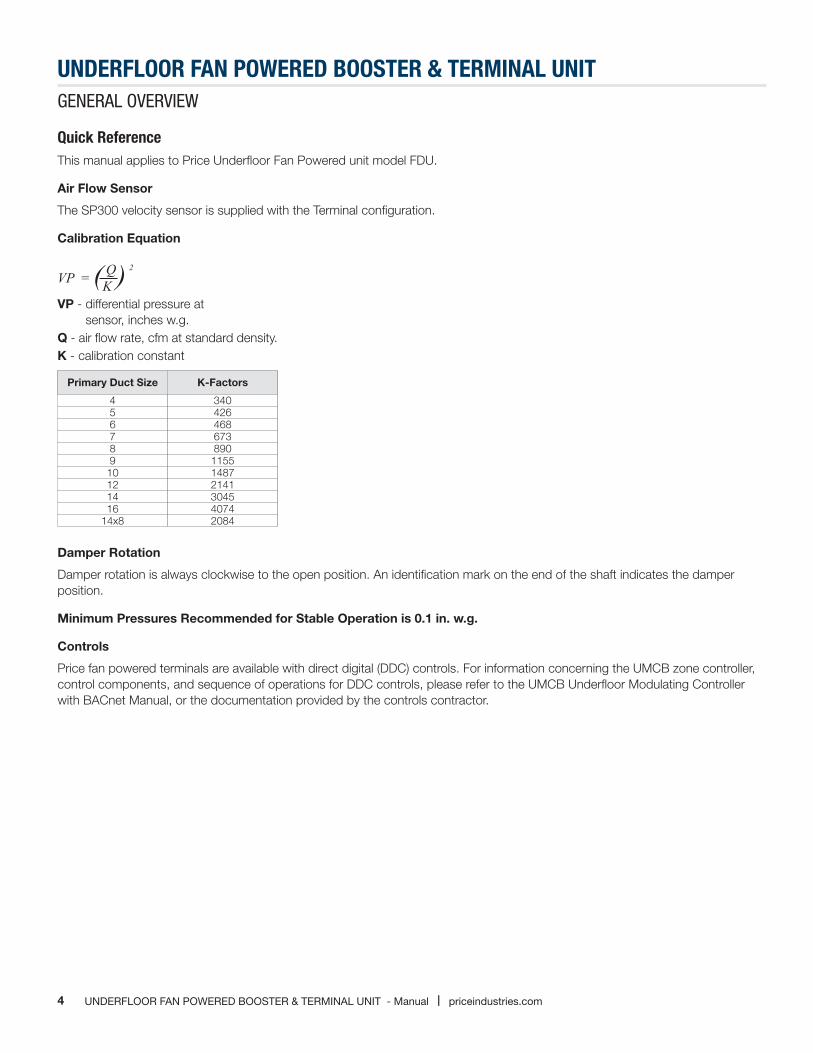
Quick ReferenceThis manual applies to Price Underfloor Fan Powered unit model FDU.
Air Flow Sensor
The SP300 velocity sensor is supplied with the Terminal configuration.
Calibration Equation
VP - differential pressure at sensor, inches w.g.
Q - air flow rate, cfm at standard density.K - calibration constant
( ) K2
VP = Q
Primary Duct Size K-Factors
4 3405 4266 4687 6738 8909 115510 148712 214114 304516 4074
14x8 2084
Damper Rotation
Damper rotation is always clockwise to the open position. An identification mark on the end of the shaft indicates the damper position.
Minimum Pressures Recommended for Stable Operation is 0.1 in. w.g.
Controls
Price fan powered terminals are available with direct digital (DDC) controls. For information concerning the UMCB zone controller, control components, and sequence of operations for DDC controls, please refer to the UMCB Underfloor Modulating Controller with BACnet Manual, or the documentation provided by the controls contractor.

5priceindustries.com | UNDERFLOOR FAN POWERED BOOSTER & TERMINAL UNIT - Manual
UNDERFLOOR FAN POWERED BOOSTER & TERMINAL UNIT GENERAL OVERVIEW
Fan TerminalsAn optional metal control cover may be provided to protect the terminal unit control components. The protective cover is removable with two sheet metal screws.
CAUTION:
1. Fan Powered Terminal Units are not intended for use as temporary heat or ventilation sources during building construction. The terminal units are not designed nor equipped to operate in a dusty construction environment. Recirculating fan wheels can become coated in construction dust, resulting in an unbalanced wheel. This in turn can contribute to reduced motor life. Inlet air filters, if supplied, would provide little protection as they would quickly become plugged with construction dust.
2. A Fan Powered Terminal Unit should never be operated if the downstream duct work has not been installed. A minimum of 0.10 inches W.G. downstream static pressure resistance is required for safe operation of the recirculating fan motor.
NOTE: Operating in unauthorized conditions, as outlined above, will void the Price warranty.
Receiving Inspection
All Price Fan Powered Terminal Units are inspected before shipment. After unpacking the assembly, check it for damage. If any damage to the products is found, report it immediately to the delivery carrier. During unpacking and installation, do not handle the unit by the inlet velocity sensor. Caution is required when unpacking the fan powered units with electric coils so as not to damage the elements.
Ensure that all packing material is removed from the inside of the unit, especially around the blower wheel and coil section.
WARNING: Do not adjust the control components.
6 UNDERFLOOR FAN POWERED BOOSTER & TERMINAL UNIT - Manual | priceindustries.com
UNDERFLOOR FAN POWERED BOOSTER & TERMINAL UNIT GENERAL OVERVIEW
1462263
1290 Barrow Ind. ParkwayWinder, GA 30680-5704Phone: (678) 425-6640Fax: (678) 425-6659 VAV-101
PRICE RESEARCH CENTER
Configuration = B; Fan Volume = 300 CFM
1 FDU-1-1 20 FLD /6000
FG50 ECM115 Volts
0 CFM 0 CFM
4P-RE,HWC,CWC
LH-HEAT, 1H, LH-COOL, 1C, GALV DC, SB-E
0 L/S 0 L/S
REPRINTED
REPRINTED
O1462263000100010001Printed on 10/08/2018
1462263 1 FDU-1-1 20
1462263 1 FDU-1-1 20
Min.0 CFM Max.0 CFMMin. 0 L/S Max. 0 L/S
FDU-1-X
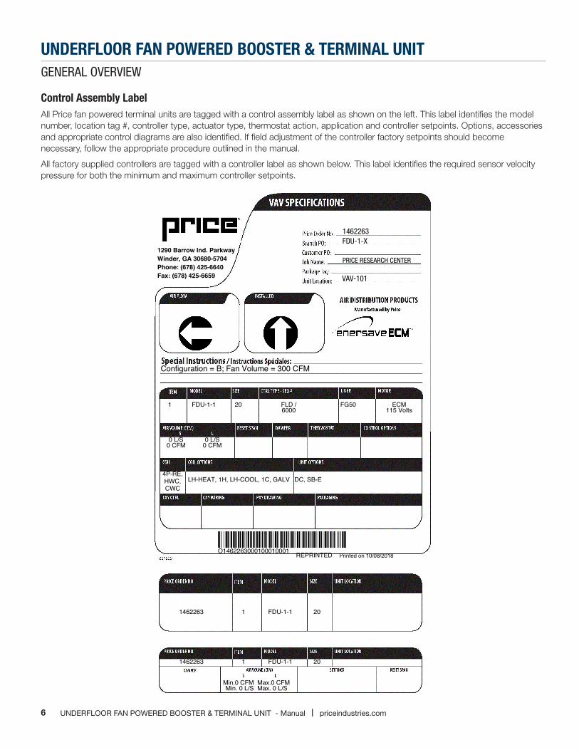
Control Assembly LabelAll Price fan powered terminal units are tagged with a control assembly label as shown on the left. This label identifies the model number, location tag #, controller type, actuator type, thermostat action, application and controller setpoints. Options, accessories and appropriate control diagrams are also identified. If field adjustment of the controller factory setpoints should become necessary, follow the appropriate procedure outlined in the manual.
All factory supplied controllers are tagged with a controller label as shown below. This label identifies the required sensor velocity pressure for both the minimum and maximum controller setpoints.
7priceindustries.com | UNDERFLOOR FAN POWERED BOOSTER & TERMINAL UNIT - Manual
UNDERFLOOR FAN POWERED BOOSTER & TERMINAL UNIT INSTALLATION OVERVIEW
Fan Terminal Installation InstructionsMounting The Unit
1. Price Fan Powered Terminal Units are designed to be mounted in the direction indicated by the Control Assembly Label found on the protective shroud.
2. Mount the unit directly on the sub-floor, beneath the raised floor. Ensure the area where the unit is to go is clear of cables, wires, etc.
3. Position the unit so that there is no interference with the raised floor support members.
4. Install the unit in a location that allows free access to the unit as well as all control components.
5. Ensure main power to the terminal and electrical coil has been disconnected prior to performing any electrical work or inspection of the circuitry.
WARNING: Do not tamper with control components.
Fan Terminal Duct Connection1. To prevent excessive air leakage, all cleat joints should be sealed with an approved duct sealer. This applies to all accessory
connections as well as the basic fan box.
2. Holes that are drilled in the duct for testing or balancing purposes are to be sealed with duct tape or duct sealer.
3. A minimum of 0.10 inches W.G. downstream static pressure is required to prevent overheating of the fan motor.
Fan Terminal Electrical Connection1. All field wiring is to be in accordance with the National Electrical Code ANSI/NFPA No. 70 or the Canadian Electrical Code ,
Part 1, CSA Standard C 22.1 and local codes and standards.
2. Refer to the product identification label on each unit for information to determine the field wire size.
CAUTION: Check voltage requirements prior to power supply connection. Refer to the electrical label located near the electrical control box and also refer to the schematic drawing provided on the underside of the electrical control box cover.
3. If upon energizing the electric motor(s), excessive noise is apparent, shut down the unit. Determine the cause by checking for packing materials, etc. and re-energize after corrective action has been taken.
4. If an Electric Reheat Coil has been supplied, refer to the electrical schematic which is permanently affixed to the topside of the electrical control cabinet cover, prior to hook-up.
CAUTION: Check the voltage requirements to ensure proper voltage supply is used
8 UNDERFLOOR FAN POWERED BOOSTER & TERMINAL UNIT - Manual | priceindustries.com
UNDERFLOOR FAN POWERED BOOSTER & TERMINAL UNIT INSTALLATION OVERVIEW
Fan Terminal Control ConnectionsDigital
If controls have been factory mounted, a wiring diagram will be included with the unit indicating the factory mounted components. For field wiring of room sensors and other accessories, refer to the Controls Contractor’s documentation for all wiring information.
Fan Terminal Maintenance1. Disconnect all incoming power before servicing the unit.
2. Price Fan Powered Terminal Units are supplied with permanently lubricated motors.
3. The blower and motor should be inspected annually for accumulation of dust and dirt. Clean as necessary.
4. To access blower and motor for servicing, remove the top access panel.
5. Motors are provided with thermal overload protection. If the motor overheats and trips the thermal overload, it will automatically reset after cooling down to a proper operating temperature.
6. If field amperage draw readings of the fan motor are required, measurements should be taken with a true RMS meter. Non-true RMS meters will not provide accurate reading due to alteration of the sine wave by the fan speed control. Refer to Page 7 for maximum motor operating amps.
Fan Terminal Filter(s)1. Filters, if supplied, should be replaced or removed after system start-up.
2. If filters are used beyond system start-up, they should be changed regularly to avoid excessive restriction of air flow. Frequency would depend on environment.
3. Contact your Price representative for details on replacement filter media
Cooling/Heating CoilsPrior to the water system start-up and balancing, the chilled/hot water systems should be flushed to clean out dirt and debris, which may have collected in the piping during construction.
During this procedure, all unit service valves must be in the closed position. This prevents foreign matter from entering the unit and clogging the valves and metering devices. Filters should be installed in the piping mains to prevent this material from entering the units during normal operation. During system filling, air venting from the unit is accomplished by the use of the standard manual air vent fitting installed on the coil. Manual air vent fitting: the screw should be turned counterclockwise no more than 1-1/2 turns to operate the air vent.
CAUTION: The air vent provided on the unit is not intended to replace the main system air vents and may not release air trapped in other parts of the system. Inspect the entire system for potential air traps and vent those areas as required, independently. In addition, some systems may require repeated venting over a period of time to properly eliminate air from the system.

9priceindustries.com | UNDERFLOOR FAN POWERED BOOSTER & TERMINAL UNIT - Manual
UNDERFLOOR FAN POWERED BOOSTER & TERMINAL UNIT START UP & OPERATION
Air System Balancing
Overview
All ductwork must be complete and connected, and all grilles, filters, access doors and panels must be properly installed to establish actual system operating conditions BEFORE beginning air balancing operations. Each individual unit and attached ductwork is a unique system with its own operating characteristics. For this reason, air balancing is normally done by balance specialists who are familiar with all procedures required to properly establish air distribution and fan system operating conditions.
These procedures should not be attempted by unqualified personnel.
After the proper system operation is established, the actual unit air delivery and the actual fan motor amperage draw for each unit should be recorded in a convenient place for future reference such as the inspection, installation, & start-up check sheet, a copy of which is provided on the back of this manual. Contact the sales representative or the factory for additional copies of this sheet.
The manufacturer assumes no responsibility for undesirable system operation due to improper design, equipment or component selection, and/or installation of ductwork, grilles, and other field supplied components.
Air Balancing Procedure Before Air Balancing the terminal unit, the following general items should be verified.
1. The primary fan system is operating at the specified volume, static pressure, RPM and current.
2. Return filters (if supplied) are clean.
3. All balancing dampers are adjusted and locked. Dampers downstream of the terminal unit should be proportionally balanced.
4. Thermostats are calibrated and operational.
5. All duct work and connections are free from leaks.
6. Sufficient duct static pressure is available at the terminal primary air inlet.
7. All diffusers are installed and adjusted for the proper air pattern.
NOTE: Since fan powered terminals are typically operating within a pressurized plenum, all flooring tiles must be replaced prior to verifying outlet flows.
8. A fan powered terminal unit should never be operated if the downstream duct work has not been installed. A minimum downstream static pressure resistance of 0.1 in. w.g. is recommended.
9. If field adjustment of the primary air valve should be necessary, follow the appropriate calibration procedures for the controller type supplied with the unit. If DDC controls are supplied, refer to the control contractor’s documentation for calibration instructions.
10. Set the thermostat to full cooling. The fan should be on and the primary air valve (if present) at maximum air flow. Verify the air flow with the sensor tube or pitot tube traverse. Adjust if necessary.
11. The fan volume must be field adjusted with the fan speed controller. Fan curves (available at priceindustries.com) indicate the volume range of each size unit. Adjust the speed control until the desired air flow is measured at the outlet.
12. Set the thermostat to full heating. The fan should be on and the primary air valve (if present) at minimum flow. Verify the primary air volume with sensor taps or pitot tube traverse. Adjust if necessary.
13. Always set the fan volume at full cooling.
10 UNDERFLOOR FAN POWERED BOOSTER & TERMINAL UNIT - Manual | priceindustries.com
UNDERFLOOR FAN POWERED BOOSTER & TERMINAL UNIT START UP & OPERATION
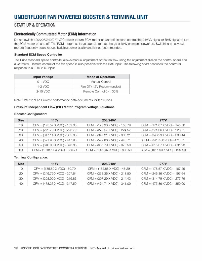
Electronically Commutated Motor (ECM) Information Do not switch 120/208/240/277 VAC power to turn ECM motor on and off. Instead control the 24VAC signal or BAS signal to turn the ECM motor on and off. The ECM motor has large capacitors that charge quickly on mains power up. Switching on several motors frequently could reduce building power quality and is not recommended.
Standard ECM Speed Controller
The Price standard speed controller allows manual adjustment of the fan flow using the adjustment dial on the control board and a voltmeter. Remote control of the fan speed is also possible with the BAS input. The following chart describes the controller response to a 0-10 VDC input.
Input Voltage Mode of Operation
0-1 VDC Manual Control
1-2 VDC Fan Off (1.5V Recommended)
2-10 VDC Remote Control 0 - 100%
Note: Refer to “Fan Curves” performance data documents for fan curves.
Pressure Independent Flow (PIF) Motor Program Voltage Equations
Booster Configuration:
Size 115V 208/240V 277V
10 CFM = (175.57 X VDC) - 159.00 CFM = (173.93 X VDC) - 153.79 CFM = (171.07 X VDC) - 145.50
20 CFM = (272.79 X VDC) - 228.79 CFM = (272.57 X VDC) - 224.57 CFM = (271.36 X VDC) - 220.21
30 CFM = (347.14 X VDC) - 305.86 CFM = (347.21 X VDC) - 306.21 CFM = (346.29 X VDC) - 300.14
40 CFM = (521.93 X VDC) - 447.93 CFM = (522.86 X VDC) - 445.71 CFM = (526.5 X VDC) - 471.07
50 CFM = (640.00 X VDC) - 378.86 CFM = (636.79 X VDC) - 373.50 CFM = (615.07 X VDC) - 331.93
60 CFM = (1018.14 X VDC) - 885.71 CFM = (1029.07 X VDC) - 893.50 CFM = (1015.93 X VDC) - 897.93
Terminal Configuration:
Size 115V 208/240V 277V
10 CFM = (155.50 X VDC) - 50.79 CFM = (152.86 X VDC) - 45.29 CFM = (178.57 X VDC) - 167.29
20 CFM = (249.79 X VDC) - 207.64 CFM = (253.36 X VDC) - 211.50 CFM = (246.36 X VDC) - 197.64
30 CFM = (298.00 X VDC) - 216.86 CFM = (297.29 X VDC) - 214.43 CFM = (314.79 X VDC) - 277.79
40 CFM = (478.36 X VDC) - 347.50 CFM = (474.71 X VDC) - 341.00 CFM = (475.86 X VDC) - 350.00
11priceindustries.com | UNDERFLOOR FAN POWERED BOOSTER & TERMINAL UNIT - Manual
UNDERFLOOR FAN POWERED BOOSTER & TERMINAL UNIT START UP & OPERATION
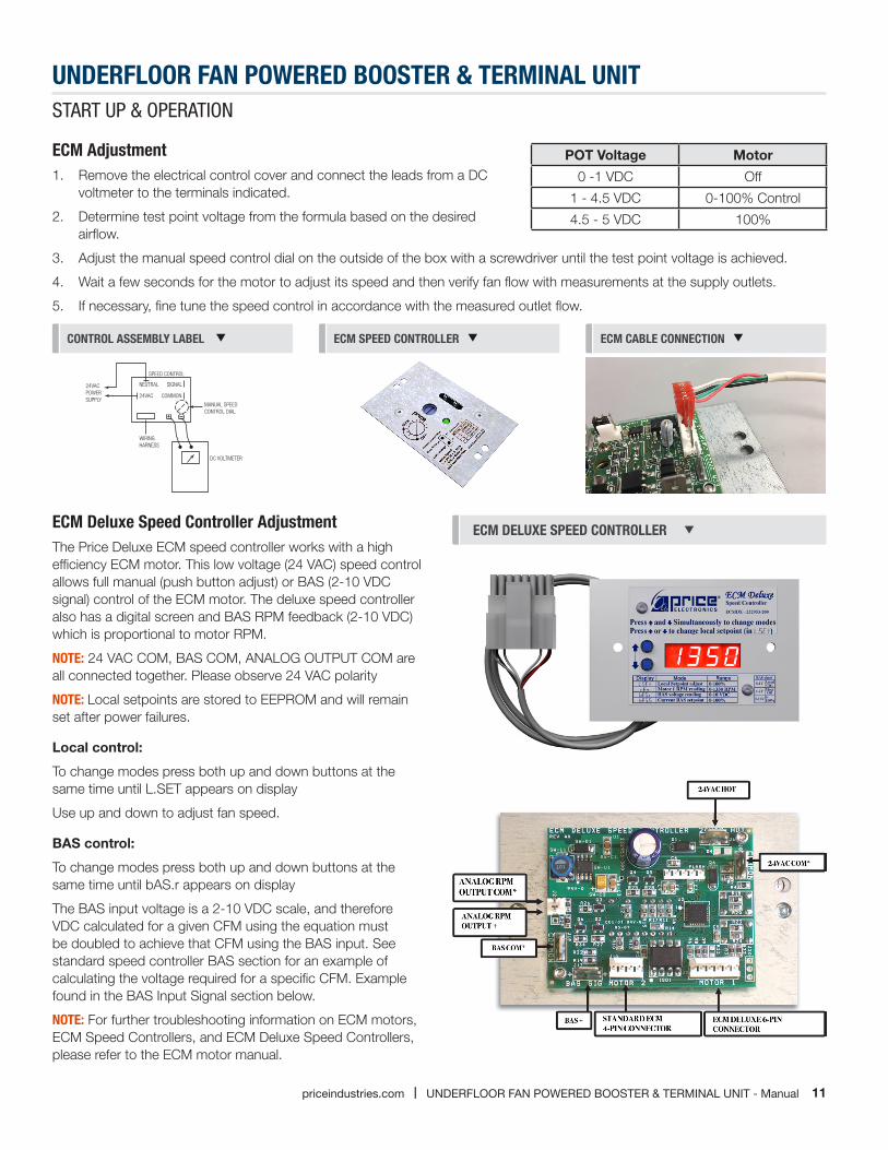
ECM Adjustment 1. Remove the electrical control cover and connect the leads from a DC
voltmeter to the terminals indicated.
2. Determine test point voltage from the formula based on the desired airflow.
3. Adjust the manual speed control dial on the outside of the box with a screwdriver until the test point voltage is achieved.
4. Wait a few seconds for the motor to adjust its speed and then verify fan flow with measurements at the supply outlets.
5. If necessary, fine tune the speed control in accordance with the measured outlet flow.
MANUAL SPEED CONTROL DIAL
DC VOLTMETER
WIRINGHARNESS
24VAC POWERSUPPLY
SPEED CONTROL
NEUTRAL SIGNAL
24VAC COMMON
CONTROL ASSEMBLY LABEL ECM SPEED CONTROLLER ECM CABLE CONNECTION
ECM Deluxe Speed Controller Adjustment The Price Deluxe ECM speed controller works with a high efficiency ECM motor. This low voltage (24 VAC) speed control allows full manual (push button adjust) or BAS (2-10 VDC signal) control of the ECM motor. The deluxe speed controller also has a digital screen and BAS RPM feedback (2-10 VDC) which is proportional to motor RPM.
NOTE: 24 VAC COM, BAS COM, ANALOG OUTPUT COM are all connected together. Please observe 24 VAC polarity
NOTE: Local setpoints are stored to EEPROM and will remain set after power failures.
Local control:
To change modes press both up and down buttons at the same time until L.SET appears on display
Use up and down to adjust fan speed.
BAS control:
To change modes press both up and down buttons at the same time until bAS.r appears on display
The BAS input voltage is a 2-10 VDC scale, and therefore VDC calculated for a given CFM using the equation must be doubled to achieve that CFM using the BAS input. See standard speed controller BAS section for an example of calculating the voltage required for a specific CFM. Example found in the BAS Input Signal section below.
NOTE: For further troubleshooting information on ECM motors, ECM Speed Controllers, and ECM Deluxe Speed Controllers, please refer to the ECM motor manual.
ECM DELUXE SPEED CONTROLLER
POT Voltage Motor
0 -1 VDC Off
1 - 4.5 VDC 0-100% Control
4.5 - 5 VDC 100%
12 UNDERFLOOR FAN POWERED BOOSTER & TERMINAL UNIT - Manual | priceindustries.com
UNDERFLOOR FAN POWERED BOOSTER & TERMINAL UNIT MAINTENANcE
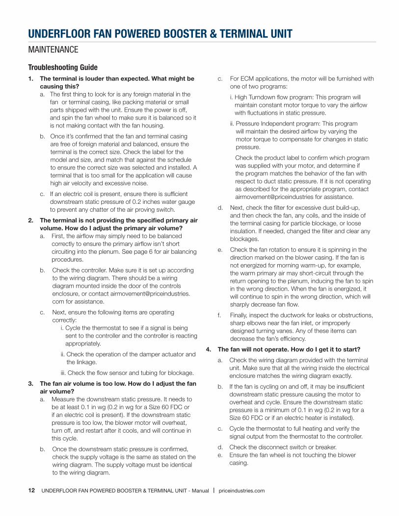
Troubleshooting Guide1. The terminal is louder than expected. What might be
causing this? a. The first thing to look for is any foreign material in the
fan or terminal casing, like packing material or small parts shipped with the unit. Ensure the power is off, and spin the fan wheel to make sure it is balanced so it is not making contact with the fan housing.
b. Once it’s confirmed that the fan and terminal casing are free of foreign material and balanced, ensure the terminal is the correct size. Check the label for the model and size, and match that against the schedule to ensure the correct size was selected and installed. A terminal that is too small for the application will cause high air velocity and excessive noise.
c. If an electric coil is present, ensure there is sufficient downstream static pressure of 0.2 inches water gauge to prevent any chatter of the air proving switch.
2. The terminal is not providing the specified primary air volume. How do I adjust the primary air volume? a. First, the airflow may simply need to be balanced
correctly to ensure the primary airflow isn’t short circuiting into the plenum. See page 6 for air balancing procedures.
b. Check the controller. Make sure it is set up according to the wiring diagram. There should be a wiring diagram mounted inside the door of the controls enclosure, or contact [email protected] for assistance.
c. Next, ensure the following items are operating correctly: i. Cycle the thermostat to see if a signal is being
sent to the controller and the controller is reacting appropriately.
ii. Check the operation of the damper actuator and the linkage.
iii. Check the flow sensor and tubing for blockage.
3. The fan air volume is too low. How do I adjust the fan air volume? a. Measure the downstream static pressure. It needs to
be at least 0.1 in wg (0.2 in wg for a Size 60 FDC or if an electric coil is present). If the downstream static pressure is too low, the blower motor will overheat, turn off, and restart after it cools, and will continue in this cycle.
b. Once the downstream static pressure is confirmed, check the supply voltage is the same as stated on the wiring diagram. The supply voltage must be identical to the wiring diagram.
c. For ECM applications, the motor will be furnished with one of two programs:
i. High Turndown flow program: This program will maintain constant motor torque to vary the airflow with fluctuations in static pressure.
ii. Pressure Independent program: This program will maintain the desired airflow by varying the motor torque to compensate for changes in static pressure.
Check the product label to confirm which program was supplied with your motor, and determine if the program matches the behavior of the fan with respect to duct static pressure. If it is not operating as described for the appropriate program, contact airmovement@priceindustries for assistance.
d. Next, check the filter for excessive dust build-up, and then check the fan, any coils, and the inside of the terminal casing for particle blockage, or loose insulation. If needed, changed the filter and clear any blockages.
e. Check the fan rotation to ensure it is spinning in the direction marked on the blower casing. If the fan is not energized for morning warm-up, for example, the warm primary air may short-circuit through the return opening to the plenum, inducing the fan to spin in the wrong direction. When the fan is energized, it will continue to spin in the wrong direction, which will sharply decrease fan flow.
f. Finally, inspect the ductwork for leaks or obstructions, sharp elbows near the fan inlet, or improperly designed turning vanes. Any of these items can decrease the fan’s efficiency.
4. The fan will not operate. How do I get it to start?
a. Check the wiring diagram provided with the terminal unit. Make sure that all the wiring inside the electrical enclosure matches the wiring diagram exactly.
b. If the fan is cycling on and off, it may be insufficient downstream static pressure causing the motor to overheat and cycle. Ensure the downstream static pressure is a minimum of 0.1 in wg (0.2 in wg for a Size 60 FDC or if an electric heater is installed).
c. Cycle the thermostat to full heating and verify the signal output from the thermostat to the controller.
d. Check the disconnect switch or breaker. e. Ensure the fan wheel is not touching the blower
casing.
13priceindustries.com | UNDERFLOOR FAN POWERED BOOSTER & TERMINAL UNIT - Manual
UNDERFLOOR FAN POWERED BOOSTER & TERMINAL UNIT MAINTENANcE
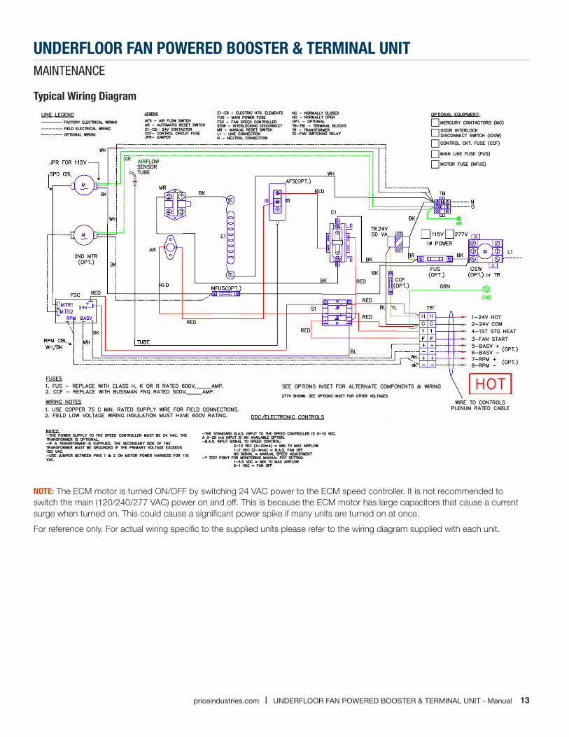
Typical Wiring Diagram
NOTE: The ECM motor is turned ON/OFF by switching 24 VAC power to the ECM speed controller. It is not recommended to switch the main (120/240/277 VAC) power on and off. This is because the ECM motor has large capacitors that cause a current surge when turned on. This could cause a significant power spike if many units are turned on at once.
For reference only. For actual wiring specific to the supplied units please refer to the wiring diagram supplied with each unit.
UNE LEGEND --- FACTORY ELEClRICAL WIRING ------ FIELD EL.EClRICAL WIRING ---- OPTIONAL WIRING
WH
AFS - AIR FLOW SWITCH AR - AUTOMATIC RESET SWITCH C1-C2- 24V CONTACTOR CCF- CONlROL CIRCUIT FUSE .PR- JJMPER
E1-E6 - EL.EClRIC HTG. ELEMENTS FUS - MAIN POWER FUSE FSC - FAN SPEED CONlROLLER IDSW - INTERLOCKING DISCONNECT MR - MANUAL RESET SWITCH L1 - LINE CONNECTION N - NEUlRAL CONNECTION
NC - NORMALLY CLOSED NO - NORMALLY OPEN OPT. - OPTIONAL TB-181 - TERMINAL BLOCKS 1R - lRANSFORMER S1-FAN SWITCHING RELAY
-----------------------------------------------------------------7 [GR
--AIRFL0;
---------------------------------------------------7
�� '1 i i
OPTIONAL EOVIPMENT· □ MERCURY CONTACTORS {MC) □ DOOR INTERLOCK DISCONNECT SWITCH {IDSW) □ CONTROL CKT. FUSE {CCF) □ MAIN LINE FUSE {FUS) □ MOTOR FUSE {MFUS)
' i
TUBE WH , AFS(OPT.)
BK i ' I
L ________ :-\
��
2ND MTR (OPT.)
RED
i ' WHi''
AR
L ____ ----- ---- ____ �,,
RED
E1
1. FUS - REPLACE WITH CLASS H, K OR R RATED 600V, __ AMP.2. CCF - REPLACE WITH BUSSMAN FNQ RATED 5O0V, __ AMP.
0 Cl
BK
BK BK RED
RED S1 B
RED
RED
CCF (OPT.)
YL
FUS (OPT.)
L1
GRN ..-----------u!S'l
----
GND
1-24V HOT2-24V COM4-1ST STG HEAT3-FAN START5-BASV + (OPT)6-BASV - .
7-RPM + (OPT.) 8-RPM -
SEE OPTIONS INSET FOR AL TERNA TE COMPONENTS & WIRING I HOT I 277V SHOVtN. SEE OPTIONS INSET FOR OTHER VOLTAGES
WIRING NOTES 1. USE COPPER 75 C MIN. RA TED SUPPLY WIRE FOR FIELD CONNECTIONS. 2. FIELD LOW VOLTAGE WIRING INSULATION MUST HAVE 6O0V RATING. DDC/ELECTRONIC CONTROLS
-THE POWER SUPPLY TO THE SPEED CONlROLLER MUST BE 24 VAC. THE lRANSFORMER IS OPTIONAL -IF A lRANSFORMER IS SUPPLIED, THE SECONDARY SIDE OF THE lRANSFORMER MUST BE GROUNDED IF THE PRIMARY VOLTAGE EXCEEDS 150 VAC. -USE JJMPER BETWEEN PINS 1 & 2 ON MOTOR POWER HARNESS FOR 115 VAC.
-THE STANDARD B.A.S. INPUT TO THE SPEED CONlROLLER IS 0-10 voe. A 0-20 mA INPUT IS AN AVAILABLE OPTION. -B.A.S. INPUT SIGNAL TO SPEED CONlROL:
2-10 voe (4-20mA) = MIN TO MAX AIRFLOW 1-2 voe (2-4mA) = B.A.S. FAN OFF NO SIGNAL = MANUAL SPEED ADJUSlMENT
-• TEST POINT FOR MONITORING MANUAL POT SETTING: 1-4.5 voe = MIN TO MAX AIRFLOW 0-1 voe • FAN OFF
WIRE TO CONTROLS PLENUM RATED CABLE

14 UNDERFLOOR FAN POWERED BOOSTER & TERMINAL UNIT - Manual | priceindustries.com
UNDERFLOOR FAN POWERED BOOSTER & TERMINAL UNIT MAINTENANcE
Replacement Parts
Component Part# Description
ECM Fan Motors
019178-006 120V/240V - 1/3 HP (FDU Size 10, 20)019179-006 277V - 1/3 HP (FDU Size 10, 20)019178-007 120V/240V - 1/2 HP (FDU Size 30, 50)019179-007 277V - 1/2 HP (FDU Size 30, 50)019178-008 120V/240V - 3/4 HP (FDU Size 40)019179-008 277V - 3/4 HP (FDU Size 40)
ECM Speed Controller232952-100 Standard Fan Speed Controller (All Sizes)232952-200 Deluxe Fan Speed Controller (All Sizes)
Blowers100186-011 FDU Size 10, 20100185-002 FDU Size 30, 50100185-003 FDU Size 40
Actuators 019917-001 FDU Terminal & Booster w/ ID (Sizes 10-40)Thermostats Reference UMCB Underfloor Modulating Controller with BACnet Manual5 mfd
Transformers019436-001 115V-24V, 50 VA Transformer019436-011 208V/240V-24V, 50 VA Transformer019439-001 277V-24V, 50 VA Transformer
Disconnect Switch019903-001 115V/277V Single Pole019903-003 240V Two Pole
Drain Pan Part# Reference (506274-XXX)
2 Pipe 1 or 2 Row 2 Pipe 3 or 4 Row 2 Pipe 5 or 6 RowGalvanized Stainless Steel Galvanized Stainless Steel Galvanized Stainless Steel
001 101 002 102 003 1034 Pipe 1/2 Cool - 1/2 Heat 4 Pipe 3/4 Cool - 1/2 Heat 4 Pipe 5/6 Cool - 1/2 Heat
Galvanized Stainless Steel Galvanized Stainless Steel Galvanized Stainless Steel004 104 005 105 006 106
Discharge Attenuator Part# Reference (506271-XXX)
Unit Size Configuration XXX10 STD BOX/EC 00120 STD BOX/EC 00230 STD BOX/EC 00340 STD BOX/EC 00450 STD BOX/EC/WC 00510 BOX W/ CWC 101
10/20 BOX W/ HWC(10), CWC/HWC (20) 10230 BOX W/ WC 10340 BOX W/ WC 104

This document contains the most current product information as of this printing. For the most up-to-date product information, please go to priceindustries.com
© 2018 Price Industries Limited. All rights reserved.