Embed Size (px)
Citation preview
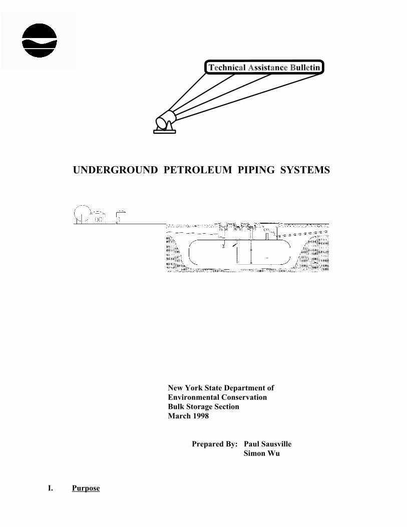
UNDERGROUND PETROLEUM PIPING SYSTEMS
New York State Department ofEnvironmental ConservationBulk Storage SectionMarch 1998
Prepared By: Paul Sausville Simon Wu
I. Purpose
2
This bulletin is written for those who are seeking technical information on installing newunderground petroleum pipelines. The bulletin addresses piping requirements covered by boththe New York State Petroleum Bulk Storage Regulations and the Federal Underground TankRegulations. It also discusses good engineering practices for preventing pipe leaks.
II. State Requirements
In December of 1985, the Department of Environmental Conservation establishedinstallation and equipment standards for all new underground storage facility pipelines. Thesestandards apply to petroleum storage systems where the combined capacity exceeds 1,100gallons, exempting on-premises heating oil tanks where the capacity is less than 1,100 gallons.
The standards, which are discussed in Section 614.14 of the Petroleum Bulk StorageRegulations, require that all new underground pipelines be as follows:
- pipes must be either constructed of;
• a non-corrodible material such as fiberglass reinforced plastic, nylon or engineered thermo-plastic, or
• metal such as steel with a cathodic protection system designed to protect it for 30 years.
- pipes may be in single or double-walled construction;
- access ports must be installed to permit tightness testing;
- installation must be in accordance with recognized engineering practices, and
- pipes and joints must be tightness tested before being covered and placed in use.
Other system requirements include impact valves at dispensers of motor fuel, overfillprevention equipment and a line leak detector for systems where the piping is operating underpressure. Suction systems must not be equipped with more than one check valve.
Each of these requirements is discussed in more detail below.
1. Pipe Materials and Designs
1.1 Double Walled vs Single Walled Pipe - Although the Department allows the use ofsingle-walled underground pipe, double-walled pipe is encouraged. Double-walled pipe not onlyprovides a higher level of environmental protection but because the space between the inner andouter wall can be readily checked for leaks, it provides the owner with the most efficient and cost
3
effective method of performing leak detection. With the advent of the flexible piping system,double-walled, piping with fewer joints has become easy and economical to install.
1.2 Flexible Piping Systems - Flexible pipe made of non-corrodible material complies withthe Department’s underground piping regulations. The pipe which can be purchased incontinuous rolls, typically several hundred feet in length, is installed in single long runs. Thereis no need for pipe fittings to extend the length of the line or change directions.
Most manufacturers offer pipe with nominal internal diameters between 1.5 and 2 inches. A few offer lines as small as 1 inch diameter (for heating oil applications) and as large as 3inches.
Flexible piping has several advantages. Although the cost per foot for flexible pipe ishigher than for rigid pipe, it has lower installation costs that may run as much as 70% below thecosts for rigid piping. A typical system requires only one or two days to install. Total costwhich include both the cost of pipe and installation is about the same as rigid piping. A secondadvantage is that because there are fewer joints and connections, fewer leaks occur over the lifeof the system. Double-walled flexible pipe has advantages over multi-jointed double-walledsystems where making tight joints for both the inner and outer wall can be difficult toaccomplish.
Although the installation of flexible pipe is generally simpler than that for rigid pipe,installers must be trained and the proper accessories must be used if environmental protection isto be maximized.
Mechanical leak detectors and continuous leak detectors seem to function adequately onpressurized flexible lines. Annual tightness tests can be readily performed, but the tester must beaware of the differences between the behavior of flexible pipelines and rigid pipelines. Suctionsystems may have some problems using flexible lines - check with manufacturer first.
Flexible pipe is constructed of polymeric compounds including nylon, polytetrafluoro-ethylene (PTFE or Teflon), high density polyethylene and proprietary composites. Pipes aregenerally strengthened with reinforcements of fiberglass, steel wire, or polyester braids. Mostare layered with fuel resistant lining on the inside, a stronger intermediate layer and an outerabrasion resistant covering. Because these materials do not corrode, cathodic protection as forsteel pipelines is not needed.
The elasticity of flexible pipe varies considerably from soft to somewhat rigid. Becauseof their inherent flexibility, they are sometimes pulled through a 4 inch flexible carrier pipe thatserves as both a protective sleeve that enables future pipe replacement without excavation and asa secondary containment chamber that can be monitored for leakage.
All of the flexible pipe is available with secondary containment. These secondarycontainment systems are not intended to hold the working pressure of a pipeline, but can convey
4
leaks to a sump area where the product can be detected.
One safety concern involves the connection of flexible pipelines to the dispenser. In theevent of a fire, the pipe could melt immediately below the emergency shut-off valve, increasingfire intensity. This problem can be mitigated by installing a fire rated flex connector or steelsegment of pipe down to the flexible piping, or by covering the pipeline in the sump areas withgravel.
Compatibility and permeability are important characteristics of any containment systems,but the terms are often confused. Compatibility is the ability of a material to retain its physicalproperties when exposed to another substance. Permeability is a measure of the amount of asubstance that migrates through a material over a given time period. For example, polyethyleneis compatible with petroleum products. This means that it does not significantly dissolve,degrade, or fall apart when in contact with petroleum products. However, polyethylene isrelatively permeable to petroleum products. This means that the liquid level in a tightly sealedpolyethylene container filled with gasoline would slowly decrease over time as gasolinemolecules migrate through the walls of the container.
To date, problems with flexible piping systems have been limited to fungal decay of firstgeneration polyurethane coated piping. The fungal decay is mostly cosmetic and does not causepipe failure, however, one manufacturer has changed the outer layer of pipe to polyethylene. Most manufacturers are now marketing third and fourth generation products. Problems withthese systems have been infrequent, and manufacturers have stood by their products. From anenvironmental protection standpoint, the performance of this technology to date has beenexcellent.
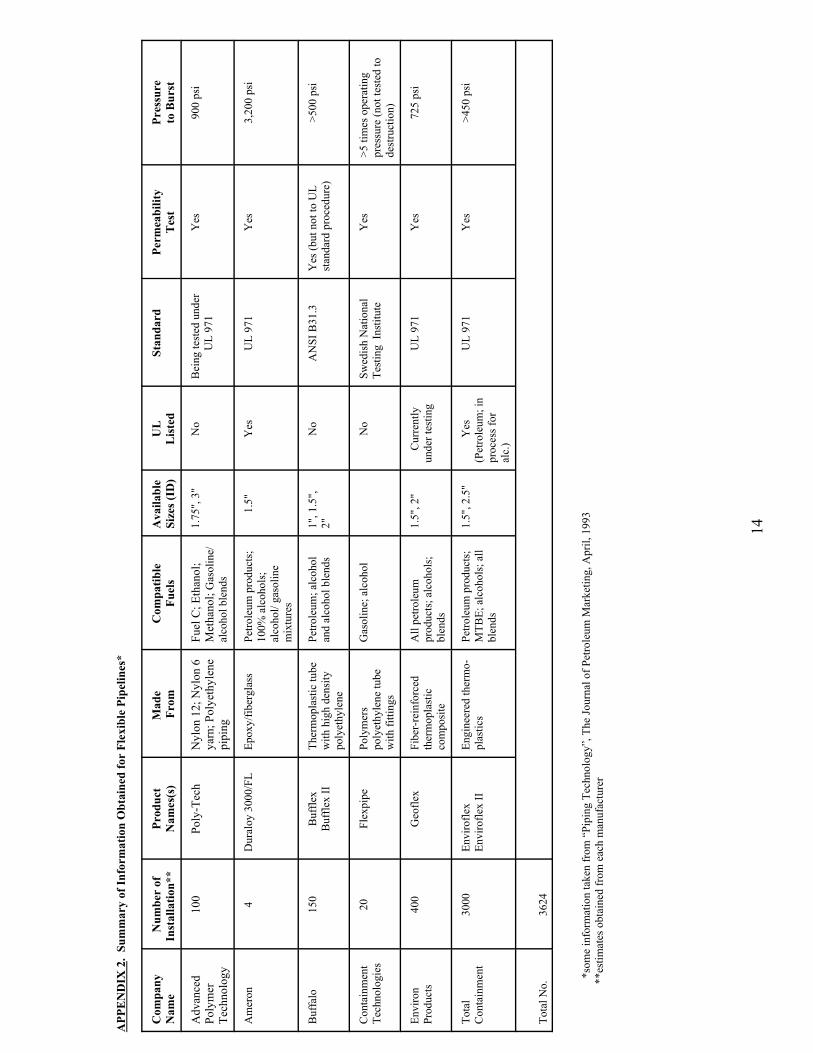
There are several manufacturers of flexible pipeline systems. These are listed inAppendix 1. It is possible that other manufacturers exist or that new pipeline materials mayenter the market in the future. Appendix 2 summarizes technical information on these systems.
1.3 Fiberglass Piping - Rigid Systems - Fiberglass reinforced plastic (FRP) may also beused to meet the Department’s standard for new underground piping. FRP is used in a varietyapplications. It is suitable for high pressure and low temperature service and is compatible withalcohols, petroleum and other chemicals when the resins used in the manufacture of FRP arematched with the chemical to be stored. FRP offers the advantage of corrosion resistance, lowweight, low maintenance and economy of installation over a longer life expectancy.
Since FRP pipe has a lower structural strength, 3 times less than steel pipe, it requiresextra caution in handling and installation. Cold weather installation is also a problem due to thevery brittle nature of FRP and the difficulty of curing the pipe joints when temperatures dropbelow 50oF.
FRP piping involves the joining together of pre-sized lengths of pipe with joint adhesive. Typically these lengths are 15-30 feet long. Because an underground system can involve dozensof joints, it is essential that all joints be constructed in strict accord with manufacturersinstructions. When connecting these sections, installers must maintain the joints at temperaturesabove 50oF for several hours to ensure proper curing and sealing of the adhesive. The pipe,
5
fittings and adhesive should all be compatible to ensure proper thermal welding of connections.
Because of the many joints and elbows inherent in rigid piping, constructing a double-walled FRP systems can be problematic, relying on mechanical connections and boots to ensureintegrity of secondary containment.
Don’t confuse fiberglass reinforced plastic piping with ordinary plastic piping such asPVC and polyethylene which are not as strong or compatible with petroleum products as FRP.
The most common design standard for FRP pipes is the Underwriters’ LaboratoriesStandard UL971, “Non-metallic Underground Piping for Flammable Liquids.” Underwriters’Laboratories also have a listing of FRP products which are approved for underground petroleumservice. Any of these UL approved pipes are accepted by the DEC. Underwriters’ Laboratoriescan be contacted by calling (847) 272-8800.
For more information on rigid FRP systems, contact the Fiberglass Tank and PipeInstitute in Houston, Texas at (713) 952-2962.
1.4 Metallic Piping Systems - Since the passage of the Petroleum Bulk Storage Regulationsin 1985, the Department has required that new underground metal pipelines be cathodicallyprotected. Although for many years galvanized steel pipe was widely used at gasoline servicestations, it is now recognized as unsuitable for underground use. The zinc coating designed toprotect the piping against aboveground conditions was not adequate for corrosive conditionsunderground. Moreover, when the pipe was threaded, some of the coating and wall thicknesswas cut away, making these areas especially vulnerable to corrosion.
Today, galvanized steel piping is seldom used for underground petroleum service. Ifsteel is used, the Department requires that it have a protective coating and either an impressedcurrent or sacrificial anode system. A galvanized coating of pipe is not acceptable by itself. Thepipe must be wrapped with dielectric tape or have a polyethylene, epoxy or urethane coating. Coatings must be dielectric; i.e., they must be resistant to the flow of electric current.
Impressed current or sacrificial anode systems must be designed and installed under thesupervision of a qualified corrosion engineer. The standards to be followed by the corrosionengineer in designing the cathodic protection system is “NACE Standard RP 0169-96,Recommended Practice-Control of External Corrosion on Underground or Submerged MetalPiping Systems”. This is available from the National Association of Corrosion Engineers, Box218340, Houston Texas 772180, Phone (281) 492-0535.
Both impressed current and sacrificial anode system require annual monitoring to ensurethey are functioning properly. The methods for monitoring are discussed in Appendix 3. Impressed current systems rely on electrical current from the power company which must remainon at all times. If turned off, corrosion can actually be enhanced. Therefore, power should not be controlled by conventional switches. Switches should not be readily available tounauthorized personnel, and should also be protected against unauthorized disconnection. Maintenance of the system involves periodic checks of the ammeter to ensure that the system is
6
operating properly.
Appendix 3 contains further discussion of corrosion and cathodic protection systems.
Vent lines and fill pipes are exempt from the cathodic protection requirement, as they arenot used for product transport and are therefore less likely to release product to the environment. They do, however, require some type of protection against corrosion. Galvanized steel alone, orsteel/iron piping with any of the previously mentioned acceptable coatings are sufficientcorrosion protection for these purpose.
Stainless steel and copper are sometimes considered for use as underground piping. While stainless steel is more corrosion resistant than carbon steel, it should not be assumed thatit is suitable for use underground without cathodic protection. Because there are severaldifferent types of stainless steel, different type of connections (welded or screwed) and varyingcorrosive environments, a corrosion engineer should be consulted to ensure that the system trulyhas a 30 year life expectancy as required by the State regulations.
Copper piping is uncommon except when used for 1/2" feed lines to furnaces. Althoughcopper is more corrosion resistance than steel, it is nevertheless subject to corrosion. Oxidizingagents rapidly corrode copper. Copper may also be susceptible to deterioration in acidic soils. Cathodic protection may therefore be required unless soil tests show that cathodic protection isunnecessary. One way to avoid cathodic protection is to enclose the copper pipe inside a plastic (FRP or PVC) pipe. By eliminating contact with water and corrosive environments, it is possibleto reduce the risk of failure due to corrosion. Because of the inherent weakness of copper, onlyType K or Type L copper should be used for piping.
1.5 Piping in Non-Corrodible Encasement - Any piping system that is isolated from acorrosive environment (soil) by use of a non-corrodible outer pipe or an encasement may also beexempt from the requirement for cathodic protection. For this type of system to be acceptable,the outer pipe or encasement must be made of a non-corrodible water-tight material such as PVCpipe. When an outer pipe is used, there must also be some type of monitoring system to ensurethat the encasement contains no breaches in its surface. This can be easily accomplished bysloping the pipe toward a sump or some other collection system where the presence of water orproduct can be detected.
2. Access Ports for Future Testings
To eliminate the need for extensive excavation when performing a tightness test, Section614.14(e) of the State Regulations requires that all new underground piping systems be designed,constructed and installed with access ports. There are two known methods of providing accessfor testing. Access may be provided simply by disconnecting the pipeline at the dispenser(usually at service stations). The pipe may then be pressurized against the check valve at theother end and monitored for leakage. Also, if double-walled pipe is used, then the sump towhich the pipe runs, meets the requirement for an access port.
If it is not possible to obtain access at a dispenser, then a manway through which all
7
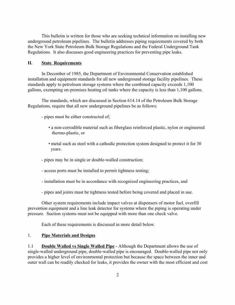
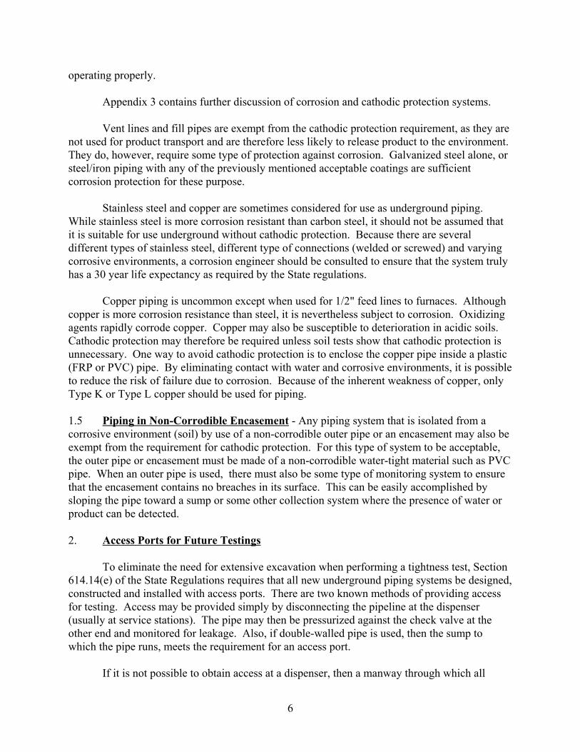
Figure 1 - Piping Layout
piping passes must be installed as required by the regulations.
3. Installation of Piping System
The Section 614.14(f) of the PBS regulations requires that all underground pipingsystems be installed in accordance with recognized engineering practices. The industrystandards for the installation of underground tanks including piping systems are PEI RP 100-97,Recommended Practices for Installation of Underground Liquid Storage Systems, and API 1615,Recommended Practices for Installation of Underground Petroleum Storage Systems.
The major points in underground piping system installation are as follows.
3.1 Trenching and Bedding - Whenever possible, product lines should be run in a singletrench between the tank area and pump island area. Vent lines between the tank area and thebuilding or other structure to which the aboveground vent lines are attached should also beinstalled in a single trench. (See Figure 1). Where more than one trench is needed, lines shouldnot cross each other or cross over underground tanks.
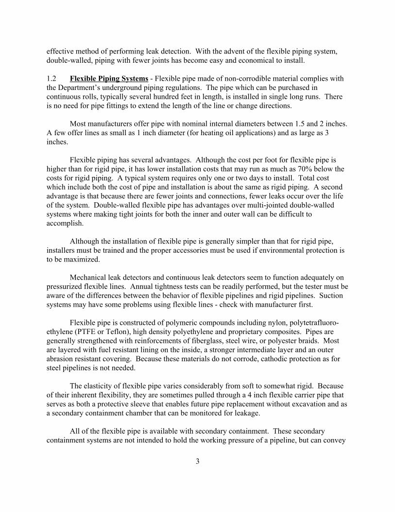
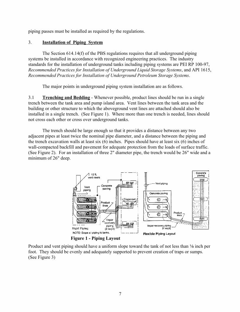
The trench should be large enough so that it provides a distance between any two adjacent pipes at least twice the nominal pipe diameter, and a distance between the piping andthe trench excavation walls at least six (6) inches. Pipes should have at least six (6) inches ofwall-compacted backfill and pavement for adequate protection from the loads of surface traffic. (See Figure 2). For an installation of three 2" diameter pipe, the trench would be 26" wide and aminimum of 26" deep.
Product and vent piping should have a uniform slope toward the tank of not less than c inch perfoot. They should be evenly and adequately supported to prevent creation of traps or sumps. (See Figure 3)
8
Figure 3 - Piping Dimensions
Figure 2 - Trench Dimensions
Steel piping may be backfilled with clean, inert, wellcompacted sand, pea gravel, or crushed stone, whileflexible piping and rigid FRP piping should only bebackfilled with sand or pea gravel (not crushed stone).Before covering the pipe, any rocks, debris, chocks, ice,snow, organic materials, or bracing used duringconstruction should be removed.
Before backfilling a non-metallic system, a metaltape or copper wire should be laid beside the pipingsystem so that the piping system could be relocated in thefuture using a metal detector.
3.2 Manufacturer’s Instructions - In addition to the industry standards cited above,installers should follow manufacturer’s instructions. Each product will have somewhat differentinstallation specifications.
Flexible piping systems require wide sweeping turns with an 18" to 36" minimum bendradius and may have some problems with suction system - check with the manufacturer first.
For FRP systems, good pipe joints are vital to a tight systems. Pipe joints must bestraight and must be fully seated. The joint adhesive used must conform to the manufacturer’srecommendations for underground petroleum service and must not be used at temperaturesbelow the recommended minimum.
For steel systems, cathodic protection system including coating, wrapping, and galvanicanodes or an impressed current system for metallic piping must be designed by a corrosionengineer or pursuant to standards set forth in PEI RP 100-97,
Installation of unions underground is not recommended. If unavoidable, the unions
9
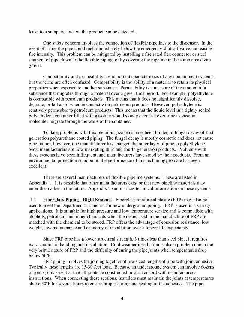
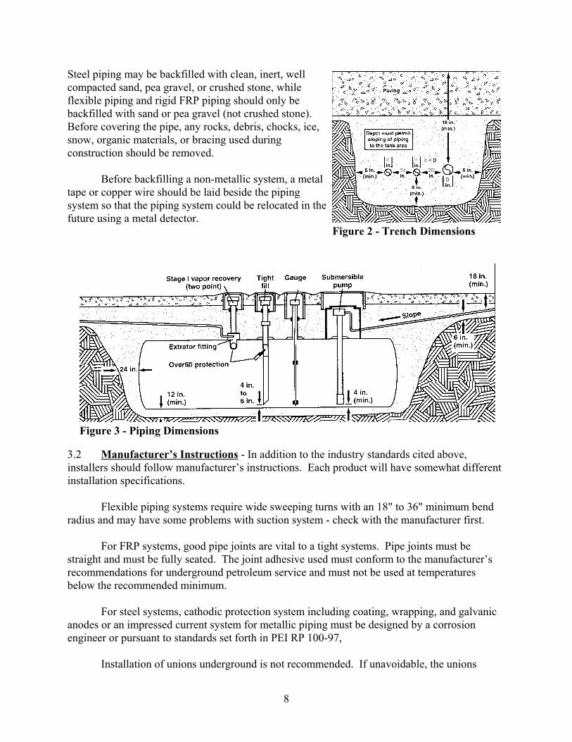
Figure 4 - Flexible Connector
should be at least schedule 80 or higher. Couplings furnished to protect metallic pipe threads arenot generally suitable for use underground. Dispensers, submerged pumps, check valves, orother metallic components, not intended to be protected by the cathodic protection systemprovided for the piping, should be electrically isolated. This would be done by providingdielectric bushings at the tank top and dielectric unions under the dispenser. Dielectric unionsshould be 600 X.H. psi or heavier.
3.3 Flexible Connectors - Frost heaving and subsidencecan damage underground pipes, especially when the pipe isconnected to a fixed object such as a pump dispenser. Flexibility must be provided for FRP and steel piping at thetank, under the dispenser, and where the piping changesdirection. This facilitates alignment of piping and equipment,also provides for differential movement and relieves stress. Flexible connectors should be used instead of swing joints orclosed elbows for direction changes (See figure 4).
4. Inspection and Testing of New Systems
4.1 System Inspection - Inspection is one of the most important steps to installing a trouble-free piping system. When the materials arrive on site, piping, including coatings, should beinspected for signs of damage. Inspection should continue during handling, installation, testingand backfilling to ensure that damage does not occur and that the system is installed pursuant toPEI RP 100-97.
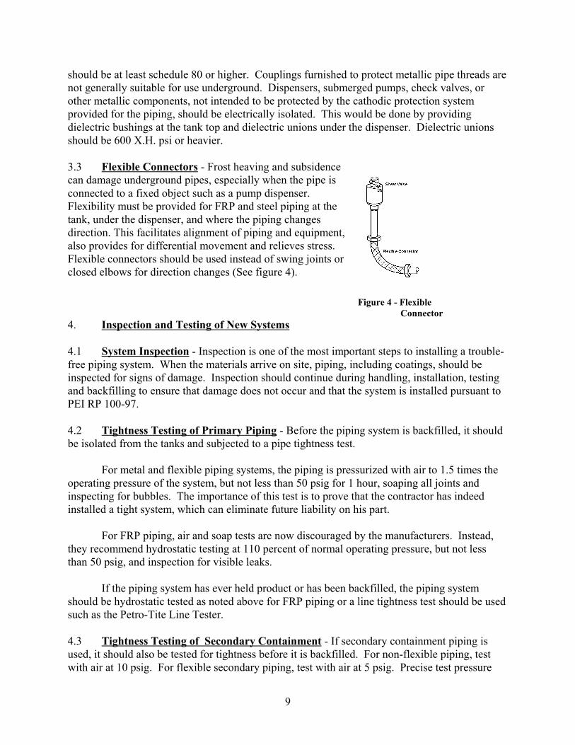
4.2 Tightness Testing of Primary Piping - Before the piping system is backfilled, it shouldbe isolated from the tanks and subjected to a pipe tightness test.
For metal and flexible piping systems, the piping is pressurized with air to 1.5 times theoperating pressure of the system, but not less than 50 psig for 1 hour, soaping all joints andinspecting for bubbles. The importance of this test is to prove that the contractor has indeedinstalled a tight system, which can eliminate future liability on his part.
For FRP piping, air and soap tests are now discouraged by the manufacturers. Instead,they recommend hydrostatic testing at 110 percent of normal operating pressure, but not lessthan 50 psig, and inspection for visible leaks.
If the piping system has ever held product or has been backfilled, the piping systemshould be hydrostatic tested as noted above for FRP piping or a line tightness test should be usedsuch as the Petro-Tite Line Tester.
4.3 Tightness Testing of Secondary Containment - If secondary containment piping isused, it should also be tested for tightness before it is backfilled. For non-flexible piping, testwith air at 10 psig. For flexible secondary piping, test with air at 5 psig. Precise test pressure
10
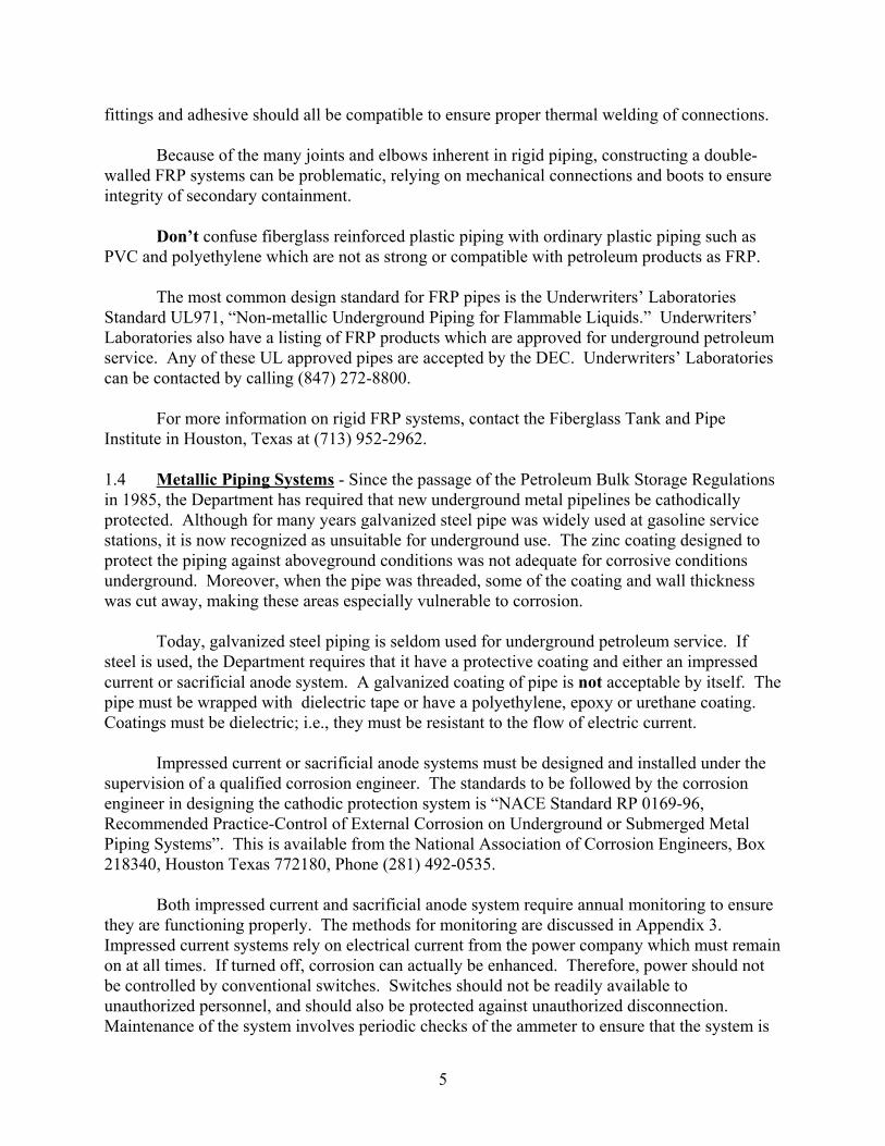
Figure 5 - Shear (Impact) Valve
and testing procedures for secondary piping are prescribed by each manufacturer and should bestrictly followed.
Impervious barriers, if used, should be inspected to determine whether any damage hasoccurred before being covered. Liner manufacturers provide instructions for proper testing oftheir products as well as instructions for making any repairs. Replace the liner or repair anydamage in accordance with the manufacturer’s instructions. This work should be performedonly by a liner manufacturer-trained personnel.
4.4 Testing of Corrosion Protection System - For steel piping with a cathodic protectionsystem (galvanic anodes or an impressed current), the cathodic protection system must be testedwithin three (3) to six (6) months after installation. The test for electrical continuity between thetank and associated piping must be performed. If dielectric bushings, flanges, or unions areinstalled, no continuity should exist between the tank and piping.
The owner/operator should keep a copy of all final test results and operating instruction.
5. Other System Requirements
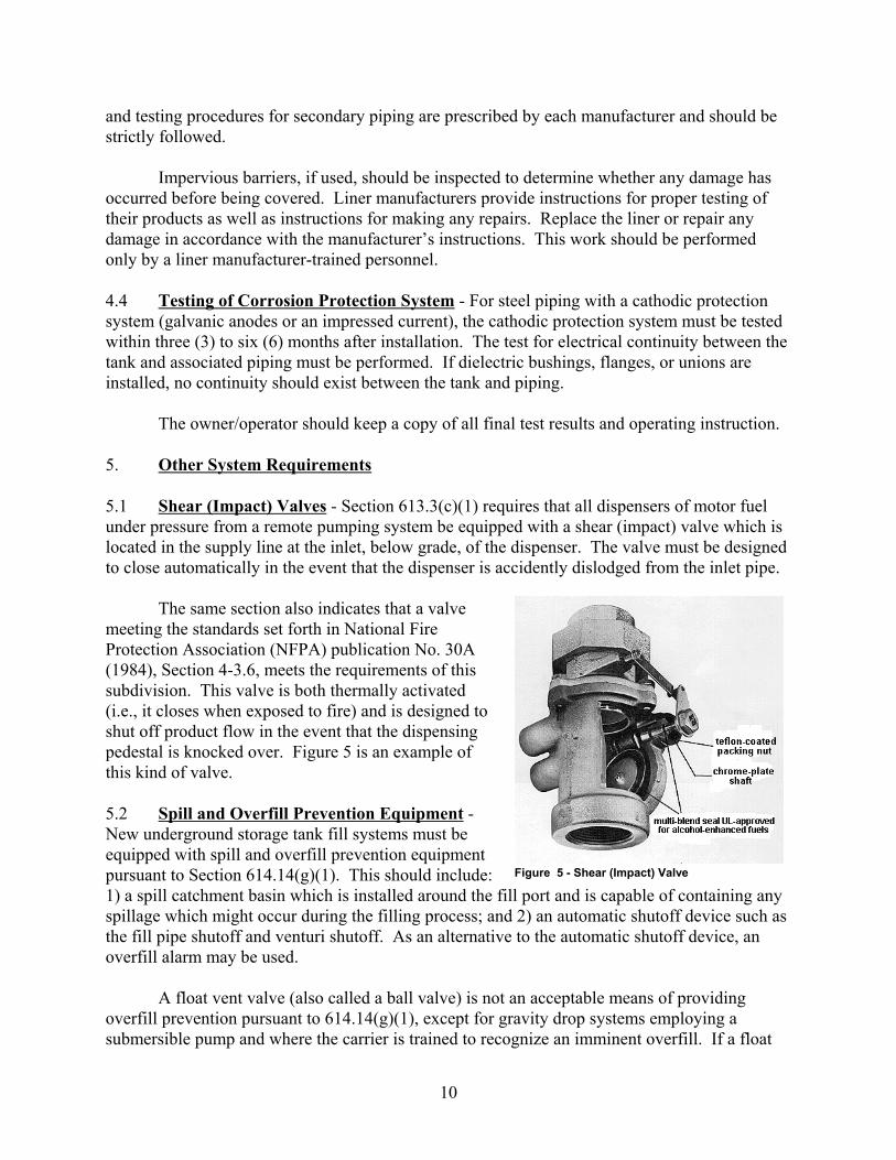
5.1 Shear (Impact) Valves - Section 613.3(c)(1) requires that all dispensers of motor fuelunder pressure from a remote pumping system be equipped with a shear (impact) valve which islocated in the supply line at the inlet, below grade, of the dispenser. The valve must be designedto close automatically in the event that the dispenser is accidently dislodged from the inlet pipe.
The same section also indicates that a valvemeeting the standards set forth in National FireProtection Association (NFPA) publication No. 30A(1984), Section 4-3.6, meets the requirements of thissubdivision. This valve is both thermally activated(i.e., it closes when exposed to fire) and is designed toshut off product flow in the event that the dispensingpedestal is knocked over. Figure 5 is an example ofthis kind of valve.
5.2 Spill and Overfill Prevention Equipment -New underground storage tank fill systems must beequipped with spill and overfill prevention equipmentpursuant to Section 614.14(g)(1). This should include:1) a spill catchment basin which is installed around the fill port and is capable of containing anyspillage which might occur during the filling process; and 2) an automatic shutoff device such asthe fill pipe shutoff and venturi shutoff. As an alternative to the automatic shutoff device, anoverfill alarm may be used.
A float vent valve (also called a ball valve) is not an acceptable means of providingoverfill prevention pursuant to 614.14(g)(1), except for gravity drop systems employing asubmersible pump and where the carrier is trained to recognize an imminent overfill. If a float
11
Figure 6 - Check Valve
vent valve is used, a permanent label warning against pump filling must be affixed at the fillport.
For a further discussion of overfill prevention equipment , see SPOTS Memo #6,“Overfill/Spill Prevention Equipment For Petroleum Storage Tanks.”
5.3 Pipe (Line) Leak Detectors - Petroleum is transported in pipes in one of two ways; bypressure, using a remote pump in or near the tank or by suction using a suction pump under thedispenser. If a leak occurs, a pressurized pipe will result in a larger spill than a pipe operatingunder suction.
Section 614.14(g) of the State Petroleum Bulk Storage Regulations requires that allpressurized piping systems built after December 1986, be equipped with a line leak detectorcapable of detecting pressure or product loss on the discharge side of a delivering pump.
Line leak detectors are operated by using; 1) a pressure-sensing-and-reacting mechanismto signal if there is a leak, or 2) a sensor to determine if there is a detected product and/or waterexisting in the space being measured. The latter devices are mostly used in interstitial spaces asthose in the double-wall tanks or double-wall pipes. Appendix 4 is an illustration of thepressure-sensing-and-reacting line leak detector.
Most importantly, an owner/operator should be prudent in choosing a system that hasbeen evaluated and accepted by a nationally recognized testing organization.
These detectors should be tested for proper operation at least annually or in accordancewith their manufacturer’s instructions.
Leak detectors are not required on suction systems because leaks are easily detected bythe decrease in product flow they cause, and also because air is pulled in through a leak ratherthan product being forced out of pipe.
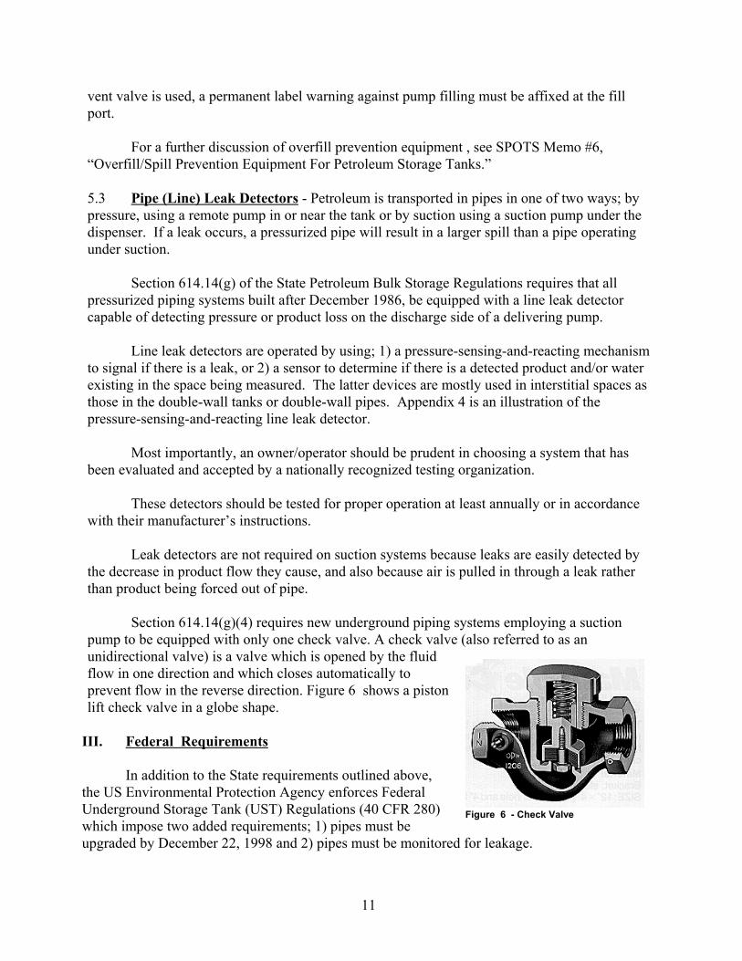
Section 614.14(g)(4) requires new underground piping systems employing a suctionpump to be equipped with only one check valve. A check valve (also referred to as anunidirectional valve) is a valve which is opened by the fluidflow in one direction and which closes automatically toprevent flow in the reverse direction. Figure 6 shows a pistonlift check valve in a globe shape.
III. Federal Requirements
In addition to the State requirements outlined above,the US Environmental Protection Agency enforces FederalUnderground Storage Tank (UST) Regulations (40 CFR 280)which impose two added requirements; 1) pipes must beupgraded by December 22, 1998 and 2) pipes must be monitored for leakage.
12
1. Upgrading
Upgrading means that new pipes meeting DEC’s requirements must be installed, orexisting pipes must be retrofitted with cathodic protection using an impressed current systemdesigned and installed under the supervision of a qualified corrosion specialist. Sacrificial anodesare inadequate for existing uncoated piping systems. A discussion of impressed current systemscan be found in the Appendix 1.
2. Leak Monitoring
Since December 1993, EPA has required leak detection for all federally regulatedunderground pipes. EPA requires that pressurized pipe meet the following;
- Pipes must have devices that automatically shut off or restrict flow, (such as the leak lineleak detector discussed under State regulations) or pipes must have an alarm that indicatesa leak with a sensibility as small as 3 gph at a line pressure of 10 psi.
- Pipes must be tightness tested annually, or one of the following monthly methods may be used: interstitial monitoring, vapor monitoring or groundwater monitoring or statisticalinventory reconciliation.
If suction piping is used, leak detection may or may not be required, depending on thesystem. No leak detection is needed if the system is sloped so that the pipe contents will drainback into the storage tank if the suction is released, and the system has only one check valve. This check valve must be located directly below the suction pump.
Suction piping that does not exactly match the characteristics noted above must have leakdetection which consist of either monthly monitoring (using one of the monthly methods notedabove for use on pressurized piping) or tightness testing every 3 years.
13
APPENDICES
APPENDIX 1
List of Manufacturers of Flexible Pipeline Systems
Name of Manufacturers Contact / Address Telephone Number
Advanced Polymer Technology, Inc. Bob Versaw (616) 759-911228605 County Road 6Elkhart, IN 46514
Ameron Fiberglass Pipe Systems Reid Van Cleave (713) 690-77775300 Hollister St. Suite 111Houston, TX 77040
Buffalo Environmental Products Corp. Dean Flessas (410) 553-01706720-F Ritchie Hwy #412Glen Burnie, MD 21061
Containment Technologies Corp. Kurt Steinbergs (612) 881-00721650 West 82nd St.Minneapolis, MN 55431
Environ Products, Inc. Chris Ursillo (610) 321-0200620 Pennsylvania Dr.Exton, PA 19341
Total Containment, Inc. Pierre Desjardins (610) 666-7777422 Business Center A130 North Dr.Oaks, PA 19464
Titeflex Industrial Americas Bill Watkins (413) 739-5631603 Hendee StreetSpringfield, MA 01139
Western Fiberglass, Inc. Richard Lewis (707) 523-2050 (a.k.a. Western FG) 1555 Copperhill Parkway
Santa Rosa, CA 95403
14
APP
EN
DIX
2.
Sum
mar
y of
Info
rmat
ion
Obt
aine
d fo
r Fl
exib
le P
ipel
ines
*
Com
pany
Nam
eN
umbe
r of
Inst
alla
tion*
*Pr
oduc
tN
ames
(s)
Mad
e Fr
omC
ompa
tible
Fuel
sA
vaila
ble
Size
s (ID
)U
LL
iste
dSt
anda
rdPe
rmea
bilit
yT
est
Pres
sure
to B
urst
Adv
ance
dPo
lym
erTe
chno
logy
100
Poly
-Tec
hN
ylon
12;
Nyl
on 6
yarn
; Pol
yeth
ylen
epi
ping
Fuel
C; E
than
ol;
Met
hano
l; G
asol
ine/
alco
hol b
lend
s
1.75
", 3
"N
oB
eing
test
ed u
nder
UL
971
Yes
900
psi
Am
eron
4D
ural
oy 3
000/
FLEp
oxy/
fiber
glas
sPe
trole
um p
rodu
cts;
100%
alc
ohol
s;al
coho
l/ ga
solin
em
ixtu
res
1.5"
Yes
UL
971
Yes
3,20
0 ps
i
Buf
falo
150
Buf
flex
Buf
flex
IITh
erm
opla
stic
tube
with
hig
h de
nsity
poly
ethy
lene
Petro
leum
; alc
ohol
and
alco
hol b
lend
s1"
, 1.5
",2"
No
AN
SI B
31.3
Yes
(but
not
to U
Lst
anda
rd p
roce
dure
)>5
00 p
si
Con
tain
men
tTe
chno
logi
es20
Flex
pipe
Poly
mer
spo
lyet
hyle
ne tu
bew
ith fi
tting
s
Gas
olin
e; a
lcoh
olN
oSw
edis
h N
atio
nal
Test
ing
Inst
itute
Yes
>5 ti
mes
ope
ratin
gpr
essu
re (n
ot te
sted
tode
stru
ctio
n)
Envi
ron
Prod
ucts
400
Geo
flex
Fibe
r-re
info
rced
ther
mop
last
icco
mpo
site
All
petro
leum
prod
ucts
; alc
ohol
s;bl
ends
1.5"
, 2"
Cur
rent
lyun
der t
estin
gU
L 97
1Y
es72
5 ps
i
Tota
lC
onta
inm
ent
3000
Envi
rofle
xEn
viro
flex
IIEn
gine
ered
ther
mo-
plas
tics
Petro
leum
pro
duct
s;M
TBE;
alc
ohol
s; a
llbl
ends
1.5"
, 2.5
"Y
es(P
etro
leum
; in
proc
ess f
oral
c.)
UL
971
Yes
>450
psi
Tota
l No.
3624
*
som
e in
form
atio
n ta
ken
from
“Pi
ping
Tec
hnol
ogy”
, The
Jour
nal o
f Pet
role
um M
arke
ting,
Apr
il, 1
993
**es
timat
es o
btai
ned
from
eac
h m
anuf
actu
rer
15
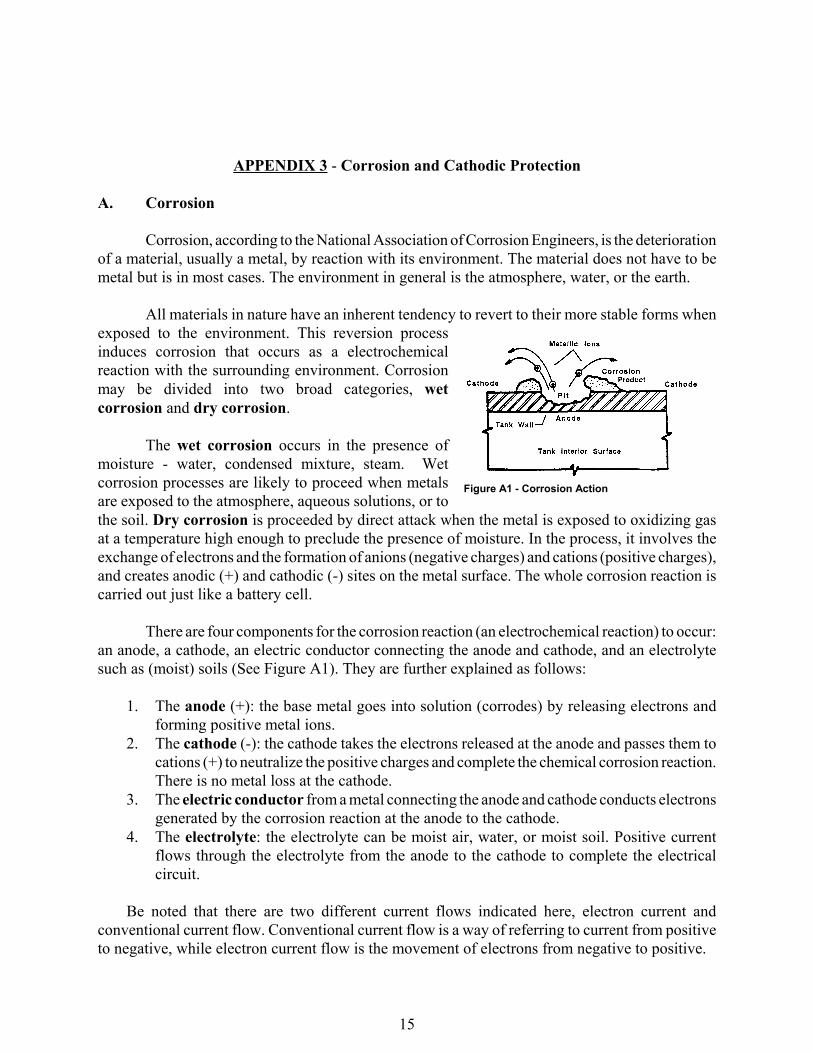
Figure A1 - Corrosion Action
APPENDIX 3 - Corrosion and Cathodic Protection
A. Corrosion
Corrosion, according to the National Association of Corrosion Engineers, is the deteriorationof a material, usually a metal, by reaction with its environment. The material does not have to bemetal but is in most cases. The environment in general is the atmosphere, water, or the earth.
All materials in nature have an inherent tendency to revert to their more stable forms whenexposed to the environment. This reversion processinduces corrosion that occurs as a electrochemicalreaction with the surrounding environment. Corrosionmay be divided into two broad categories, wetcorrosion and dry corrosion.
The wet corrosion occurs in the presence ofmoisture - water, condensed mixture, steam. Wetcorrosion processes are likely to proceed when metalsare exposed to the atmosphere, aqueous solutions, or tothe soil. Dry corrosion is proceeded by direct attack when the metal is exposed to oxidizing gasat a temperature high enough to preclude the presence of moisture. In the process, it involves theexchange of electrons and the formation of anions (negative charges) and cations (positive charges),and creates anodic (+) and cathodic (-) sites on the metal surface. The whole corrosion reaction iscarried out just like a battery cell.
There are four components for the corrosion reaction (an electrochemical reaction) to occur:an anode, a cathode, an electric conductor connecting the anode and cathode, and an electrolytesuch as (moist) soils (See Figure A1). They are further explained as follows:
1. The anode (+): the base metal goes into solution (corrodes) by releasing electrons andforming positive metal ions.
2. The cathode (-): the cathode takes the electrons released at the anode and passes them tocations (+) to neutralize the positive charges and complete the chemical corrosion reaction.There is no metal loss at the cathode.
3. The electric conductor from a metal connecting the anode and cathode conducts electronsgenerated by the corrosion reaction at the anode to the cathode.
4. The electrolyte: the electrolyte can be moist air, water, or moist soil. Positive currentflows through the electrolyte from the anode to the cathode to complete the electricalcircuit.
Be noted that there are two different current flows indicated here, electron current andconventional current flow. Conventional current flow is a way of referring to current from positiveto negative, while electron current flow is the movement of electrons from negative to positive.
16
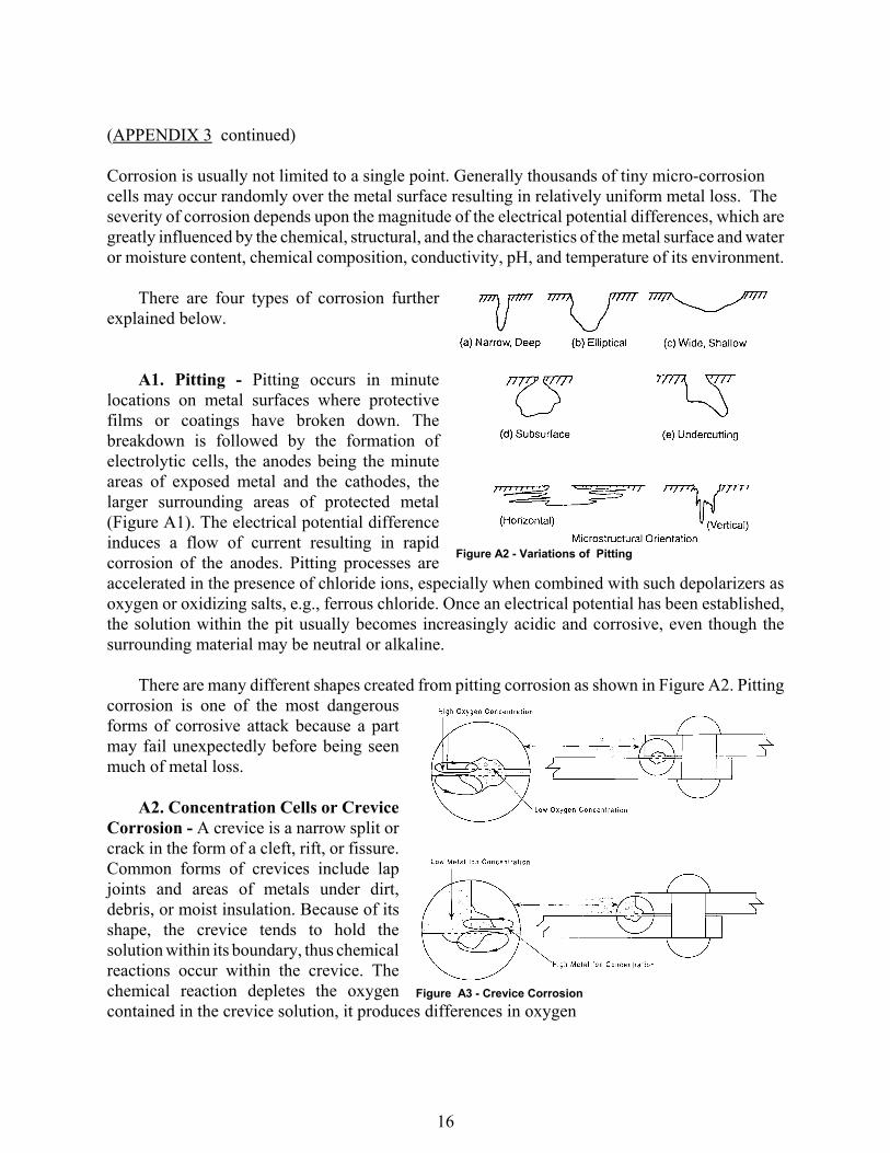
Figure A2 - Variations of Pitting
Figure A3 - Crevice Corrosion
(APPENDIX 3 continued)
Corrosion is usually not limited to a single point. Generally thousands of tiny micro-corrosion cells may occur randomly over the metal surface resulting in relatively uniform metal loss. The severity of corrosion depends upon the magnitude of the electrical potential differences, which aregreatly influenced by the chemical, structural, and the characteristics of the metal surface and wateror moisture content, chemical composition, conductivity, pH, and temperature of its environment.
There are four types of corrosion furtherexplained below.
A1. Pitting - Pitting occurs in minutelocations on metal surfaces where protectivefilms or coatings have broken down. Thebreakdown is followed by the formation ofelectrolytic cells, the anodes being the minuteareas of exposed metal and the cathodes, thelarger surrounding areas of protected metal(Figure A1). The electrical potential differenceinduces a flow of current resulting in rapidcorrosion of the anodes. Pitting processes areaccelerated in the presence of chloride ions, especially when combined with such depolarizers asoxygen or oxidizing salts, e.g., ferrous chloride. Once an electrical potential has been established,the solution within the pit usually becomes increasingly acidic and corrosive, even though thesurrounding material may be neutral or alkaline.
There are many different shapes created from pitting corrosion as shown in Figure A2. Pittingcorrosion is one of the most dangerousforms of corrosive attack because a partmay fail unexpectedly before being seenmuch of metal loss.
A2. Concentration Cells or CreviceCorrosion - A crevice is a narrow split orcrack in the form of a cleft, rift, or fissure.Common forms of crevices include lapjoints and areas of metals under dirt,debris, or moist insulation. Because of itsshape, the crevice tends to hold thesolution within its boundary, thus chemicalreactions occur within the crevice. Thechemical reaction depletes the oxygencontained in the crevice solution, it produces differences in oxygen
17
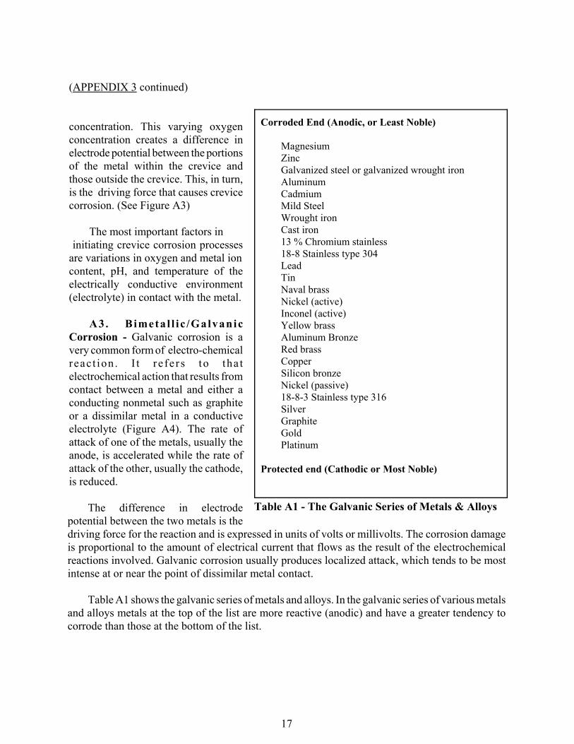
Corroded End (Anodic, or Least Noble)
MagnesiumZincGalvanized steel or galvanized wrought ironAluminumCadmiumMild SteelWrought ironCast iron13 % Chromium stainless18-8 Stainless type 304LeadTinNaval brassNickel (active)Inconel (active)Yellow brassAluminum BronzeRed brassCopperSilicon bronzeNickel (passive)18-8-3 Stainless type 316SilverGraphiteGoldPlatinum
Protected end (Cathodic or Most Noble)
Table A1 - The Galvanic Series of Metals & Alloys
(APPENDIX 3 continued)
concentration. This varying oxygenconcentration creates a difference inelectrode potential between the portionsof the metal within the crevice andthose outside the crevice. This, in turn,is the driving force that causes crevicecorrosion. (See Figure A3)
The most important factors in initiating crevice corrosion processesare variations in oxygen and metal ioncontent, pH, and temperature of theelectrically conductive environment(electrolyte) in contact with the metal.
A3. Bimeta l l i c /GalvanicCorrosion - Galvanic corrosion is avery common form of electro-chemicalreact ion . I t re fe rs to tha telectrochemical action that results fromcontact between a metal and either aconducting nonmetal such as graphiteor a dissimilar metal in a conductiveelectrolyte (Figure A4). The rate ofattack of one of the metals, usually theanode, is accelerated while the rate ofattack of the other, usually the cathode,is reduced.
The difference in electrodepotential between the two metals is thedriving force for the reaction and is expressed in units of volts or millivolts. The corrosion damageis proportional to the amount of electrical current that flows as the result of the electrochemicalreactions involved. Galvanic corrosion usually produces localized attack, which tends to be mostintense at or near the point of dissimilar metal contact.
Table A1 shows the galvanic series of metals and alloys. In the galvanic series of various metalsand alloys metals at the top of the list are more reactive (anodic) and have a greater tendency tocorrode than those at the bottom of the list.
18
Figure A4 - Bimetal Corrosion
Figure A5 - Stray Current Corrosion
(APPENDIX 3 continued)
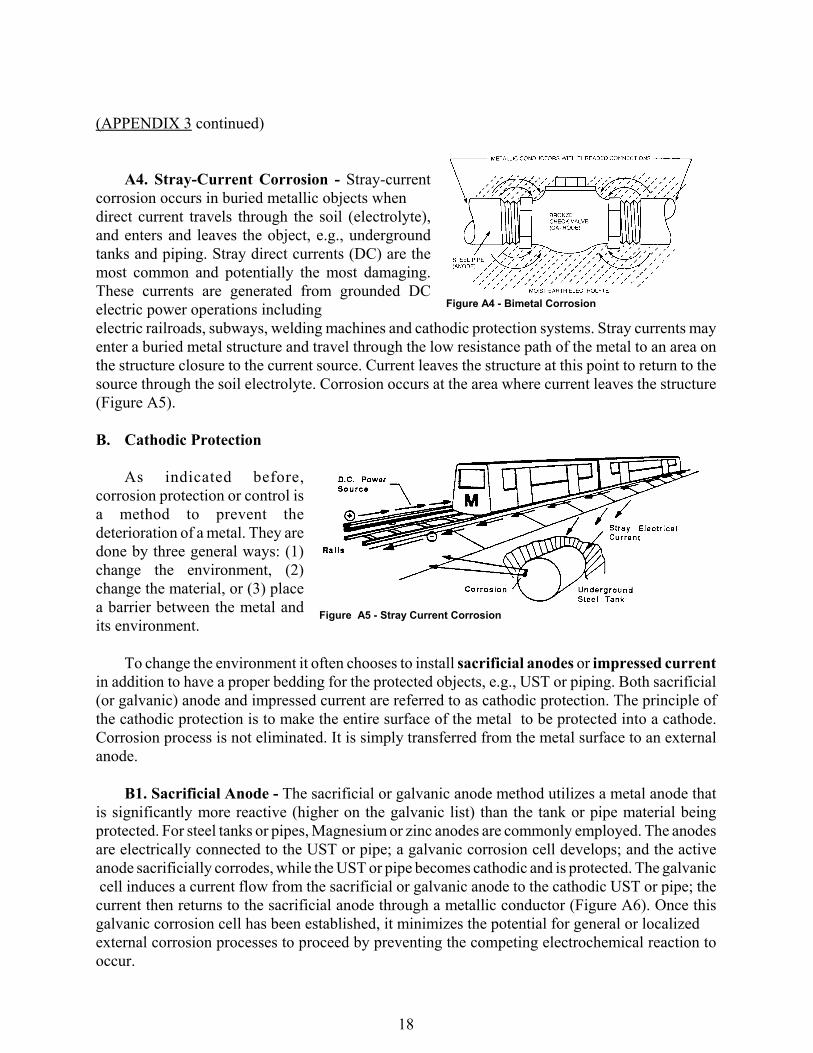
A4. Stray-Current Corrosion - Stray-currentcorrosion occurs in buried metallic objects whendirect current travels through the soil (electrolyte),and enters and leaves the object, e.g., undergroundtanks and piping. Stray direct currents (DC) are themost common and potentially the most damaging.These currents are generated from grounded DCelectric power operations including electric railroads, subways, welding machines and cathodic protection systems. Stray currents mayenter a buried metal structure and travel through the low resistance path of the metal to an area onthe structure closure to the current source. Current leaves the structure at this point to return to thesource through the soil electrolyte. Corrosion occurs at the area where current leaves the structure(Figure A5).
B. Cathodic Protection
As indicated before,corrosion protection or control isa method to prevent thedeterioration of a metal. They aredone by three general ways: (1)change the environment, (2)change the material, or (3) placea barrier between the metal andits environment.
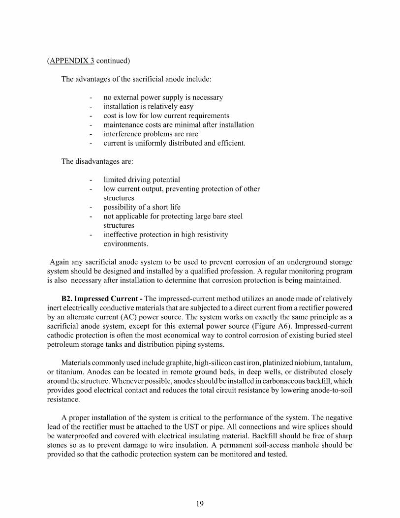
To change the environment it often chooses to install sacrificial anodes or impressed currentin addition to have a proper bedding for the protected objects, e.g., UST or piping. Both sacrificial(or galvanic) anode and impressed current are referred to as cathodic protection. The principle ofthe cathodic protection is to make the entire surface of the metal to be protected into a cathode.Corrosion process is not eliminated. It is simply transferred from the metal surface to an externalanode.
B1. Sacrificial Anode - The sacrificial or galvanic anode method utilizes a metal anode thatis significantly more reactive (higher on the galvanic list) than the tank or pipe material beingprotected. For steel tanks or pipes, Magnesium or zinc anodes are commonly employed. The anodesare electrically connected to the UST or pipe; a galvanic corrosion cell develops; and the activeanode sacrificially corrodes, while the UST or pipe becomes cathodic and is protected. The galvanic cell induces a current flow from the sacrificial or galvanic anode to the cathodic UST or pipe; thecurrent then returns to the sacrificial anode through a metallic conductor (Figure A6). Once thisgalvanic corrosion cell has been established, it minimizes the potential for general or localized external corrosion processes to proceed by preventing the competing electrochemical reaction tooccur.
19
(APPENDIX 3 continued)
The advantages of the sacrificial anode include:
- no external power supply is necessary- installation is relatively easy- cost is low for low current requirements- maintenance costs are minimal after installation- interference problems are rare- current is uniformly distributed and efficient.
The disadvantages are:
- limited driving potential- low current output, preventing protection of other
structures- possibility of a short life- not applicable for protecting large bare steel
structures- ineffective protection in high resistivity
environments.
Again any sacrificial anode system to be used to prevent corrosion of an underground storagesystem should be designed and installed by a qualified profession. A regular monitoring programis also necessary after installation to determine that corrosion protection is being maintained.
B2. Impressed Current - The impressed-current method utilizes an anode made of relativelyinert electrically conductive materials that are subjected to a direct current from a rectifier poweredby an alternate current (AC) power source. The system works on exactly the same principle as asacrificial anode system, except for this external power source (Figure A6). Impressed-currentcathodic protection is often the most economical way to control corrosion of existing buried steelpetroleum storage tanks and distribution piping systems.
Materials commonly used include graphite, high-silicon cast iron, platinized niobium, tantalum,or titanium. Anodes can be located in remote ground beds, in deep wells, or distributed closelyaround the structure. Whenever possible, anodes should be installed in carbonaceous backfill, whichprovides good electrical contact and reduces the total circuit resistance by lowering anode-to-soilresistance.
A proper installation of the system is critical to the performance of the system. The negativelead of the rectifier must be attached to the UST or pipe. All connections and wire splices shouldbe waterproofed and covered with electrical insulating material. Backfill should be free of sharpstones so as to prevent damage to wire insulation. A permanent soil-access manhole should beprovided so that the cathodic protection system can be monitored and tested.
20
Figure A6 - Sacrificial Anode/Impressed Current
(APPENDIX 3 continued)
The advantages of the impressed-current method are:
- large driving potential- high current output capable of protecting other underground steel structures with
a low operating cost- possibility of flexible current output- applicability to almost any soil resistivity- anode does not degrade.
The disadvantages are:
- may cause interference problems on foreign structures- possible to switch off current and eliminate protection- must be monitored and maintained on a regular schedule- more expensive- over-protection induced coating damage- monthly power bills
21
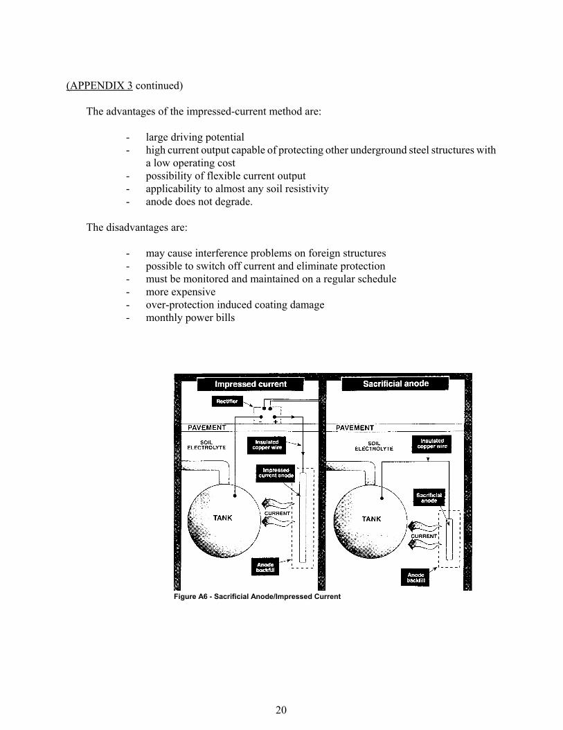
1.The Down position. Under normalconditions, the lines are filled withproduct.When the system pressure is lessthan 1 psi,the piston and poppet are in thedown position.At down position it allowsapproximately 1.5 to 3 gpm flow into thedelivery line through a bypass opening in thePLD valve poppet when the pumpstarts.Since the system is full,pressure buildsrapidly and the poppet moves to the leaksensing position assuming there is noleak.The pressure relief valve prevents anypressure build up under piston when in downposition by allowing relief of trappedproduct.
2.Leak Sensing Position.As the pressurebuilds to about 20 to 22 psi,the piston hasmoved the poppet to such a position as toalmost stop the flow into the piping throughthe poppet. In this position,all the flow mustthen travel around the metering pin whichlimits it to approxi. 3 gph.If a simultaneousloss from the system equals or exceeds thisamount,the line pressure will not buildbeyond this point and the valve will remain inthe leak sensing position with the main flowblocked.If there is an attempt to dispensewhile the valve in this position,the linepressure will drop,the piston will respond,and the poppet will return to Position 1 wherethe 1.5 to 3 gpm will flow to the dispensers.Leaks smaller than 3 gph will be indicated bythe PLD taking longer than 2
seconds to open completely. If there is noleakage in the system, the small flow aroundthe metering pin increases the line pressure to22 psi in about 2 seconds at which point thepiston will snap the poppet to Position3,allowing full flow.Any product relievedthrough pressure relief valve during downposition will be vented through vent tube totank.This allows piston to move freely withno back pressure to hamper its movement.3. Non-Leak Position.This position allowsfull flow.The poppet will remain in thisposition as long as the system pressureremains above 1 psi.At less than 1 psi,thepoppet will return to Position 1 and next timethe pump is activated,the PLD will perform aline test.
APPENDIX 4 - Red Jacket’s Piston Line Leak Detector