Embed Size (px)
Citation preview

Underground Residential Electric Service
FOR NEW DEVELOPMENTS
© SCANA Corporation 2018
Revised: February 2019

Table of Contents
Underground Residential Electric Service for New Developments
Section Page
Section 1: Purpose ..................................................................................................2
Section 2: Preliminary Conditions ...........................................................................3
Section 3: Developer’s Responsibilities...................................................................5
Section 4: Company Responsibilities ......................................................................11
Section 5: Design Guidelines ..................................................................................12
Definitions ...............................................................................................................14
Information ..............................................................................................................18
Construction Drawings ............................................................................................20
© SCANA Corporation 2018 1

Section 1: Purpose
101. This booklet is issued as a general guideline for owners and developers who desiresingle-phase underground service for residential subdivisions, apartmentcomplexes, condominiums and mobile home parks. The developer/owner shouldcontact the Company as soon as possible in the planning stage of the project toaddress electrical service issues such as voltage, service point, etc.
102. Requests by individuals for underground service to their residence will be handledin accordance with current company policies.
© SCANA Corporation 2018 2

Section 2: Preliminary Conditions The Company will consider furnishing underground, single-phase service for a developer who proposes the erection, as a unit, of a group of new single-family dwelling units or a group of new individually metered apartments or condominiums or a group of mobile homes in accordance with the following conditions: 201. Development must be on a single parcel of land suitable for underground
distribution. Developer will pay an aid to construction for special construction techniques, additional facilities required and/or additional installation costs for conditions such as but not limited to abnormal rock, open drainage, ditches, streams, unmanageable terrain, or bodies of water, flora or trees which must be avoided.
202. There must be a minimum of 24 dwelling units or lots in a contiguous arrangement.
Residential developments of less than 24 dwelling units, lots that are larger than 1 acre or lots that require special consideration will require an aid to construction.
203. Acceptable project development plans and construction schedules must be
provided and approved by appropriate governmental authorities. 204. The site shall have an established water, drainage and sewer system with a
minimum separation of eight feet between electric facilities and any parallel run of these lines. In addition, a minimum separation of 15 feet between electric facilities and drainage fields and septic tanks is required.
205. The Developer or customer shall pay to the Company the total estimated cost (as
determined by the Company) for that portion of all services in excess of 125 feet in length in the planned development.
206. The total estimated cost in providing underground service to the development,
including meters and services, must be no more than the estimated annual revenue, excluding fuel surcharge, times a multiplier as determined by SCE&G in effect at the time agreements are signed; otherwise, the Developer shall be required to pay the difference in advance.
207. The total estimated cost to provide street lighting, including fixtures, poles,
associated hardware, trenching and backfilling, must be no more than the estimated annual revenue, excluding fuel surcharge, times a multiplier as determined by SCE&G in effect at the time agreements are signed; otherwise, the
© SCANA Corporation 2018 3

Developer shall be required to pay the difference in advance. Street lighting will be installed in a regular pattern and in accordance with an orderly schedule as mutually agreed upon between the Developer, Municipalities, and SCE&G Co. The schedule may be adjusted based on progress with the development of the tract.
208. The Company will provide one service per lot. Any additional services (i.e. -
garages, workshops, apartments, detached structures) will be treated as non-residential and developer or owner will be required to purchase, install, own and maintain the service which will be run to a service point (typically transformer or pedestal) identified by the Company. The Company may offer to install the service to the additional structure at the customer’s expense.
209. Developer is required to take service at point specified by the Company. This
applies to residences, detached structures, apartment buildings, and mobile homes. All additional costs (initial and/or annual) will be paid by the developer for additional services provided at locations other than specified by the Company.
© SCANA Corporation 2018 4

Section 3: Developer’s Responsibilities
301. Furnish a plat (in electronic format, at no charge to the Company) showing detailedlayout including property and lot lines, street names, buildings, dedicatedeasements, sediment and erosion control measures, water, sewage, drainage andany other underground facilities (See paragraph 401). Provide informationconcerning expected housing size, restrictions and other information, which mayaffect energy requirements.
302. Provide suitable easements for electric service as determined by the Companyrepresentative including restrictions to prevent encroachments, which mayinterfere with the continued operation and maintenance of the underground electricfacilities.
303. Insert the following language (or equivalent) in the Restrictive Covenants coveringthis subdivision: "Developer has requested and Company has agreed to provideunderground electrical distribution facilities, with Developer having approved thesystem. Anyone desiring the relocation of any portion of the underground facilitiesshall request this service from the Company and pay the cost, providing suchrequested relocation is determined to be practicable. Any property owner havinga pad-mounted transformer on his property is required to maintain at least 12 feetof unencumbered space in front of the transformer doors for operation andmaintenance of the equipment. Further, property owners will grant Companyaccess for maintenance and/or replacement of transformers and undergroundpower lines. Company shall perform such maintenance in good workmanship likemanner and restore any disturbed property to as near original condition aspracticable."
304. Specify length of time anticipated for completion of project. Building constructionmust be done in a period of time deemed reasonable by the Company. ProjectDevelopment and building construction must follow a systematic pattern to allowconsistent underground distribution construction. The Company reserves the rightto collect construction costs up front to be reimbursed to the developer as homesare built and to be reimbursed for facilities installed which do not generateadequate revenue (i.e., construction of homes or buildings is not completed asoriginally planned).
305. Identify, install and maintain permanent property corners with lot numbersidentified on stakes in advance of any work to be performed by the Company.
© SCANA Corporation 2018 5

306. Provide information and arrange field spotting of water, sewer, drainage, and otherfacilities when requested by SCE&G. Company will assume no responsibility fordamage to facilities not marked. Underground electric facilities may be routed soas to avoid open drainage ditches, creeks and marsh areas.
307. Establish final grade before the start of any underground construction. Anychanges in grade that require changes or relocation of facilities shall be atDeveloper's expense.
308. Initiate stabilization measures as required both before and after installation ofunderground lines and include this activity in sequencing of construction activitiesin the Storm Water Pollution Prevention Plan. Developer will be responsible fortemporary stabilization, if necessary, once final grade is established and prior toCompany trenching activities. Do not initiate final stabilization on easement priorto Company installing underground lines. Any inlet protection will be responsibilityof the developer.
309. Provide a reasonably flat (8’ by 8’) area at final grade for pad-mountedtransformers locations.
310. Supplying and installing URD road crossings (as specified by SCE&Grepresentative, typically 2”-6” gray schedule 40 electrical conduit, refer to Drawing16.01-06) during subdivision road construction. Having conduit in place beforecompletion of the roads is very important. Developer has full responsibility forinstalling conduit road crossings at specified locations, to include boring andinstalling URD road crossings under existing roadways.
311. Notify the Company of any field changes in the original layout involving therelocation of its or other utilities' facilities. Developer shall be required to pay totalcost of relocation of the Company's facilities (including engineering cost) due tofield changes after print approval.
312. Furnish and install meter base, conduit and fittings, ground rod and ground wire inaccordance with Construction Drawing Section.
A. All work performed by the Developer shall be in compliance with the NationalElectric Code, all local codes and Company requirements.
B. The meter socket is to be installed on an exterior wall. In all cases, a Companyrepresentative must spot the service point in the field. If the meter socket is not
© SCANA Corporation 2018 6

installed at SCE&G spot location, socket must be relocated at customer's expense.
313. For Apartments and Condominiums
A. All meter sockets shall be clearly and permanently marked with enamel paint showing units served. The markings shall be on the inside of the meter socket and on the outside of the meter cover.
B. Requests for multiple services to one structure may be treated as non-
standard.
C. Typical service voltage for apartments and condominiums is 120/240V single phase. Requests for three phase service will be treated as commercial and must meet requirements in the SCE&G Underground Commercial Electric Service Manual and the SCE&G Electric Service and Meter Installations Manual.
D. Based on load information provided by the developer, SCE&G will estimate the
maximum demand for individual buildings and size transformers accordingly. Individual buildings with demand that exceeds what can be served by one (1) single-phase pad mount transformer on each end of the building will require three-phase service and must meet the requirements in the SCE&G Underground Commercial Electric Service Manual and the SCE&G Electric Service and Meter Installations Manual.
E. Developer shall execute a street light agreement with Company prior to
installation of any street or security lighting materials and/or equipment. All the lights will be totalized for single billing to the development owner.
314. Mobile Home Parks
A. Developers shall supply and install suitable metering facilities adjacent, but not attached to, mobile homes to include provisions for ground fault protection (where required by the National Electrical Code (NEC), Section 210.8(A)) in compliance with NEC, all local codes and Company requirements.
B. All metering facilities and pedestals furnished by the Developer shall be
approved by the Company prior to installation and their locations are to be spotted by a Company representative. The entire cost of any equipment
© SCANA Corporation 2018 7

change or relocation of services that was caused by not receiving prior approval shall be borne by the Developer or the party causing the condition, which necessitates the relocation.
C. All meter bases shall be clearly and permanently marked with enamel paint
showing the lot number served. Marking shall be on the inside of the meter socket and on the outside of the meter cover.
D. Developer shall furnish and install cable or conductors from metering facilities
to mobile homes.
E. Company and Developer will own and maintain their respective portion of the distribution system.
F. Agree to operate park continuously for a minimum term of five years or pay to
Company a termination charge not to exceed Company's total cost of installation, less depreciation, plus removal cost, less salvage.
G. Shall execute a street light agreement with Company prior to installation of any
street or security lighting materials and/or equipment. All the lights will be totalized for single billing to the park owner.
315. Install service (conductors and lugs) to commercial facilities (signs, leasing office,
etc.) at the Developer's expense from the mutually agreed upon metering point to the commercial facility.
316. Supply, install, operate and maintain phase converters for three phase loads
(where Developer has elected not to utilize single phase) in areas with only single phase available. In some cases, Developer can elect to pay a difference in cost and monthly operating fee for three-phase service in lieu of installing phase converter.
317. Execute a street lighting agreement with the Company if street lighting is desired
initially. If street lighting is desired at a later date, the Developer shall pay any additional cost of the installation. Street lighting inside municipal limits may need approval by the appropriate city official and comply with any applicable local ordinance.
318. Coordinate with the local governing body responsibility for monthly street lighting
charges. All lights not billed to a local governing body will be totalized for billing to
© SCANA Corporation 2018 8

the Developer or legally incorporated home owners association. 319. Perform necessary right-of-way clearing and clean up of debris from right-of-way
clearing operations for overhead and underground line construction. This would include limbs, trees and stumps.
320. Grading or site work performed on right-of-way (e.g. – landscaping, erosion
control, etc.) 321. Coordination of the approval of governmental agencies required for the
development (i.e.; buffer zones, wetlands, storm water permitting, zoning, etc.)
• Wetlands Provide official verification and confirmation of the wetlands and permits that have been issued, as stated in a letter from the U.S. Army Corps of Engineers (USACE). The letter must reference the detailed site plan drawing (same dated version) and include a file number. Stake or mark the wetlands boundaries prior to construction by SCE&G.
If unable to provide the above information, SCE&G will provide a Wetlands Determination Authorization Form for developer to sign giving SCE&G permission to have the impacted property surveyed for jurisdictional wetlands, which could include the USACE entering the property. Any costs associated with survey and resulting delineation required will be at developer’s expense.
• Storm Water
Obtain coverage under the NPDES General Permit for Storm Water Discharges from Construction Activities for all easements and areas of electric line construction and provide official verification of this coverage. Provide site maps showing the locations of all sediment and erosion control measures planned for electric line construction and include these areas in the Storm Water Pollution Prevention Plan.
Developer will be responsible for installation, maintenance, and inspection of all sediment and erosion control measures around electric lines. Notice of Termination will not be submitted by Developer prior to Company completing all electric line installation.
322. The developer will be fully responsible for compliance with any tree or buffer
ordinances affecting SCE&G easements. Any funding or tree replacement will be
© SCANA Corporation 2018 9

the responsibility of the developer. Buffer requirements are in addition to and separate from SCE&G easements. The developer should make himself fully aware of all appropriate ordinances that can affect SCE&G's right of way and should take this into account when assigning the easement.
323. The developer shall be fully responsible, as required by local ordinances, to
establish and maintain tree barricades around all trees that are required to be preserved. Any required barricades shall be in place prior to SCE&G beginning design or installation of underground facilities. The standard method of construction will be by an open-trench (trencher or back hoe). Any encroachments in barricaded areas will require directional bores to protect trees and shall be considered as non-standard service to the developer and at the developer’s expense. The developer shall be solely responsible and liable for any tree damage incurred during the installation of underground electric facilities, caused by the developer’s failure to properly barricade any significant trees, as prescribed by local ordinances.
© SCANA Corporation 2018 10

Section 4: Company Responsibilities
401. Prepare electrical distribution layout and lighting layout for Developer's writtenapproval prior to construction, after which changes requested by the Developerthat result in additional costs to the Company will be at the Developer's expense.Written approval may be defined as a signed copy of the distribution layoutprepared by the Company.
402. Perform necessary trenching and backfilling to install facilities. Developer isresponsible for all stabilization requirements, sediment and erosion controlmeasures, and clean up of debris from right-of-way clearing operations. Companywill utilize proper installation techniques, but is not responsible for damage tolandscape, bodies of water, trees or flora during installation of facilities.
403. Furnish, install, connect, and maintain all required primary distribution cables, pad-mounted transformers, pads, secondary conductors and services up to 125 feet.
© SCANA Corporation 2018 11

Section 5: Design Guidelines 501. The determination for the need of conduit for U.G. primary, secondary and street
light conductor or cables shall rest solely with the Company. 502. Only single-phase 120/240V, three wire service is available to residences. 503. All apartments and condominiums must be individually metered. 504. Environmentally sensitive areas must be shown on proposed layouts. (Wetlands,
bodies of water, cemeteries, historical sites, etc.) 505. Lots adjacent to overhead lines may be served from pole-mounted transformers
with underground services. 506. SCE&G will select type of construction and location of main feeders. Main feeders
will be overhead. Cable dip poles will be located on Developer's property. If the Developer desires underground main feeders, these may be provided if site conditions are acceptable to the Company and the Developer agrees to incur any additional costs that may apply.
507. Pad-mounted transformers will be located as to allow access for maintenance or
replacements. Clearance shall be 12 feet from equipment. 508. If street lighting and/or area lighting layouts are required, they shall be designed
concurrent with project layout and installation coordinated with other trenching. Such lighting can be installed only upon execution of an appropriate lighting contract.
509. Temporary service may be furnished from overhead facilities or from pad-mounted
transformers. Reasonable time must be allowed for construction of needed facilities. Temporary facilities will be installed and removed at the Developer's expense.
510. Piles of dirt, trees and brush, construction materials residue and equipment on or
near the planned facilities shall have been cleared away by the Developer prior to construction.
511. Underground service routes will run as straight as possible from Company
secondary facilities to customer's house and must be free of obstacles such as
© SCANA Corporation 2018 12

patios, driveways, walkways, etc. Conduit furnished by the Developer shall extend from the meter to a point beyond any surfaced areas adjacent to the building wall.
© SCANA Corporation 2018 13

Definitions 1) Application for Service: a mail, phone or personal request by the customer to the
Company stating a desire for electric service to be furnished at a certain location. 2) Building: a structure which stands alone or which is cut off from adjoining
structures by firewalls, as defined by the pertinent building codes, with all openings therein protected by approved fire doors.
3) Class of Service: the characteristics of electric service described in terms of
voltage, phase, frequency and number of wires. 4) Code: the National Electrical Code (NEC) and the National Electric Safety Code or
other electrical codes or regulations in effect in the area served. 5) Company: South Carolina Electric & Gas Company (SCE&G). 6) Cost or Expense: includes all labor, material and other applicable charges, plus
overheads. 7) Customer: either a present or a prospective user of the Company's electric service. 8) Developer: the party entering into the agreement with the Company. 9) Customer’s Installation: all wiring, conduit, service disconnecting devices,
appliances, lighting, and other equipment installed and owned by the customer on his premises for his use.
10) Customer Will Provide: or "will install" or "will have installed" or "will furnish"
and similar references: the Company expects the customer to provide and install the equipment in question. It is assumed that the customer will delegate this obligation to his bona fide agents. Actual electrical work and the furnishing of required materials are usually delegated to an electrician or an electrical contractor.
11) Distribution Lines: company lines located in or along streets, alleys, highways, rear
lot lines or elsewhere, and by easements, when used or intended for use for general distribution of electric service to customers.
12) Electrical Installation: the total electrical wiring and equipment installed on the
customer's premises.
© SCANA Corporation 2018 14

13) Fraudulent Use: obtaining electric and/or gas service by unlawful means. 14) Ground: a conducting connection between an electric circuit or equipment and earth,
or some conducting body that serves in place of the earth 15) Instrument Transformer: transformers used for reducing the current or voltage to
quantities suitable for metering. There are indoor and outdoor types. Indoor types must be installed in cabinets whether installed indoors or outdoors. Outdoor types are usually installed without cabinets but may sometimes be put in cabinets.
16) Instrument Transformer Cabinet: a sealable indoor metal box for housing
instrument transformers. 17) Line: a system of poles, wires and fixtures, or the equivalent ducts, conduits, cables,
etc. used for the distribution of electricity. It may be located in a street, highway, alley, or on a private right-of-way.
18) Line Extension: any addition to the Company's existing distribution lines and
facilities, which must be made to render electric service to a customer. 19) Manufactured Home: formally known as a mobile home which has been specifically
designed to meet HUD provisions. For information pertaining to electrical service attached to the manufactured home, see section 217 of the SCE&G Electric Service and Meter Installations Manual.
20) Meter: a device for measuring the electric power and energy supplied to a customer. 21) Meter Enclosure: a wood or metal cabinet, or metal socket, installed indoors or
outdoors, in which the Company's metering equipment is located. 22) Meter Socket: a meter socket is the base portion of a socket type meter. There are
numerous kinds of meter sockets such as light duty, heavy duty, multi-terminal, etc. all with various numbers and sizes of conduit openings. Each particular socket has a preferred application although some are interchangeable.
23) Meter Tampering: any attempt to alter the registration of use on an electric or gas
meter.
© SCANA Corporation 2018 15

24) Modular Home: any building including the necessary electrical, plumbing, heating,ventilating and other service systems manufactured off site and transported to thepoint of use for installation or erection with or without other specified components, asa finished building and not designed for ready removal to another site. This mustqualify under the S.C. Modular Building Construction Act, Regulation #19-460.15. Anyhome considered a modular home will have a certification label. This label verifies itto be a modular home and must be shown to the service representative before anyelectrical connection is made. See the SCE&G Electric Service and MeterInstallations Manual for additional details.
25) Overhead Distribution Areas: those areas in which the customer's premises abut oncompany overhead distribution facilities.
26) Rate Schedule Classification: the classification of the customer’s electric service forrate application as determined by the class of service, the amount of electric powersupplied and the purpose for which the electric service is to be used.
27) Service: the conductors and equipment for delivering energy from the Company's lineto the wiring system of the premises served.
a) Service drop: that portion of the overhead conductors between the Company’sdistribution facilities and the point of attachment at customer’s structure.
b) Service lateral: a system of underground conductors and equipment for deliveringelectricity from the Company’s distribution system to the wiring system of a buildingor premises.
c) Service entrance: the part of the wiring from the point of attachment or terminationof the service drop or service lateral to and including the service equipment on thecustomer’s premises.
d) Service equipment: the necessary disconnecting and protective equipment,usually consisting of a circuit breaker or a switch and fuses and their accessories,owned by the customer, located near the point where the service entranceconductors enter a building and intended to constitute the main control and meansof cutoff for the supply to that building.
e) Service connection: one service drop or a service lateral and its associatedservice entrance.
© SCANA Corporation 2018 16

f) Service entrance conductors: the supply conductors that extend from the point of attachment or termination of the service drop or service lateral to the service equipment on the premises being served.
g) Service entrance equipment: the service entrance conductors, raceway and
fittings or service entrance cable and fittings which are installed on the customer’s premises to connect the electric service to the wiring inside the building.
h) Service Raceway: the conduit containing the service entrance conductors.
28) Shall: mandatory in nature. 29) Temporary or seasonal service: will be furnished under the appropriate General
Service Rate Schedule to any Customer. Temporary service shall include all construction services and other services having a life expectancy of one year or less. Payment is required in advance for the full cost of erecting and removing all lines, transformers, and other service facilities necessary for the supply of such service.
30) Wetlands: those areas that are inundated or saturated by surface or ground water at
a frequency and duration sufficient to support, and that under normal circumstances do support, a prevalence of vegetation typically adapted for life in saturated soil condition. Wetlands generally include swamps, marshes, bogs and similar areas
© SCANA Corporation 2018 17

PROJECT NAME: ____________________________________________ DATE: _______________
Location: _________________________County:__________________Municipality:_______________
Developer/Contact: Engineering Firm: Name of Company: __________________________ Name of Company: _________________________ Name of contact person: _______________________ Name of contact person: ______________________ Address: ___________________________________ Address: ___________________________________ ____________________________________________
____________________________________________ Phone #’s: __________________________________ Phone ’s:___________________________________ Email: _____________________________________ Email:_____________________________________
Do site drawings have State, County or City approval? Yes or No, Anticipated Approval Date: ____________ Project Start Date: ____________________________ OCRM Site Inspection/Approval Date: _____________ Completion Date: ____________________________ Phases of Development: _________________________ TMS# _____________________________________
Type of Development:
Single-Family Homes Mobile Homes Duplexes Townhouses Condos Apartments For Multi-Family, what are the firewall ratings? ______ hours Size of Lots: ______ Number of Lots: ______ Number of Dwelling Units: _____ Avg. Unit Sq. Footage: ______
Main Panel Size: 100 Amps 150 Amps 200 Amps 400 Amps Other: _______ Amps
HVAC Capacity: 1-tons 2-tons 3-tons 4-tons Other: ______ tons
Pump Station Required: Yes or No
Single-Phase or Non-Standard Three-Phase Power Horsepower Rating: ________________ Voltage: 120/240 120/208 277/480
Street Lights required: Yes or No
Type: HPS Size: 150 watt 400 watt Number of Lights: ______ Style: Traditional Classic Round Octagonal Other: __________________ Type of Billing: Developer HOA Municipal Other: __________________________________________
Utilizing natural gas? Yes or No If yes: Heat Water Heater Other: _________________________
I HEREBY CERTIFY THAT THE INFORMATION PRESENTED HERE IS ACCURATE.
AUTHORIZED SIGNATURE: ______________________________________ DATE: ____________________
TITLE: ________________________________________________________ PHONE: ____________________
Information for Residential Service
© SCANA Corporation 2018 18

Developer Responsibility Checklist
Please initial each line and sign at the bottom acknowledging acceptance of these responsibilities:
______ Comply with all current SCE&G policies, including, but not limited to, the following (Copies of policies are on file with the South Carolina Public Service Commission and are available from SCE&G upon request):
______ General Terms and Conditions ______ Underground Residential Electric Service policy ______ Underground Commercial Electric Service policy ______ Electrical Service and Meter Installation policy
______ Comply with all federal, state and local regulatory restrictions and ordinances, including, but not limited to, those that pertain to tree ordinances, protected trees, buffer zones, building codes and electrical codes
______ Provide official verification and confirmation of the wetlands and permits that have been issued as stated in a letter from the U.S. Army Corps of Engineers or sign the Wetlands Determination Authorization form provided by SCE&G.
______ Pay any required Contribution In Aid of Construction fees
______ Grant suitable easement for the installation of SCE&G’s electric and/or gas facilities that will allow the installation of utility facilities by standard & conventional construction methods
______ Approve SCE&G’s proposed electrical design and communicate the plan and its requirements to all others involved in the project.
______ Provide and install suitable conduits for road crossings as specified by SCE&G representative
______ Install permanent property pins and establish final grade prior to the installation of electrical facilities
______ Provide immediate written notification to SCE&G of any changes to the original development layout
______ Notify contractors, sub-contractors and future owners of their responsibility to comply with current SCE&G Co. policies.
______ Insert appropriate SCE&G language in the Restrictive Covenants for the development concerning the accessibility for operations, meter reading and maintenance. Also, the requirements for unencumbered utility easements and proper clearances from SCE&G equipment.
SIGNATURE: ____________________________________________ DATE: _____________________
TITLE: __________________________________________________ PHONE: ____________________
© SCANA Corporation 2018 19

Drawing Table of Contents
Drawing Title
06.01-01 .................... Secondary and Service Construction 06.01-02 .................... Service Details 06.03-02A .................. Temporary Overhead Service Notes 06.03-02B .................. Temporary Overhead Service Pole 06.04-01A .................. Mobile Home Underground Service Notes 06.04-01B .................. Mobile Home Underground Service Pedestal 06.04-02A .................. Temporary Underground Service Notes 06.04-02B .................. Temporary Underground Service Pole / Pedestal 16.01-05 .................... Non-Joint Use Trenching Detail 16.01-06 .................... Road Crossing Detail 19.01-01 .................... Meter Sockets 19.01-03 .................... Meter Clearance Requirements 19.01-05 .................... Modular (Ganged) Meter Assembly 19.02-01 .................... Single-Phase 120V 2W Meter 19.02-02A .................. Single-Phase 120/240V 3W Meter (200 Amps) 19.02-02B .................. Single-Phase 120/240V 3W Meter (201 - 600 Amps)
© SCANA Corporation 2018 20

SECONDARY AND SERVICE
CONSTRUCTION
NOTES:
1. THE NEUTRAL SHALL BE COMMON TO BOTH PRIMARY AND SECONDARY CIRCUITS
ON WYE SYSTEMS AND THE NEUTRAL SHALL BE MULTI-GROUNDED (SEE SECTION 8
FOR ADDITIONAL INFORMATION).
2. THE NEUTRAL CONDUCTOR SHALL ALWAYS BE IN THE TOP POSITION ON ALL OPEN
WIRE SECONDARY CIRCUITS.
3. SIZING OF SECONDARY AND SERVICE CONDUCTORS WILL DEPEND ON THE AMOUNT
OF LOAD, THE TYPE OF LOAD (SUCH AS MOTORS, ETC.) AND THE VOLTAGE DROP.
THE REQUIRED SIZE SHALL BE SPECIFIED BY THE DESIGNER AND IDENTIFIED ON
ALL WORK ORDERS.
4. WHEN USED WITH A 477 AAC (SAC) NEUTRAL, THE PULLEY BRACKET WILL NOT
ACCOMMODATE SERVICE PAYOFFS. AS SUCH, A SECOND PULLEY BRACKET SHALL
BE INSTALLED UNDERNEATH THE NEUTRAL PULLEY BRACKET.
5. STREETLIGHT CIRCUITS ARE CONSIDERED AS SECONDARY.
6. SEE DRAWING 01.03-06 FOR CLEARANCE FROM SWIMMING POOLS.
7. SEE DRAWING 03.01-03 FOR OVERHEAD SECONDARY/SERVICE CONDUCTOR
AMPACITIES.
8. SEE DRAWING 14.02-01 FOR UNDERGROUND SECONDARY/SERVICE CONDUCTOR
AMPACITIES.
9. SEE DRAWINGS 15.01-04, 15.01-05A AND 15.01-05B FOR PAD MOUNT TRANSFORMER
AND CABLE IDENTIFICATION METHODS.
10.SEE DRAWING 06.01-02 FOR SERVICE DETAILS.
11.SEE THE SCE&G CONTRIBUTIONS IN AID OF CONSTRUCTION (CIAC) MANUAL FOR
ADDITIONAL DETAILS.
12.SEE SECTION 19 FOR METER SOCKET AND METERING DETAILS.
13.SEE THE TABLE BELOW FOR MAXIMUM UNGUYED MULTIPLEX SPAN LENGTH.
JAL
07-13-17
1
06.01-01
DISTRIBUTION CONSTRUCTION STANDARD
SOUTH CAROLINA ELECTRIC & GAS CO.
EFFECTIVE
DATE:
08-07-17
LIMIT FOR ALUMINUM MULTIPLEX
WIRES NOT REQUIRING GUYING
WIRE SIZE SPAN LENGTH
#4 DUPLEX 150'
#2 TRIPLEX 150'
1/0 TRIPLEX 125'
4/0 TRIPLEX 75'
1/0 QUADRUPLEX 100'
4/0 QUADRUPLEX 60'
500 QUADRUPLEX 50'
RE
V. 1 (07/13/17) - U
PD
AT
ED
D
RA
WIN
G N
UM
BE
RS
IN
N
OT
ES
8 &
9

SERVICE DETAILS
OVERHEAD SERVICES
THE POINT OF ATTACHMENT AT THE HOUSE, BUILDING OR OTHER APPROVED POINT OF
ATTACHMENT SHALL PROVIDE SUFFICIENT GROUND CLEARANCE AND BE OF SUFFICIENT
STRENGTH TO SUPPORT THE MAXIMUM EXPECTED LOAD OF THE SERVICE CONDUCTORS. ALL
SECONDARIES AND SERVICES SHALL MEET MINIMUM CLEARANCE REQUIREMENTS OVER ROOF,
SIDEWALK AND/OR STREET (SEE DRAWINGS 01.02-01, 01.03-01A AND 01.03-01B).
WIRE HOLDERS SHALL BE FURNISHED BY SCE&G AND INSTALLED BY THE CUSTOMER. SEE
DRAWING 06.01-07 FOR SERVICE ATTACHMENT DEVICES. SCREW-TYPE WIRE HOLDERS (HOUSE
KNOBS) OR OTHER ATTACHMENTS (TOGGLE BOLT OR LAG BOLT) SHALL BE SECURELY ANCHORED
INTO A STRUCTURAL MEMBER SUCH AS A STUD OR RAFTER OF WOOD FRAME BUILDINGS. POINTS
OF ATTACHMENT INSTALLED IN BRICK OR BLOCK STRUCTURES SHALL EMPLOY THE USE OF
LEAD-SHIELDS OR TOGGLE BOLTS. THESE DEVICES SHALL NOT BE INSTALLED IN MORTAR JOINTS;
RATHER THEY SHALL BE INSTALLED INTO OR THROUGH THE BRICK OR BLOCK ITSELF.
UNDERGROUND AND HYBRID SERVICES
1. FOR SERVICE IN CONDUIT, THE CONDUIT SHALL BE INSTALLED 30 INCHES BELOW GRADE WITH A
MINIMUM OF 36 INCH RADIUS SWEEPS. IF NECESSARY, CUSTOMER MUST MODIFY STRUCTURE
FOOTING TO ALLOW 36 INCH RADIUS SWEEP.
2. NO MORE THAN THREE (3) 90 DEGREE BENDS ARE PERMITTED IN A SERVICE WITHOUT
APPROVAL.
3. ALL CONDUIT SHALL BE ELECTRICAL GRADE SCHEDULE 40 PVC (GRAY).
4. 2 INCH CONDUIT IS REQUIRED FOR 200 AMP METERS.
5. 3 INCH CONDUIT IS REQUIRED FOR 201 - 600 AMP METERS.
6. SERVICE ROUTE MUST NOT BE IMPEDED BY DRIVEWAY, SIDEWALK OR OTHER OBSTRUCTION.
7. WEATHERHEAD IS REQUIRED IF SERVICE WIRE IS OWNED BY CUSTOMER.
MARKING OF PHASE ROTATION
ALL NEW THREE PHASE SERVICES SHALL BE MARKED TO IDENTIFY THE PHASE ROTATION. THIS
SHALL BE ACCOMPLISHED BY USING A PHASE ROTATION METER (STOCK CODE 071.1200.0055) AND
EITHER THE CLOCKWISE STICKER OR COUNTERCLOCKWISE STICKER SHOWN BELOW.
THE APPROPRIATE STICKER SHALL BE PLACED INSIDE THE METER BASE OR PAD MOUNTED
TRANSFORMER. FOR OVERHEAD CT SERVICES, THE ROTATION SHALL BE CHECKED AT THE CT'S ON
THE POLE AS FOLLOWS: TOP TO BOTTOM (RED, WHITE, BLUE), WITH THE HIGH LEG (IF PRESENT) IN
THE BOTTOM CT. VERIFY THE ROTATION IN THE CT METER BASE AS FOLLOWS: LEFT TO RIGHT (RED
TO RED, WHITE TO BLUE AND BLUE TO BLACK). ONCE VERIFIED, PLACE THE APPROPRIATE
ROTATION STICKER INSIDE THE CT METER BASE.
DURING STORM TROUBLE SERVICE RESTORATION, REMOVE THE CUSTOMER'S METER AND USE A
PHASE ROTATION METER TO ENSURE THE RECONNECTION WILL PROVIDE THE PROPER PHASE
ROTATION FOR THAT CUSTOMER AS INDICATED BY THE STICKER. IN ADDITION, IF THE SERVICE IS
DELTA, USE A VOLTMETER AT THE METER SOCKET TO ENSURE PROPER RECONNECTION OF THE
HIGH LEG/POWER LEG CONDUCTOR.
JAL
01-04-19
1
06.01-02
DISTRIBUTION CONSTRUCTION STANDARD
SOUTH CAROLINA ELECTRIC & GAS CO.
EFFECTIVE
DATE:
02-15-19
Red White Blue
Phase Rotation
Date:____________
A
B
C
Red White Blue
Phase Rotation
Date:____________
A
B
C
CLOCKWISE ROTATION
STOCK CODE: 080.7960.0120
COUNTERCLOCKWISE ROTATION
STOCK CODE: 080.7960.0122
RE
V. 1 (01/04/19) - U
PD
AT
ED
N
OT
ES
4 &
5 O
F U
ND
ER
GR
OU
ND
A
ND
H
YB
RID
S
ER
VIC
ES

TEMPORARY OVERHEAD
SERVICE NOTES
JAL
11-14-16
0
06.03-02AF
OR
ME
RLY
D
WG
# M
TR
-T
1, S
1
DISTRIBUTION CONSTRUCTION STANDARD
SOUTH CAROLINA ELECTRIC & GAS CO.
EFFECTIVE
DATE:
01-15-17
TO BE FURNISHED, INSTALLED AND MAINTAINED BY SCE&G:
ITEM # DESCRIPTION
1 METER
2 PULLEY BRACKET
3 SERVICE (SOURCE) CONDUCTORS
TO BE FURNISHED, INSTALLED AND MAINTAINED BY CUSTOMER:
ITEM # DESCRIPTION
4 CIRCUIT BREAKER(S) AND RECEPTACLES.
5 CONDUIT (GALVANIZED IRON OR PVC) 2 INCH MIN DIAMETER
6 GROUND ROD (5/8" X 8' GALVANIZED OR COPPER CLAD)
7 PIPE STRAPS (SECURELY ATTACHING CONDUIT)
8 COPPER GROUND WIRE #6 MIN. (ALUMINUM NOT ACCEPTABLE)
9 SERVICE CONDUCTORS (FROM WEATHERHEAD TO METER SOCKET)
10 METER SOCKET (RINGLESS AND UL APPROVED)
11 TREATED TIMBER/POLE (4 X 6 TIMBER OR 5 INCH DIAMETER @ POLE TOP MINIMUM)
12 CONDUIT SERVICE WEATHERHEAD
13 LUMBER (2 EACH - 2 X 4 MINIMUM) SECURELY FASTENED TO POLE AND STAKE
NOTES:
1. SOURCE AND LOAD SIDE CONNECTIONS IN METER SOCKET TO BE MADE BY CUSTOMER.
2. HEIGHT OF POLE MUST MEET NESC CLEARANCE REQUIREMENTS. (MINIMUM CLEARANCE
IS 12 FEET FOR PEDESTRIAN TRAFFIC, 15.5 FEET FOR DRIVEWAY AND 16.5 FEET FOR
TYPICAL ROADWAY).
3. TEMPORARY SERVICE POLE CAN NOT BE INSTALLED FURTHER THAN 125 FEET FROM
SCE&G POLE/TRANSFORMER.
4. SERVICE ENTRANCE CONDUCTOR (ITEM 9) SHALL EXTEND MINIMUM OF 3 FEET OUT OF
WEATHERHEAD.
5. POLE MUST SUPPORT SCE&G SERVICEMAN ON A LADDER. UNSAFE CONDITIONS ARE NOT
ACCEPTABLE.
6. GROUNDING CONDUCTOR (ITEM 8) TO BE SECURELY ATTACHED TO STRUCTURE.
7. IF DOWN GUY AND ANCHOR ARE REQUIRED, THE CUSTOMER SHALL BE RESPONSIBLE TO
FURNISH, INSTALL AND MAINTAIN.
8. ENTIRE ASSEMBLY TO MEET SCE&G, NEC AND LOCAL CODE REQUIREMENTS.
9. CALL PALMETTO UTILITIES PROTECTION SERVICE (PUPS) AT 811 BEFORE YOU DIG.

TEMPORARY OVERHEAD
SERVICE POLE
NOTES:
1. SEE DRAWING 06.03-02A FOR A LIST OF ITEMS AND NOTES.
2. SEE DRAWINGS 06.01-01 AND 06.01-02 FOR GENERAL INFORMATION AND NOTES.
JAL
11-14-16
0
06.03-02BF
OR
ME
RLY
D
WG
# M
TR
-T
1, S
2
DISTRIBUTION CONSTRUCTION STANDARD
SOUTH CAROLINA ELECTRIC & GAS CO.
EFFECTIVE
DATE:
01-15-17
6' - 0" MAX
4' - 6" MIN
10' MIN
4' MIN
18"
GROUND IN
ACCORDANCE
WITH LOCAL
BUILDING CODES
3
2
12
5
9
11
7
101
13
8
6
4
MOBILE HOME UNDERGROUND
SERVICE NOTES
JAL
11-14-16
0
06.04-01AF
OR
ME
RLY
D
WG
# M
TR
-M
H, S
1
DISTRIBUTION CONSTRUCTION STANDARD
SOUTH CAROLINA ELECTRIC & GAS CO.
EFFECTIVE
DATE:
01-15-17
TO BE FURNISHED, INSTALLED AND MAINTAINED BY SCE&G:
ITEM # DESCRIPTION
1 METER
2 SERVICE (SOURCE) CONDUCTORS
TO BE FURNISHED, INSTALLED AND MAINTAINED BY CUSTOMER:
ITEM # DESCRIPTION
3 CABINET AND CIRCUIT BREAKER(S)
4 CONDUIT (GALVANIZED IRON OR PVC) 2 INCH MIN DIAMETER
5 GROUND ROD (5/8" X 8' GALVANIZED OR COPPER CLAD)
6 PIPE STRAPS (SECURELY ATTACHING CONDUIT)
7 COPPER GROUND WIRE #6 MIN. (ALUMINUM NOT ACCEPTABLE)
8 SERVICE CONDUCTORS
9 METER SOCKET (RINGLESS AND UL APPROVED)
10 TREATED TIMBER / POLE
11 ADDRESS OR LOT NUMBER (PERMANENTLY MARKED ON METER SOCKET COVER)
NOTES:
1. SOURCE SIDE CONNECTIONS IN METER SOCKET TO BE MADE BY SCE&G. LOAD SIDE
CONNECTIONS IN METER SOCKET TO BE MADE BY CUSTOMER.
2. METER POLE MUST BE SPOTTED BY SCE&G REPRESENTATIVE AND CANNOT BE INSTALLED
FURTHER THAN 125 FEET FROM SCE&G POLE/TRANSFORMER.
3. GROUNDING CONDUCTOR (ITEM 7) TO BE SECURELY ATTACHED TO STRUCTURE.
4. ENTIRE ASSEMBLY TO MEET SCE&G, NEC AND LOCAL CODE REQUIREMENTS.
5. CALL PALMETTO UTILITIES PROTECTION SERVICE (PUPS) AT 811 BEFORE YOU DIG.

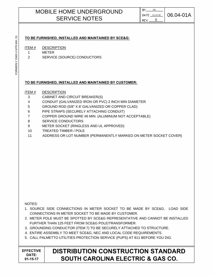
MOBILE HOME UNDERGROUND
SERVICE PEDESTAL
NOTES:
1. SEE DRAWING 06.04-01A FOR A LIST OF ITEMS AND NOTES.
2. SEE DRAWINGS 06.01-01 AND 06.01-02 FOR GENERAL INFORMATION AND NOTES.
3. SEE DRAWING 06.01-03 FOR MOBILE HOME SERVICE DETAILS.
JAL
11-14-16
0
06.04-01BF
OR
ME
RLY
D
WG
# M
TR
-M
H, S
2
DISTRIBUTION CONSTRUCTION STANDARD
SOUTH CAROLINA ELECTRIC & GAS CO.
EFFECTIVE
DATE:
01-15-17
8
2
1
3
4
5
10
9
7
6
11
6' - 0" MAX
4' - 6" MIN
30" MIN
SCE&G SOURCE
4' MIN
CUSTOMER LOAD
WIRE DEPTH AS
REQUIRED BY CODE
FRONT VIEW SIDE VIEW BACK VIEW
101
1
MINIMUM
REQUIREMENT
FOR METER IS
4" X 6" TREATED
TIMBER
GROUND IN
ACCORDANCE WITH
LOCAL BUILDING
CODES
3

TEMPORARY UNDERGROUND
SERVICE NOTES
JAL
03-23-17
1
06.04-02A
DISTRIBUTION CONSTRUCTION STANDARD
SOUTH CAROLINA ELECTRIC & GAS CO.
EFFECTIVE
DATE:
03-23-17
TO BE FURNISHED, INSTALLED AND MAINTAINED BY SCE&G:
ITEM # DESCRIPTION
1 METER
2 PAD MOUNTED TRANSFORMER
TO BE FURNISHED, INSTALLED AND MAINTAINED BY CUSTOMER:
ITEM # DESCRIPTION
3 CIRCUIT BREAKER(S) AND RECEPTACLES
4 CONDUIT (GALVANIZED IRON OR PVC) 2 INCH MIN DIAMETER
5 GROUND ROD (5/8" X 8' GALVANIZED OR COPPER CLAD)
6 PIPE STRAPS (SECURELY ATTACHING CONDUIT)
7 COPPER GROUND WIRE #6 MIN. (ALUMINUM NOT ACCEPTABLE)
8 SERVICE CONDUCTORS #4 MIN.-#2 MAX. (FROM TRANSFORMER TO METER SOCKET)
9 METER SOCKET (RINGLESS AND UL APPROVED)
10 CONDUIT SERVICE WEATHERHEAD
11 TREATED TIMBER / POLE (4X4 TIMBER OR 5 INCH DIAMETER AT POLE TOP MINIMUM)
NOTES:
1. SOURCE AND LOAD SIDE CONNECTIONS IN METER SOCKET TO BE MADE BY CUSTOMER.
2. TEMPORARY SERVICE POLE TO BE INSTALLED FRONT (DOOR/PAD LOCK) RIGHT SIDE OF
TRANSFORMER AND NO CLOSER THAN 4 FEET.
3. TEMPORARY SERVICE POLE CAN BE CONNECTED AT SECONDARY HAND-HOLE OR
PEDESTAL.
4. CUSTOMER TO INSTALL SERVICE CONDUCTOR (ITEM 8) MINIMUM OF 12 INCHES BELOW
GRADE AND TO WITHIN 1 FOOT OF POINT OF SERVICE (IE., TRANSFORMER). WITHIN 1 FOOT
OF TRANSFORMER, SCE&G REQUIRES ADDITIONAL 10 FEET OF SERVICE CONDUCTOR TO
MAKE CONNECTION.
5. GROUNDING CONDUCTOR (ITEM 7) TO BE SECURELY ATTACHED TO STRUCTURE.
6. ENTIRE ASSEMBLY TO MEET SCE&G, N.E.C. AND LOCAL CODE REQUIREMENTS.
7. CALL PALMETTO UTILITIES PROTECTION SERVICE (PUPS) AT 811 BEFORE YOU DIG.
RE
V. 1 (03/23/17) - U
PD
AT
ED
IT
EM
# 11 (4X
4)

TEMPORARY UNDERGROUND
SERVICE POLE / PEDESTAL
NOTES:
1. SEE DRAWING 06.04-02A FOR A LIST OF ITEMS AND NOTES.
2. SEE DRAWINGS 06.01-01 AND 06.01-02 FOR GENERAL INFORMATION AND NOTES.
JAL
11-14-16
0
06.04-02BF
OR
ME
RLY
D
WG
# M
TR
-T
2, S
2
DISTRIBUTION CONSTRUCTION STANDARD
SOUTH CAROLINA ELECTRIC & GAS CO.
EFFECTIVE
DATE:
01-15-17
3
6' - 0" MAX
4' - 6" MIN
4' MIN
4' MIN
1' MIN.
1' MIN.
4' MIN
1' MIN.
1' MIN.
6' - 0" MAX
4' - 6" MIN
4' MIN
1
1
2
2
3
4
4
4
5
5
6
6
6
7
7
8
8
10
8' MIN.
11
11
POLE
PEDESTAL
GROUND IN
ACCORDANCE
WITH LOCAL
BUILDING CODES
GROUND IN ACCORDANCE WITH
LOCAL BUILDING CODES
9
9
SERVICE POLE LOCATION
(TYPICAL)
TRANSFORMER FRONT
(PAD LOCK)
4 FEET
SERVICE POLE
AREA

NON-JOINT USE TRENCHING DETAIL
JAL
06-09-17
0
16.01-05
FO
RM
ER
LY
D
WG
# T
-2
DISTRIBUTION CONSTRUCTION STANDARD
SOUTH CAROLINA ELECTRIC & GAS CO.
6"
30"
36"
30"
MAIN TRENCH
SERVICE TRENCH
SOIL BACKFILL
CLEAN DIRT OR SAND
SECONDARY CABLE
PRIMARY CABLE
NOTES:
1. ALL DIMENSIONS ARE MINIMUMS.
2. THE BOTTOM OF THE TRENCH SHALL BE UNDISTURBED, TAMPED, OR RELATIVELY SMOOTH EARTH. WHERE THE
EXCAVATION IS IN ROCK, THE CONDUIT/CABLE SHALL BE LAID ON A PROTECTIVE LAYER OF CLEAN WELL-TAMPED
BACKFILL.
3. BACKFILL WITHIN SIX INCHES OF THE CONDUIT/CABLE SHALL BE FREE OF MATERIAL WITH SHARP EDGES. BACKFILL SHALL
BE ADEQUATELY COMPACTED (MACHINE COMPACTION SHALL NOT BE USED WITHIN SIX INCHES OF THE CABLE/CONDUIT).
30"
>48"
SOIL BACKFILL
CLEAN DIRT OR SAND
SECONDARY CABLE
PRIMARY CABLE
WATER, SEWER, DRAINAGE, ETC.
6"
<42"
WATER, SEWER, DRAINAGE, ETC.
12"
30"
42"
TO
48"
WATER, SEWER, DRAINAGE, ETC.
SECONDARY CABLE
PRIMARY CABLE
SOIL BACKFILL
CLEAN DIRT OR SAND
12"
12"
12"
6"
EFFECTIVE
DATE:
08-07-17

ROAD CROSSING DETAIL
NOTES:
1. ALL DIMENSIONS ARE MINIMUMS.
2. GRAY SCHEDULE 40 ELECTRICAL CONDUIT IS REQUIRED FOR ALL ROAD AND PARKING LOT CROSSINGS. CONDUIT
SHALL BE CONTINUOUS WITH GLUED JOINTS, PULL STRING INSTALLED, AND CAPPED AT EACH END. CAPPED END
LOCATIONS TO BE IDENTIFIED BY A RED PVC MARKER, I.E., CONDUIT STUB PAINTED RED.
3. CONDUIT MUST TERMINATE WITHIN THE SCE&G ELECTRIC EASEMENT OF THE PROPERTY LOT (TERMINIATING IN
ROAD RIGHT-OF-WAY IS UNACCEPTABLE).
4. SEE DRAWING 16.01-02 FOR VERTICAL CLEARANCES.
JAL
06-12-17
0
16.01-06
FO
RM
ER
LY
D
WG
# T
-5
DISTRIBUTION CONSTRUCTION STANDARD
SOUTH CAROLINA ELECTRIC & GAS CO.
CROSSING
R/W
SECONDARY CONDUIT
PRIMARY CONDUIT
R/W
PVC MARKER
30"
36"
LOT 47
P
LP
L
P
L
P
L
P
L
P
L
ROAD
(50' R/W)
ROAD (50' R/W)
36"
SOIL BACKFILL
CLEAN DIRT OR SAND
PRIMARY CABLE
8'
WATER, SEWER,
DRAINAGE, ETC.
PARALLEL CLEARANCE
ROAD CROSSINGS
PVC MARKER
30"
36"
LOT 46
LOT 50
LOT 49
LOT 48
EFFECTIVE
DATE:
08-07-17

METER SOCKETS
METER SOCKETS
METER SOCKETS ARE FURNISHED, INSTALLED AND MAINTAINED BY THE CUSTOMER. ALL
METER SOCKETS SHALL BE RINGLESS, HAVE UL APPROVAL, AND COMPLY WITH ANSI C12.7
SPECIFICATIONS.
METER SOCKETS SHALL BE INSTALLED WHERE READILY ACCESSIBLE (REFERENCE SECTION 5
OF THE SCE&G ELECTRIC SERVICE AND METER INSTALLATIONS MANUAL). METER SOCKET
LOCATIONS SHALL BE APPROVED BY AN SCE&G REPRESENTATIVE PRIOR TO INSTALLATION.
100 AMP METER SOCKETS ARE FOR LOW CURRENT APPLICATIONS ONLY (TEMPORARY
SERVICES, CATV AMPLIFIER SERVICES, TRAFFIC SIGNAL LIGHTS, AND BILLBOARD SERVICES).
METER SOCKET CONNECTIONS
ALL NEW 100 AMP AND 200 AMP SELF-CONTAINED METER SOCKETS MAY BE EQUIPPED WITH
LAY-IN MECHANICAL TERMINALS OR STUDS FOR ONE-HOLE COMPRESSION LUGS.
COMPRESSION LUGS ARE PROVIDED BY THE CUSTOMER AND SHALL BE APPROVED BY SCE&G
(SEE SECTION 14). ALL FOUR-GANG OR LARGER METER SOCKETS SHALL HAVE TWO (2) LAY-IN
CONNECTIONS ON EACH TERMINAL IN THE CENTER WIRING COMPARTMENT.
OVERHEAD SERVICE: SOURCE AND LOAD WIRES ARE TERMINATED IN METER SOCKET BY
THE CUSTOMER.
UNDERGROUND SERVICE: CONDUIT TERMINATES AT METER SOCKET ON BOTTOM LEFT OR
BOTTOM RIGHT (NEVER IN THE CENTER); SOURCE WIRES ARE
TERMINATED BY SCE&G; LOAD WIRES ARE TERMINATED BY THE
CUSTOMER.
NOTES:
1. ALL INSTALLATIONS SHALL MEET SCE&G, NEC AND LOCAL CODE REQUIREMENTS.
2. SOURCE CONDUCTORS SHALL ALWAYS BE TERMINATED IN THE TOP SIDE OF THE METER. FOR
CUSTOMER GENERATION APPLICATIONS, I.E., SOLAR, SCE&G IS ALWAYS THE SOURCE/LINE AND
THE CUSTOMER IS ALWAYS THE LOAD.
3. METER SOCKETS FOR UNDERGROUND MUST BE SIZED TO ACCOMMODATE THE BEND RADIUS
OF THE CONDUCTORS BEING INSTALLED (REFERENCE NEC TABLE 312.6(B)).
4. METERED AND UNMETERED CONDUCTORS SHALL NOT OCCUPY THE SAME RACEWAY.
5. ONLY SCE&G OWNED EQUIPMENT IS ALLOWED IN METER SOCKET.
JAL
07-10-17
1
19.01-01
DISTRIBUTION CONSTRUCTION STANDARD
SOUTH CAROLINA ELECTRIC & GAS CO.
EFFECTIVE
DATE:
08-07-17
OVERHEAD
SERVICE
UNDERGROUND
SERVICE
SOURCE
CONDUIT
RE
V. 1 (07/10/17) - A
DD
ED
N
OT
E 5

METER CLEARANCE REQUIREMENTS
NOTES:
1. SEE DRAWING 19.01-01 FOR GENERAL INFORMATION AND NOTES.
2. PERMANENT AND/OR TEMPORARY OBSTRUCTIONS ARE NOT PERMITTED WITHIN THREE
FEET IN ANY DIRECTION OF AN ELECTRIC METER.
3. OBSTRUCTIONS INCLUDE, BUT ARE NOT LIMITED TO TREES, SHRUBS, HVAC UNITS,
GENERATORS, WALLS, FENCES, GAS METERS AND/OR BUILDINGS.
4. SEE DRAWING 19.01-05 FOR GANGED METER SOCKETS.
JAL
07-10-17
1
19.01-03
DISTRIBUTION CONSTRUCTION STANDARD
SOUTH CAROLINA ELECTRIC & GAS CO.
EFFECTIVE
DATE:
06-05-17
3' 3'
3'
6'-0" MAX
4'-6" MIN
3'
3' 3'
SEE NOTE 3
RE
V. 1 (07/10/17) - A
DD
ED
G
AS
M
ET
ER
S T
O N
OT
E 3
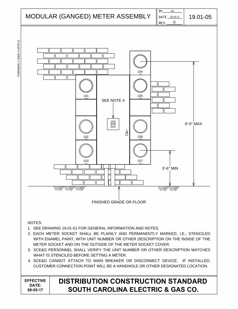
MODULAR (GANGED) METER ASSEMBLY
NOTES:
1. SEE DRAWING 19.01-01 FOR GENERAL INFORMATION AND NOTES.
2. EACH METER SOCKET SHALL BE PLAINLY AND PERMANENTLY MARKED, I.E., STENCILED
WITH ENAMEL PAINT, WITH UNIT NUMBER OR OTHER DESCRIPTION ON THE INSIDE OF THE
METER SOCKET AND ON THE OUTSIDE OF THE METER SOCKET COVER.
3. SCE&G PERSONNEL SHALL VERIFY THE UNIT NUMBER OR OTHER DESCRIPTION MATCHES
WHAT IS STENCILED BEFORE SETTING A METER.
4. SCE&G CANNOT ATTACH TO MAIN BREAKER OR DISCONNECT DEVICE. IF INSTALLED,
CUSTOMER CONNECTION POINT WILL BE A HANDHOLE OR OTHER DESIGNATED LOCATION.
JAL
05-03-17
0
19.01-05
FO
RM
ER
LY
D
WG
# M
TR
-G
DISTRIBUTION CONSTRUCTION STANDARD
SOUTH CAROLINA ELECTRIC & GAS CO.
ON
OFF
FINISHED GRADE OR FLOOR
6'-0" MAX
3'-6" MIN
SEE NOTE 4
101
102
103 107
106
105
104
EFFECTIVE
DATE:
06-05-17

SINGLE-PHASE 120V 2W METER
NOTE:
1. SEE DRAWING 19.01-01 FOR GENERAL INFORMATION AND NOTES.
JAL
04-24-17
0
19.02-01F
OR
ME
RLY
D
WG
# M
TR
-1, S
1
DISTRIBUTION CONSTRUCTION STANDARD
SOUTH CAROLINA ELECTRIC & GAS CO.
A
N
X
3
X
1
H
1
H
2
X
2
A
C B
D
N
2 WIRE METER
100 AMP - 120V
FORM 1S METER
L
1
JUMPER
REQUIRED
120V
L
2
240V 120V
3 WIRE METER
100 AMP - 120V
FORM 2S METER
EFFECTIVE
DATE:
06-05-17

SINGLE-PHASE 120/240V
3W METER (200 AMPS)
JAL
04-24-17
0
19.02-02AF
OR
ME
RLY
D
WG
# M
TR
-1, S
1
DISTRIBUTION CONSTRUCTION STANDARD
SOUTH CAROLINA ELECTRIC & GAS CO.
NOTE:
1. SEE DRAWING 19.01-01 FOR GENERAL INFORMATION AND NOTES.
A
N
X
3
X
1
H
1
H
2
X
2
A
C B
D
120V
N
3 WIRE METER
200 AMP - 120/240V
FORM 2S METER
L
1
L
2
240V 120V
EFFECTIVE
DATE:
06-05-17

SINGLE-PHASE 120/240V
3W METER (201 - 600 AMPS)
JAL
04-24-17
0
19.02-02BF
OR
ME
RLY
D
WG
# M
TR
-1, S
1 &
S
2
DISTRIBUTION CONSTRUCTION STANDARD
SOUTH CAROLINA ELECTRIC & GAS CO.
NOTE:
1. SEE DRAWING 19.01-01 FOR GENERAL INFORMATION AND NOTES.
A
N
X
3
X
1
H
1
H
2
X
2
A
C B
D
120V
N
3 WIRE METER
201 - 600 AMPS - 120/240V
FORM 2K METER
L
1
L
2
240V 120V
K-4UT SOCKET
AL
TE
RN
AT
E
LO
CA
TIO
N
K-4SW SOCKET
EFFECTIVE
DATE:
06-05-17