Embed Size (px)
Citation preview
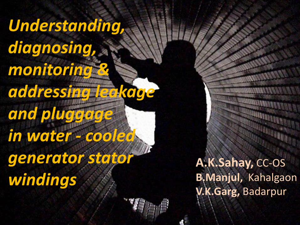
Understanding, diagnosing, monitoring & addressing leakage and pluggage in water - cooled generator stator windings
A.K.Sahay, CC-OS B.Manjul, Kahalgaon V.K.Garg, Badarpur
Reliability of generator is dependent on electrical and mechanical integrity of stator winding According to survey of manufacturer including GE, Siemens / Westinghouse and Electrosila , the most probable age of water cooled stator windings is approximately 25-30 yrs. Considering the age of our first generation units , it is felt that it prudent to have a closer look of this system and some recent advances that has taken place in this area needs to be taken into consideration Early detection of water cooled leakages can significantly reduce the risk of failure associated cost. Key is proper understanding and monitoring of associated parameters (especially Chemistry parameters) of the system.
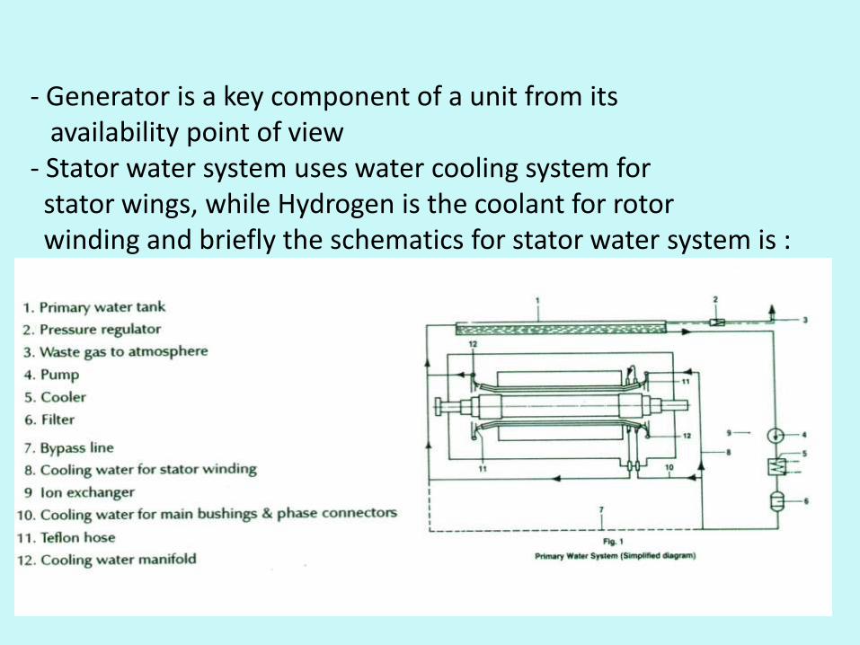
- Generator is a key component of a unit from its availability point of view - Stator water system uses water cooling system for stator wings, while Hydrogen is the coolant for rotor winding and briefly the schematics for stator water system is :
•Reliability issues affecting generators - Water leakage of stator windings - Clogging in copper hallow conductors - Wedge looseness - Stator core looseness and hot spots - End-winding vibration Among these we shall dwell upon the first two points
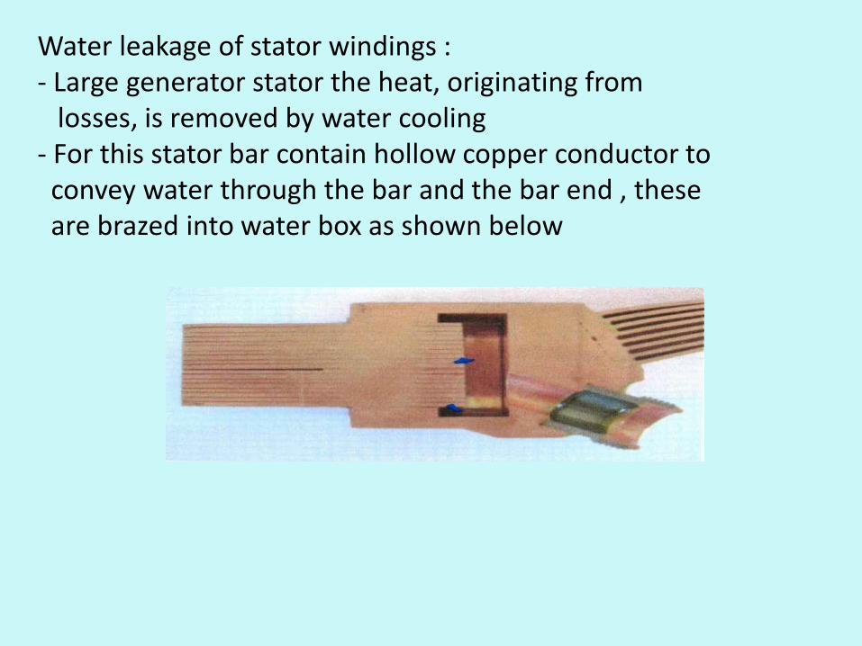
Water leakage of stator windings : - Large generator stator the heat, originating from losses, is removed by water cooling - For this stator bar contain hollow copper conductor to convey water through the bar and the bar end , these are brazed into water box as shown below
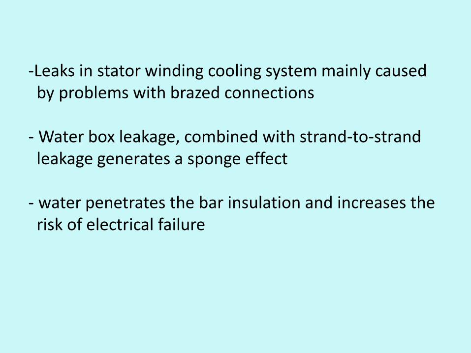
-Leaks in stator winding cooling system mainly caused by problems with brazed connections - Water box leakage, combined with strand-to-strand leakage generates a sponge effect - water penetrates the bar insulation and increases the risk of electrical failure
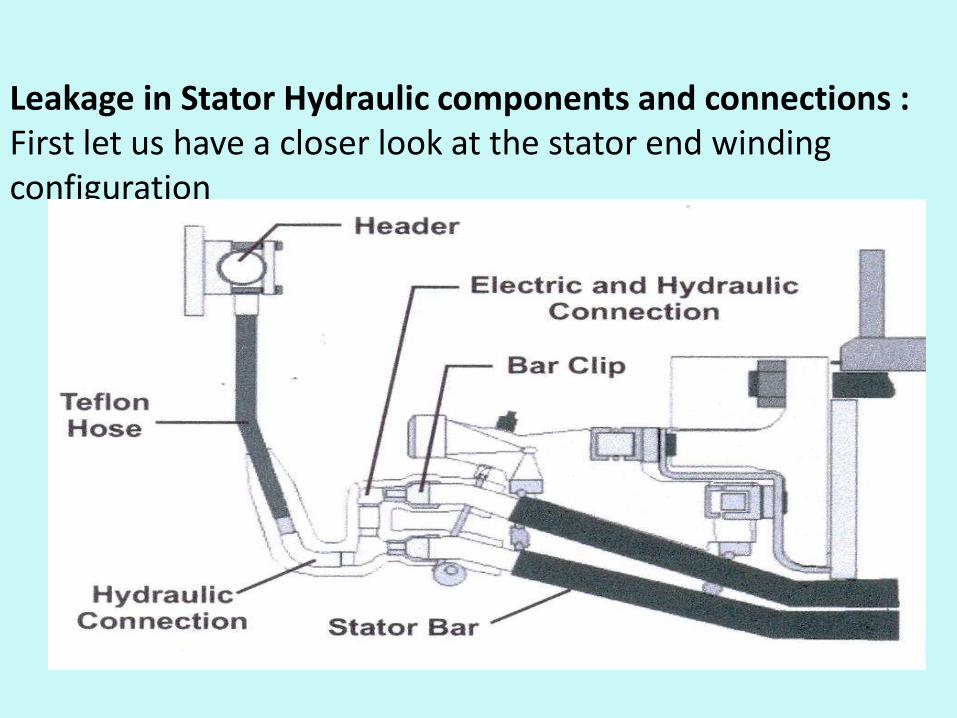
Leakage in Stator Hydraulic components and connections : First let us have a closer look at the stator end winding configuration
Leak may originate at any of the followings : - Copper tubings, Pipes, Pipings, elbows,fillings, sleeve joints, tube extension - Teflon hoses / hose fittings - Liquid cooled services loop brazes and connection rings Small leaks in these locations will not result in winding damage during normal operation as H2 gas Press. is maintained well above stator cooling water pressure. But small leaks pose problem during outage when generator is de-gassed and stator water system is left in operation Under those circumstance s the Press. Diff. force the leaking water into ground insulation.
Leaks in stator bar : a) Leaks in clip window braze b) Leaks through porosity especially with older units built with cast clips : Some of the hydraulic plumbing components used in older units with bottle clips were also cast which is vulnerable for leakage in localized area of high porosity c) Leaks in clip to strand braze : A leak process initiates in the braze alloy at the inner surface by Crevice corrosion mechanism. Under right conditions the leak can change to corrosive penetration of adjacent copper tubes.
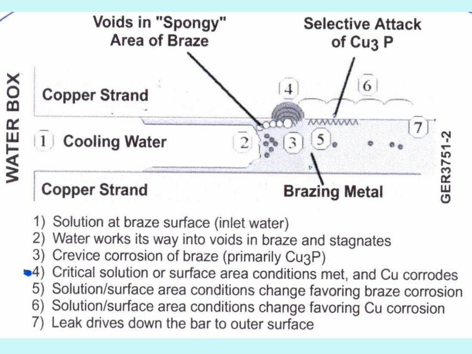
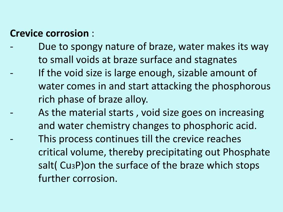
Crevice corrosion : - Due to spongy nature of braze, water makes its way to small voids at braze surface and stagnates - If the void size is large enough, sizable amount of water comes in and start attacking the phosphorous rich phase of braze alloy. - As the material starts , void size goes on increasing and water chemistry changes to phosphoric acid. - This process continues till the crevice reaches critical volume, thereby precipitating out Phosphate salt( Cu3P)on the surface of the braze which stops further corrosion.
-If the void size is good enough and the phosphoric acid inside this void come in contact with Copper strand, the attack by Phosphoric acid to Copper is a preferred reaction as compared to that of braze and also the rate of reaction is also high. - The depth of copper is limited and constant ( approx. by 0.015 inch) partly by precipitation of Phosphate salt on Copper and partly by volume of liquid too large to maintain critical acid conc.
-This leads to attack of Phosphorous phase of braze material leading to formation of Phosphoric acid which again starts reacting with Copper. - This mechanism switches back and forth from Crevice to acid attack of copper as the leak path makes its way to the strand.
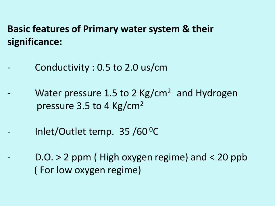
Basic features of Primary water system & their significance: - Conductivity : 0.5 to 2.0 us/cm - Water pressure 1.5 to 2 Kg/cm2 and Hydrogen pressure 3.5 to 4 Kg/cm2 - Inlet/Outlet temp. 35 /60 0C - D.O. > 2 ppm ( High oxygen regime) and < 20 ppb ( For low oxygen regime)
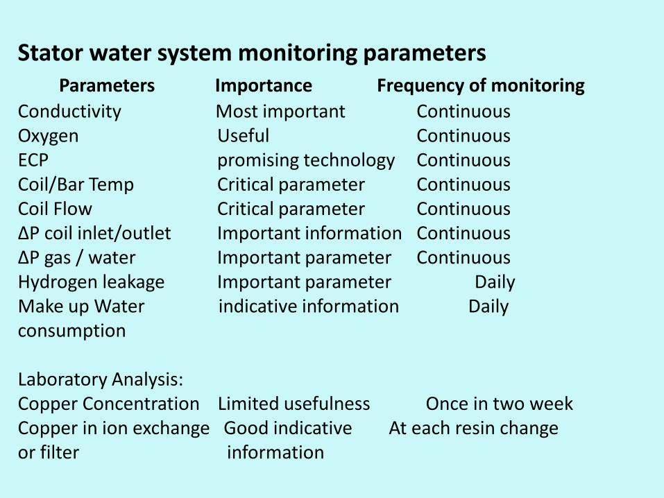
Stator water system monitoring parameters Parameters Importance Frequency of monitoring
Conductivity Most important Continuous Oxygen Useful Continuous ECP promising technology Continuous Coil/Bar Temp Critical parameter Continuous Coil Flow Critical parameter Continuous ∆P coil inlet/outlet Important information Continuous ∆P gas / water Important parameter Continuous Hydrogen leakage Important parameter Daily Make up Water indicative information Daily consumption Laboratory Analysis: Copper Concentration Limited usefulness Once in two week Copper in ion exchange Good indicative At each resin change or filter information
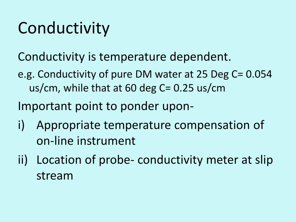
Conductivity
Conductivity is temperature dependent.
e.g. Conductivity of pure DM water at 25 Deg C= 0.054 us/cm, while that at 60 deg C= 0.25 us/cm
Important point to ponder upon-
i) Appropriate temperature compensation of on-line instrument
ii) Location of probe- conductivity meter at slip stream
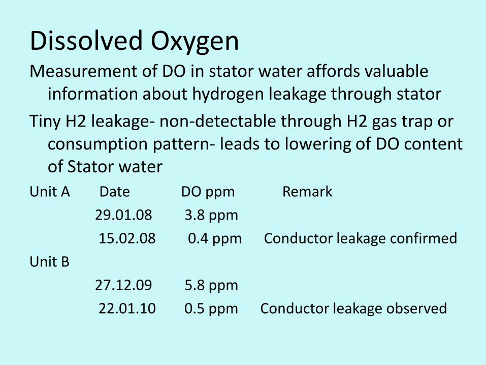
Dissolved Oxygen Measurement of DO in stator water affords valuable
information about hydrogen leakage through stator
Tiny H2 leakage- non-detectable through H2 gas trap or consumption pattern- leads to lowering of DO content of Stator water
Unit A Date DO ppm Remark
29.01.08 3.8 ppm
15.02.08 0.4 ppm Conductor leakage confirmed
Unit B
27.12.09 5.8 ppm
22.01.10 0.5 ppm Conductor leakage observed
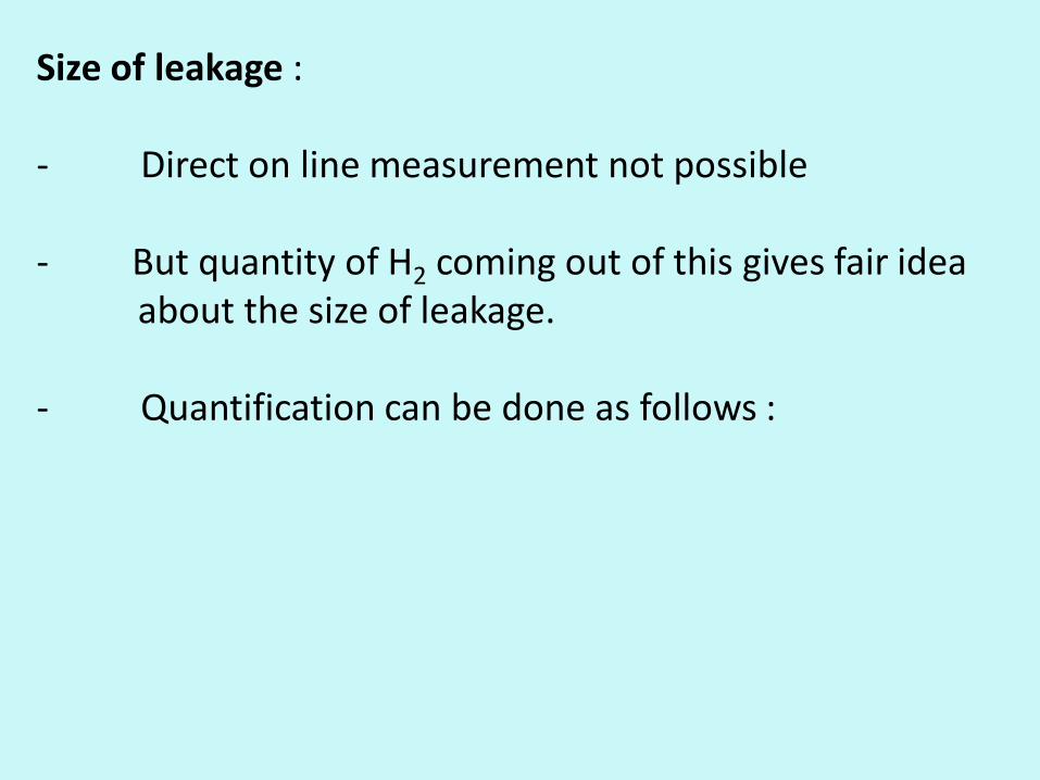
Size of leakage : - Direct on line measurement not possible - But quantity of H2 coming out of this gives fair idea about the size of leakage. - Quantification can be done as follows :
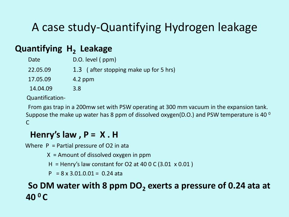
A case study-Quantifying Hydrogen leakage
Quantifying H2 Leakage Date D.O. level ( ppm)
22.05.09 1.3 ( after stopping make up for 5 hrs)
17.05.09 4.2 ppm
14.04.09 3.8
Quantification-
From gas trap in a 200mw set with PSW operating at 300 mm vacuum in the expansion tank. Suppose the make up water has 8 ppm of dissolved oxygen(D.O.) and PSW temperature is 40 0 C
Henry’s law , P = X . H Where P = Partial pressure of O2 in ata
X = Amount of dissolved oxygen in ppm
H = Henry’s law constant for O2 at 40 0 C (3.01 x 0.01 )
P = 8 x 3.01.0.01 = 0.24 ata
So DM water with 8 ppm DO2 exerts a pressure of 0.24 ata at 40 0 C
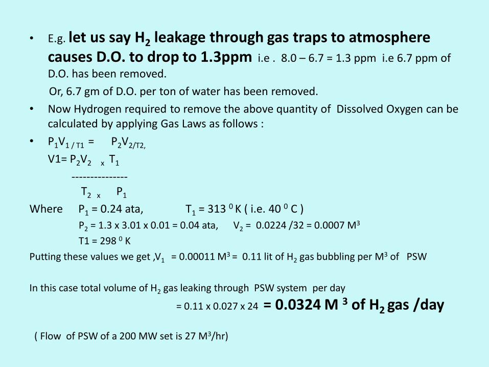
• E.g. let us say H2 leakage through gas traps to atmosphere causes D.O. to drop to 1.3ppm i.e . 8.0 – 6.7 = 1.3 ppm i.e 6.7 ppm of
D.O. has been removed.
Or, 6.7 gm of D.O. per ton of water has been removed.
• Now Hydrogen required to remove the above quantity of Dissolved Oxygen can be calculated by applying Gas Laws as follows :
• P1V1 / T1 = P2V2/T2,
V1= P2V2 x T1
--------------- T2 x P1
Where P1 = 0.24 ata, T1 = 313 0 K ( i.e. 40 0 C )
P2 = 1.3 x 3.01 x 0.01 = 0.04 ata, V2 = 0.0224 /32 = 0.0007 M3
T1 = 298 0 K
Putting these values we get ,V1 = 0.00011 M3 = 0.11 lit of H2 gas bubbling per M3 of PSW
In this case total volume of H2 gas leaking through PSW system per day
= 0.11 x 0.027 x 24 = 0.0324 M 3 of H2 gas /day
( Flow of PSW of a 200 MW set is 27 M3/hr)
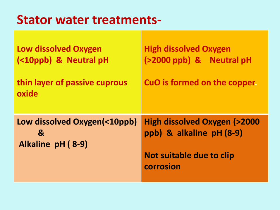
Stator water treatments- Low dissolved Oxygen (<10ppb) & Neutral pH thin layer of passive cuprous oxide
High dissolved Oxygen (>2000 ppb) & Neutral pH CuO is formed on the copper.
Low dissolved Oxygen(<10ppb) & Alkaline pH ( 8-9)
High dissolved Oxygen (>2000 ppb) & alkaline pH (8-9) Not suitable due to clip corrosion
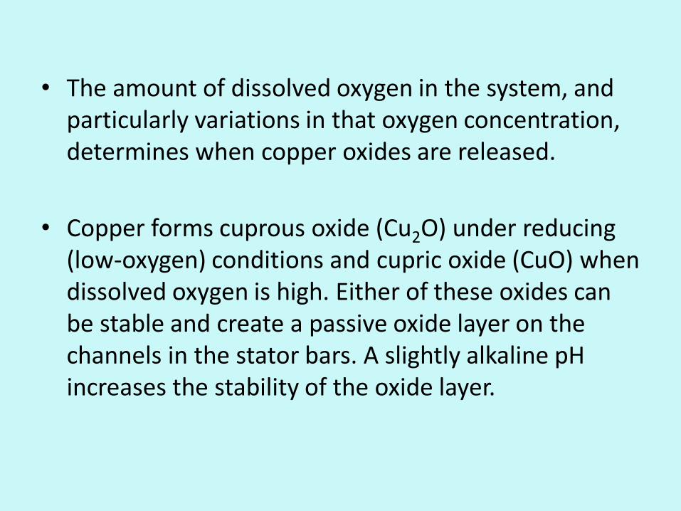
• The amount of dissolved oxygen in the system, and particularly variations in that oxygen concentration, determines when copper oxides are released.
• Copper forms cuprous oxide (Cu2O) under reducing (low-oxygen) conditions and cupric oxide (CuO) when dissolved oxygen is high. Either of these oxides can be stable and create a passive oxide layer on the channels in the stator bars. A slightly alkaline pH increases the stability of the oxide layer.
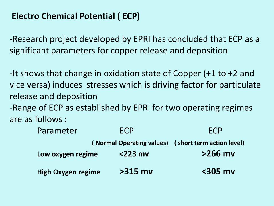
Electro Chemical Potential ( ECP) -Research project developed by EPRI has concluded that ECP as a significant parameters for copper release and deposition -It shows that change in oxidation state of Copper (+1 to +2 and vice versa) induces stresses which is driving factor for particulate release and deposition -Range of ECP as established by EPRI for two operating regimes are as follows : Parameter ECP ECP ( Normal Operating values) ( short term action level)
Low oxygen regime <223 mv >266 mv
High Oxygen regime >315 mv <305 mv
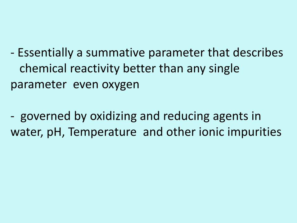
- Essentially a summative parameter that describes chemical reactivity better than any single parameter even oxygen - governed by oxidizing and reducing agents in water, pH, Temperature and other ionic impurities
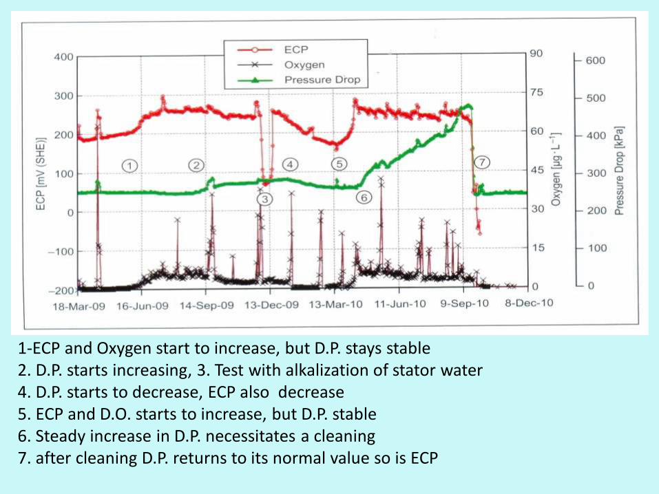
1-ECP and Oxygen start to increase, but D.P. stays stable 2. D.P. starts increasing, 3. Test with alkalization of stator water 4. D.P. starts to decrease, ECP also decrease 5. ECP and D.O. starts to increase, but D.P. stable 6. Steady increase in D.P. necessitates a cleaning 7. after cleaning D.P. returns to its normal value so is ECP
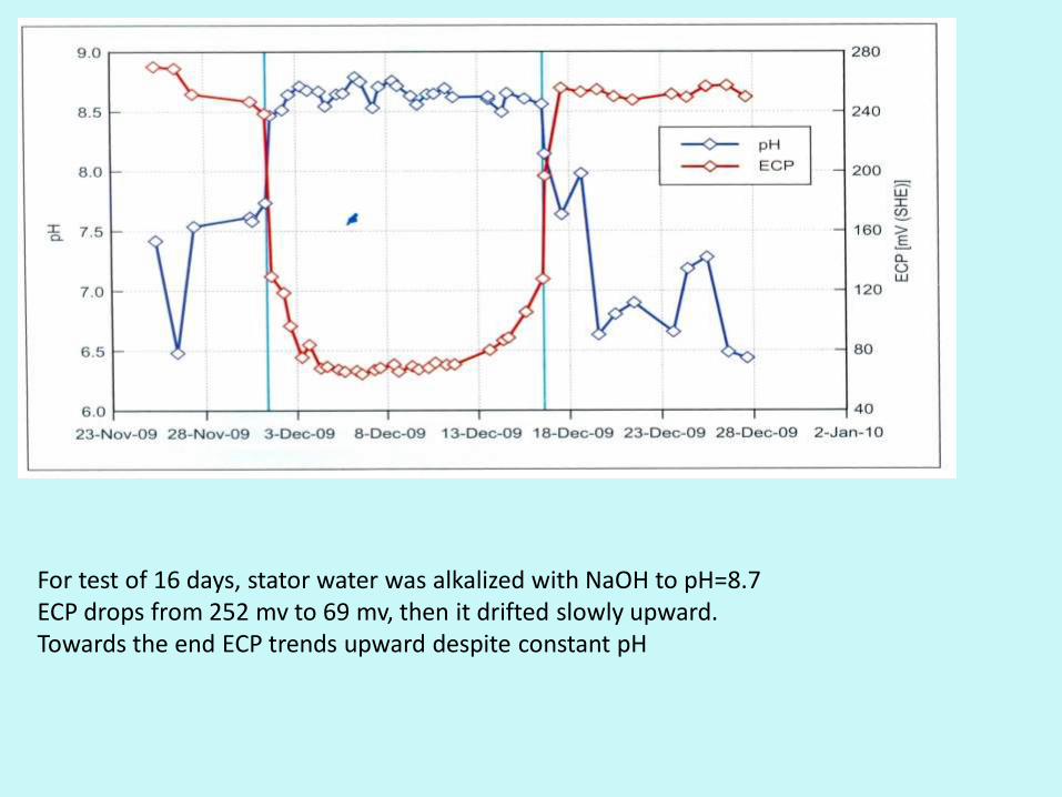
For test of 16 days, stator water was alkalized with NaOH to pH=8.7 ECP drops from 252 mv to 69 mv, then it drifted slowly upward. Towards the end ECP trends upward despite constant pH
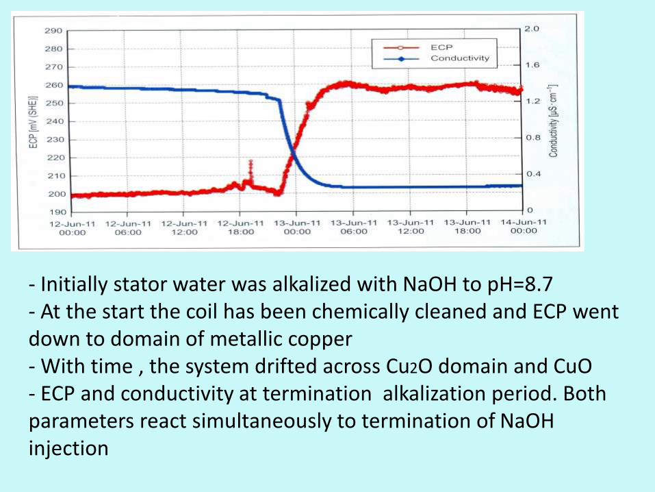
- Initially stator water was alkalized with NaOH to pH=8.7 - At the start the coil has been chemically cleaned and ECP went down to domain of metallic copper - With time , the system drifted across Cu2O domain and CuO - ECP and conductivity at termination alkalization period. Both parameters react simultaneously to termination of NaOH injection
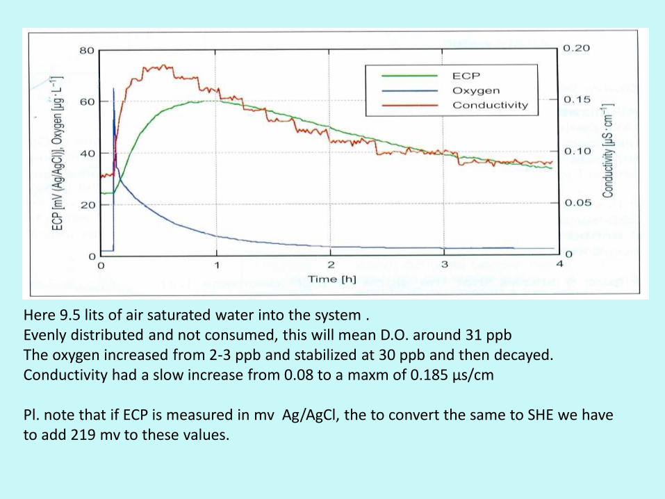
Here 9.5 lits of air saturated water into the system . Evenly distributed and not consumed, this will mean D.O. around 31 ppb The oxygen increased from 2-3 ppb and stabilized at 30 ppb and then decayed. Conductivity had a slow increase from 0.08 to a maxm of 0.185 µs/cm Pl. note that if ECP is measured in mv Ag/AgCl, the to convert the same to SHE we have to add 219 mv to these values.
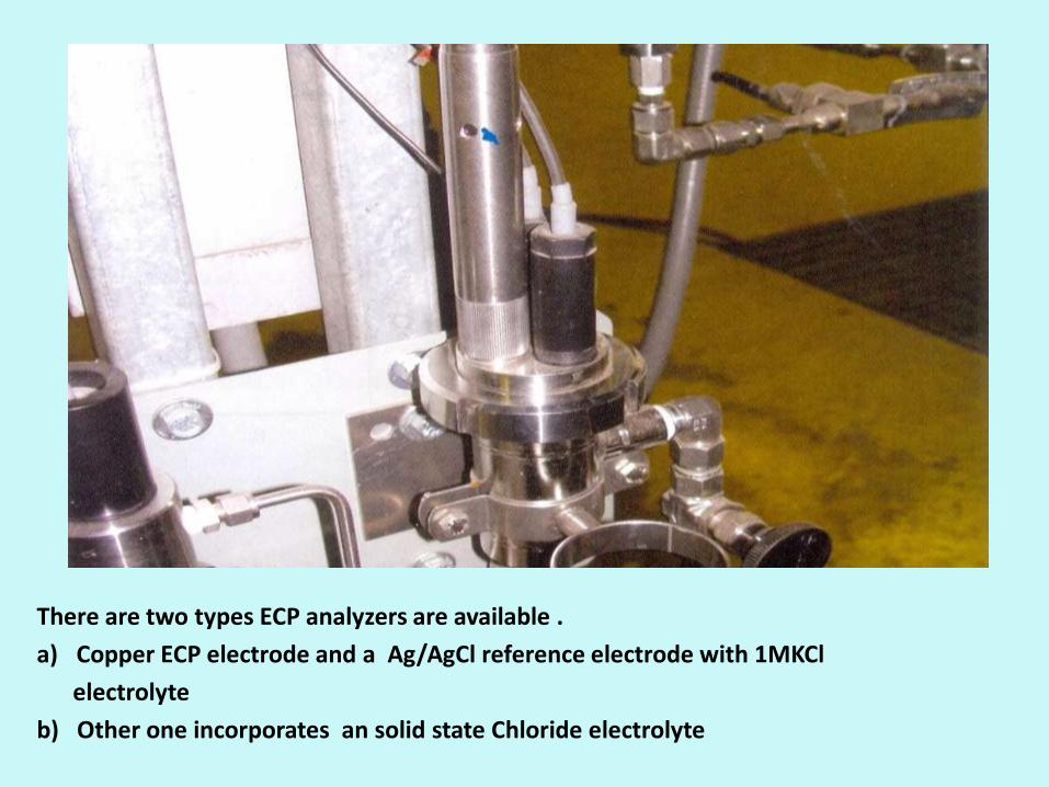
There are two types ECP analyzers are available .
a) Copper ECP electrode and a Ag/AgCl reference electrode with 1MKCl
electrolyte
b) Other one incorporates an solid state Chloride electrolyte
Addressing the plugging issues : - EPRI guidelines suggest following proactive measures to detect flow restrictions (i) Monitoring pressure drop, total stator water flow and individual bar flow (ii) Analysis of spent resins from SPU gives a fair indication of the quantity of Cu release from the system Cleaning method : (a ) Usually by EDTA as it removes only Copper Oxide and does not react with Cu metal ( b ) But limitation of this method is that if the strand is severely choked, this gentle organic acid may not be good enough and in that case cleaning to be done by 9% H2SO4
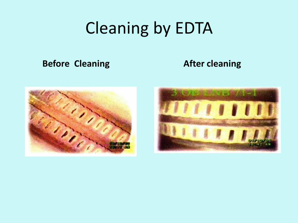
Cleaning by EDTA
Before Cleaning After cleaning
Preventing Pluggage : (a) On line ECP and D.O.Monitoring ( b) Off line Cu trend analysis From Spent SPU resins ( c ) For High oxygen regime : A large diameter vent to provide air access to the storage tank and forced aeration to the water tank (d) During shut down when stator water system is drained then it needs to be dried out with Nitrogen (Grade-1 ) quality
Conclusion : - After 25 years of service water cooled stator windings are prone to leakage - Monitoring leakage as reflected in lowering of D.O. in case of high oxygen regime is a reliable tool and it can be quantified as well - Latest experiment has shown that on line ECP monitoring shall be an important tool in assessing overall Chemistry of stator water system

Thank u very much