Embed Size (px)
Citation preview
4/25/2016
1
Understanding Gas Hydrates and its Utility for Energy Solutions
Rajnish Kumar
4/25/2016 1
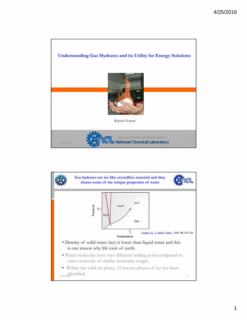
Gas hydrates are ice like crystalline material and they shares some of the unique properties of water
• Density of solid water (ice) is lower than liquid water and this
Cooper, A.I., J. Mater. Chem., 2000, 10, 207-234
y ( ) qis one reason why life exist of earth.
• Water molecules have very different boiling point compared to other molecule of similar molecular weight.
• Within the solid ice phase, 13 known phases of ice has been identified
4/25/2016 2
4/25/2016
2
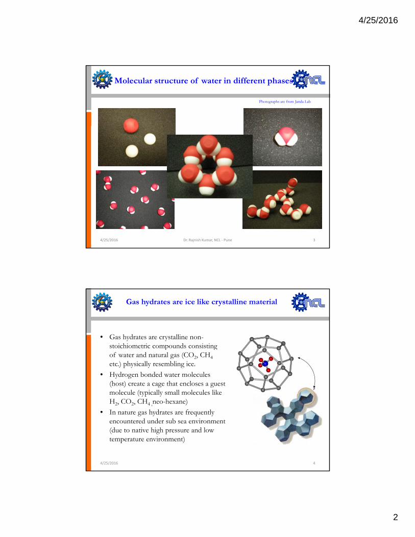
Molecular structure of water in different phases
Photographs are from Janda Lab
4/25/2016 Dr. Rajnish Kumar, NCL ‐ Pune 3
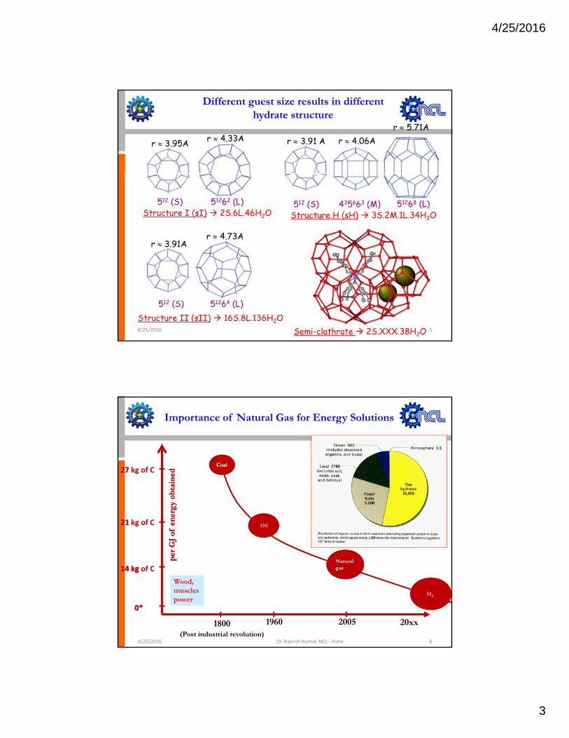
Gas hydrates are ice like crystalline material
• Gas hydrates are crystalline non-stoichiometric compounds consisting p gof water and natural gas (CO2, CH4etc.) physically resembling ice.
• Hydrogen bonded water molecules (host) create a cage that encloses a guest molecule (typically small molecules like H2, CO2, CH4 ,neo-hexane)I h d f l• In nature gas hydrates are frequently encountered under sub sea environment (due to native high pressure and low temperature environment)
4/25/2016 4
4/25/2016
3
Different guest size results in different hydrate structure
r ≈ 3.95A r ≈ 4.33A r ≈ 3.91 A r ≈ 4.06Ar ≈ 5.71A
Structure I (sI) 2S.6L.46H2O512 (S) 51262 (L)
Structure H (sH) 3S.2M.1L.34H2O512 (S) 435663 (M) 51268 (L)
r ≈ 3.91Ar ≈ 4.73A
Structure II (sII) 16S.8L.136H2O512 (S) 51264 (L)
4/25/2016 5Semi-clathrate 2S.XXX.38H2O
Importance of Natural Gas for Energy Solutions
27 27 kg of C
ned
ned
CoalCoal
21 21 kg of C
per
GJ
of e
ner
gy
obta
inp
er G
J of
en
erg
y ob
tain
Oil
Natural
1800(Post industrial revolution)
14 kg 14 kg of C
2005
Wood, muscles power
20xx1960
0*0*
gas
H2
4/25/2016 Dr. Rajnish Kumar, NCL ‐ Pune 6
4/25/2016
4
Clathrate Hydrates in Nature
• Natural gas is a mixture of mainly methane (90-99%), ethane (0-10%), propane (0-6%) & CO2 (0-5%) etc.
• Both pure methane and natural gas hydrates exist in the natural world (not only on earth but also on other planets)
• Large quantity of methane hydrate exist on earth either in permafrost or under the sea bed along continental margin
• Gas hydrates are a good energy resource but it can also be a potential geo y g gy p ghazard.
• Methane is 21 times more potent green house gas than CO2 and due to rise in global warming, methane in natural hydrates can decompose and create runaway effect
4/25/2016 Dr. Rajnish Kumar, NCL ‐ Pune 7
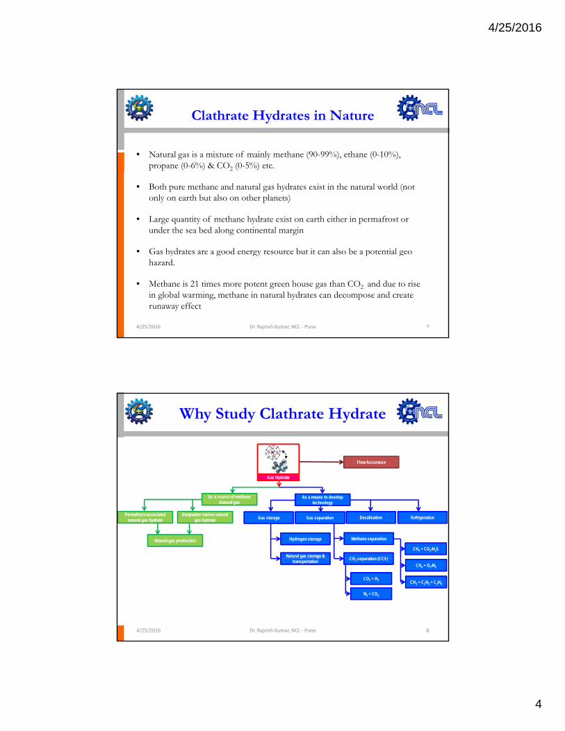
Why Study Clathrate Hydrate
• Understanding the hydrate at molecular level and at what is the right temperature and pressure zone where these hydrates can exist.
Flow Assurance
right temperature and pressure zone where these hydrates can exist.
• Understanding the mechanism of hydrate formation and decomposition
• Potentially a sustainable energy source while still being a potential geo hazard and role in global warming
Gas Hydrate
As a source of methane /natural gas
As a means to develop technology
Permafrost-associatednatural gas hydrate
Deepwater marine natural gas hydrate Gas storage Gas separation Desalination Refrigeration
Hydrogen storage
Natural gas storage &
Methane separation
CO separation (CCS)
CH4 + CO2/H2S
Natural gas production
• Safety in deep oil drilling operations
• Other technological applications and energy solutions like gas separation, methane storage and transportation
4/25/2016 Dr. Rajnish Kumar, NCL ‐ Pune 8
transportation CO2 separation (CCS)CH4 + O2/N2
CH4 + C2H6 + C3H8CO2 + H2
N2 + CO2
4/25/2016
5
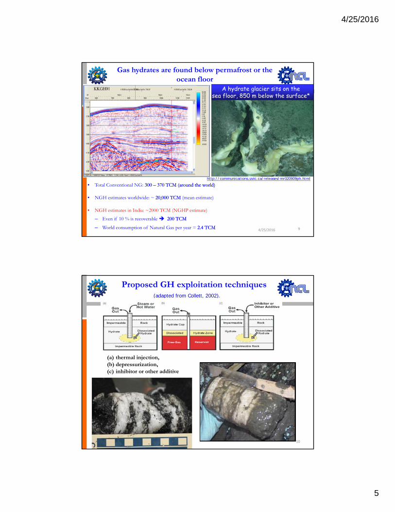
Gas hydrates are found below permafrost or the ocean floor
A hydrate glacier sits on the sea floor, 850 m below the surface*
Methane hydrate samples
http://communications uvic ca/releases/mr020909ph htmlhttp://communications.uvic.ca/releases/mr020909ph.html
4/25/2016
• Total Conventional NG: 300 300 –– 370 TCM (around the world)370 TCM (around the world)
• NGH estimates worldwide: ~ 20,000 TCM 20,000 TCM (mean estimate)
• NGH estimates in India: ~2000 TCM (NGHP estimate)
– Even if 10 % is recoverable 200 TCM200 TCM
– World consumption of Natural Gas per year = 2.4 TCM2.4 TCM 9
(adapted from Collett, 2002).
Proposed GH exploitation techniques
(a) thermal injection, (b) depressurization, (c) inhibitor or other additive
4/25/2016 10
4/25/2016
6
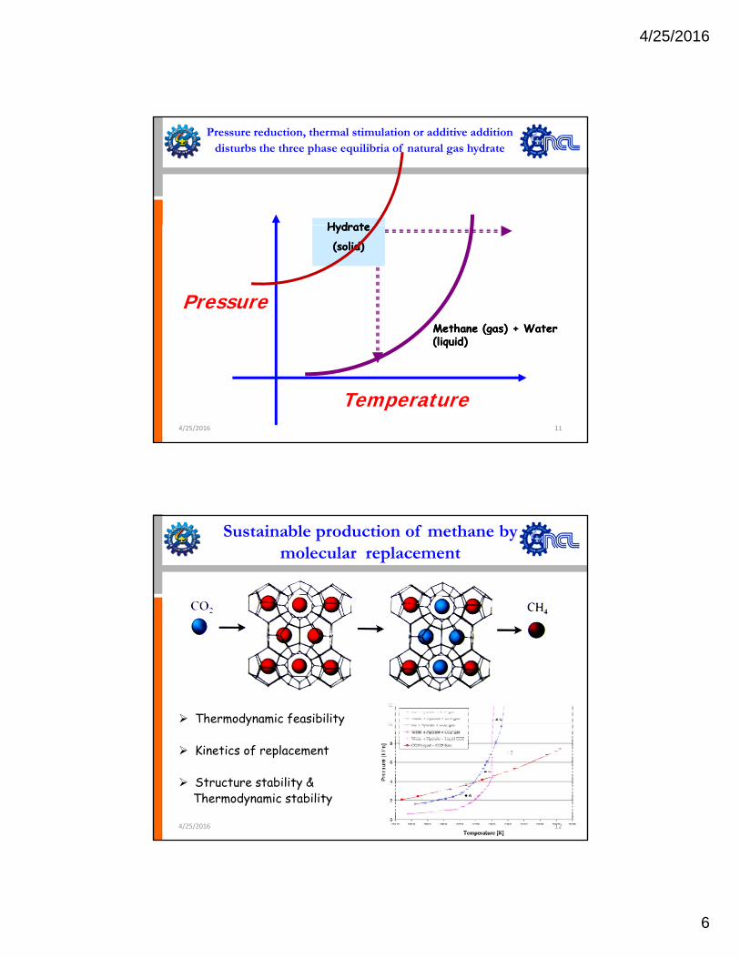
Pressure reduction, thermal stimulation or additive addition disturbs the three phase equilibria of natural gas hydrate
HydrateHydrate
PressureMethane (gas) + Water Methane (gas) + Water
HydrateHydrate
(solid)(solid)
Temperature
(g )(g )(liquid)(liquid)
4/25/2016 11
Sustainable production of methane by molecular replacement
Thermodynamic feasibility
Kinetics of replacement
Structure stability &Thermodynamic stability
4/25/2016 12
4/25/2016
7
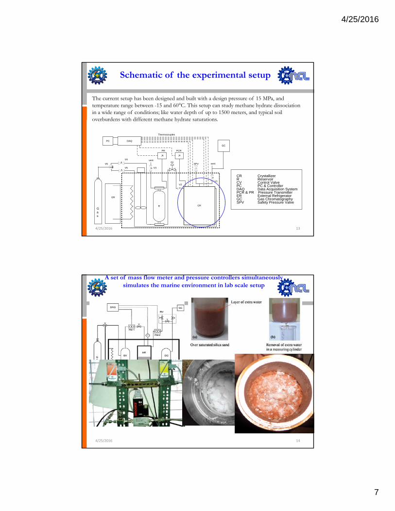
Schematic of the experimental setup
The current setup has been designed and built with a design pressure of 15 MPa, andtemperature range between -15 and 60°C. This setup can study methane hydrate dissociationin a wide range of conditions; like water depth of up to 1500 meters, and typical soiloverburdens with different methane hydrate saturations
PR PCR
GC
DAQ
Thermocouples
PC
V5 V3
V4cv
CR CrystallizerR R i
ventventV6 SPV
overburdens with different methane hydrate saturations.
CRR
ER
Gas
V1V2
R ReservoirCV Control ValvePC PC & ControllerDAQ Data Acquisition SystemPCR & PR Pressure TransmitterER External RefrigeratorGC Gas ChromatographySPV Safety Pressure Valve
4/25/2016 13
A set of mass flow meter and pressure controllers simultaneously simulates the marine environment in lab scale setup
4/25/2016 14
4/25/2016
8
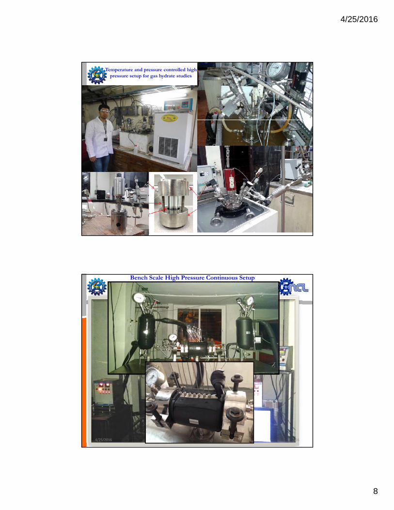
Temperature and pressure controlled high pressure setup for gas hydrate studies
4/25/2016 15
Bench Scale High Pressure Continuous Setup for Studying Methane Decomposition Kinetics at sub-Sea
Environment in Presence of Identified Additives
4/25/2016 16
4/25/2016
9
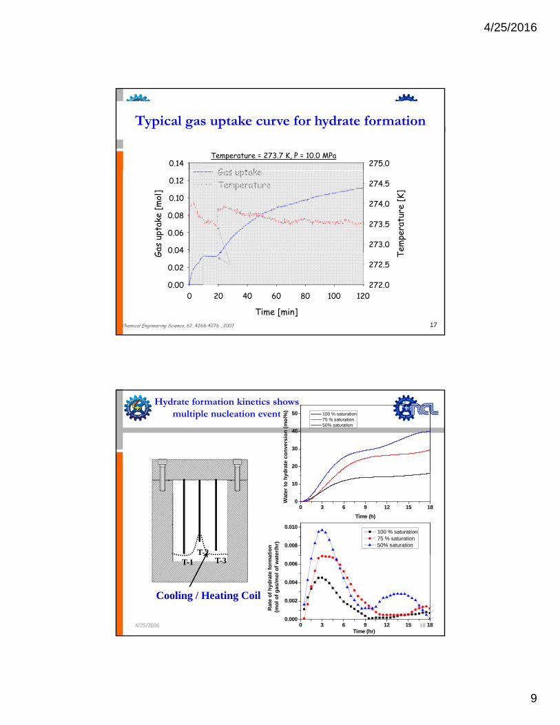
Hydrate formation is exothermicHydrate formation is a crystallization process
0.14 275.0G s pt k
Temperature = 273.7 K, P = 10.0 MPa
Typical gas uptake curve for hydrate formation
Gas
upta
ke [m
ol]
0.04
0.06
0.08
0.10
0.12
Tem
pera
ture
[K]
273.0
273.5
274.0
274.5Gas uptakeTemperature
17
Time [min]
0 20 40 60 80 100 120
G
0.00
0.02
0.04 T
272.0
272.5(induction time = 19.0 min)
Chemical Engineering Science, 62, 4268-4276 , 2007
Hydrate formation kinetics shows multiple nucleation event
20
30
40
50
drat
e co
nver
sion
(mol
%)
100 % saturation 75 % saturation 50% saturation
T-2
0 3 6 9 12 15 180
10
Wat
er to
hyd
Time (h)
0.008
0.010
tion
er/h
r)
100 % saturation 75 % saturation 50% saturation
4/25/2016
Cooling / Heating Coil
T-1 T-3T 2
0 3 6 9 12 15 180.000
0.002
0.004
0.006
Rat
e of
hyd
rate
form
at (m
ol o
f gas
/mol
of w
ate
Time (hr)18
4/25/2016
10
Conclusion from lab scale measurements
Methane recovery through thermal stimulation alone is possibleKinetics of hydrate decomposition is lumped kinetics
Decomposition of methane hydrate and its recovery by depressurization alone(without any thermal stimulation) does not self sustain.
In absence of thermal stimulation partial recovery of methane is obtained at slower kinetics
CH4 recovery by CO2 replacement is technically feasible, however focus shouldnot only be on the kinetics of methane replacement but also on overallmethane recoverymethane recovery
Still the question remains, what is the mechanism for such replacement? And what drives thereplacement ?
4/25/2016 19
Understanding gas hydrate & methane recovery at molecular level
• Understanding the structure and cage dynamics of gash d t th h t t f th t l ti l t lhydrates through state of the art analytical tools
• Understanding molecular level replacement kineticsthrough molecular dynamics simulation of hydrateformation and decomposition.
4/25/2016 20
4/25/2016
11
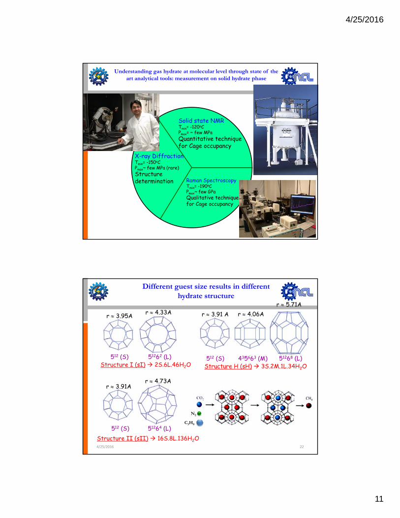
Understanding gas hydrate at molecular level through state of the art analytical tools: measurement on solid hydrate phase
Solid state NMRSolid state NMRTmin= -120oC Pmax= ~ few MPaQuantitative techniquefor Cage occupancy
Raman Spectroscopy
X-ray DiffractionTmin= -150oC Pmax~ few MPa (rare)Structure determination Raman Spectroscopy
Tmin= -190oC Pmax~ few GPaQualitative techniquefor Cage occupancy
determination
21
Different guest size results in different hydrate structure
r ≈ 3.95A r ≈ 4.33A r ≈ 3.91 A r ≈ 4.06Ar ≈ 5.71A
Structure I (sI) 2S.6L.46H2O512 (S) 51262 (L)
Structure H (sH) 3S.2M.1L.34H2O512 (S) 435663 (M) 51268 (L)
r ≈ 3.91Ar ≈ 4.73A
Structure II (sII) 16S.8L.136H2O512 (S) 51264 (L)
4/25/2016 22
N2
C3H8
4/25/2016
12
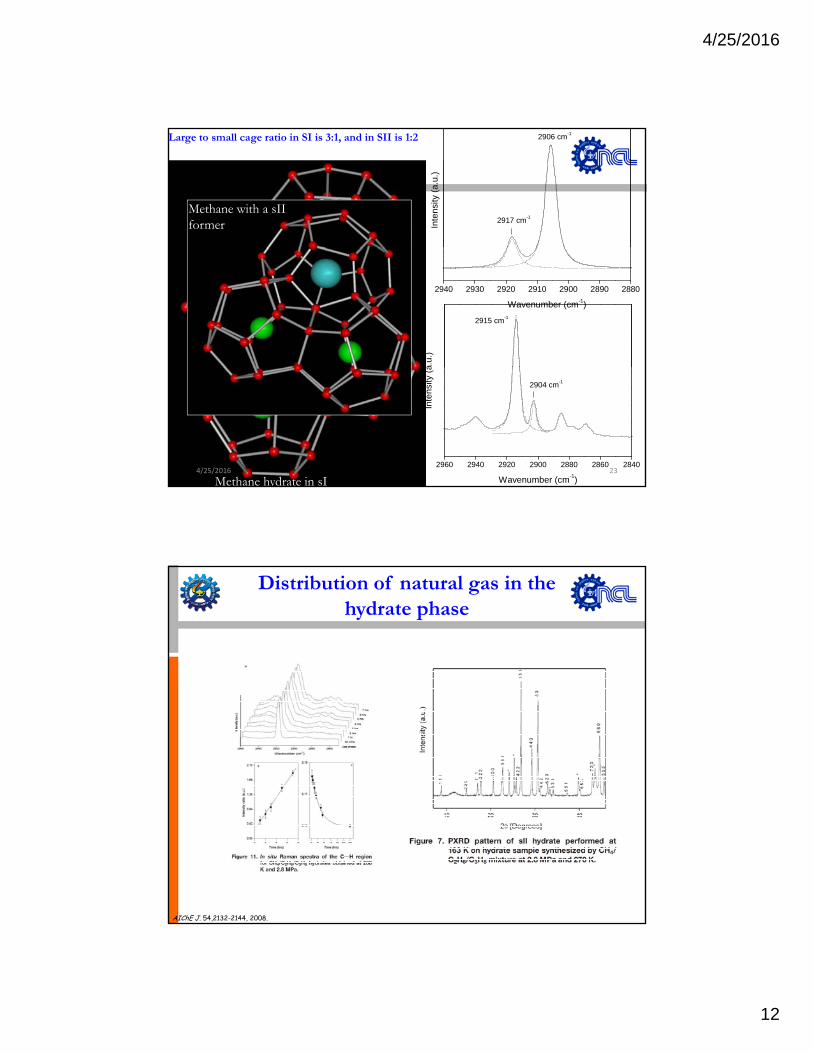
2917 cm-1
2906 cm-1
Inte
nsity
(a.u
.)
Large to small cage ratio in SI is 3:1, and in SII is 1:2
Methane with a sIIformer
2940 2930 2920 2910 2900 2890 2880
Wavenumber (cm-1)
2915 cm-1
a.u.
)
Methane hydrate in sI2960 2940 2920 2900 2880 2860 2840
Inte
nsity
(a
Wavenumber (cm-1)
2904 cm-1
4/25/2016 23
Distribution of natural gas in the hydrate phase
AIChE J. 54,2132-2144, 2008.
4/25/2016
13
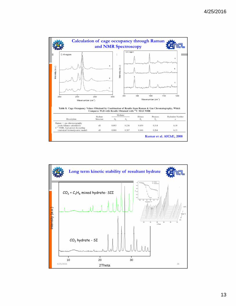
Calculation of cage occupancy through Raman and NMR Spectroscopy
Kumar et al. AIChE, 2008
CO2 + C3H8 mixed hydrate- SII
Long term kinetic stability of resultant hydrate
Inte
nsity
(a.u
.)
10 20 30
2Theta
CO2 hydrate - SI
4/25/2016 26
4/25/2016
14
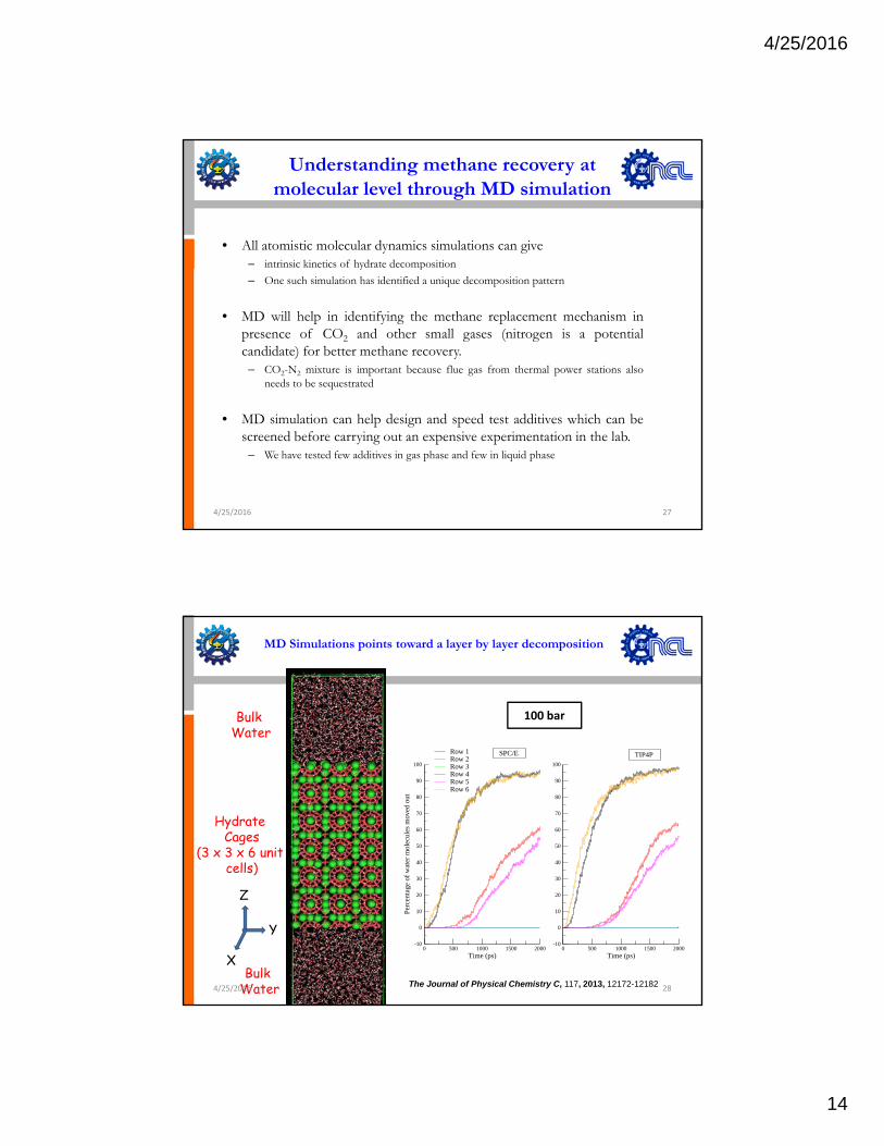
Understanding methane recovery at molecular level through MD simulation
• All atomistic molecular dynamics simulations can give– intrinsic kinetics of hydrate decompositiony p– One such simulation has identified a unique decomposition pattern
• MD will help in identifying the methane replacement mechanism inpresence of CO2 and other small gases (nitrogen is a potentialcandidate) for better methane recovery.
– CO2-N2 mixture is important because flue gas from thermal power stations alsoneeds to be sequestrated
• MD simulation can help design and speed test additives which can bescreened before carrying out an expensive experimentation in the lab.
– We have tested few additives in gas phase and few in liquid phase
4/25/2016 27
MD Simulations points toward a layer by layer decomposition
Bulk Water
100 bar
Hydrate Cages
(3 x 3 x 6 unit cells)
30
40
50
60
70
80
90
100
of
wat
er m
olec
ules
mov
ed o
ut
Row 1Row 2Row 3Row 4Row 5Row 6
30
40
50
60
70
80
90
100
SPC/E TIP4P
Z
Y
XBulk
Water
0 500 1000 1500 2000Time (ps)
-10
0
10
20
30
Perc
enta
ge o
f
0 500 1000 1500 2000Time (ps)
-10
0
10
20
30
The Journal of Physical Chemistry C, 117, 2013, 12172-121824/25/2016 28
4/25/2016
15
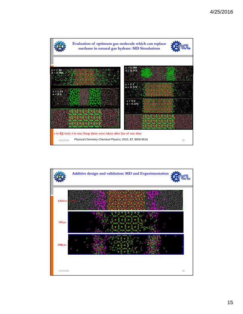
Evaluation of optimum gas molecule which can replace methane in natural gas hydrate: MD Simulations
ε = 0.085σ = 0.373ε = 1.23
σ = 0.353
ε = 2.3σ = 0.373
ε = 4.0σ = 0.373
.
ε = 1.23 σ = 0.6
ε in KJ/mol; σ in nm; Snap shots were taken after 2ns of run time
Physical Chemistry Chemical Physics, 2015, 17, 9509-95184/25/2016 29
Additive design and validation: MD and Experimentation
Additive + water
500 ps
4/25/2016 30
2000 ps
4/25/2016
16
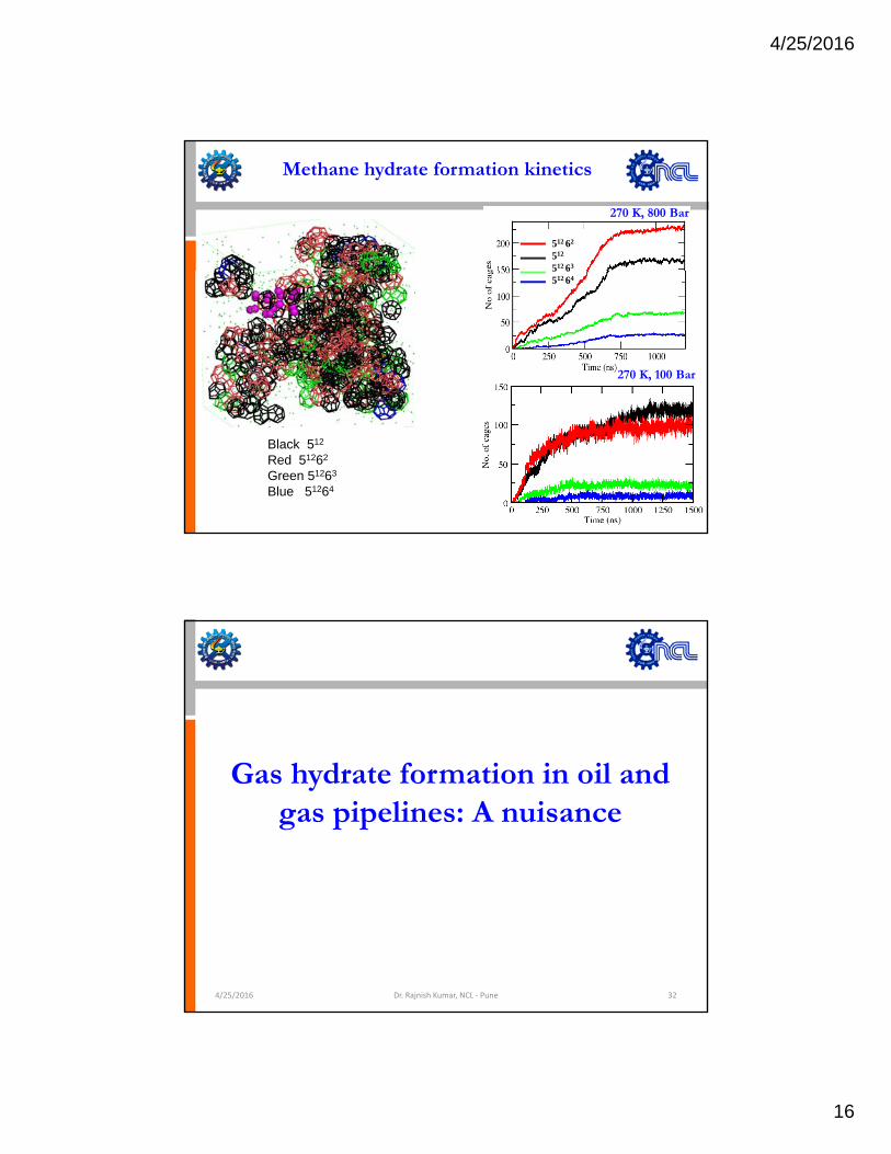
Methane hydrate formation kinetics
512 62
512
512 63
270 K, 800 Bar
5 6512 64
270 K, 100 Bar
Black 512
Red 51262
Green 51263
Blue 51264
Gas hydrate formation in oil and gas pipelines: A nuisance
4/25/2016 Dr. Rajnish Kumar, NCL ‐ Pune 32
4/25/2016
17
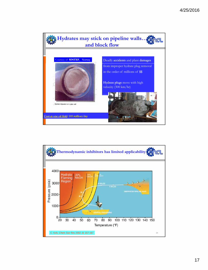
Courtesy of SINTEFSINTEF, Norway, Norway
Hydrates may stick on pipeline walls…and block flow
Deadly accidentsaccidents and plant damagesdamages
from improper hydrate plug removal
in the order of millions of $$$$
Hydrate plugsHydrate plugs move with high velocity (300 km/hr)
33
Cost at one oil fieldCost at one oil field: $10 million/day10 million/day
Thermodynamic inhibitors has limited applicability
34C. Koh, Chem Soc Rev 2002 31 157-167
4/25/2016
18
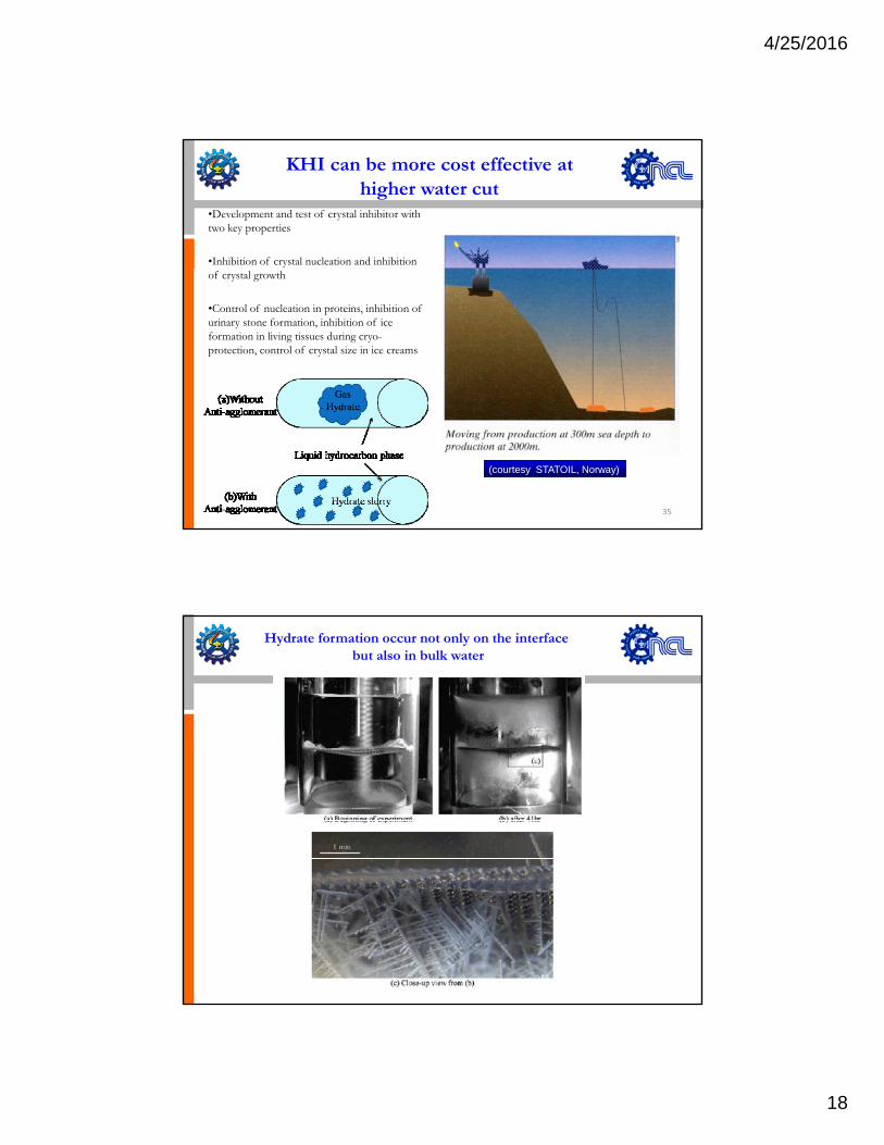
KHI can be more cost effective at higher water cut
•Development and test of crystal inhibitor with two key properties
•Inhibition of crystal nucleation and inhibition of crystal growth
•Control of nucleation in proteins, inhibition of urinary stone formation, inhibition of ice formation in living tissues during cryo-protection, control of crystal size in ice creams
35
(courtesy STATOIL, Norway)
Hydrate formation occur not only on the interface but also in bulk water
4/25/2016
19
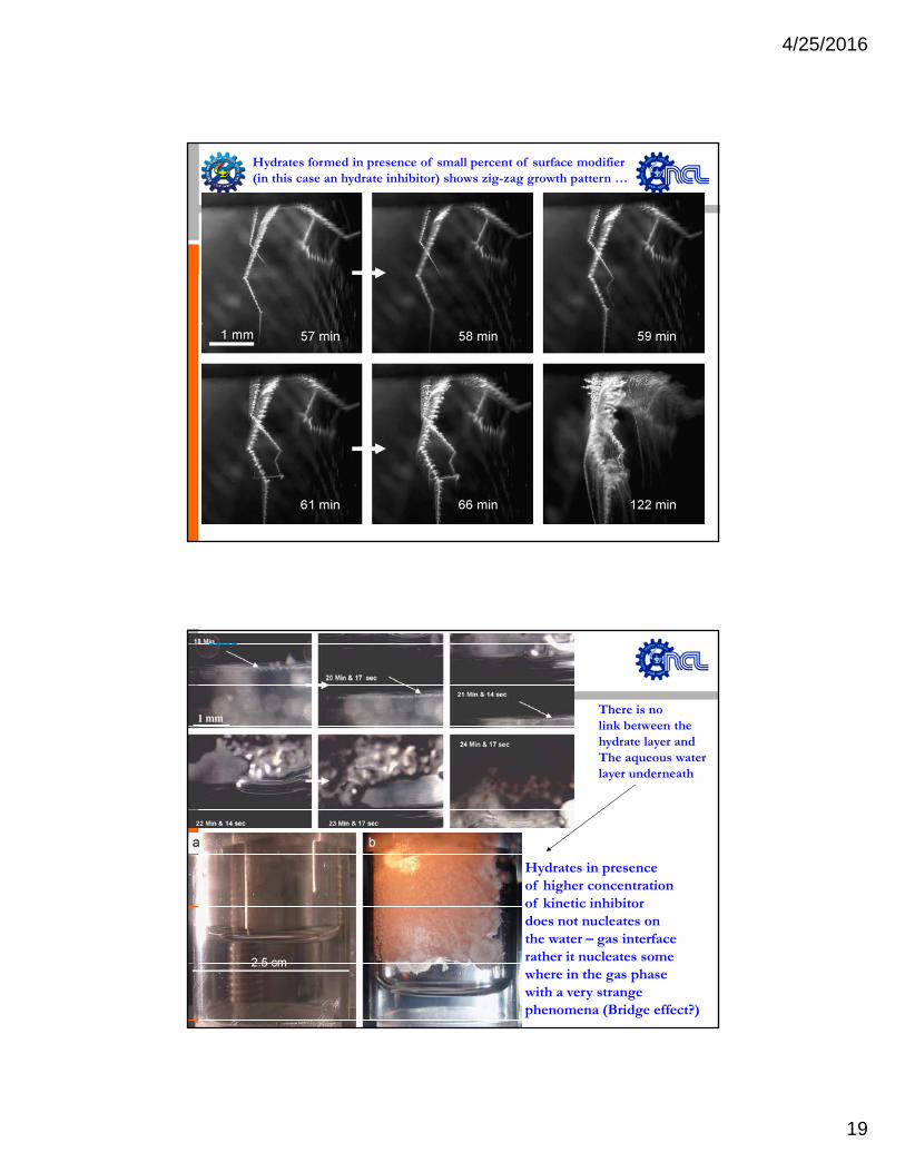
Hydrates formed in presence of small percent of surface modifier (in this case an hydrate inhibitor) shows zig-zag growth pattern …
There is nolink between the hydrate layer and The aqueous water
Hydrates in presenceof higher concentration
qlayer underneath
of kinetic inhibitordoes not nucleates on the water – gas interface rather it nucleates some where in the gas phase with a very strange phenomena (Bridge effect?)
4/25/2016
20
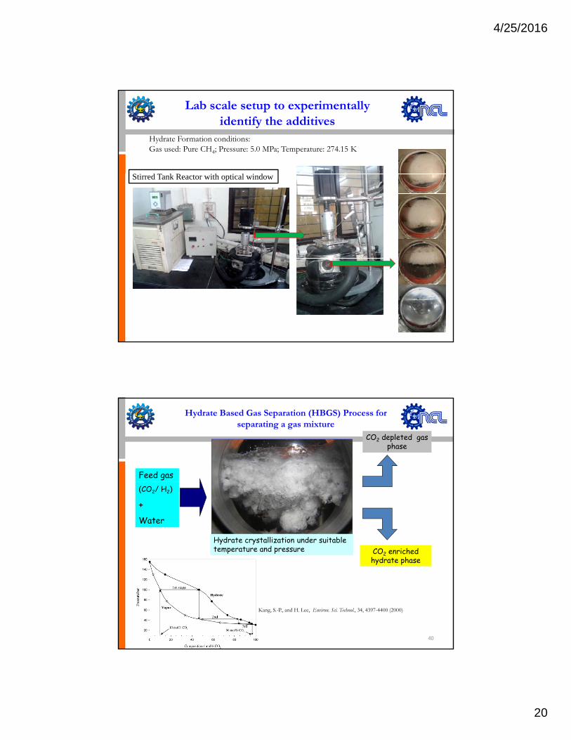
S i d T k R i h i l i d
Hydrate Formation conditions: Gas used: Pure CH4; Pressure: 5.0 MPa; Temperature: 274.15 K
Lab scale setup to experimentally identify the additives
Stirred Tank Reactor with optical window
Hydrate Based Gas Separation (HBGS) Process for separating a gas mixture
Feed gas
CO2 depleted gas phase
(CO2/ H2)
+Water
Hydrate crystallization under suitable temperature and pressure CO2 enriched
hydrate phase
40
Kang, S.-P., and H. Lee, Environ. Sci. Technol., 34, 4397-4400 (2000)
4/25/2016
21
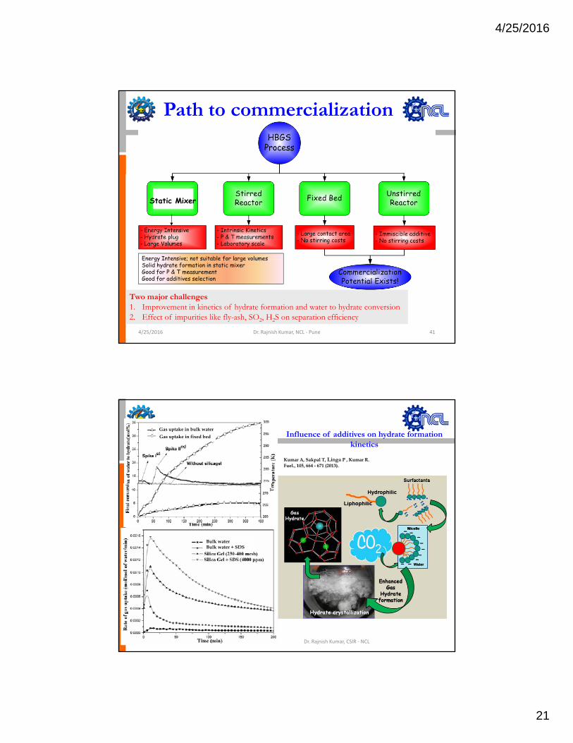
Path to commercialization
Static Mixer
Energy Intensive; not suitable for large volumesEnergy Intensive; not suitable for large volumesSolid hydrate formation in static mixerGood for P & T measurement Good for additives selection
4/25/2016 Dr. Rajnish Kumar, NCL ‐ Pune 41
Two major challenges1. Improvement in kinetics of hydrate formation and water to hydrate conversion2. Effect of impurities like fly-ash, SO2, H2S on separation efficiency
Influence of additives on hydrate formation kinetics
42
Gas uptake in bulk waterGas uptake in fixed bed
Kumar A, Sakpal T, Linga P , Kumar R. Fuel., 105, 664 - 671 (2013).
Bulk waterBulk water + SDS
4/25/2016 Dr. Rajnish Kumar, CSIR ‐ NCL
4/25/2016
22
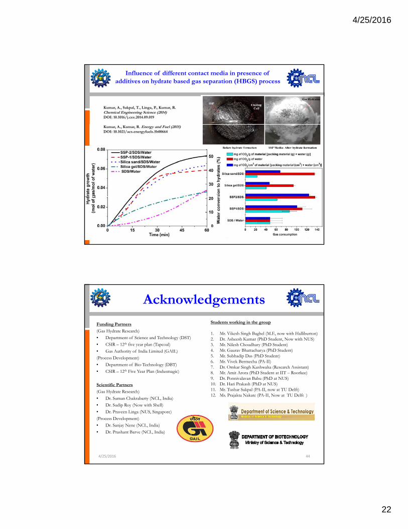
Influence of different contact media in presence of additives on hydrate based gas separation (HBGS) process
Kumar, A., Sakpal, T., Linga, P., Kumar, R. Chemical Engineering Science (2014)DOI: 10.1016/j.ces.2014.09.019
Kumar, A., Kumar, R. Energy and Fuel (2015) DOI: 10.1021/acs.energyfuels.5b00664
4/25/2016 Dr. Rajnish Kumar, CSIR ‐ NCL 43
Acknowledgements
Funding Partners
(Gas Hydrate Research)• Department of Science and Technology (DST)• CSIR 12th five year plan (Tapcoal)
Students working in the group
1. Mr. Vikesh Singh Baghel (M.E, now with Halliburton)2. Dr. Asheesh Kumar (PhD Student, Now with NUS)3 Mr Nil sh Ch dh r (PhD St d nt)• CSIR – 12th five year plan (Tapcoal)
• Gas Authority of India Limited (GAIL)(Process Development)• Department of Bio-Technology (DBT)• CSIR – 12th Five Year Plan (Indusmagic)
Scientific Partners
(Gas Hydrate Research)• Dr. Suman Chakrabarty (NCL, India)• D S di R (N ith Sh ll)
3. Mr. Nilesh Choudhary (PhD Student)4. Mr. Gaurav Bhattacharya (PhD Student)5. Mr. Subhadip Das (PhD Student)6. Mr. Vivek Bermecha (PA-II)7. Dr. Omkar Singh Kushwaha (Research Assistant)8. Mr. Amit Arora (PhD Student at IIT – Roorkee)9. Dr. Ponnivalavan Babu (PhD at NUS)10. Dr. Hari Prakash (PhD at NUS)11. Mr. Tushar Sakpal (PA-II, now at TU Delft)12. Ms. Prajakta Nakate (PA-II, Now at TU Delft )
• Dr. Sudip Roy (Now with Shell)• Dr. Praveen Linga (NUS, Singapore)(Process Development)• Dr. Sanjay Nene (NCL, India)• Dr. Prashant Barve (NCL, India)
4/25/2016 44
4/25/2016
23
Thank you !http://academic.ncl.res.in/k.rajnish
4/25/2016 45