Embed Size (px)
Citation preview
44 NASTT-NE NORTHEAST JOURNAL OF TRENCHLESS TECHNOLOGY PRACTICES FALL 2018 | WWW.NASTT-NE.ORG
UNDERSTANDING GEOLOGICAL HISTORY WHEN SELECTING TRENCHLESS INSTALLATION METHODSPART 2: EFFECTS OF GLACIAL AND PRE-GLACIAL COASTAL DRAINAGES ON HDD CROSSINGS
By: Bradford A Miller, P.G., Haley & Aldrich Dennis J Doherty, P.E., F. ASCE, Haley & Aldrich
INTRODUCTION
On many large, engineered trenchless installations, it is
imperative for the engineer to understand the geological history
of the subsurface, and determine the possible consequences and
controlling effects the geology has on the proposed crossing.
Deciphering the underlying geologic history (and its local
anomalies) drives selection of the most appropriate trenchless
method.
Part 2 of this three-part series looks closely at the complications
associated with an HDD crossing in an over-deepened, coastal
New England pre-glacial bedrock valley, and how it was affected
both by glacial advance and catastrophic meltwater releases
from an upstream glacial lake that filled the valley with large
cobbles and boulders, at thicknesses approaching 100 feet. A
more favorable 15-foot thick layer of sands and gravel below the
cobble/boulder layer was targeted for part of the HDD crossing
to install the 12-inch natural gas pipeline. This paper will review
the regional bedrock and local glacial geology, and its effect on the
engineering complications encountered during HDD drilling and
pipe installation.
SELECTION OF TRENCHLESS METHODS
When undertaking new trenchless installation work, it is
crucial that engineers and contractors understand how the ground
may behave in response to a given trenchless method. Much of
the expected behavior is based on real-world experience and also
a fundamental understanding of ground response when a specific
soil matrix is removed from the ground, whether the ground has
sufficient strength to support equipment and also to provide a
stable borehole to prevent inadvertent drill f luid returns (aka,
“frac-out”). Ground behavior from the Tunnel-Man’s Ground
Classification Guide like “raveling” (slow and fast), “squeezing,”
and “running” (or similar terms) are used to describe the
anticipated unstable ground and emphasize areas of concern.
The major concerns for trenchless projects are: weak
For more information, contact:Dennis J. Doherty, PE, F.ASCENational Practice Leader, Trenchless [email protected]
Novel approaches for a better result.That’s the Haley & Aldrich way.
There is more to trenchless engineering than drawing a line on a map. Haley & Aldrich brings industry-leading geotechnical and trenchless engineering expertise to the design process to minimize risk and deliver the greatest value.
haleyaldrich.com
NASTT-NE NORTHEAST JOURNAL OF TRENCHLESS TECHNOLOGY PRACTICES FALL 2018 | WWW.NASTT-NE.ORG 45
overburden soils, weight-of-hammer (WOH) material, nested
cobbles, gravel with little fines, running ground, and squeezing or
swelling ground all that suggest unfavorable ground conditions.
Where bedrock is shallow, the contrast in drilling behavior
between overburden (soil) and bedrock drilling is a further
complicating factor to consider.
For expensive and large-dollar trenchless projects, extensive
ground characterization is typically performed, but for small-
dollar trenchless projects, adequate ground characterization is
often overlooked, either due to lack of budget, a perception of
low value for the upfront project cost, or in the case of limited
engineering/designer experience with trenchless installations, a
misjudgment of the possible risks.
For many owners, a new installation project is just a line on
a piece of paper - but there is much more to it than that. It is
understanding construction risk and how to manage that risk and
how the ground will behave based on a specific trenchless method.
Thus, understanding the sequence of geologic events of a specific
area provides clues that can inform the designer of the anticipated
ground behavior.
TAUNTON RIVER CROSSING
This crossing in southeastern Massachusetts is an excellent
example of how geological history can affect both the planning,
execution and success of a trenchless project. A deep, pre-glacial
bedrock valley exhibiting different bedrock types on either side of
the river, combined with thick cobble and boulder gravels from a
rapid draining of an upstream glacial lake, required modifications
to the HDD crossing by the contractor due to the difficult ground
conditions.
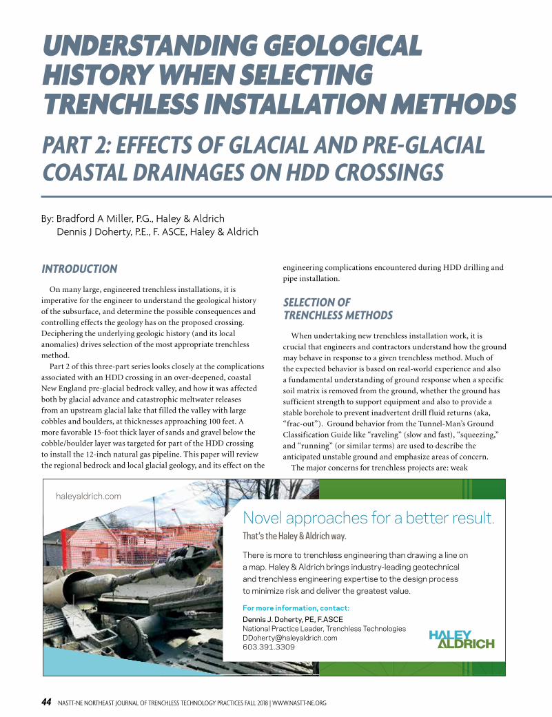
Figure 1 – Plan of 12-inch gas pipeline installed in 2016/2017 by HDD below the Taunton River. Base image from Google Earth Pro, dated 26 Feb 2018.
IT’S THE BEDROCK
Geologic maps (Reference 1) and subsurface data from highway bridge
studies (2) indicated the Taunton River is aligned with a major
northeast-trending bedrock fault zone separating Pennsylvanian-
age Rhode Island Formation rocks to the west from the older Fall
River Granites to the east. Yet, even though bedrock is exposed on
both sides of the Taunton River upstream, bridge borings indicate
the bedrock surface drops to at least 200-foot depths below the
river in the vicinity of the HDD crossing, and further deepens
to over 450 feet in depth below the Sakonnet River downstream,
between Portsmouth and Tiverton, RI.
Both the bedrock surface and fault between these two rock
types remain poorly understood. The Taunton River valley was
scoured by glacial ice advance, but recent research suggests (3) that
wholescale removal of all pre-glacial material down to rock by ice
was not as complete as often portrayed, a concept attributed to the
“thin ice” model near the terminal limit.
IT’S THE GLACIERS
Late Wisconsinan glacial ice reached its limit along the Rhode
Island and Massachusetts southern coasts around 28,000 to
23,700 years before present (YBP)(4) creating an intermittent string
of morainal islands along the ice terminus: Long Island, Block
Island, the Elizabeth Islands, and portions of Martha’s Vineyard
and Nantucket (5) (see Figure 2).
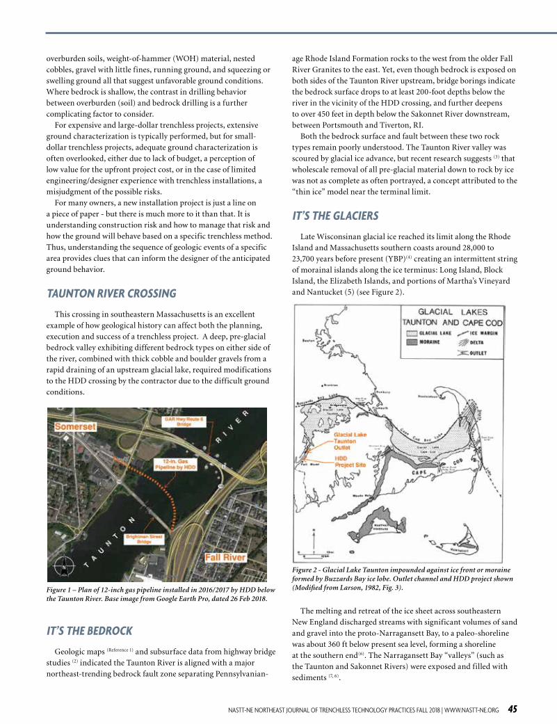
Figure 2 - Glacial Lake Taunton impounded against ice front or moraine formed by Buzzards Bay ice lobe. Outlet channel and HDD project shown (Modified from Larson, 1982, Fig. 3).
The melting and retreat of the ice sheet across southeastern
New England discharged streams with significant volumes of sand
and gravel into the proto-Narragansett Bay, to a paleo-shoreline
was about 360 ft below present sea level, forming a shoreline
at the southern end(6). The Narragansett Bay “valleys” (such as
the Taunton and Sakonnet Rivers) were exposed and filled with
sediments (7, 6).
46 NASTT-NE NORTHEAST JOURNAL OF TRENCHLESS TECHNOLOGY PRACTICES FALL 2018 | WWW.NASTT-NE.ORG
Deglaciation was rapid during warming trends, and
intermittent cold events caused ice retreat to halt and locally
re-advance, building moraine ridges during the cold periods (4, 8).
This retreat pattern is seen in several irregular topographic “belts”
of sandy moraine till, formed at the ice lobe margins, that cross
parts of southeastern Massachusetts (8), including the Sandwich
Moraine near Wareham. An impoundment termed “Glacial Lake
Taunton” was formed in a lowland against the ice margin on the
north and blocked by a debris dam across the Taunton River to
the southwest (9, 8). The shallow water body spread over much of
southeastern Massachusetts, exacerbated by crustal depression
due to weight of overlying ice (3).
At its maximum extent, Glacial Lake Taunton was estimated
to cover an area of approximately 54 square miles (5), extending
roughly from Norton, MA (to the west) to Kingston, MA (to the
east), and beyond Bridgewater to the north (10), and estimated to
be over 130 feet deep in places (11) with an overall lifespan slightly
longer than 300 years (12). The lake plane surface was about 55 to
65 ft above mean sea level (5).
Eventually, the contribution of glacial meltwater and sediments
caused the lake to overflow its basin and catastrophically breach,
erode, and drain down the outlet channel near Fall River, f lowing
into the upper reaches of Narragansett Bay (11). Engineering
investigations in the Fall River area provide us with direct
subsurface evidence of the Glacial Lake Taunton catastrophic
event.
EFFECTS OF MELTWATER RUNOFF FROM RETREATING GLACIERS
The draining of Glacial Lake Taunton rapidly discharged several
square miles of meltwater, entrained with sediment, down the
Taunton River rock valley leading into Narragansett Bay. The
high-velocity glacial meltwater carried very coarse debris of gravel,
cobbles and boulders in torrents, filling in the upper portions
of the rock valleys and deposited them on finer-grained sands
beneath. As depicted in Figure 3, the very coarse deposits are
primarily found on the Fall River side of the Taunton River and
approach 100 feet in thickness.
Figure 3 – Conceptual subsurface profile from test borings taken near the Taunton River HDD crossing. Profile is oriented west to east, with view towards north. Explanation of color representations are provided in text.
Geotechnical data assembled from the nearby Grand Army of
the Republic (GAR) Highway-Veterans Memorial Bridge (Route
6) bridge, from borings for the old Brightman Street Bridge, and
other proprietary sources indicated varying thicknesses of cobbles
and boulders, granular outwash sands, and deeper glaciolacustrine
deposits filled the Taunton River valley. The variation in
thicknesses can be attributed to variable warming periods during
the retreat of the glaciers in combination with rising land and rising
sea level when glacial run off was slower or f low impeded by the
rising ocean.
The presence of these coarse boulder-cobble-gravel deposits were
confirmed during the construction of the GAR Highway-Route
6 bridge by the Massachusetts Department of Transportation
between 2007 and 2011 (see Figure 1). The bridge was designed
to be founded on deep caisson (shaft) foundations. Difficult
drilling conditions in the cobble and boulder-containing glacial
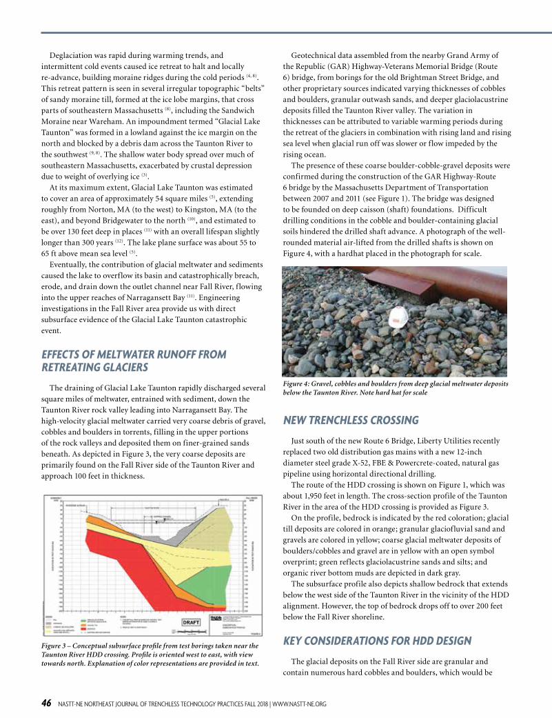
soils hindered the drilled shaft advance. A photograph of the well-
rounded material air-lifted from the drilled shafts is shown on
Figure 4, with a hardhat placed in the photograph for scale.
Figure 4: Gravel, cobbles and boulders from deep glacial meltwater deposits below the Taunton River. Note hard hat for scale
NEW TRENCHLESS CROSSING
Just south of the new Route 6 Bridge, Liberty Utilities recently
replaced two old distribution gas mains with a new 12-inch
diameter steel grade X-52, FBE & Powercrete-coated, natural gas
pipeline using horizontal directional drilling.
The route of the HDD crossing is shown on Figure 1, which was
about 1,950 feet in length. The cross-section profile of the Taunton
River in the area of the HDD crossing is provided as Figure 3.
On the profile, bedrock is indicated by the red coloration; glacial
till deposits are colored in orange; granular glaciofluvial sand and
gravels are colored in yellow; coarse glacial meltwater deposits of
boulders/cobbles and gravel are in yellow with an open symbol
overprint; green reflects glaciolacustrine sands and silts; and
organic river bottom muds are depicted in dark gray.
The subsurface profile also depicts shallow bedrock that extends
below the west side of the Taunton River in the vicinity of the HDD
alignment. However, the top of bedrock drops off to over 200 feet
below the Fall River shoreline.
KEY CONSIDERATIONS FOR HDD DESIGN
The glacial deposits on the Fall River side are granular and
contain numerous hard cobbles and boulders, which would be
NASTT-NE NORTHEAST JOURNAL OF TRENCHLESS TECHNOLOGY PRACTICES FALL 2018 | WWW.NASTT-NE.ORG 47
a critical factor to consider in the HDD drill-path design. In
contrast, the Somerset, MA (western side) of the alignment is
underlain by glacial till deposits overlying shallow bedrock, which
is classified as gray/black, fine-grained weathered shale of variable
strengths and fracture density. Glacial till typically contains
cobbles and boulders; nevertheless, the western side poses a slight
advantage for HDD because glacial till and “soft” bedrock tends to
remain open during pilot boring advance.
In contrast, highly granular deposits without silts or clays as
binding agents are subject to HDD drill f luid loss and unstable
behaviors (collapsing/raveling/enlarging of the borehole), as drill
f luids used in stabilizing the HDD drill hole may penetrate and
disperse into the permeable deposits if the f luid pressures are not
carefully controlled. High fluid pressures exiting the bore and
hydraulically fracturing the overlying soils may lead to inadvertent
drill f luid returns. As such, during the HDD drilling, drill f luids
were subject to seep out through the deposits into the Taunton
River itself on the Fall River side of the crossing.
With this faulted and highly variable bedrock geometry, a
challenging “mixed-face” condition for the HDD drill in this
situation could also be anticipated, where the drill advances
from bedrock-into-soil, or from soil-into-bedrock. Drills of this
nature have been successfully built, but the variation in ground
conditions must be carefully defined, clearly communicated, and
understood by the HDD contractor.
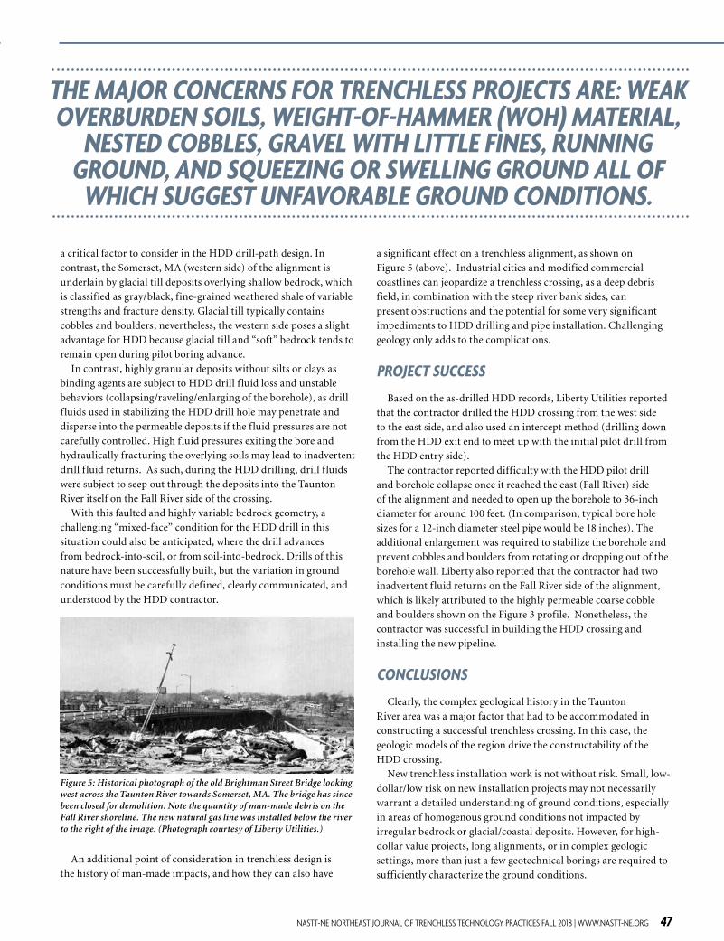
Figure 5: Historical photograph of the old Brightman Street Bridge looking west across the Taunton River towards Somerset, MA. The bridge has since been closed for demolition. Note the quantity of man-made debris on the Fall River shoreline. The new natural gas line was installed below the river to the right of the image. (Photograph courtesy of Liberty Utilities.)
An additional point of consideration in trenchless design is
the history of man-made impacts, and how they can also have
a significant effect on a trenchless alignment, as shown on
Figure 5 (above). Industrial cities and modified commercial
coastlines can jeopardize a trenchless crossing, as a deep debris
field, in combination with the steep river bank sides, can
present obstructions and the potential for some very significant
impediments to HDD drilling and pipe installation. Challenging
geology only adds to the complications.
PROJECT SUCCESS
Based on the as-drilled HDD records, Liberty Utilities reported
that the contractor drilled the HDD crossing from the west side
to the east side, and also used an intercept method (drilling down
from the HDD exit end to meet up with the initial pilot drill from
the HDD entry side).
The contractor reported difficulty with the HDD pilot drill
and borehole collapse once it reached the east (Fall River) side
of the alignment and needed to open up the borehole to 36-inch
diameter for around 100 feet. (In comparison, typical bore hole
sizes for a 12-inch diameter steel pipe would be 18 inches). The
additional enlargement was required to stabilize the borehole and
prevent cobbles and boulders from rotating or dropping out of the
borehole wall. Liberty also reported that the contractor had two
inadvertent f luid returns on the Fall River side of the alignment,
which is likely attributed to the highly permeable coarse cobble
and boulders shown on the Figure 3 profile. Nonetheless, the
contractor was successful in building the HDD crossing and
installing the new pipeline.
CONCLUSIONS
Clearly, the complex geological history in the Taunton
River area was a major factor that had to be accommodated in
constructing a successful trenchless crossing. In this case, the
geologic models of the region drive the constructability of the
HDD crossing.
New trenchless installation work is not without risk. Small, low-
dollar/low risk on new installation projects may not necessarily
warrant a detailed understanding of ground conditions, especially
in areas of homogenous ground conditions not impacted by
irregular bedrock or glacial/coastal deposits. However, for high-
dollar value projects, long alignments, or in complex geologic
settings, more than just a few geotechnical borings are required to
sufficiently characterize the ground conditions.
THE MAJOR CONCERNS FOR TRENCHLESS PROJECTS ARE: WEAK OVERBURDEN SOILS, WEIGHT-OF-HAMMER (WOH) MATERIAL,
NESTED COBBLES, GRAVEL WITH LITTLE FINES, RUNNING GROUND, AND SQUEEZING OR SWELLING GROUND ALL OF
WHICH SUGGEST UNFAVORABLE GROUND CONDITIONS.

48 NASTT-NE NORTHEAST JOURNAL OF TRENCHLESS TECHNOLOGY PRACTICES FALL 2018 | WWW.NASTT-NE.ORG
Northeast GSA, March 2015, Talk S2-6 powerpoint. (4) Ridge, John C. (2004). The Quaternary glaciation of western
New England with correlations to surrounding areas,
p. 169-199, in Developments in Quaternary Sciences,
Volume 2, Part B.
(5) Larson, G.J., 1982. Nonsynchronous Retreat of Ice Lobes
From Southeastern Massachusetts, p. 101-114, in Larson, G.J.,
and Stone, B.D. (eds.), Late Wisconsinan glaciation of New
England: Dubuque, Iowa, Kendall/Hunt.
(6) Boothroyd, J. (2010). Understanding Coastal Geologic
Hazards, Sea Level Rise and Climate Change in RI, Geology
Coastal Hazards presentation, 2nd National Workshop on
Subaqueous Soils, August 9, 2010 powerpoint. (7) Rosen, Peter; FitzGerald, Duncan; Buynevich, Ilya (2009).
Balancing Natural Processes and Competing Uses on a
Transgressive Barrier, Duxbury Beach, Massachusetts. In GSA
Special Paper 460, page 24.
(8) Stone, B.D., and Peper, J.D., 1982, Topographic Control of
Having a sound understanding of the local geologic history
provides a valuable understanding of how the ground may behave
when pipe jacking, microtunneling, or selecting between a small-
bore HDD versus large bore HDD. It is not just a line on a piece of
paper - understanding ground behavior when selecting a trenchless
method typically leads to lower risk with an associated decrease in
cost of that risk.
REFERENCES: (1) Hartshorn, J.H. (1967) Geology of the Taunton quadrangle,
Bristol and Plymouth Counties, Massachusetts. USGS Survey
Bulletin 1163-D. (2) Upson, J.E., and Spencer, C.W. (1964). Bedrock Valleys of the
New England Coast as Related to Fluctuations of Sea Level.
Geological Survey Professional Paper 454-M. P. 1-48
(3) Oakley, B.A., and Boothroyd, J.C. (2015). Volume of Sediment
Deposited in Glacial Lake Narragansett During Late
Wisconsinan Deglaciation: Implications on Sediment Source?
AA/EOE/M/W/Vet/Disabilitywww.michelscareers.us
UP FOR THE CHALLENGE?
Swift action & attitude are GAME CHANGERS.
www.michels.us/Trenchless
Transportation & Utility Contractor
Your story is told through the things we build.
SERVICES PERFORMEDMichels is an industry-leading utility and infrastructure contractor offering Mainline and Gas Distribution Pipeline Construction, Horizontal Directional Drilling, Electrical Transmission, Substation and Distribution Construction, Pipe Rehab, Direct Pipe, Fiber Optic Networks, Heavy Civil Work, Deep Foundations, Tunneling, Dewatering, Paving, Crushing, Road Building and Bridges.
FOR HIGH-DOLLAR VALUE PROJECTS, LONG ALIGNMENTS, OR IN COMPLEX GEOLOGIC SETTINGS, MORE THAN
JUST A FEW GEOTECHNICAL BORINGS ARE REQUIRED TO SUFFICIENTLY CHARACTERIZE THE GROUND CONDITIONS.
NASTT-NE NORTHEAST JOURNAL OF TRENCHLESS TECHNOLOGY PRACTICES FALL 2018 | WWW.NASTT-NE.ORG 49
the Deglaciation of Eastern Massachusetts: Ice Lobation and
Marine Incursion, p. 150-170, in Larson, G.J., and Stone, B.D.
(eds.), Late Wisconsinan glaciation of New England: Dubuque,
Iowa, Kendall/Hunt.(9) Hartshorn, J.H. (1960). Geology of the Bridgewater quadrangle,
Massachusetts. USGS Geologic Quadrangle Map GQ-127. (10) Chute, N.E. (1950). Surficial Geology of the Brockton
quadrangle, Massachusetts. USGS Geologic Quadrangle Map
GQ-6.
(11) FitzGerald, D.M. (2013). Origin and Stability of Tidal Inlets in
Massachusetts (Chapter 1, p. 13); in Formation and Evolution of
Multiple Tidal Inlets, Volume 44, Coastal and Estuarine Studies,
editors Aubrey, D.G. and Giese, G.S. published by AGU.
(12) Oakley and Boothroyd, (2013). Constrained Age of Glacial
Lake Narragansett and the Deglacial Chronology of the
Laurentide Ice Sheet in southeastern New England. Journal of
Paleolimnology, October 2013, Volume 50, Issue 3, p. 305-317. (13) Donnelly, J.P., Driscoll, N.W., Uchupi, E., Keigwin, L.D.,
Schwab, W.C., Thieler, E.R., and Swift, S.A. (2005).
Catastrophic Meltwater Discharge Down the Hudson Valley: A
Potential Trigger for the Intra-Allerod Cold Period. Geology 33,
p. 89–92. (14) Stone, B.D., Stone, J.R., DiGiacomo-Cohen, M.L., and Kincare,
K.A. (2012). Surficial geologic map of the Norton-Manomet-
Westport-Sconticut Neck 23-Quadrangle area in Southeastern
Massachusetts. USGS Open File Report OF2006-1260-I, Scale
1:24,000.
ABOUT THE AUTHORS:Bradford A Miller is Senior Geologist at
Haley & Aldrich, whose expertise is the
geologic interpretation of complex soil, rock
and groundwater conditions as they influence
a broad variety of geotechnical projects,
including trenchless utility construction,
pipelines, linear energy corridors, highway
rock slopes and foundation construction. He
has served as President of the New England Chapter of the
Association of Engineering and Environmental Geologists (AEG).
Dennis J Doherty is a Senior Consultant and
the National Practice Leader for Trenchless
Technologies at Haley & Aldrich, applying a
total trenchless approach on
microtunneling, HDD and other trenchless
method projects for private sector energy
clients. An ardent proponent of the benefits
and value of trenchless methods, Dennis has a
unique understanding of risk management as it relates to trenchless
design, having worked on a number of innovative projects across
the US. He serves on the NASTT No-Dig Show Program
Committee and is an instructor for NASTT’s HDD Good Practices
Course. Dennis is proud to be Past-Chair of the NASTT-NE
Chapter.
TECHNOLOGIES
®
LMKTECHNOLOGIES.COM | [email protected]
To learn more, call or visit us at:
INNOVATIVE CIPP SOLUTIONS
Insignia End Seal™ Vac-A-Tee™ T-Liner® Performance Liner® CIPMH Performance Liner®
Gasket Sealing Outside Cleanout Main-To-Lateral Lining Lateral Lining System Full Depth Sectional Spot Repair