Embed Size (px)
Citation preview
Understanding
the Approved
Document Sections C to P
V 1.0
Understanding the Approved Document
i
This handbook is electronically published by the Building and Construction Authority,
Singapore.
The Building and Construction Authority (“BCA”), its agents, employees and
subcontractors are not to be held liable for any claim or dispute arising out of or relating
to the information provided in this handbook. BCA reserves the right to update this
handbook periodically without prior notice.
The contents of this handbook are protected by copyright and other forms of proprietary
rights. All rights, title and interest in the contents are owned by, licensed to or controlled
by BCA and shall not be reproduced, republished, uploaded, posted, transmitted or
otherwise distributed in any way, without the prior written permission of BCA.
Modification of any of the contents or use of the contents for any other purpose will be a
violation of BCA’s copyright and other intellectual property rights.
Copyright © 2018 Building and Construction Authority
Understanding the Approved Document
ii
INTRODUCTION
Aim:
The aim of this handbook is to assist the reader in understanding the architectural
requirements from Clause C to P of the Approved Document Ver 7.0. This handbook is
expected to be useful to architects and designers who may need guidance about
compliance with the building regulations.
FEATURES
This book contains a number of features to aid understanding of the Approved Document:
Explanatory notes
Clauses in Approved Document consist of technical jargons which can be better understood using diagrams. Definitions of technical terms as well as diagrams and photographs are used to explain the clauses to aid understanding.
Site Observations
The information provided here pre-empts the industry on the possible and frequently seen non-compliances found on site.
Additional Clarifications
Additional Clarifications provide further explanations on the Clauses stated in Approved
Document as well as common queries raised by practitioners.
Understanding the Approved Document
iii
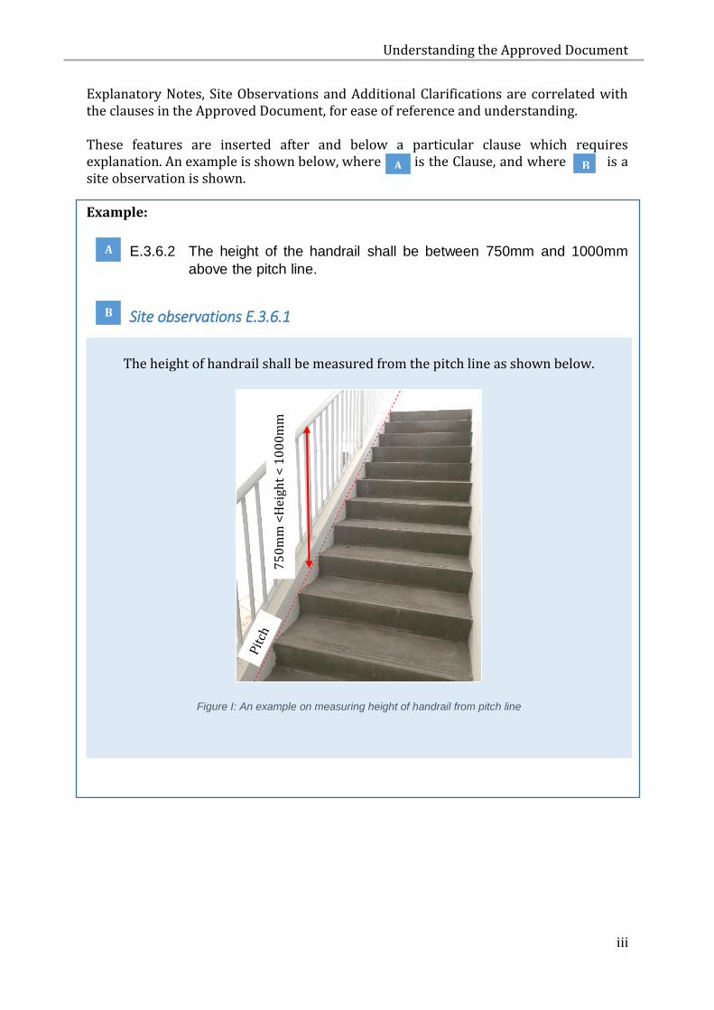
Explanatory Notes, Site Observations and Additional Clarifications are correlated with the clauses in the Approved Document, for ease of reference and understanding. These features are inserted after and below a particular clause which requires explanation. An example is shown below, where is the Clause, and where is a site observation is shown. Example:
E.3.6.2 The height of the handrail shall be between 750mm and 1000mm
above the pitch line.
Site observations E.3.6.1
The height of handrail shall be measured from the pitch line as shown below.
Figure I: An example on measuring height of handrail from pitch line
75
0m
m <
Hei
ght
< 1
00
0m
m
A
B
A B
Understanding the Approved Document
iv
TABLE OF CONTENTS
C HEADROOM AND CEILING HEIGHT ............................................................................. 1
C.1 OBJECTIVE ................................................................................................................ 1
C.2 PERFORMANCE REQUIREMENT ................................................................................. 1
C.3 ACCEPTABLE SOLUTION ............................................................................................. 4
C.3.2 HEADROOM .......................................................................................................... 4
C.3.3 CEILING HEIGHT ..................................................................................................... 8
D ACCESSIBILITY IN BUILT ENVIRONMENT .................................................................. 10
D.1 OBJECTIVE .............................................................................................................. 10
D.2 PERFORMANCE REQUIREMENT ............................................................................... 10
D.3 ACCEPTABLE SOLUTION ........................................................................................... 11
E STAIRCASES ............................................................................................................ 12
E.1 OBJECTIVE ............................................................................................................... 12
E.2 PERFORMANCE REQUIREMENT ................................................................................ 12
E.3 ACCEPTABLE SOLUTION ........................................................................................... 13
E.3.2 PROJECTION ........................................................................................................ 13
E.3.3 WIDTH OF STAIRCASE ......................................................................................... 13
E.3.4 RISERS AND TREADS ............................................................................................ 13
E.3.5 LANDING ............................................................................................................. 16
E.3.6 HANDRAILS ......................................................................................................... 20
F LIGHTING ................................................................................................................ 25
F.1 OBJECTIVE .............................................................................................................. 25
F.2 PERFORMANCE REQUIREMENT ............................................................................... 25
F.3 ACCEPTABLE SOLUTION ........................................................................................... 25
F.3.2 NATURAL LIGHTING ............................................................................................ 26
G VENTILATION .......................................................................................................... 27
G.1 OBJECTIVE ............................................................................................................... 27
G.2 PERFORMANCE REQUIREMENT ................................................................................ 27
G.3 ACCEPTABLE SOLUTION ........................................................................................... 28
G.3.2 NATURAL VENTILATION ................................................................................... 29
H SAFETY FROM FALLING ............................................................................................ 39
Understanding the Approved Document
v
H.1 OBJECTIVE ............................................................................................................... 39
H.2 PERFORMANCE REQUIREMENT ................................................................................ 39
H.3 ACCEPTABLE SOLUTION ........................................................................................... 42
H.3.2 HEIGHT OF BARRIER ........................................................................................ 42
H.3.3 HORIZONTAL LOADING AND DESIGN OF GLASS PANEL BARRIERS..................... 44
H.3.4 SIZE OF OPENING ............................................................................................. 44
H.3.5 GLASS BARRIER ................................................................................................ 56
I ENERGY EFFICIENCY ................................................................................................ 57
I.1 OBJECTIVE .............................................................................................................. 57
I.2 PERFORMANCE REQUIREMENT ............................................................................... 57
I.3 ACCEPTABLE SOLUTION ........................................................................................... 58
I.3.2 AIR-CONDITIONED BUILDING .................................................................................. 58
I.3.3 NON AIR-CONDITIONED BUILDING .......................................................................... 60
I.3.4 AIR TIGHTNESS AND LEAKAGE ................................................................................. 60
I.3.5 AIR-CONDITIONING SYSTEM.................................................................................... 61
I.3.6 ARTIFICIAL LIGHTING ............................................................................................... 61
I.3.7 SWITCHING CONTROL ............................................................................................. 61
I.3.8 ENERGY AUDITING .................................................................................................. 62
J ROOF ...................................................................................................................... 63
J.1 OBJECTIVE .............................................................................................................. 63
J.2 PERFORMANCE REQUIREMENT ............................................................................... 63
J.3 ACCEPTABLE SOLUTION ........................................................................................... 63
K LIFTS AND ESCALATORS ........................................................................................... 64
K.1 OBJECTIVE .............................................................................................................. 64
K.2 PERFORMANCE REQUIREMENT ............................................................................... 64
K.3 ACCEPTABLE SOLUTION ........................................................................................... 65
L LIGHTNING PROTECTION ......................................................................................... 70
L.1 OBJECTIVE .............................................................................................................. 70
L.2 PERFORMANCE REQUIREMENT ............................................................................... 70
L.3 ACCEPTABLE SOLUTION ........................................................................................... 70
M SAFETY OF WINDOWS ............................................................................................. 74
M.1 OBJECTIVE .............................................................................................................. 74
Understanding the Approved Document
vi
M.2 PERFORMANCE REQUIREMENT ............................................................................... 74
M.3 ACCEPTABLE SOLUTION ........................................................................................... 74
N USE OF GLASS AT HEIGHT ........................................................................................ 77
N.1 OBJECTIVE .............................................................................................................. 77
N.2 PERFORMANCE REQUIREMENT ............................................................................... 77
N.3 ACCEPTABLE SOLUTION ........................................................................................... 77
O PROTECTION FROM INJURY BY VEHICLES IN BUILDINGS ........................................... 80
O.1 OBJECTIVE .............................................................................................................. 80
O.2 PERFORMANCE REQUIREMENT ............................................................................... 80
O.3 ACCEPTABLE SOLUTION ........................................................................................... 80
O.3.2 HORIZONTAL LOADING OF BARRIER ................................................................. 80
P DAYLIGHT REFLECTANCE ......................................................................................... 81
P.1 OBJECTIVE .............................................................................................................. 81
P.2 PERFORMANCE REQUIREMENT ............................................................................... 81
P.3 ACCEPTABLE SOLUTION ........................................................................................... 81
ANNEX 1 – LOFT REQUIREMENTS ...................................................................................... 85
ANNEX 2 – MECHANISED CAR PARKING SYSTEMS ............................................................... 89
ANNEX 3 – MOVABLE PANELS ......................................................................................... 92
Understanding the Approved Document
1
C HEADROOM AND CEILING HEIGHT
C.1 OBJECTIVE
C.1.1 The objectives of paragraph C.2.1 are–
(a) to protect people from injury caused by inadequate headroom; and
(b) injury or loss of amenity caused by inadequate height of room or
space.
C.2 PERFORMANCE REQUIREMENT
C.2.1 Any room or space in a building must be provided with –
(a) adequate headroom; and
(b) adequate ceiling height,
for the intended uses of the room or space.
C.2.2 The requirements in paragraph C.2.1(a) and (b) do not apply to any of
the following rooms or spaces:
(a) any attic that –
(i) does not exceed an area of 10 square metres; and
(ii) is in a house that is built for the owner’s own use;
(b) any equipment or plant room;
(c) the underside of any staircase or escalator if the staircase or escalator is not located along an access route or circulation space;
(d) any toilet, bathroom or lavatory in any house built for the owner’s own use;
(e) any store room not exceeding an area of 6 square metres.
Understanding the Approved Document
2
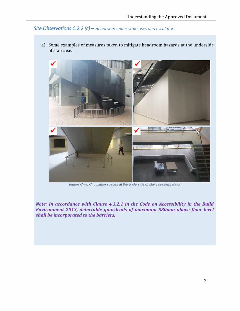
Site Observations C.2.2 (c) – Headroom under staircases and escalators
a) Some examples of measures taken to mitigate headroom hazards at the underside
of staircase.
Figure C—I: Circulation spaces at the underside of staircases/escalator
Note: In accordance with Clause 4.3.2.1 in the Code on Accessibility in the Build Environment 2013, detectable guardrails of maximum 580mm above floor level shall be incorporated to the barriers.

Understanding the Approved Document
3
b) In Figure C-II, the low headroom hazard near the entrance door is mitigated by enclosing the affected circulation area.
Figure C—II: Low headroom at entrance is mitigated by building up a storage area underneath the staircase
c) Headroom requirements are applicable where deficient of headroom affects the functional use of space and poses as an overhead hazard for users.
Figure C—III: Function of space at underside of staircase
Understanding the Approved Document
4
C.2.3 The requirement in paragraph C.2.1(a) does not apply to any of the
following rooms or spaces:
(a) any corridor or lobby;
(b) any toilet, bathroom, lavatory or powder room;
(c) any localised area within a room or space where there is a drop in ceiling height due to physical constraints such as structural beams or building services.
C.3 ACCEPTABLE SOLUTION
C.3.1 The requirement in paragraph C.2.1 is deemed to be satisfied if the
specifications set out in paragraphs C.3.2 and C.3.3 are complied with.
C.3.2 HEADROOM
C.3.2.1 The headroom of every room, access route and circulation space shall
not be less than 2.0 m.
Understanding the Approved Document
5
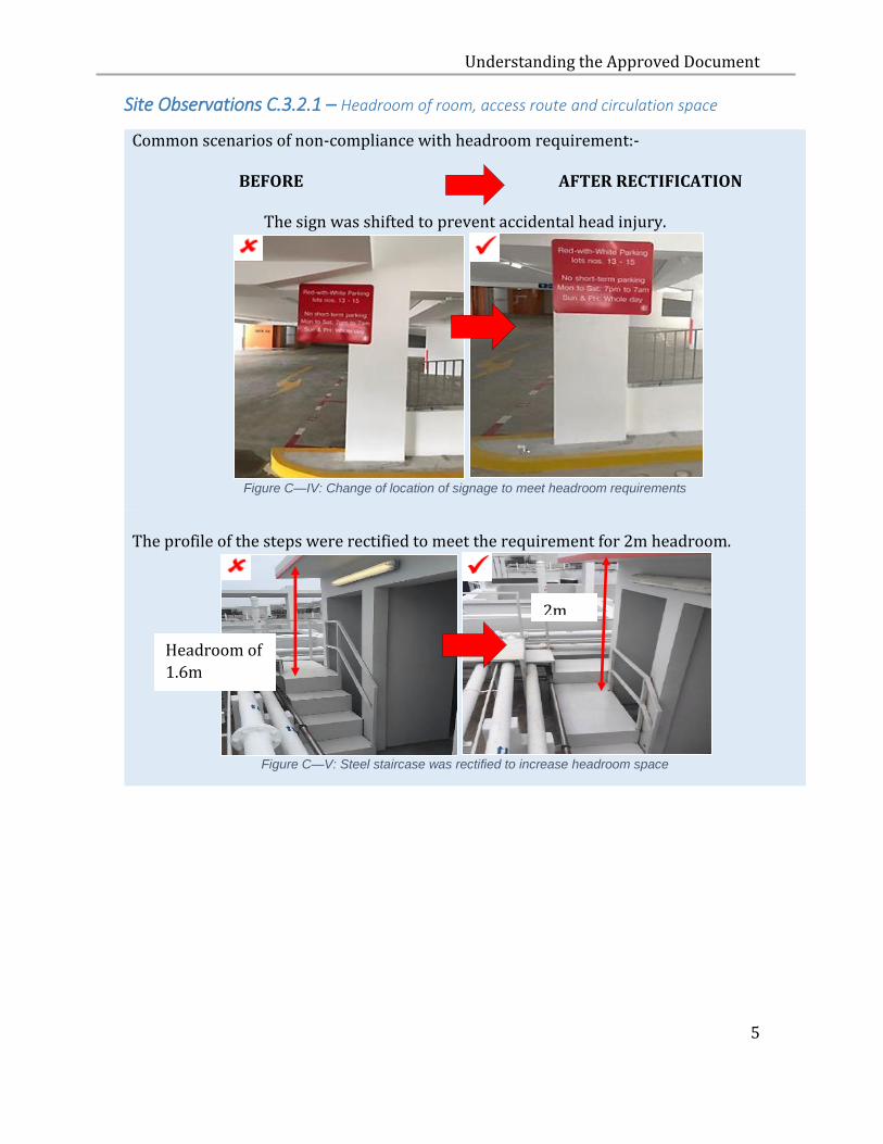
Site Observations C.3.2.1 – Headroom of room, access route and circulation space
Common scenarios of non-compliance with headroom requirement:- BEFORE AFTER RECTIFICATION
The sign was shifted to prevent accidental head injury.
Figure C—IV: Change of location of signage to meet headroom requirements
The profile of the steps were rectified to meet the requirement for 2m headroom.
Figure C—V: Steel staircase was rectified to increase headroom space
2m
Headroom of
1.6m
Understanding the Approved Document
6
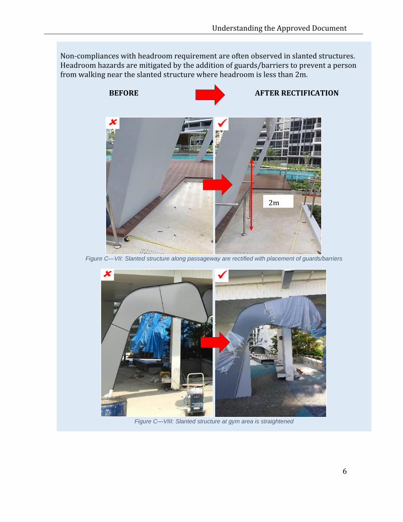
Non-compliances with headroom requirement are often observed in slanted structures. Headroom hazards are mitigated by the addition of guards/barriers to prevent a person from walking near the slanted structure where headroom is less than 2m. BEFORE AFTER RECTIFICATION
Figure C—VII: Slanted structure along passageway are rectified with placement of guards/barriers
Figure C—VIII: Slanted structure at gym area is straightened
2m
Understanding the Approved Document
7
C.3.2.2 For sheltered car parks, the headroom at parking lots and driveway shall
not be less than 2.2m.
Note: 1 The term “access route” shall include a covered walkway or
footway of a building.
2 The headroom is measured from the finished floor level to the underside of any beam, duct, service pipe, fixture, fitting or other obstruction or projection; and in the case of a doorway, it shall be measured up to the underside of the transom.
3 Windows, which open into any access route or circulation space, shall not result in any inadequacy in headroom in the access route or circulation space.
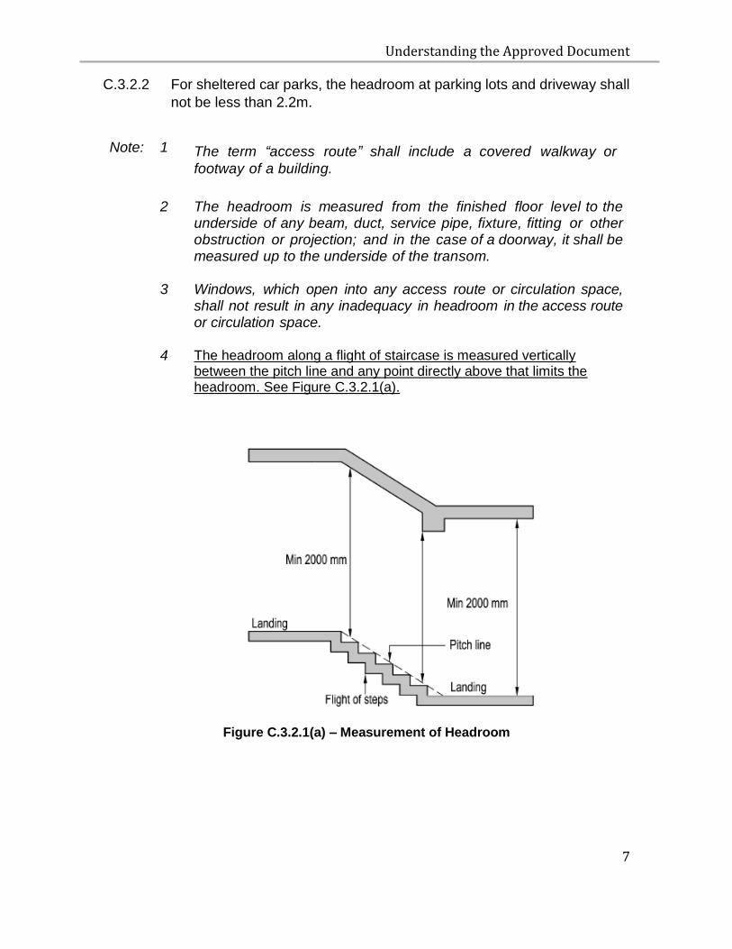
4 The headroom along a flight of staircase is measured vertically between the pitch line and any point directly above that limits the headroom. See Figure C.3.2.1(a).
Figure C.3.2.1(a) – Measurement of Headroom
Understanding the Approved Document
8
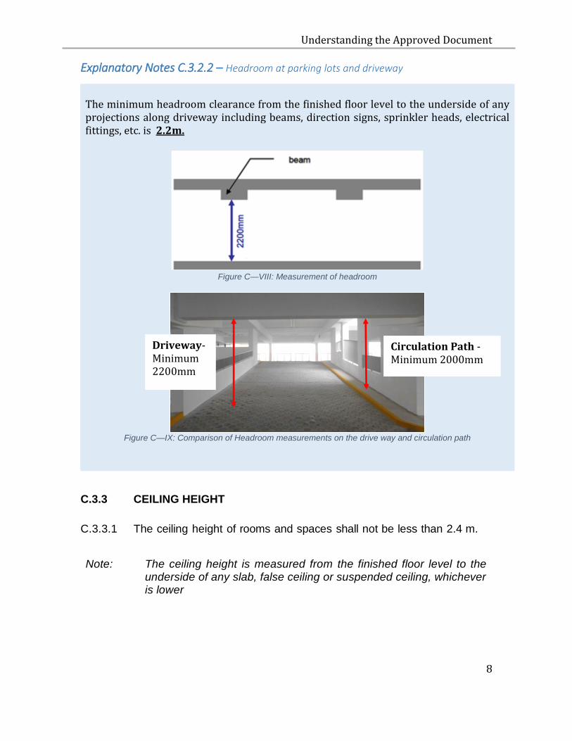
Explanatory Notes C.3.2.2 – Headroom at parking lots and driveway
The minimum headroom clearance from the finished floor level to the underside of any projections along driveway including beams, direction signs, sprinkler heads, electrical fittings, etc. is 2.2m.
Figure C—VIII: Measurement of headroom
Figure C—IX: Comparison of Headroom measurements on the drive way and circulation path
C.3.3 CEILING HEIGHT
C.3.3.1 The ceiling height of rooms and spaces shall not be less than 2.4 m.
Note: The ceiling height is measured from the finished floor level to the underside of any slab, false ceiling or suspended ceiling, whichever is lower
Circulation Path -Minimum 2000mm
Driveway- Minimum 2200mm
Understanding the Approved Document
9
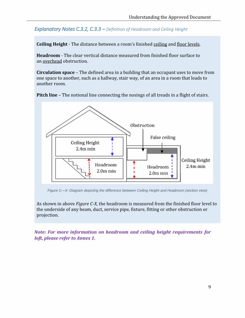
Explanatory Notes C.3.2, C.3.3 – Definition of Headroom and Ceiling Height
Ceiling Height - The distance between a room's finished ceiling and floor levels. Headroom - The clear vertical distance measured from finished floor surface to an overhead obstruction. Circulation space – The defined area in a building that an occupant uses to move from one space to another, such as a hallway, stair way, of an area in a room that leads to another room. Pitch line – The notional line connecting the nosings of all treads in a flight of stairs.
Figure C—X: Diagram depicting the difference between Ceiling Height and Headroom (section view)
As shown in above Figure C-X, the headroom is measured from the finished floor level to the underside of any beam, duct, service pipe, fixture, fitting or other obstruction or projection.
Note: For more information on headroom and ceiling height requirements for
loft, please refer to Annex 1.
Understanding the Approved Document
10
D ACCESSIBILITY IN BUILT ENVIRONMENT
D.1 OBJECTIVE
D.1.1 The objective of paragraphs D.2.1 to D.2.4 is to ensure that persons
with disabilities are able to easily gain access to and exit from the whole
or part of a building, and that persons with disabilities, children between
90cm and 120cm in height, caregivers of infants, and nursing women
are able to carry out their activities within the building with reasonable
ease.
D.2 PERFORMANCE REQUIREMENT
D.2.1 At least one access route shall have barrier-free features to enable
persons with disabilities to –
(a) approach the building or the vehicle park; and
(b) have access to those spaces where they may be expected to work
or visit.
D.2.2 Sanitary facilities that are appropriate for use by persons with
disabilities and sanitary facilities that are appropriate for use by children
between 90cm and 120cm in height shall be adequately provided for
use by such persons.
D.2.3 Appropriate facilities for lactation and changing of diapers shall be
adequately provided and be accessible for use by nursing women and
caregivers of infants.
D.2.4 Appropriate wayfinding guides such as signages or audible or tactile
information providing directions or instructions shall be adequately
provided within a building to guide persons with disabilities to spaces or
facilities where or which they may be expected to work, visit or use.
Understanding the Approved Document
11
D.3 ACCEPTABLE SOLUTION
D.3.1 The requirements in paragraphs D.2.1 to D.2.4 are deemed to be
satisfied if the provisions and facilities for persons with disabilities,
children between 90cm and 120cm in height, caregivers of infants, and
nursing women comply with the Code on Accessibility in the Built
Environment issued by the Commissioner of Building Control.
Understanding the Approved Document
12
E STAIRCASES
E.1 OBJECTIVE
E.1.1 The objective of paragraphs E.2.1and E.2.2 is to protect people from
injury and to facilitate access during movement from one level to
another in a building.
E.2 PERFORMANCE REQUIREMENT
E.2.1 A staircase (including a flight of 2 steps or more) shall provide a safe
and suitable passage for movement of people.
E.2.2 A staircase shall have –
(a) handrails or guides to assist movement;
(b) landings to break a fall and provide a place for rest;
(c) sufficient width, tread and riser to avoid injury;
(d) sufficient headroom to avoid injury; and
(e) barriers to prevent people from falling off the edge of any open
side that has a drop of 1,000 mm or more
E.2.3 The requirement in paragraph E.2.2(a) does not apply to a staircase
located in any of the following rooms or spaces:
(a) any equipment or plant room;
(b) any production area of an industrial building;
(c) any house built for the owner’s own use.
E.2.4 The requirements in paragraph E.2.2(b) and (c) do not apply to a
staircase located in any of the following rooms or spaces:
Understanding the Approved Document
13
(a) any equipment or plant room;
(b) any production area of an industrial building;
(c) any attic that –
(i) does not exceed an area of 10 square metres; and
(ii) is in a residential building;
(d) any house built for the owner’s own use.
E.3 ACCEPTABLE SOLUTION
E.3.1 The requirements in paragraphs E.2.1 and E.2.2 are deemed to be
satisfied if a staircase is designed and constructed in accordance with
the specifications set out in paragraphs E.3.2 to E.3.6.
E.3.2 PROJECTION
E.3.2.1 No projection, other than handrails, is allowed in a staircase within
a height of 2.0 m from the landing or pitch line.
E.3.3 WIDTH OF STAIRCASE
E.3.3.1 The clearance of the width of every staircase shall not be less than
900 mm.
Note:
The width is measured from the inner side of the wall, balustrade or handrail.
E.3.4 RISERS AND TREADS
E.3.4.1 The height of a riser shall not be more than 175 mm.
Understanding the Approved Document
14
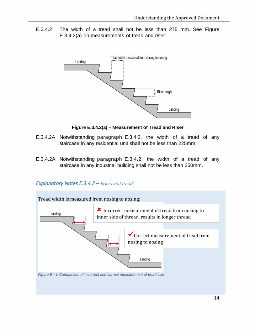
E.3.4.2 The width of a tread shall not be less than 275 mm. See Figure
E.3.4.2(a) on measurements of tread and riser.
Figure E.3.4.2(a) – Measurement of Tread and Riser
E.3.4.2A Notwithstanding paragraph E.3.4.2, the width of a tread of any
staircase in any residential unit shall not be less than 225mm.
E.3.4.2A Notwithstanding paragraph E.3.4.2, the width of a tread of any
staircase in any industrial building shall not be less than 250mm.
Explanatory Notes E.3.4.2 – Risers and treads
Tread width is measured from nosing to nosing:
Figure E—I: Comparison of incorrect and correct measurement of tread size
Incorrect measurement of tread from nosing to
inner side of thread, results in longer thread measurement.
Correct measurement of tread from
nosing to nosing
Understanding the Approved Document
15
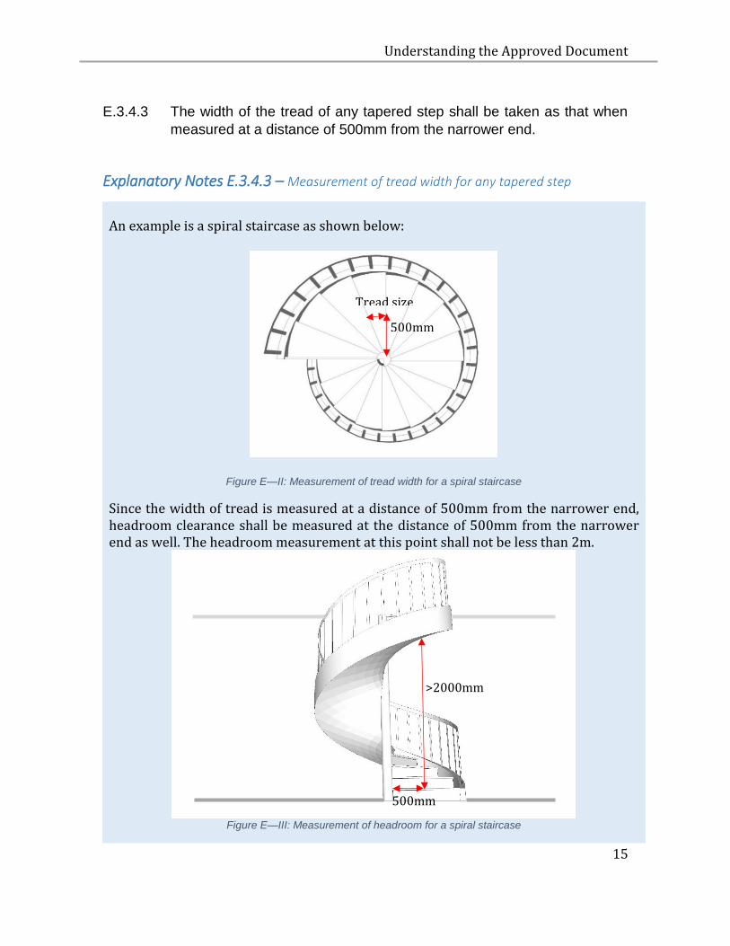
E.3.4.3 The width of the tread of any tapered step shall be taken as that when
measured at a distance of 500mm from the narrower end.
Explanatory Notes E.3.4.3 – Measurement of tread width for any tapered step
An example is a spiral staircase as shown below:
Figure E—II: Measurement of tread width for a spiral staircase
Since the width of tread is measured at a distance of 500mm from the narrower end, headroom clearance shall be measured at the distance of 500mm from the narrower end as well. The headroom measurement at this point shall not be less than 2m.
Figure E—III: Measurement of headroom for a spiral staircase
500mm
Tread size
>2000mm
500mm
Understanding the Approved Document
16
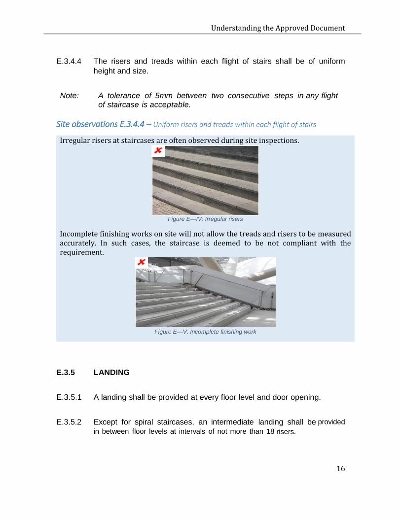
E.3.4.4 The risers and treads within each flight of stairs shall be of uniform
height and size.
Note: A tolerance of 5mm between two consecutive steps in any flight of staircase is acceptable.
Site observations E.3.4.4 – Uniform risers and treads within each flight of stairs
Irregular risers at staircases are often observed during site inspections.
Figure E—IV: Irregular risers
Incomplete finishing works on site will not allow the treads and risers to be measured accurately. In such cases, the staircase is deemed to be not compliant with the requirement.
Figure E—V: Incomplete finishing work
E.3.5 LANDING
E.3.5.1 A landing shall be provided at every floor level and door opening.
E.3.5.2 Except for spiral staircases, an intermediate landing shall be provided
in between floor levels at intervals of not more than 18 risers.
Understanding the Approved Document
17
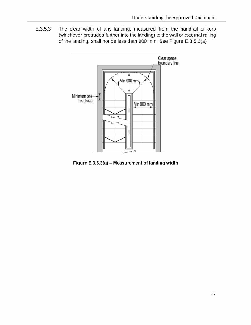
E.3.5.3 The clear width of any landing, measured from the handrail or kerb
(whichever protrudes further into the landing) to the wall or external railing
of the landing, shall not be less than 900 mm. See Figure E.3.5.3(a).
Figure E.3.5.3(a) – Measurement of landing width
Understanding the Approved Document
18
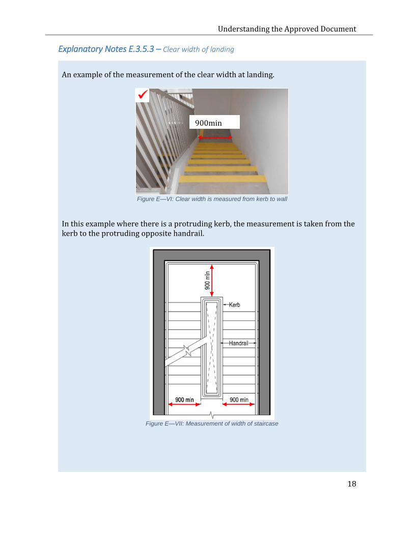
Explanatory Notes E.3.5.3 – Clear width of landing
An example of the measurement of the clear width at landing.
Figure E—VI: Clear width is measured from kerb to wall
In this example where there is a protruding kerb, the measurement is taken from the kerb to the protruding opposite handrail.
Figure E—VII: Measurement of width of staircase
900min
Understanding the Approved Document
19
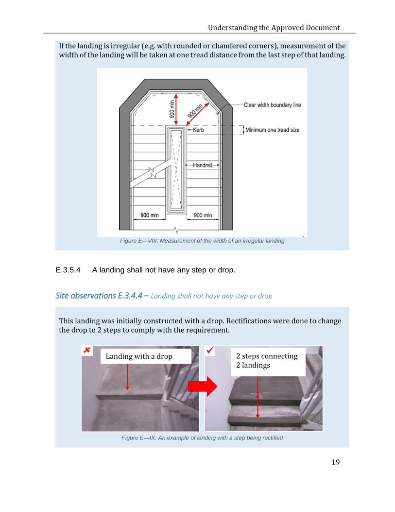
If the landing is irregular (e.g. with rounded or chamfered corners), measurement of the width of the landing will be taken at one tread distance from the last step of that landing.
Figure E—VIII: Measurement of the width of an irregular landing
E.3.5.4 A landing shall not have any step or drop.
Site observations E.3.4.4 – Landing shall not have any step or drop
This landing was initially constructed with a drop. Rectifications were done to change the drop to 2 steps to comply with the requirement.
Figure E—IX: An example of landing with a step being rectified
Landing with a drop
2 steps connecting 2 landings
Understanding the Approved Document
20
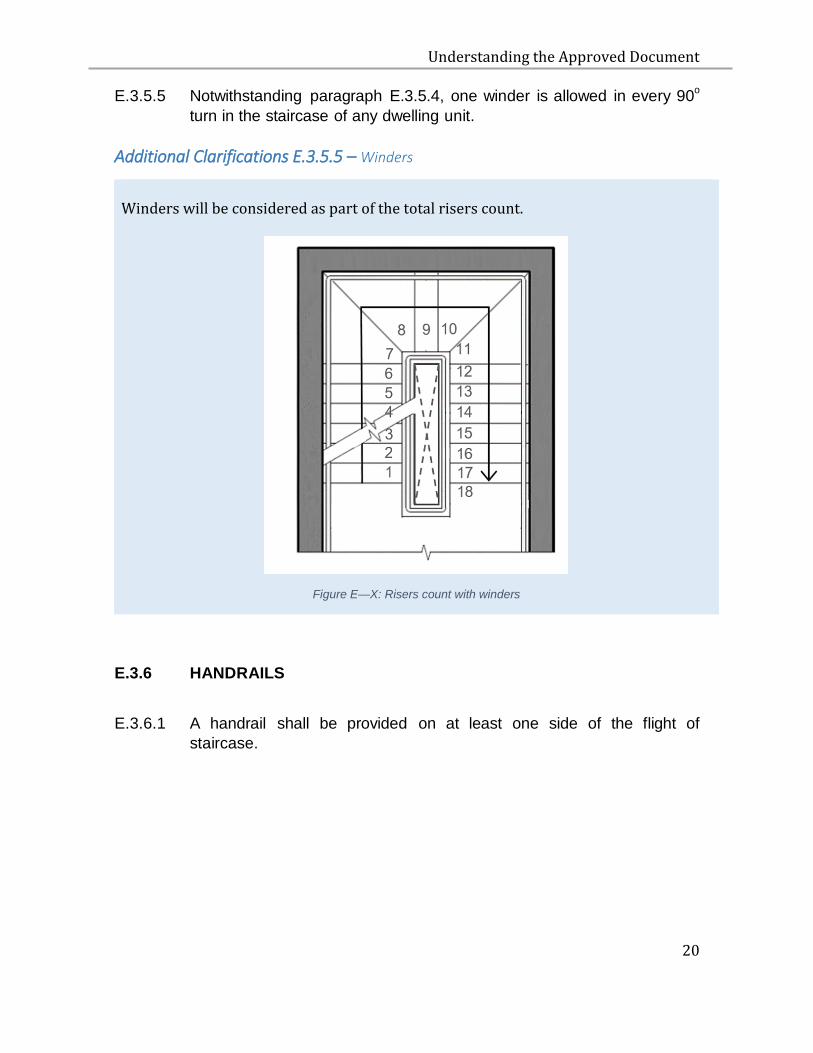
E.3.5.5 Notwithstanding paragraph E.3.5.4, one winder is allowed in every 90o
turn in the staircase of any dwelling unit.
Additional Clarifications E.3.5.5 – Winders
Winders will be considered as part of the total risers count.
Figure E—X: Risers count with winders
E.3.6 HANDRAILS
E.3.6.1 A handrail shall be provided on at least one side of the flight of
staircase.
Understanding the Approved Document
21
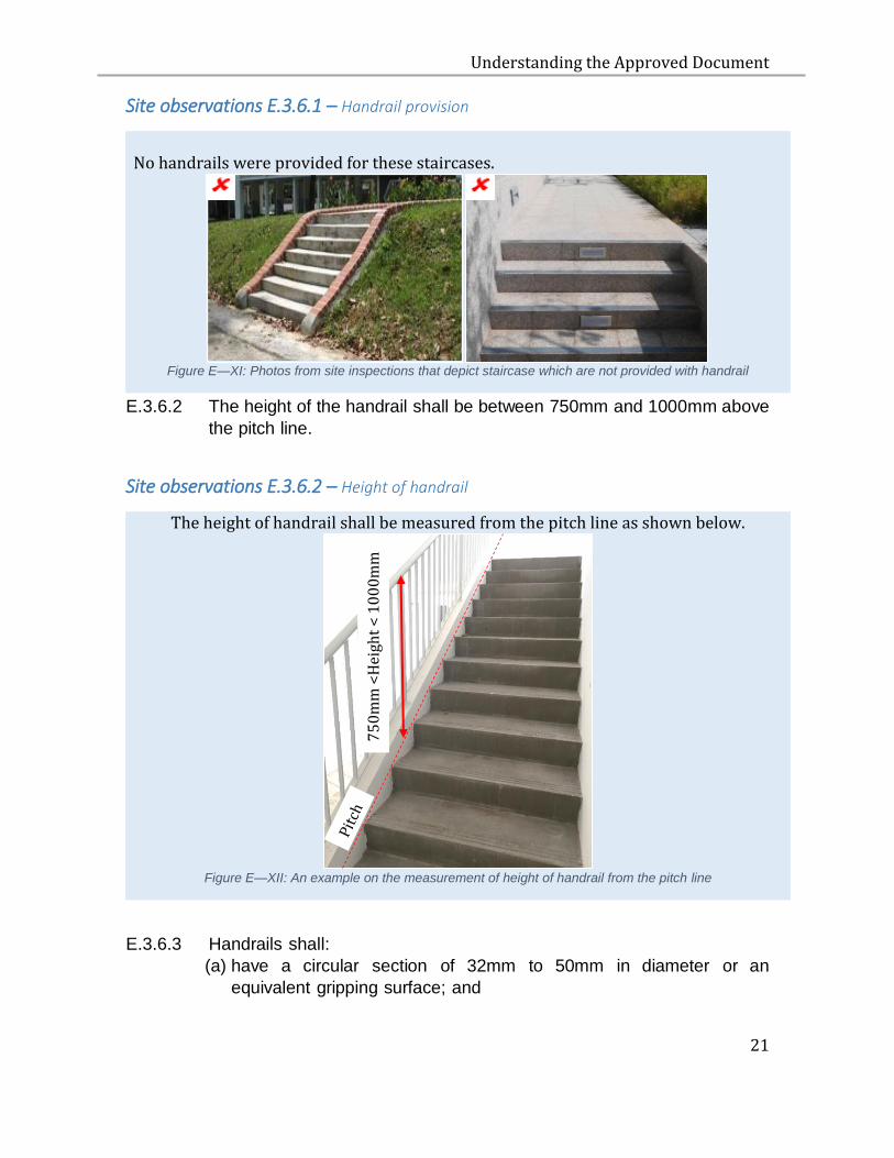
Site observations E.3.6.1 – Handrail provision
No handrails were provided for these staircases.
Figure E—XI: Photos from site inspections that depict staircase which are not provided with handrail
E.3.6.2 The height of the handrail shall be between 750mm and 1000mm above
the pitch line.
Site observations E.3.6.2 – Height of handrail
The height of handrail shall be measured from the pitch line as shown below.
Figure E—XII: An example on the measurement of height of handrail from the pitch line
E.3.6.3 Handrails shall:
(a) have a circular section of 32mm to 50mm in diameter or an
equivalent gripping surface; and
75
0m
m <
Hei
ght
< 1
00
0m
m
Understanding the Approved Document
22
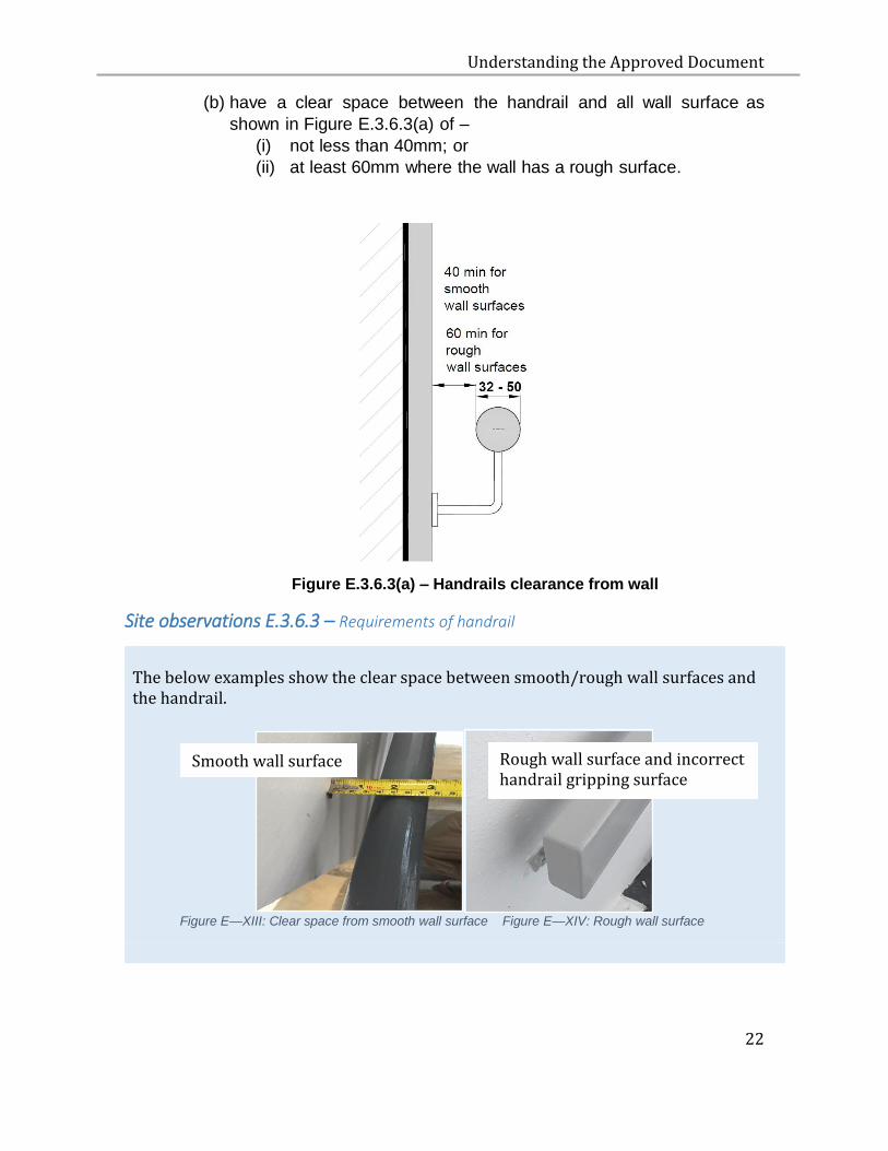
(b) have a clear space between the handrail and all wall surface as
shown in Figure E.3.6.3(a) of –
(i) not less than 40mm; or
(ii) at least 60mm where the wall has a rough surface.
Figure E.3.6.3(a) – Handrails clearance from wall
Site observations E.3.6.3 – Requirements of handrail
The below examples show the clear space between smooth/rough wall surfaces and the handrail.
Figure E—XIII: Clear space from smooth wall surface Figure E—XIV: Rough wall surface
Smooth wall surface
Rough wall surface and incorrect handrail gripping surface

Understanding the Approved Document
23
E.3.6.4 A recess containing a handrail shall extend at least 450mm above the
top of the rail as shown in Figure E.3.6.4(a).
Figure E.3.6.4(a) – Handrail in recess
Note: A handrail shall be continuous throughout the entire length of
stairs and the ends of the handrail should be properly formed or
rounded off so that they do not pose a danger to the user.
Understanding the Approved Document
24
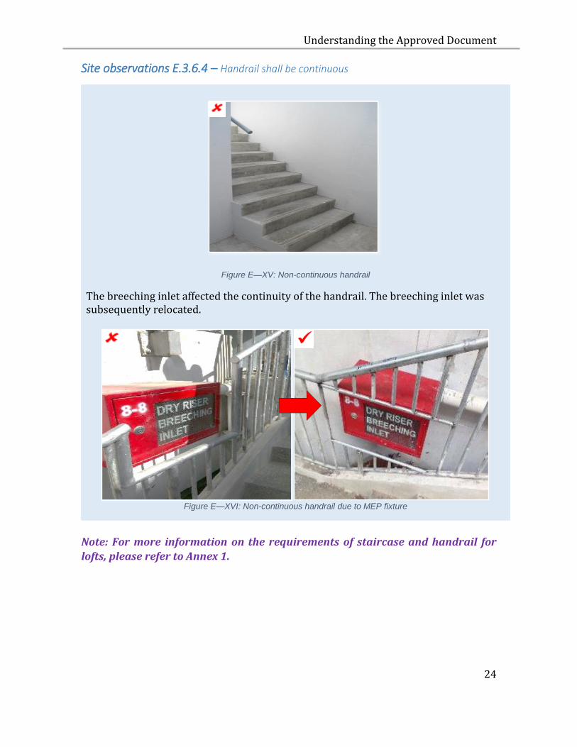
Site observations E.3.6.4 – Handrail shall be continuous
Figure E—XV: Non-continuous handrail
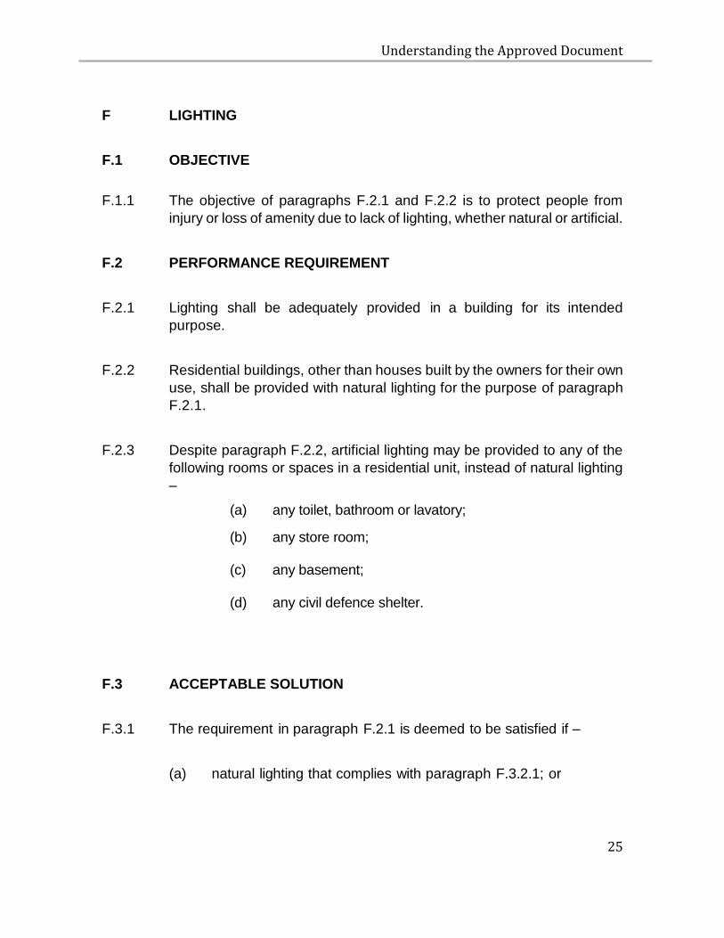
The breeching inlet affected the continuity of the handrail. The breeching inlet was subsequently relocated.
Figure E—XVI: Non-continuous handrail due to MEP fixture
Note: For more information on the requirements of staircase and handrail for
lofts, please refer to Annex 1.
Understanding the Approved Document
25
F LIGHTING
F.1 OBJECTIVE
F.1.1 The objective of paragraphs F.2.1 and F.2.2 is to protect people from
injury or loss of amenity due to lack of lighting, whether natural or artificial.
F.2 PERFORMANCE REQUIREMENT
F.2.1 Lighting shall be adequately provided in a building for its intended
purpose.
F.2.2 Residential buildings, other than houses built by the owners for their own
use, shall be provided with natural lighting for the purpose of paragraph
F.2.1.
F.2.3 Despite paragraph F.2.2, artificial lighting may be provided to any of the
following rooms or spaces in a residential unit, instead of natural lighting
–
(a) any toilet, bathroom or lavatory;
(b) any store room;
(c) any basement; (d) any civil defence shelter.
F.3 ACCEPTABLE SOLUTION
F.3.1 The requirement in paragraph F.2.1 is deemed to be satisfied if –
(a) natural lighting that complies with paragraph F.3.2.1; or
Understanding the Approved Document
26
(b) artificial lighting that complies with the recommended illuminance
given in SS 531 - Code of Practice for Lighting of Work Places is
provided.
F.3.2 NATURAL LIGHTING
F.3.2.1 Natural lighting shall be provided by means of one or more windows
or other openings with an aggregate light transmitting area of not less
than 10% of the floor area of the room or space required to be lighted.
Note: 1 The light transmitting area for a window and other similar devices may be measured over the framing members and glazing bars.
2 For the purpose of promoting energy efficiency in buildings, the use of artificial lighting as the sole means of lighting is to be discouraged.
Understanding the Approved Document
27
G VENTILATION
G.1 OBJECTIVE
G.1.1 The objective of paragraphs G.2.1 and G.2.2 is to protect people from
loss of amenity due to lack of fresh air.
G.2 PERFORMANCE REQUIREMENT
G.2.1 Ventilation shall be adequately provided in a building for its intended
occupancy.
G.2.2 Residential buildings, other than houses built by the owners for their
own use, shall be provided with natural ventilation for the purpose of
paragraph G.2.1.
G.2.3 The requirement in paragraph G.2.1 does not apply to any of the following
rooms or spaces –
(a) any store room not exceeding an area of 6 square metres;
(b) any private lift lobby not exceeding an area of 6 square metres.
G.2.4 Despite paragraph G.2.2, mechanical ventilation may be provided to any
of the following rooms or spaces in any residential development:
(i) any fitness room;
(ii) any clubhouse;
(iii) any civil defence shelter;
(iv) any toilet, bathroom or lavatory;
Understanding the Approved Document
28
G.3 ACCEPTABLE SOLUTION
G.3.1 The requirement in paragraph G.2.1 is deemed to be satisfied if –
(a) natural ventilation that complies with paragraphs G.3.2.1 and
G.3.2.2; or
(b) mechanical ventilation that complies with the ventilation rates
given in SS 553 - Code of Practice for Air-Conditioning and
Mechanical Ventilation in Buildings; or
Additional clarifications G.3.2.1(b) – Mechanical ventilation at car park
Should the car park or parts of the car park be mechanically ventilated, the ventilation rates of the mechanical ventilation system shall comply with SS553.
(c) air-conditioning system that complies with -
(for new erections of non-residential buildings)
(i) the ventilation rates given in SS553 – Code of Practice for
Air- Conditioning and Mechanical Ventilation in Buildings;
and
(ii) the Minimum Efficiency Reporting Value (MERV) for cleaning
the air given in SS553 – Code of Practice for Air-
Conditioning and Mechanical Ventilation in Buildings
(for all other types of buildings works)
The ventilation rates given in SS553 – Code of Practice for Air-
Conditioning and Mechanical Ventilation in Buildings.
is provided.
Understanding the Approved Document
29
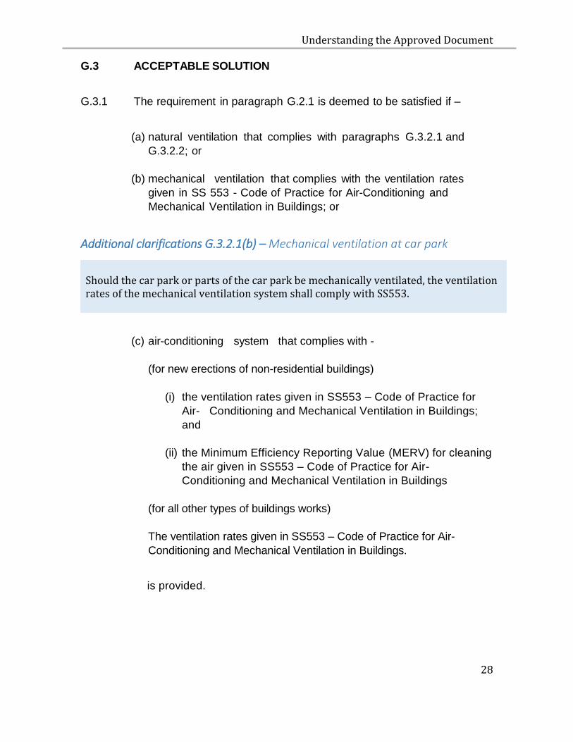
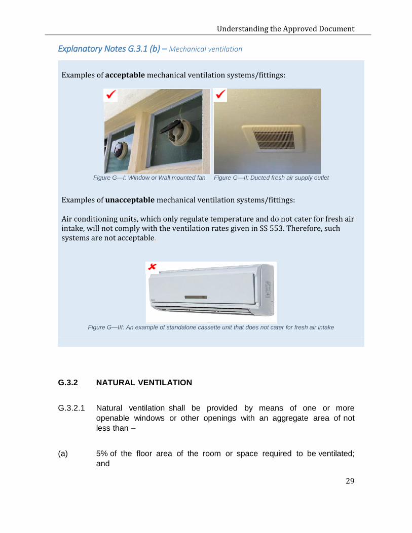
Explanatory Notes G.3.1 (b) – Mechanical ventilation
Examples of acceptable mechanical ventilation systems/fittings:
Figure G—I: Window or Wall mounted fan Figure G—II: Ducted fresh air supply outlet
Examples of unacceptable mechanical ventilation systems/fittings: Air conditioning units, which only regulate temperature and do not cater for fresh air intake, will not comply with the ventilation rates given in SS 553. Therefore, such systems are not acceptable.
Figure G—III: An example of standalone cassette unit that does not cater for fresh air intake
G.3.2 NATURAL VENTILATION
G.3.2.1 Natural ventilation shall be provided by means of one or more
openable windows or other openings with an aggregate area of not
less than –
(a) 5% of the floor area of the room or space required to be ventilated;
and
Understanding the Approved Document
30
(b) in the case of an aboveground car park, comply with relevant clause in
SS553 – Code of Practice for Air-Conditioning and Mechanical Ventilation
in Buildings.
Note: Except otherwise stated in the following, any openable window or opening may be considered to be unobstructed
(a) The effective open area of a sliding window is the unobstructed area when the sliding window is opened fully.
(b) The effective open area of any opening installed with fixed
louvers shall be assumed to be 50% of the area of the opening. (c) For any casement windows installed with restrictors and can
be opened at least 30 degrees or more, the effective open area of the window shall be assumed to be 50% of the window opening.
Understanding the Approved Document
31
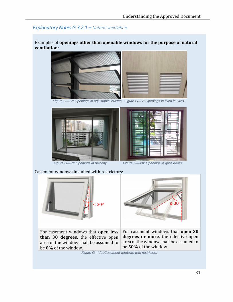
Explanatory Notes G.3.2.1 – Natural ventilation
Examples of openings other than openable windows for the purpose of natural ventilation:
Figure G—IV: Openings in adjustable louvres Figure G—V: Openings in fixed louvres
Figure G—VI: Openings in balcony Figure G—VII: Openings in grille doors
Casement windows installed with restrictors:
For casement windows that open less than 30 degrees, the effective open area of the window shall be assumed to be 0% of the window.
For casement windows that open 30 degrees or more, the effective open area of the window shall be assumed to be 50% of the window.
Figure G—VIII:Casement windows with restrictors
< 30o ≥ 30o
Understanding the Approved Document
32
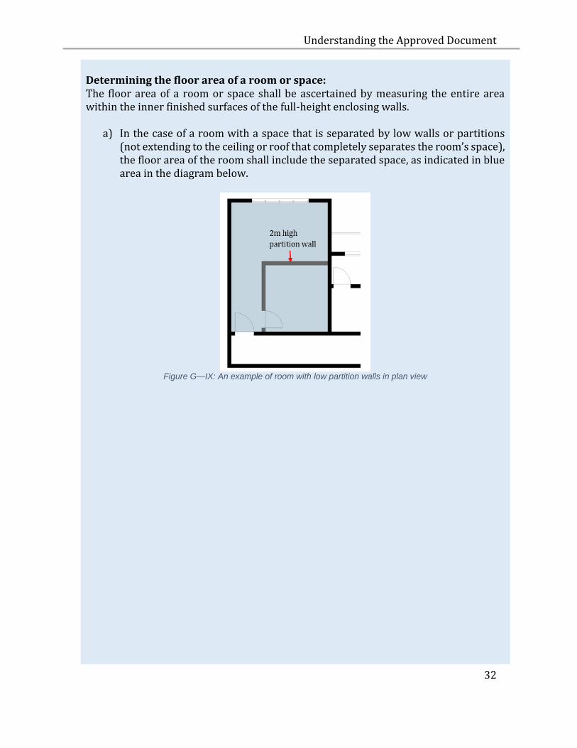
Determining the floor area of a room or space: The floor area of a room or space shall be ascertained by measuring the entire area within the inner finished surfaces of the full-height enclosing walls.
a) In the case of a room with a space that is separated by low walls or partitions (not extending to the ceiling or roof that completely separates the room’s space), the floor area of the room shall include the separated space, as indicated in blue area in the diagram below.
Figure G—IX: An example of room with low partition walls in plan view
Understanding the Approved Document
33
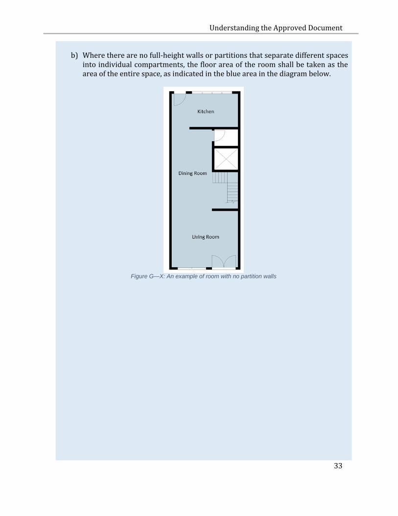
b) Where there are no full-height walls or partitions that separate different spaces
into individual compartments, the floor area of the room shall be taken as the area of the entire space, as indicated in the blue area in the diagram below.
Figure G—X: An example of room with no partition walls
Understanding the Approved Document
34
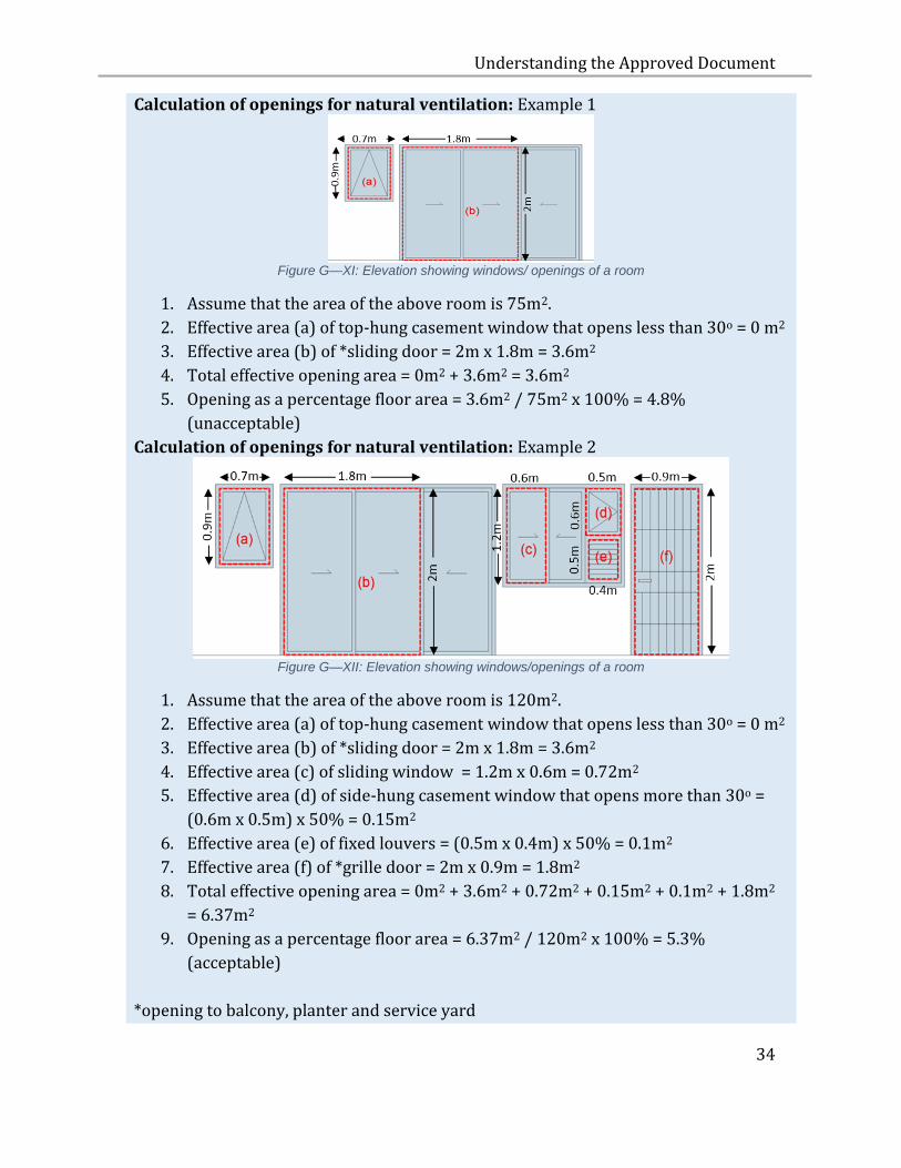
Calculation of openings for natural ventilation: Example 1
Figure G—XI: Elevation showing windows/ openings of a room
1. Assume that the area of the above room is 75m2.
2. Effective area (a) of top-hung casement window that opens less than 30o = 0 m2
3. Effective area (b) of *sliding door = 2m x 1.8m = 3.6m2
4. Total effective opening area = 0m2 + 3.6m2 = 3.6m2
5. Opening as a percentage floor area = 3.6m2 / 75m2 x 100% = 4.8%
(unacceptable)
Calculation of openings for natural ventilation: Example 2
Figure G—XII: Elevation showing windows/openings of a room
1. Assume that the area of the above room is 120m2.
2. Effective area (a) of top-hung casement window that opens less than 30o = 0 m2
3. Effective area (b) of *sliding door = 2m x 1.8m = 3.6m2
4. Effective area (c) of sliding window = 1.2m x 0.6m = 0.72m2
5. Effective area (d) of side-hung casement window that opens more than 30o =
(0.6m x 0.5m) x 50% = 0.15m2
6. Effective area (e) of fixed louvers = (0.5m x 0.4m) x 50% = 0.1m2
7. Effective area (f) of *grille door = 2m x 0.9m = 1.8m2
8. Total effective opening area = 0m2 + 3.6m2 + 0.72m2 + 0.15m2 + 0.1m2 + 1.8m2
= 6.37m2
9. Opening as a percentage floor area = 6.37m2 / 120m2 x 100% = 5.3%
(acceptable)
*opening to balcony, planter and service yard
Understanding the Approved Document
35
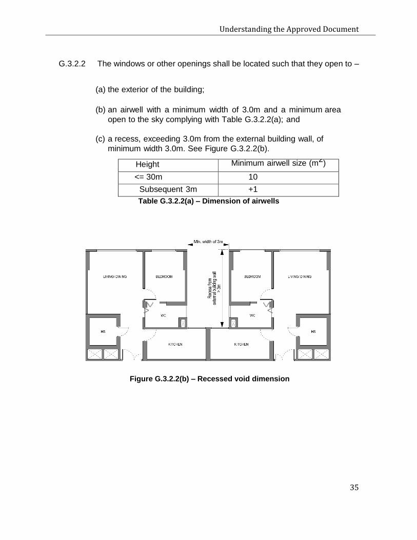
G.3.2.2 The windows or other openings shall be located such that they open to –
(a) the exterior of the building;
(b) an airwell with a minimum width of 3.0m and a minimum area
open to the sky complying with Table G.3.2.2(a); and
(c) a recess, exceeding 3.0m from the external building wall, of
minimum width 3.0m. See Figure G.3.2.2(b).
Height Minimum airwell size (m2)
<= 30m 10
Subsequent 3m +1
Table G.3.2.2(a) – Dimension of airwells
Figure G.3.2.2(b) – Recessed void dimension
Understanding the Approved Document
36
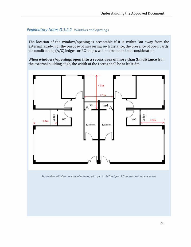
Explanatory Notes G.3.2.2- Windows and openings
The location of the window/opening is acceptable if it is within 3m away from the external facade. For the purpose of measuring such distance, the presence of open yards, air-conditioning (A/C) ledges, or RC ledges will not be taken into consideration. When windows/openings open into a recess area of more than 3m distance from the external building edge, the width of the recess shall be at least 3m.
Figure G—XIII: Calculations of opening with yards, A/C ledges, RC ledges and recess areas
Understanding the Approved Document
37
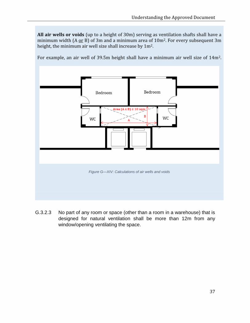
All air wells or voids (up to a height of 30m) serving as ventilation shafts shall have a minimum width (A or B) of 3m and a minimum area of 10m2. For every subsequent 3m height, the minimum air well size shall increase by 1m2. For example, an air well of 39.5m height shall have a minimum air well size of 14m2.
Figure G—XIV: Calculations of air wells and voids
G.3.2.3 No part of any room or space (other than a room in a warehouse) that is
designed for natural ventilation shall be more than 12m from any
window/opening ventilating the space.
Understanding the Approved Document
38
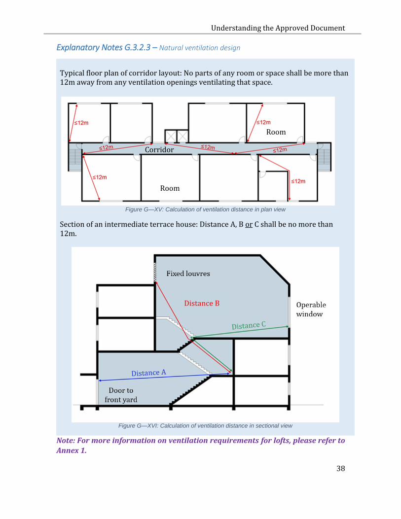
Explanatory Notes G.3.2.3 – Natural ventilation design
Typical floor plan of corridor layout: No parts of any room or space shall be more than 12m away from any ventilation openings ventilating that space.
Figure G—XV: Calculation of ventilation distance in plan view
Section of an intermediate terrace house: Distance A, B or C shall be no more than 12m.
Figure G—XVI: Calculation of ventilation distance in sectional view
Note: For more information on ventilation requirements for lofts, please refer to
Annex 1.
Room
Room
Corridor
Distance B
Understanding the Approved Document
39
H SAFETY FROM FALLING
H.1 OBJECTIVE
H.1.1 The objective of paragraphs H.2.1, H.2.1A and H.2.1B is to protect
people from injury caused by falling from a height.
H.2 PERFORMANCE REQUIREMENT
H.2.1 Where there is a vertical drop in level of 1.0 m or more, appropriate
measures shall be taken to prevent people from falling from a height.
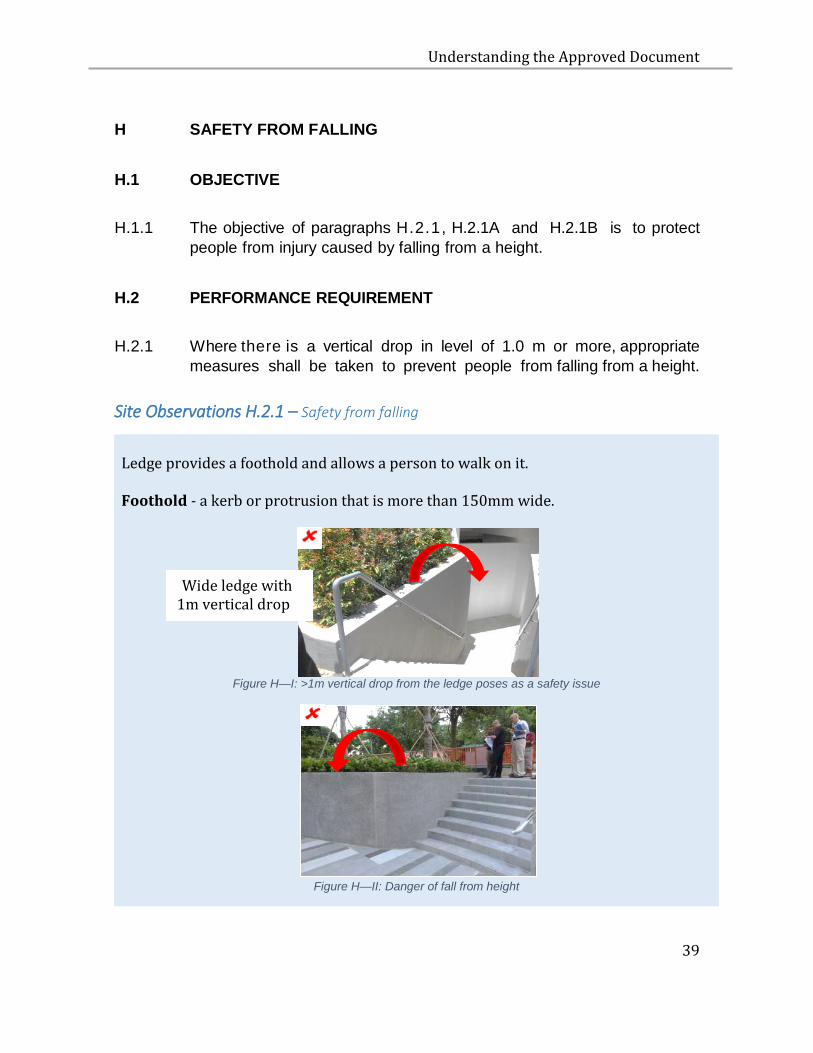
Site Observations H.2.1 – Safety from falling
Ledge provides a foothold and allows a person to walk on it. Foothold - a kerb or protrusion that is more than 150mm wide.
Figure H—I: >1m vertical drop from the ledge poses as a safety issue
Figure H—II: Danger of fall from height
Wide ledge with 1m vertical drop
Understanding the Approved Document
40
H.2.1A Where a barrier is used to prevent falling from a height, the
barrier –
(a) must be sufficiently high to prevent a person from falling over the top of the barrier;
(b) must no have any opening or gap that will allow a person to slip through the barrier; and
(c) must not have any feature that facilitates a person in climbing over the barrier.
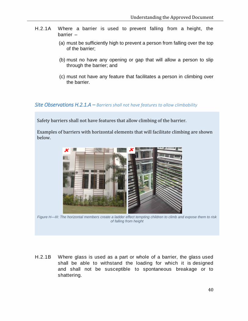
Site Observations H.2.1.A – Barriers shall not have features to allow climbability
Safety barriers shall not have features that allow climbing of the barrier. Examples of barriers with horizontal elements that will facilitate climbing are shown below.
Figure H—III: The horizontal members create a ladder effect tempting children to climb and expose them to risk
of falling from height
H.2.1B Where glass is used as a part or whole of a barrier, the glass used
shall be able to withstand the loading for which it is designed
and shall not be susceptible to spontaneous breakage or to
shattering.
Understanding the Approved Document
41
H.2.2 The requirement in paragraphs H.2.1, H.2.1A and H.2.1B shall not
apply to –
(a) any roof which is accessible for maintenance purposes only and
not easily accessible to the public; and
(b) any area where the provision of a barrier would prevent it from
being used as intended, such as a loading dock or pier, platform
for the loading or unloading of goods, or for boarding or alighting
of passengers, stage for performance or entertainment, golf
driving range, equipment pit and the like.
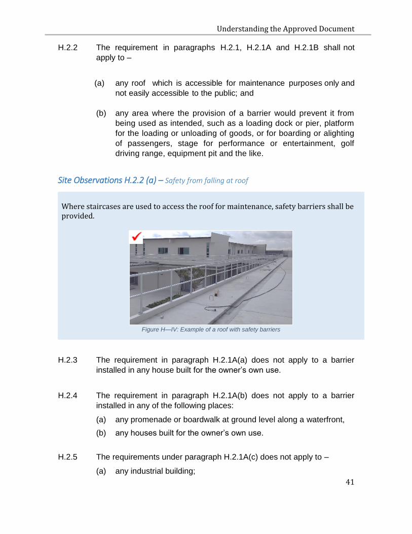
Site Observations H.2.2 (a) – Safety from falling at roof
Where staircases are used to access the roof for maintenance, safety barriers shall be provided.
Figure H—IV: Example of a roof with safety barriers
H.2.3 The requirement in paragraph H.2.1A(a) does not apply to a barrier
installed in any house built for the owner’s own use.
H.2.4 The requirement in paragraph H.2.1A(b) does not apply to a barrier
installed in any of the following places:
(a) any promenade or boardwalk at ground level along a waterfront,
(b) any houses built for the owner’s own use.
H.2.5 The requirements under paragraph H.2.1A(c) does not apply to –
(a) any industrial building;

Understanding the Approved Document
42
(b) any promenade and boardwalk at ground level along a waterfront;
(c) any bay window in a residential unit;
(d) any house built for the owner’s own use.
H.3 ACCEPTABLE SOLUTION
H.3.1 The requirement in paragraphs H.2.1, H.2.1A and H.2.1B is deemed
to be satisfied if a barrier is provided in accordance with the specifications
set out in paragraphs H.3.2 to H.3.5.
H.3.2 HEIGHT OF BARRIER
H.3.2.1 The height of a barrier shall not be less than –
(a) 1m at all locations except for locations indicated in (b)
(b) 900 mm at the lower edge of the window and gallery or balcony with
fixed seating in areas such as theatres, cinemas and assembling
halls.
Note: 1 The height of a barrier is measured vertically from the finished floor level to the top of the barrier.
2 The height of a barrier at the flight of stairs is measured vertically from the pitch line to the top of the barrier.
3 Where a kerb or step with dimensions more than 150mm by 150mm is provided next to a barrier, the height of the barrier shall be measured from the top of the kerb or step.
Understanding the Approved Document
43
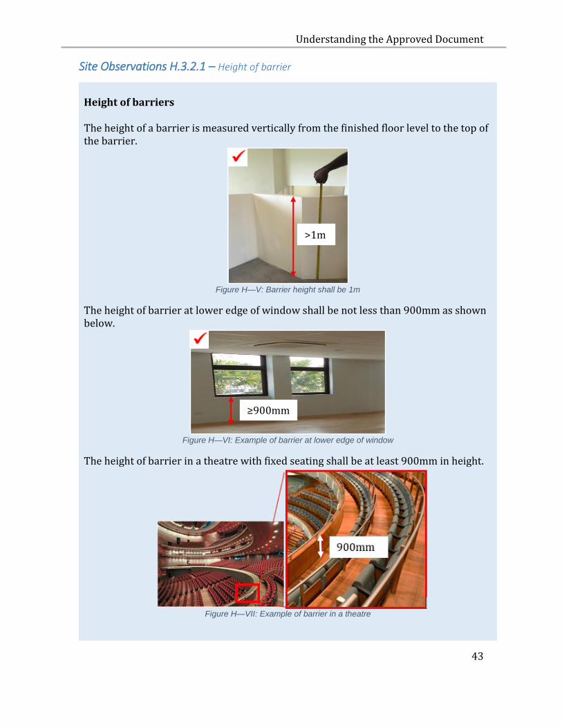
Site Observations H.3.2.1 – Height of barrier
Height of barriers The height of a barrier is measured vertically from the finished floor level to the top of the barrier.
Figure H—V: Barrier height shall be 1m
The height of barrier at lower edge of window shall be not less than 900mm as shown below.
Figure H—VI: Example of barrier at lower edge of window
The height of barrier in a theatre with fixed seating shall be at least 900mm in height.
Figure H—VII: Example of barrier in a theatre
>1m
≥900mm
Understanding the Approved Document
44
H.3.3 HORIZONTAL LOADING AND DESIGN OF GLASS PANEL
BARRIERS
H.3.3.1 A barrier shall be designed to withstand a horizontal loading
determined in accordance with the following Standards –
When adopting Singapore or
British design standards
When adopting Eurocodes
(i) BS 6399: Part 1 – Loading for
buildings. Code of practice for
dead and imposed loads.
(i) SS EN 1991 Actions on structures
– Part 1-1: General actions –
Densities, self-weight, imposed loads
for buildings and the associated
Singapore National Annex.
H.3.3.2 Glass panel barriers shall be designed and installed in
accordance with Section 8 of BS 6180 – Barriers in and about Buildings
– Code of Practice.
H.3.4 SIZE OF OPENING
H.3.4.1 The lowest part of the barrier (being at least 75mm measured from
the finished floor level) shall be built with no gap, in order to prevent
any object from falling through the base of the barrier.
H.3.4.2 The lowest 75mm of the bay window shall not be openable.
H.3.4.3 In non-industrial buildings, the size of any opening or gap in a barrier
shall not be large enough as to permit the passage of a sphere of a
diameter of 100mm.
H.3.4.4 In industrial buildings, the size of any opening or gap in a barrier shall
not be large enough as to permit the passage of a sphere of a diameter
of 150mm.
Understanding the Approved Document
45
H.3.4.4A In areas of maintenance, including plants, equipment rooms, catwalks
or platforms for maintenance, accessible by authorised personnel only
where necessary, the size of the opening or gap in the barrier shall not
be large enough as to permit the passage of a sphere of a diameter of
500mm.
H.3.4.5 For a flight of staircase,
(a) In all buildings, except for industrial buildings, any triangular
opening or void formed around a tread, riser and the bottom
edge of the barrier, the size of any opening or gap shall not be
large enough as to permit the passage of a sphere of a diameter of
150mm.
(b) In all buildings, except for industrial buildings, the gap size
between any two consecutive steps shall not be large enough as to
permit the passage of a sphere of a diameter of 100mm; and
(c) In industrial buildings, the gap size between any two consecutive
steps shall not be large enough as to permit the passage of a sphere
of a diameter of 150mm.
Understanding the Approved Document
46
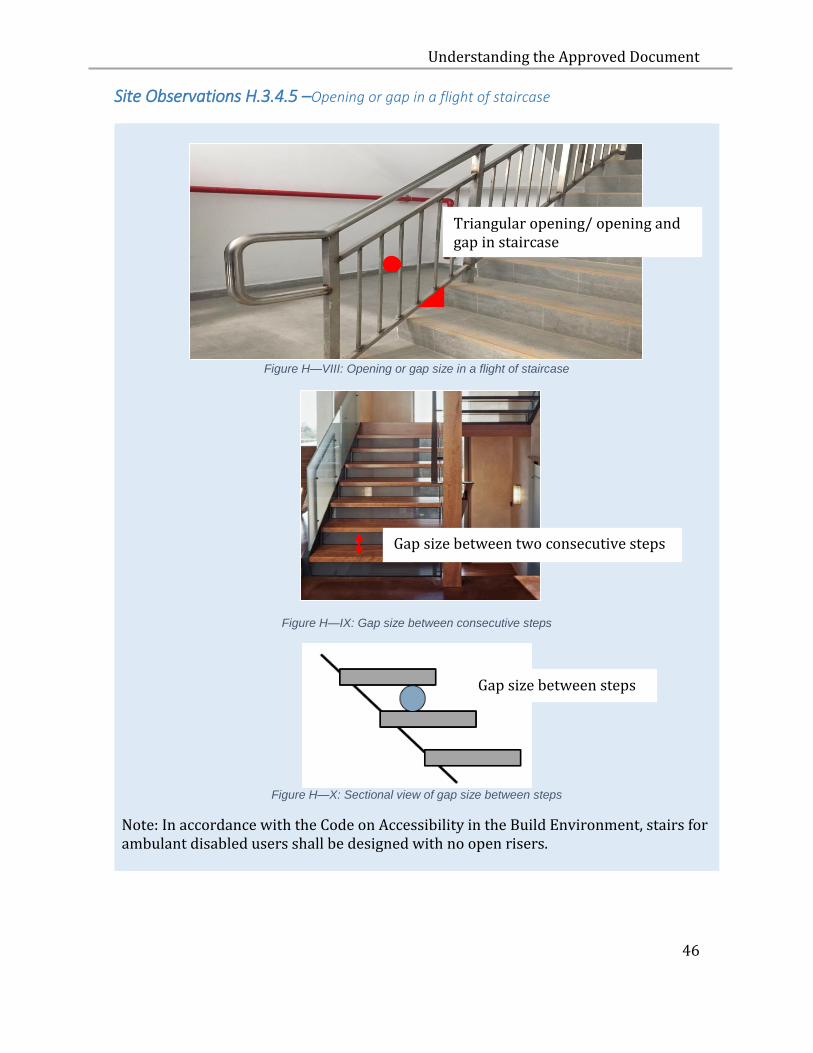
Site Observations H.3.4.5 –Opening or gap in a flight of staircase
Figure H—VIII: Opening or gap size in a flight of staircase
Figure H—IX: Gap size between consecutive steps
Figure H—X: Sectional view of gap size between steps
Note: In accordance with the Code on Accessibility in the Build Environment, stairs for ambulant disabled users shall be designed with no open risers.
Gap size between two consecutive steps
Gap size between steps
Triangular opening/ opening and gap in staircase
Understanding the Approved Document
47
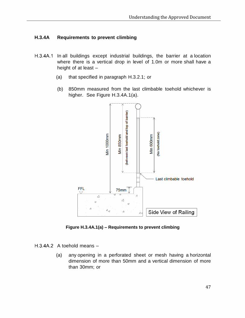
H.3.4A Requirements to prevent climbing
In all buildings except industrial buildings, the barrier at a location
where there is a vertical drop in level of 1.0m or more shall have a
height of at least –
(a) that specified in paragraph H.3.2.1; or
(b) 850mm measured from the last climbable toehold whichever is
higher. See Figure H.3.4A.1(a).
Figure H.3.4A.1(a) – Requirements to prevent climbing
A toehold means –
(a) any opening in a perforated sheet or mesh having a horizontal
dimension of more than 50mm and a vertical dimension of more
than 30mm; or
Understanding the Approved Document
48
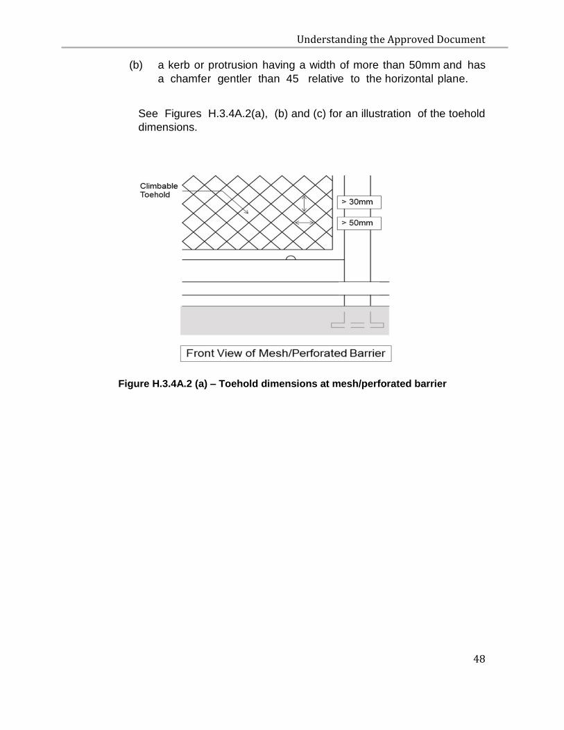
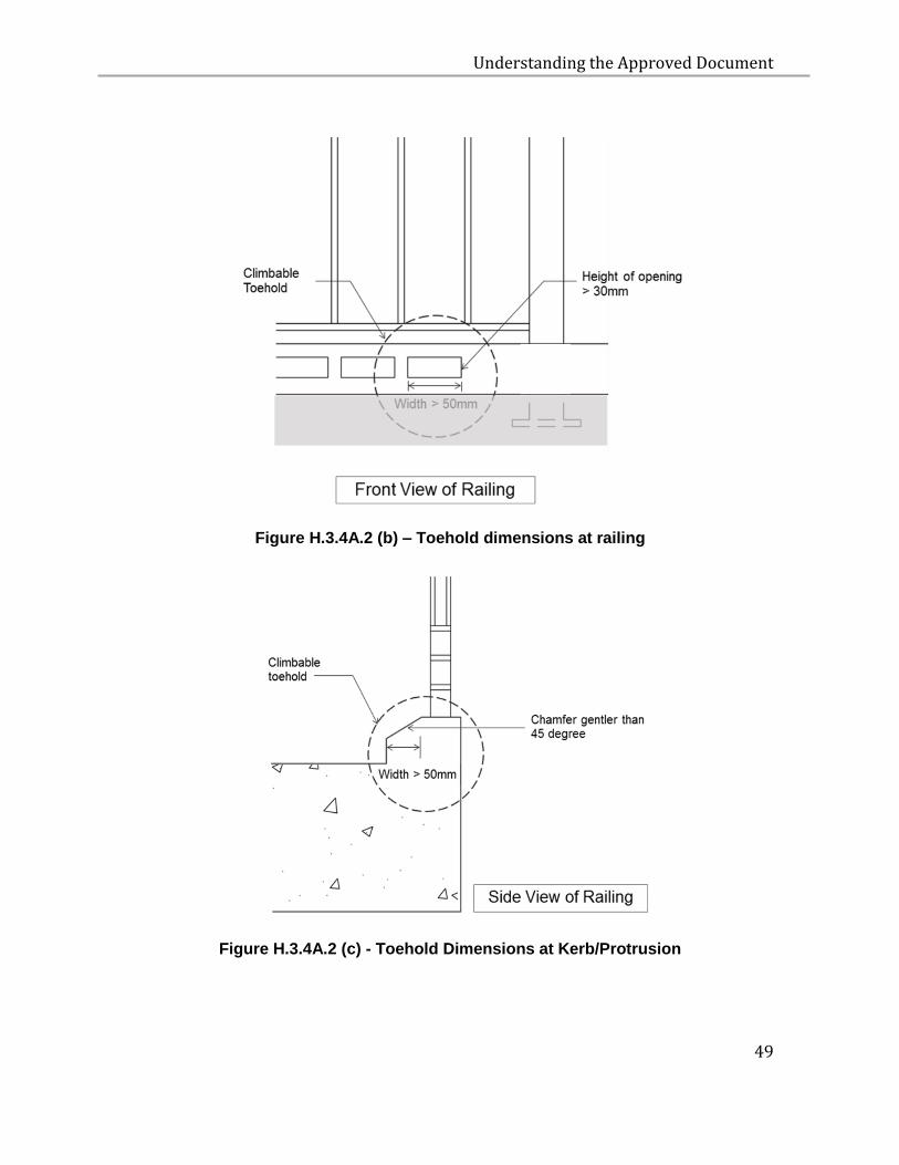
(b) a kerb or protrusion having a width of more than 50mm and has
a chamfer gentler than 45 relative to the horizontal plane.
See Figures H.3.4A.2(a), (b) and (c) for an illustration of the toehold
dimensions.
Figure H.3.4A.2 (a) – Toehold dimensions at mesh/perforated barrier
Understanding the Approved Document
49
Figure H.3.4A.2 (b) – Toehold dimensions at railing
Figure H.3.4A.2 (c) - Toehold Dimensions at Kerb/Protrusion
Understanding the Approved Document
50
A toehold is considered to be climbable if it measures within 600mm
vertically from –
(a) the finished floor level;
(b) a step; or
(c) another climbable toehold.
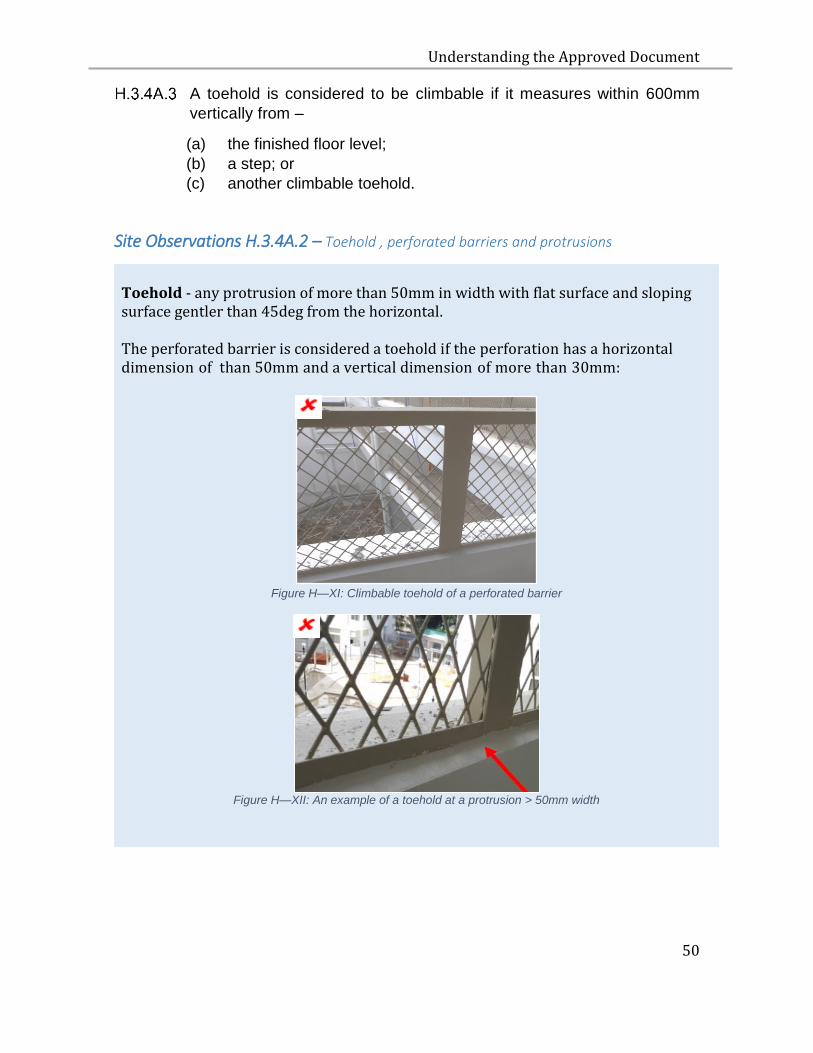
Site Observations H.3.4A.2 – Toehold , perforated barriers and protrusions
Toehold - any protrusion of more than 50mm in width with flat surface and sloping surface gentler than 45deg from the horizontal.
The perforated barrier is considered a toehold if the perforation has a horizontal dimension of than 50mm and a vertical dimension of more than 30mm:
Figure H—XI: Climbable toehold of a perforated barrier
Figure H—XII: An example of a toehold at a protrusion > 50mm width
Understanding the Approved Document
51
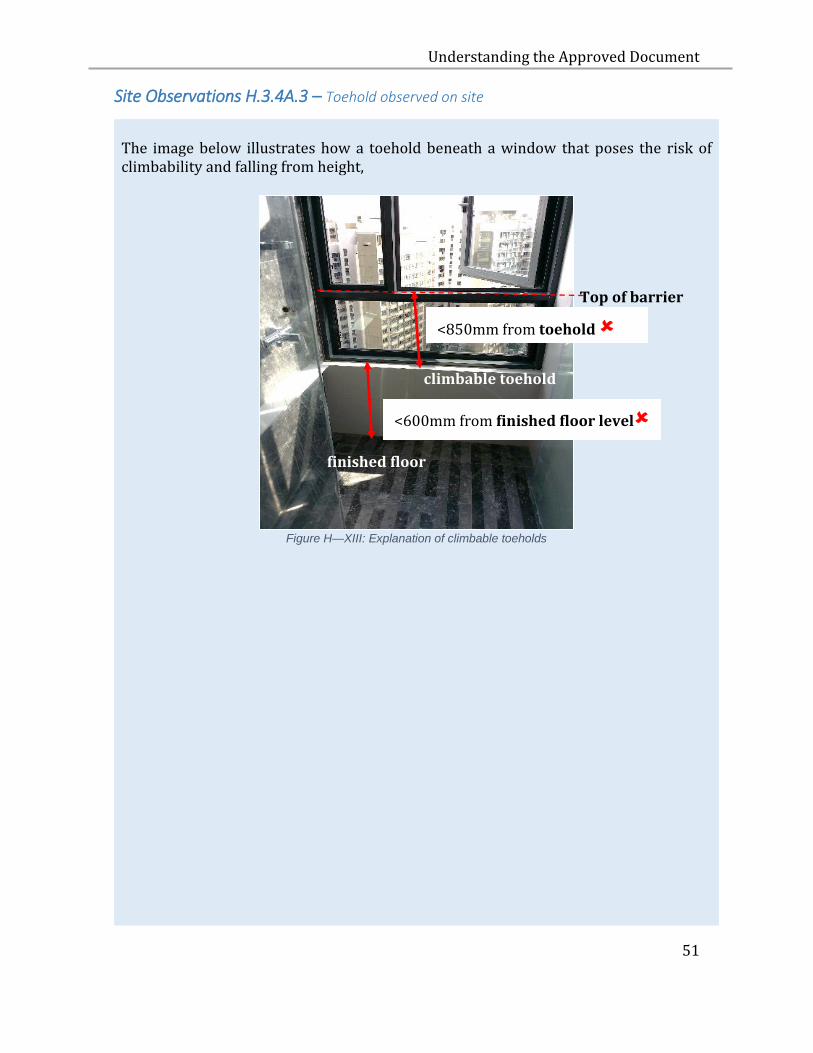
Site Observations H.3.4A.3 – Toehold observed on site
The image below illustrates how a toehold beneath a window that poses the risk of climbability and falling from height,
Figure H—XIII: Explanation of climbable toeholds
climbable toehold
finished floor level
<850mm from toehold
<600mm from finished floor level
Top of barrier
Understanding the Approved Document
52
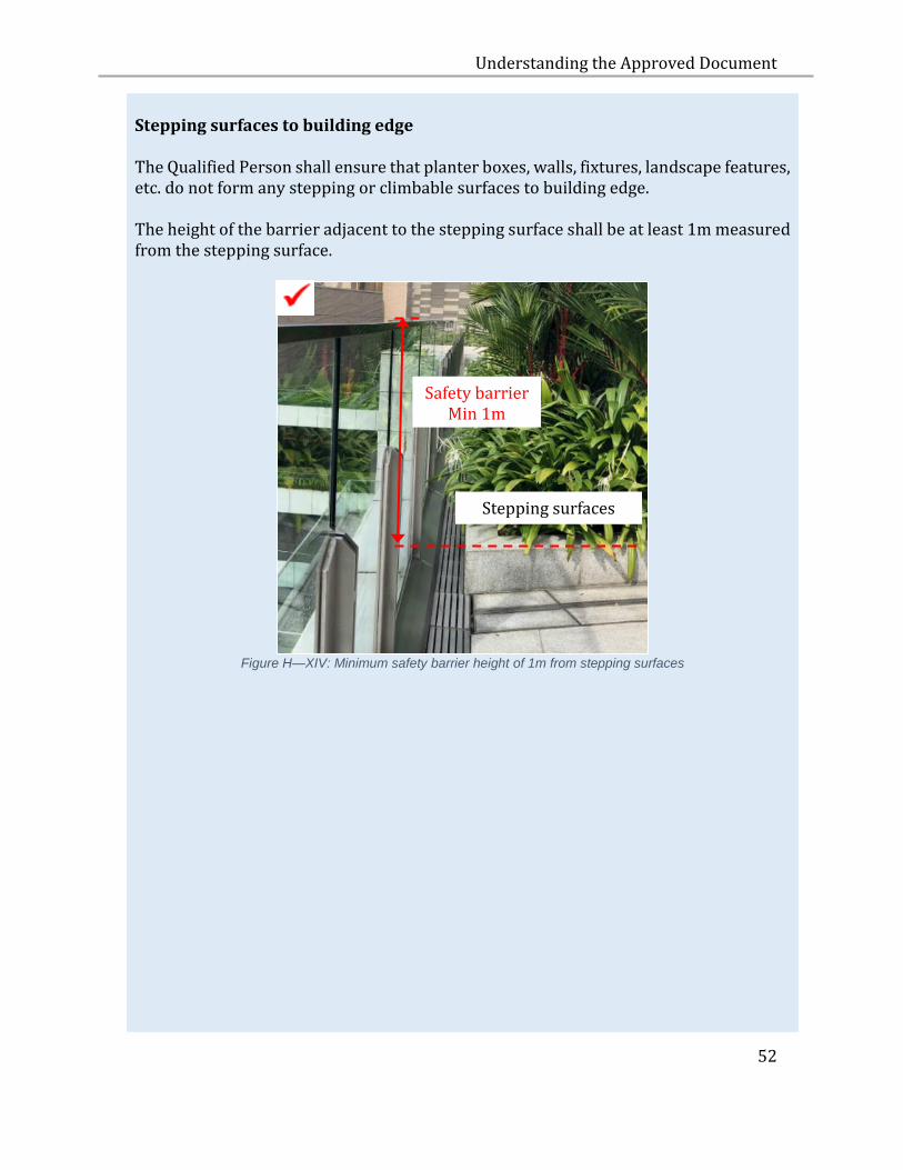
Stepping surfaces to building edge The Qualified Person shall ensure that planter boxes, walls, fixtures, landscape features, etc. do not form any stepping or climbable surfaces to building edge. The height of the barrier adjacent to the stepping surface shall be at least 1m measured from the stepping surface.
Figure H—XIV: Minimum safety barrier height of 1m from stepping surfaces
Stepping surfaces
Safety barrier Min 1m
Understanding the Approved Document
53
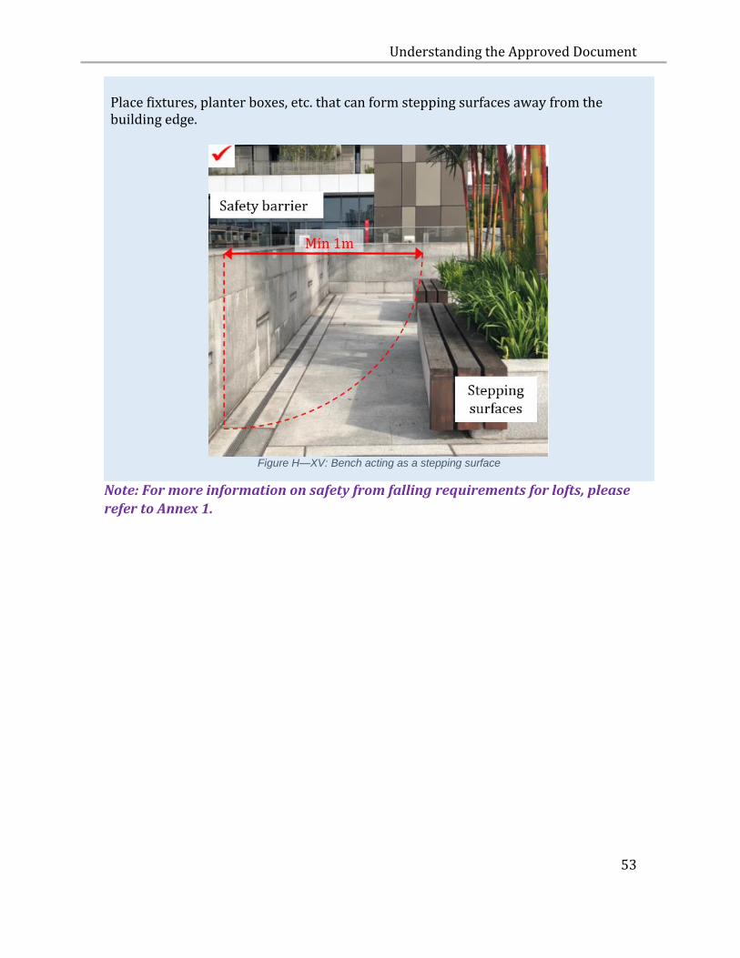
Place fixtures, planter boxes, etc. that can form stepping surfaces away from the building edge.
Figure H—XV: Bench acting as a stepping surface
Note: For more information on safety from falling requirements for lofts, please
refer to Annex 1.
Understanding the Approved Document
54
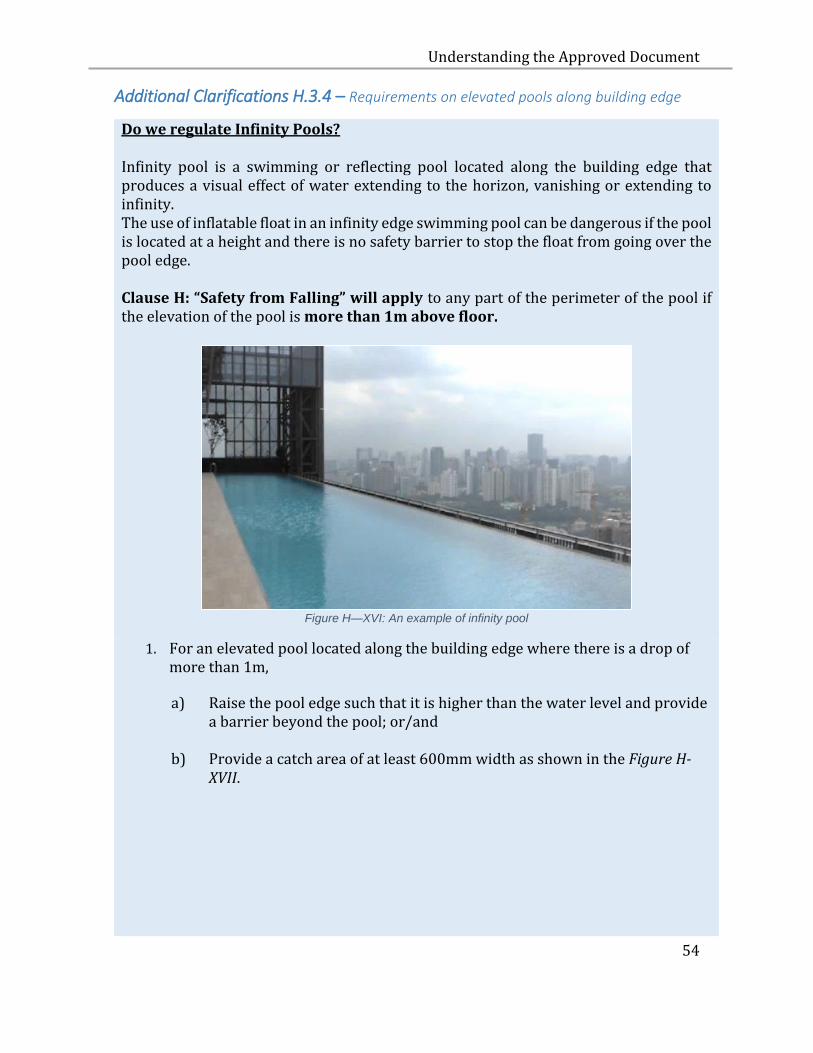
Additional Clarifications H.3.4 – Requirements on elevated pools along building edge
Do we regulate Infinity Pools? Infinity pool is a swimming or reflecting pool located along the building edge that produces a visual effect of water extending to the horizon, vanishing or extending to infinity. The use of inflatable float in an infinity edge swimming pool can be dangerous if the pool is located at a height and there is no safety barrier to stop the float from going over the pool edge. Clause H: “Safety from Falling” will apply to any part of the perimeter of the pool if the elevation of the pool is more than 1m above floor.
Figure H—XVI: An example of infinity pool
1. For an elevated pool located along the building edge where there is a drop of more than 1m,
a) Raise the pool edge such that it is higher than the water level and provide a barrier beyond the pool; or/and
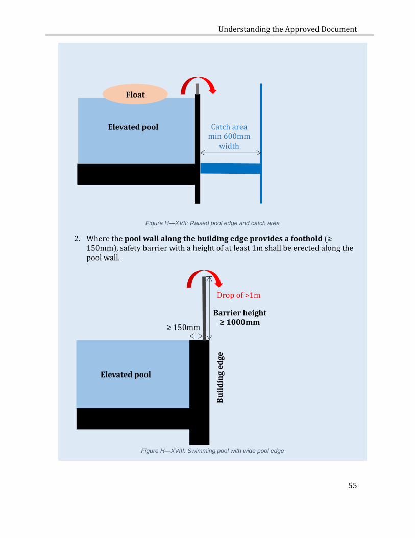
b) Provide a catch area of at least 600mm width as shown in the Figure H-XVII.
Understanding the Approved Document
55
Figure H—XVII: Raised pool edge and catch area
2. Where the pool wall along the building edge provides a foothold (≥ 150mm), safety barrier with a height of at least 1m shall be erected along the pool wall.
Figure H—XVIII: Swimming pool with wide pool edge
Catch area min 600mm
width
Elevated pool
Bu
ild
ing
ed
ge
Barrier height ≥ 1000mm
≥ 150mm
Elevated pool
Drop of >1m
Float
Understanding the Approved Document
56
H.3.5 GLASS BARRIER
H.3.5.1 Where glass is used as a part or whole of a barrier, laminated glass shall
be used.
H.3.5.2 All glass used must comply with SS 341: Specification for Safety Glazing
Materials for Use in Buildings.
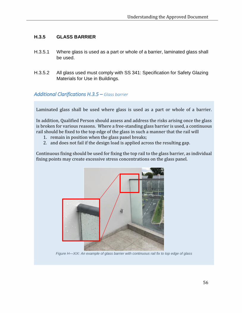
Additional Clarifications H.3.5 – Glass barrier
Laminated glass shall be used where glass is used as a part or whole of a barrier.
In addition, Qualified Person should assess and address the risks arising once the glass is broken for various reasons. Where a free-standing glass barrier is used, a continuous rail should be fixed to the top edge of the glass in such a manner that the rail will
1. remain in position when the glass panel breaks; 2. and does not fail if the design load is applied across the resulting gap.
Continuous fixing should be used for fixing the top rail to the glass barrier, as individual fixing points may create excessive stress concentrations on the glass panel.
Figure H—XIX: An example of glass barrier with continuous rail fix to top edge of glass
Understanding the Approved Document
57
I ENERGY EFFICIENCY
I.1 OBJECTIVE
I.1.1 The objective of paragraphs I.2.1 and I.2.2 is to facilitate efficient use of
energy.
I.2 PERFORMANCE REQUIREMENT
I.2.1 A building shall be designed and constructed with energy
conservation measures to reduce –
(a) Solar heat gain through the roof;
(b) solar heat gain through the building envelope;
(c) air leakage through doors, windows and other openings on the
building envelope;
(d) energy consumption of lighting, air-conditioning and
mechanical ventilation systems; and
(e) energy wastage through adequate provisions of switching means.
I.2.2 Commercial buildings with a gross area of more than 500 m2 shall be
installed or equipped with means to facilitate the collection of energy
consumption data.
I.2.3 The requirement in paragraph I.2.1(a) does not apply to a roof of any
of the following buildings that does not have air-conditioning:
(a) any building with a gross floor area not exceeding 500 square
metres;
(b) any open-sided shed;
(c) any linkway;
Understanding the Approved Document
58
(d) any covered walkway;
(e) any store room and utility room;
(f) any equipment or plant room.
I.3 ACCEPTABLE SOLUTION
I.3.1 The requirements in paragraphs I.2.1 and I.2.2 are deemed to be satisfied
if the design and construction of a building comply with the specifications
set out in paragraphs I.3.2 to I.3.8.
I.3.2 AIR-CONDITIONED BUILDING
I.3.2.1 For all residential buildings with a gross floor area of 2000m2 or more,
the Residential Envelope Transmittance Value (RETV) of the building, as
determined in accordance with the formula set out in the “Code on
Envelope Thermal Performance for Buildings” issued by the
Commissioner of Building Control, shall not exceed 25 W/m2.
I.3.2.2 The requirements in paragraphs I.3.2.1 are deemed to be satisfied if a
residential building with external walls consisting of masonry
construction, satisfies the criteria below:
WWR Bldg <0.3 and SC facade <0.7
Or
WWR Bldg <0.4 and SC facade <0.5
Or
WWR Bldg <0.5 and SC facade <0.43
Understanding the Approved Document
59
Where:
WWR: Window to wall ratio
SC: Shading coefficient of fenestration = SCglass X SCshading device
I.3.2.3 For all non-residential buildings with an aggregate air- conditioned
area of more than 500m2, the Envelope Thermal Transfer Value
(ETTV) of the building, as determined in accordance with the
formula set out in the “Code on Envelope Thermal Performance for
Buildings” issued by the Commissioner of Building Control, shall not
exceed 50 W/m2.
I.3.2.4 In respect of roofs with skylight, the roof thermal transfer value (RTTV)
as determined in accordance with the formula set out in the “Code on
Envelope Thermal Performance for Buildings” issued by the
Commissioner of Building Control, shall not exceed 50 W/m2.
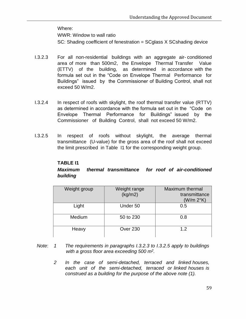
I.3.2.5 In respect of roofs without skylight, the average thermal
transmittance (U-value) for the gross area of the roof shall not exceed
the limit prescribed in Table I1 for the corresponding weight group.
TABLE I1
Maximum thermal transmittance for roof of air-conditioned
building
Note:
1
The requirements in paragraphs I.3.2.3 to I.3.2.5 apply to buildings with a gross floor area exceeding 500 m2.
2 In the case of semi-detached, terraced and linked houses, each unit of the semi-detached, terraced or linked houses is construed as a building for the purpose of the above note (1).
Weight group Weight range (kg/m2)
Maximum thermal transmittance
(W/m 2°K)
Light Under 50 0.5
Medium 50 to 230 0.8
Heavy Over 230 1.2
Understanding the Approved Document
60
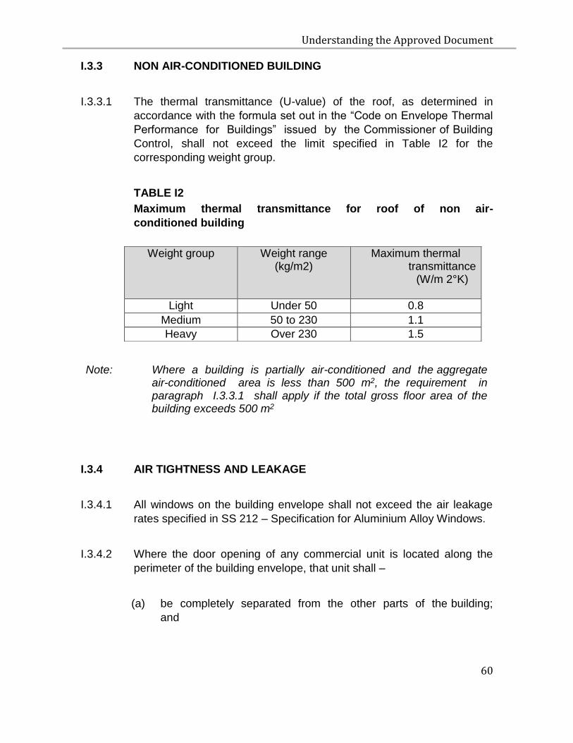
I.3.3 NON AIR-CONDITIONED BUILDING
I.3.3.1 The thermal transmittance (U-value) of the roof, as determined in
accordance with the formula set out in the “Code on Envelope Thermal
Performance for Buildings” issued by the Commissioner of Building
Control, shall not exceed the limit specified in Table I2 for the
corresponding weight group.
TABLE I2
Maximum thermal transmittance for roof of non air-
conditioned building
Note: Where a building is partially air-conditioned and the aggregate air-conditioned area is less than 500 m2, the requirement in paragraph I.3.3.1 shall apply if the total gross floor area of the building exceeds 500 m2
I.3.4 AIR TIGHTNESS AND LEAKAGE
I.3.4.1 All windows on the building envelope shall not exceed the air leakage
rates specified in SS 212 – Specification for Aluminium Alloy Windows.
I.3.4.2 Where the door opening of any commercial unit is located along the
perimeter of the building envelope, that unit shall –
(a) be completely separated from the other parts of the building;
and
Weight group Weight range (kg/m2)
Maximum thermal transmittance
(W/m 2°K)
Light Under 50 0.8
Medium 50 to 230 1.1
Heavy Over 230 1.5
Understanding the Approved Document
61
(b) has its air-conditioning system separated from and
independent of the central system.
Note: 1 The requirements in paragraphs I.3.4.1 and I.3.4.2 do not apply to non air-conditioned buildings.
2 The requirement in paragraph I.3.4.2 also applies to commercial units, the doors of which open into an exterior open space, external corridor, passageway or pedestrian walkway.
I.3.5 AIR-CONDITIONING SYSTEM
I.3.5.1 Where the cooling capacity of any air-conditioning system exceeds
30 kW, the equipment shall comply with the relevant provisions of SS 530
- Code of Practice for Energy Efficiency Standard for Building Services
and Equipment.
I.3.6 ARTIFICIAL LIGHTING
I.3.6.1 The maximum lighting power budget in a building shall comply with SS
530 - Code of Practice for Energy Efficiency Standard for Building
Services and Equipment.
I.3.7 SWITCHING CONTROL
I.3.7.1 Air-conditioning system shall be equipped with manual switches, timers
or automatic controllers for shutting off part of the air- conditioning
system during periods of non-use or reduced heat load.
I.3.7.2 Lighting control for artificial lighting shall be provided in
accordance with SS 530 - Code of Practice for Energy Efficiency
Standard for Building Services and Equipment.
.
I.3.7.3 In any hotel building, a control device acceptable to the
Commissioner of Building Control, shall be installed in every
guestroom for the purpose of automatically switching off the lighting and
reducing the air-conditioning when a guestroom is not occupied.

Understanding the Approved Document
62
I.3.8 ENERGY AUDITING
I.3.8.1 For buildings used as offices, shops, hotels or a combination thereof,
suitable means for the monitoring of energy consumption shall be
provided to all incoming power supply to a building and the sub-circuits
serving –
(a) a central air-conditioning system;
(b) a major mechanical ventilation system;
(c) a vertical transportation system;
(d) a water pumping system;
(e) the general power supply to tenancy areas;
(f) the general lighting supply to tenancy areas;
(g) the general power supply to owner’s premises; and
(h) the general lighting supply to owner’s premises.
Understanding the Approved Document
63
J ROOF
J.1 OBJECTIVE
J.1.1 The objective of paragraph J.2.1 is to protect the roof of semi- detached
houses, terraced houses and linked houses from physical damage when
repairs, alterations or additions to the roof of an adjoining house are
being carried out.
J.2 PERFORMANCE REQUIREMENT
J.2.1 The roof shall be designed and constructed such that the roof of every
house is separate and independent of each other.
J.3 ACCEPTABLE SOLUTION
J.3.1 The requirement in paragraph J.2.1 is deemed to be satisfied if the party
wall is extended above the level of the roof so that each roof is separate
and independent of the roof of the adjoining house.
Understanding the Approved Document
64
K LIFTS AND ESCALATORS
K.1 OBJECTIVE
K.1.1 The objective of paragraphs K.2.1 and K.2.2 is to provide a
convenient means of vertical transportation and to protect people
from injury while using the lifts or escalators.
K.2 PERFORMANCE REQUIREMENT
K.2.1 Lifts and escalators shall –
(a) move people safely; and
(b) not produce excessive acceleration or deceleration.
K.2.2 A building comprising 5 or more storeys (including the ground level)
shall be provided with one or more passenger lifts.
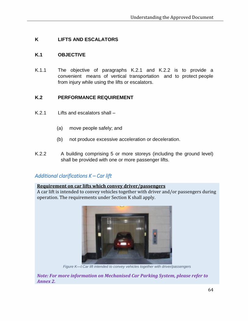
Additional clarifications K – Car lift
Requirement on car lifts which convey driver/passengers A car lift is intended to convey vehicles together with driver and/or passengers during operation. The requirements under Section K shall apply.
Figure K—I:Car lift intended to convey vehicles together with driver/passengers
Note: For more information on Mechanised Car Parking System, please refer to Annex 2.
Understanding the Approved Document
65
K.2.3 All lift interior fittings and fixtures must be securely fastened by
appropriate mechanical fasteners.
K.2.4 The requirement in paragraph K.2.1 does not apply to any stairlift or
vertical platform lift that –
(a) has a maximum vertical displacement of less than 1,000 mm when the lift is in operation;
(b) has a maximum obstruction force of less than 150 Newtons when the lift is in operation; and
(c) serves a single residential unit.
K.2.5 In paragraph K.2.3, “stairlift” and “vertical platform lift” have the same
meanings given to them in regulation 2(1) of the Building Maintenance
and Strata Management (Lift, Escalator and Building Maintenance)
Regulations 2016 (G.N. No. S 348/2016).
K.3 ACCEPTABLE SOLUTION
K.3.1 The requirements in paragraphs K.2.1 and K.2.2 are deemed to be
satisfied if –
(a) the lifts are designed and installed:
(i) in accordance with the requirements of SS 550 - Code
of Practice for Installation, Operation and Maintenance of
Electric Passenger and Goods Lifts;
(ii) with light curtain installed at the lift door as a door protective
device that shall automatically initiate reopening of the door(s)
in the event of a person crossing the entrance during the
closing movement, and that the light curtain:
Understanding the Approved Document
66
a. shall cover the door opening over the distance between at least 25 mm and 1600 mm above the car door sill;
b. shall be capable of detecting obstacles of minimum 50 mm diameter;
c. may be rendered inoperative in the last 20 mm of door closing gap; and
d. shall have its nudging mode de-activated if nudging mode is provided.
(iii) with a telephone, intercom system or any other communication device that enables notification or direct communication with personnel who can initiate an emergency response;
(iv) with a video recorder that has the following minimum specifications – a. Capacity to record 24 hours a day, 7 days a week;
b. Capture the lift car, lift car door(s) and in-car floor
indicator;
c. Frame rate of at least 6 frames per second;
d. Video resolution of at least 352 x 240 pixels or CIF CCTV resolution; and
e. Storage of video footage of at least 30 days;
and
(b) the escalators are designed and installed:
(i) in accordance with SS 626 - Code of Practice for Design,
Installation and Maintenance of Escalators and Moving
Walks;
(ii) with means to limit or detect the riser end of the step being
displaced upward by more than 5mm at the upper and lower
transition curves at or prior to the point of tangency of the
horizontal and curved track. When the upward displacement
exceeds 5mm, the means shall cut off the power to the
Understanding the Approved Document
67
driving machine and brake and stop the escalator before the
detected step reaches the combplate with any load up to
brake rated load with escalator running; and
(iii) with a video recorder that has the following minimum
specifications –
a. Capacity to record 24 hours a day, 7 days a week;
b. Capture the entire length of the escalator;
c. Frame rate of at least 6 frames per second;
d. Video resolution of at least 352 x 240 pixels; or
e. CIF CCTV resolution; and
f. Storage of video footage of at least 30 days.
For the purposes of this part: “light curtain” means an opto-electronic device that is usually mounted at the lift doors to detect the presence of objects in the path of its light rays.
K.3.2 The requirements in paragraphs K2.1 are deemed to be satisfied if
vertical platform lifts and stair lifts which are primarily designed for
persons with impaired mobility are designed, installed and operated in
accordance with the requirements of –
(a) EN 81-41 – Safety rules for the construction and installation of lifts
– Special lifts for the transport persons and goods. Part 41: Vertical
platforms intended for use by persons with impaired mobility; or
(b) EN 81-40 – Safety rules for the construction and installation of lifts
– Special lifts for the transport of persons and goods. Part 40:
Stairlifts and inclined lifting platforms intended for persons with
impaired mobility; or
(c) ASME 18.1 – Safety standard for platform lifts and stairway
chairlifts; or
Understanding the Approved Document
68
(d) Other relevant standards which are acceptable to the Commissioner
of Building Control.
For the purposes of this part:
“stairlift” means a motorised platform or seat installed in a stairway, which traverses the stairs when activated; and “vertical platform lift” means a vertical lifting platform intended for use by people with impaired mobility, with or without wheelchair, travelling vertically between predefined levels along a guided path.
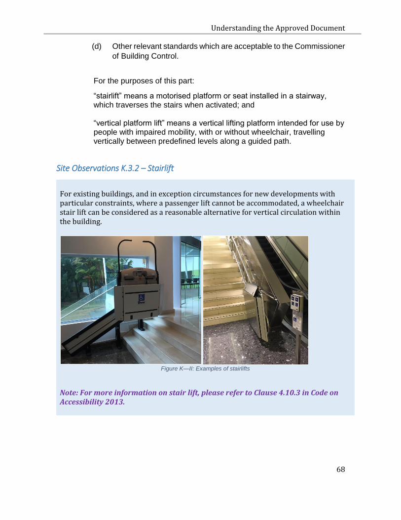
Site Observations K.3.2 – Stairlift
For existing buildings, and in exception circumstances for new developments with particular constraints, where a passenger lift cannot be accommodated, a wheelchair stair lift can be considered as a reasonable alternative for vertical circulation within the building.
Figure K—II: Examples of stairlifts
Note: For more information on stair lift, please refer to Clause 4.10.3 in Code on Accessibility 2013.
Understanding the Approved Document
69
K.3.3 The requirements in paragraph K2.1 are deemed to be satisfied if home
lifts are designed, installed and operated in accordance with the
requirements of –
(a) the SS 550 - Code of Practice for Installation, Operation and
Maintenance of Electric Passenger and Goods Lifts; or
(b) other relevant standards which are acceptable to the Commissioner
of Building Control.
For the purposes of this part:
“home lift” means a lift, not being common property, installed in a private home solely for the use of its occupants.
Understanding the Approved Document
70
L LIGHTNING PROTECTION
L.1 OBJECTIVE
L.1.1 The objective of paragraph L.2.1 is to protect a building from the direct
effects of lightning strike and to protect its occupants from the risk of
lightning current being discharged through the building.
L.2 PERFORMANCE REQUIREMENT
L.2.1 A lightning protection system shall be capable of protecting the building
and its occupants from the effects of lightning strike.
L.3 ACCEPTABLE SOLUTION
L.3.1 The requirement in paragraph L.2.1 is deemed to be satisfied if the
lightning protection system is designed and installed in accordance with
SS 555 - Code of Practice for Protection Against Lightning.
Understanding the Approved Document
71
Additional Clarifications L – Lightning Protection System Design
Good Practices in Lightning Protection System Design (LPS)
Habitable Rooftop Spaces (e.g. roof gardens, penthouse terraces)
1. Typically, rooftop spaces are intended to be accessed only for maintenance purposes. With increasing prevalence of building designs with habitable rooftop spaces, e.g. gardens, penthouse open terrace, car park and amenities. It is important that the LPS design of such buildings take into account such habitable rooftop spaces so as to protect occupants and users of the buildings against the risk of lightning.
2. For such habitable rooftop spaces, Architects need to work closely with the Electrical Engineer and Structural Engineer to ensure that these spaces are designed in accordance with the requirements of SS555, similar to any other habitable open spaces. LPS provision should be carefully considered in the initial design of a building, to integrate both architectural and structural elements into the LPS design. In doing so, this will improve the overall aesthetic of the architectural design and the effectiveness of the LPS.
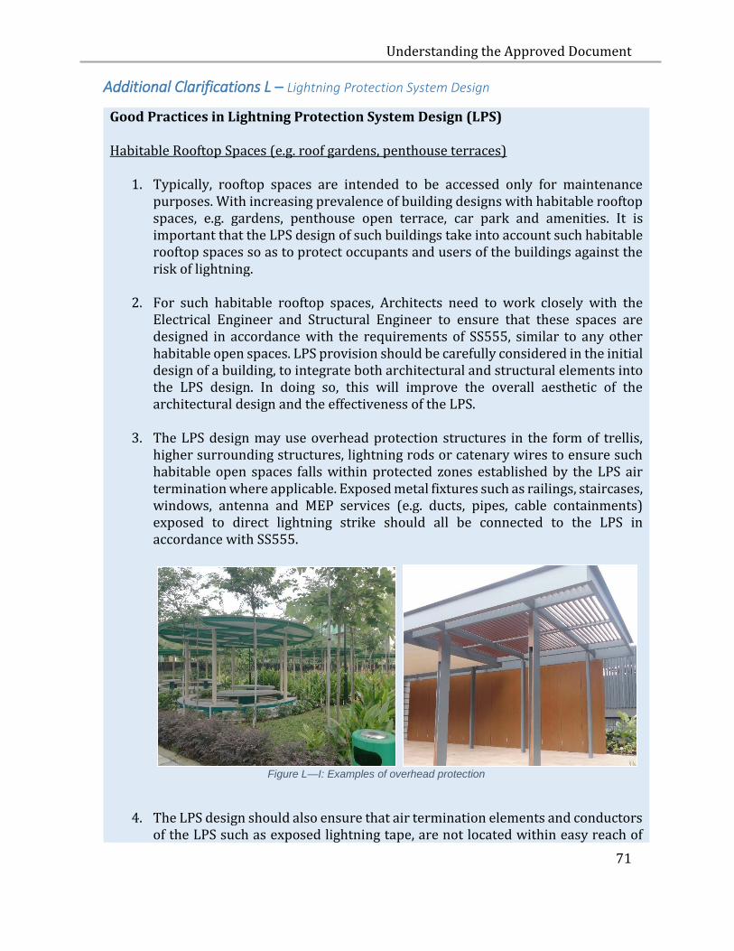
3. The LPS design may use overhead protection structures in the form of trellis, higher surrounding structures, lightning rods or catenary wires to ensure such habitable open spaces falls within protected zones established by the LPS air termination where applicable. Exposed metal fixtures such as railings, staircases, windows, antenna and MEP services (e.g. ducts, pipes, cable containments) exposed to direct lightning strike should all be connected to the LPS in accordance with SS555.
Figure L—I: Examples of overhead protection
4. The LPS design should also ensure that air termination elements and conductors of the LPS such as exposed lightning tape, are not located within easy reach of
Understanding the Approved Document
72
users of these habitable rooftop spaces. Where building design poses constraints, insulation of exposed lightning tape should be provided in accordance with SS555 to prevent direct user contact.
Protection of vertical sides of tall buildings
1. For tall buildings, protection against lightning flashes to the vertical sides of the building with air termination system shall be provided down to a height of 48m in accordance with SS555. The LPS design shall also ensure that every lateral external metallic fixtures (windows, balcony railing, façade) touched by the rolling sphere is bonded to the LPS.
Use of Aluminium Tape
2. Aluminium tape is used widely in local industry practice as LPS conductors in air termination and down conductor system. While not required for mandatory compliance, SS555 advises that aluminium tape should not be attached directly to calcareous building surfaces such as concrete, limestone and plaster as this may hasten the corrosion of the aluminium tape. Additionally, SS555 specifically prohibits the embedding of bare aluminium tape within concrete elements of the building and in earth except if these are completely sleeved with a durable, close-fitting insulating sleeve.
3. As a precaution, mitigation measures in the LPS design should be taken to
prevent the direct contact of the aluminium tape with bare calcareous building surfaces as far as possible, such as with the use of saddles at closer intervals or painting of the surfaces. Alternatively, SS555 advises that the potential corrosion effect may be reduced through increases in material size, using corrosion resistive components, or taking other corrosion protection measures. During the lifecycle of the building, more regular inspection intervals of the LPS than the recommended intervals required under SS555 may be implemented to ensure the continued integrity of the LPS.
Maintaining proper records of LPS during construction
1. As a good practice, the developer and the Qualified Person appointed to supervise the installation of the LPS should co-ordinate with the main builder to keep and maintain proper records of the following documents throughout the project. a) LPS as-built plans endorsed by the QP (electrical). b) Photos of all concealed equipotential bonding between metal fixtures, steel
rebars of concrete and LPS. Metal fixtures may include railings, staircases, windows, antennae, façade and M&E services (e.g. ducts, pipes, cable containments).
c) Earth Resistance & Continuity Test Form d) LPS Material Test Report [Test in accordance with EN50164]
Understanding the Approved Document
73
Regular Inspection and Maintenance of LPS, Operation & Maintenance (O&M) Manual
1. Building owners, MCSTs and facility managers are reminded to conduct regular
inspection and maintenance of the LPS in accordance with the requirements specified under SS555, to ensure continued integrity of the LPS throughout the building’s life cycle. As-built LPS drawings and Test Records should be made available to the person responsible to maintain the LPS.
2. Should there be extensions or alterations to the building, a Professional
Electrical Engineer should be appointed to verify that the LPS protects the new areas, and to enhance the LPS to protect these new areas where necessary, in accordance with SS555.
3. LPS’s documents should be prepared and filed in the M&E O&M Manual to
facilitate LPS inspections and maintenance. They should contain sufficient information to guide the inspector through the inspection process so that all areas of importance are documented. Some of the documents are Certificate of Supervision of Lightning Protection System, As-Built Drawings, Test Records including photographs of all concealed equipotential bonding between metal fixtures, steel rebars of concrete and LPS.
4. The LPS should be maintained regularly to ensure that it does not deteriorate
but continues to fulfil the requirements in accordance to SS555 to which it was originally designed. Any alteration works to the existing LPS should be incorporated into the O&M Manual.
Understanding the Approved Document
74
M SAFETY OF WINDOWS
M.1 OBJECTIVE
M.1.1 The objective of paragraphs M.2.1 and M.2.2 is to protect people
from injury caused by falling windows.
M.2 PERFORMANCE REQUIREMENT
M.2.1 A window system shall be adequately designed and constructed with
appropriate materials for its intended use.
M.2.2 A window system shall have –
(a) window components, including fasteners, fixings, hinges and stays
of adequate number, size and strength to safely support the weight
of the window system and other loads imposed on it;
(b) a structural frame profile that is of adequate size and strength
and adequately reinforced at locations where screws or rivets are to
be affixed; and
(c) features and components to prevent the window from detaching,
dislodging or falling during its intended use.
M.3 ACCEPTABLE SOLUTION
M.3.1 In the case of aluminium alloy window, the requirements in
paragraphs M.2.1 and M.2.2 are deemed to be satisfied if such window
is designed and constructed in accordance with SS 212 – Specification
for Aluminium Alloy Windows.

Understanding the Approved Document
75
Site Observations M.2.2
Examples of window components:
1. Fasteners- Screws and rivets made of stainless steel
Stainless steel screws Aluminium rivets
Stainless steel rivets
Figure M—I: Casement windows
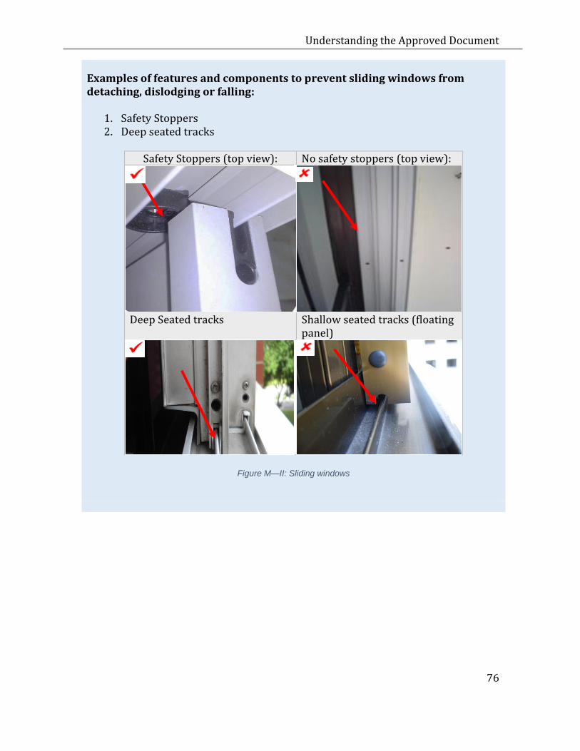
Understanding the Approved Document
76
Examples of features and components to prevent sliding windows from detaching, dislodging or falling:
1. Safety Stoppers 2. Deep seated tracks
Safety Stoppers (top view): No safety stoppers (top view):
Deep Seated tracks Shallow seated tracks (floating panel)
Figure M—II: Sliding windows

Understanding the Approved Document
77
N USE OF GLASS AT HEIGHT
N.1 OBJECTIVE
N.1.1 The objective of paragraph N2 is to protect persons from injury cause by
spontaneous breakage of glass elements at height and by falling glass
panels resulting from bond failure of structural sealant.
N.2 PERFORMANCE REQUIREMENT
N.2.1 Where glass is used as a part or whole of the facade, roof, canopy
or other type of overhead glazing of a building located at height of 2.4
metres or more, whether situated within the interior or forming the exterior
of a building, appropriate measures shall be taken to minimise the risk of
injury to people in the event of spontaneous breakage of such glass
elements.
N.2.2 Where structural sealant glazing is used in a glass curtain wall or other
glass installation located at a height of 2.4 metres or more, whether
situated within the interior or forming the exterior of a building,
appropriate measures shall be taken to minimise the risk of injury to
people in the event of falling glass panels resulting from bond failure of
the structural sealant.
N.3 ACCEPTABLE SOLUTION
N.3.1 The requirement in paragraphs N.2.1 is deemed to be satisfied if the
specifications set out in paragraphs N.3.2 to N.3.4 are complied with.
N.3.2 Float (or annealed) glass, heat strengthened glass, laminated glass
or other type of glass that is not prone to spontaneous breakage shall
be used as the glass material at height.
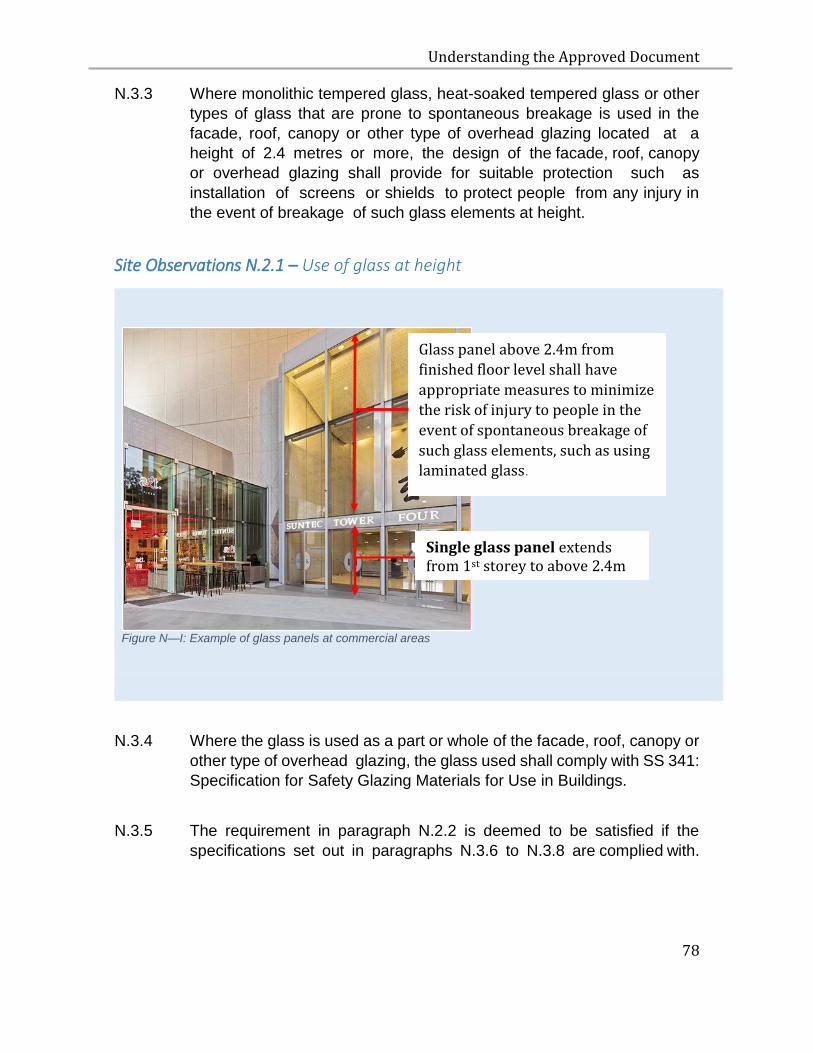
Understanding the Approved Document
78
N.3.3 Where monolithic tempered glass, heat-soaked tempered glass or other
types of glass that are prone to spontaneous breakage is used in the
facade, roof, canopy or other type of overhead glazing located at a
height of 2.4 metres or more, the design of the facade, roof, canopy
or overhead glazing shall provide for suitable protection such as
installation of screens or shields to protect people from any injury in
the event of breakage of such glass elements at height.
Site Observations N.2.1 – Use of glass at height
Figure N—I: Example of glass panels at commercial areas
N.3.4 Where the glass is used as a part or whole of the facade, roof, canopy or
other type of overhead glazing, the glass used shall comply with SS 341:
Specification for Safety Glazing Materials for Use in Buildings.
N.3.5 The requirement in paragraph N.2.2 is deemed to be satisfied if the
specifications set out in paragraphs N.3.6 to N.3.8 are complied with.
Glass panel above 2.4m from
finished floor level shall have
appropriate measures to minimize
the risk of injury to people in the
event of spontaneous breakage of
such glass elements, such as using laminated glass
Single glass panel extends from 1st storey to above 2.4m
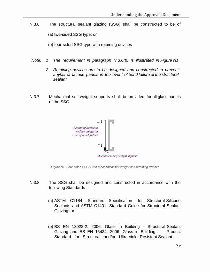
Understanding the Approved Document
79
N.3.6 The structural sealant glazing (SSG) shall be constructed to be of
(a) two-sided SSG type; or
(b) four-sided SSG type with retaining devices
Note: 1 The requirement in paragraph N.3.6(b) is illustrated in Figure N1
2 Retaining devices are to be designed and constructed to prevent anyfall of facade panels in the event of bond failure of the structural sealant.
N.3.7 Mechanical self-weight supports shall be provided for all glass panels
of the SSG.
Figure N1- Four-sided SSGS with mechanical self-weight and retaining devices
N.3.8 The SSG shall be designed and constructed in accordance with the
following Standards –
(a) ASTM C1184: Standard Specification for Structural Silicone
Sealants and ASTM C1401: Standard Guide for Structural Sealant
Glazing; or
(b) BS EN 13022-2: 2006: Glass in Building - Structural Sealant
Glazing and BS EN 15434: 2006: Glass in Building – Product
Standard for Structural and/or Ultra-violet Resistant Sealant.

Understanding the Approved Document
80
O PROTECTION FROM INJURY BY VEHICLES IN BUILDINGS
O.1 OBJECTIVE
O.1.1 The objectives of paragraphs O.2.1 and O.2.2 are to protect people
from injury caused by a vehicle breaching designated spaces for
vehicular access in a building.
O.2 PERFORMANCE REQUIREMENT
O.2.1 Where the whole or part of a floor of a building allows vehicular access,
such as a vehicle park or a ramp or route for vehicular access,
appropriate barriers shall be installed to prevent vehicles from breaching
the perimeter of the floor of the building.
O.2.2 Where any part of a building allows vehicular access near an area where
people are likely to be present, such as passenger pick-up point, vehicle
park lift lobby and the like, appropriate measures shall be taken to
prevent vehicles from encroaching into such areas.
O.3 ACCEPTABLE SOLUTION
O.3.1 The requirements in paragraphs O.2.1 and O.2.2 are deemed to be
satisfied if a barrier is provided in accordance with the specifications set
out in paragraph O.3.2.
O.3.2 HORIZONTAL LOADING OF BARRIER
O.3.3 The vehicular barrier should be capable of resisting forces set out in
Loading for Buildings. Code of Practice for Dead and Imposed Loads BS
6399-Part 1; and SS EN 1991.
Understanding the Approved Document
81
P DAYLIGHT REFLECTANCE
P.1 OBJECTIVE
P.1.1 The objective of paragraph P.2.1 is to protect occupants of buildings in
the vicinity of a building from loss of amenity caused by the reflection of
sunlight off the external surface of that building, arising from the use of
materials with high daylight reflectance.
P.2 PERFORMANCE REQUIREMENT
P.2.1 The external surface (including a roof) of a building must be designed
and constructed in a manner such that any reflection of sunlight off the
external surface of the building does not result in loss of amenity to
occupants of other buildings in the vicinity of that building.
P.3 ACCEPTABLE SOLUTION
P.3.1 The requirement in paragraph P.2.1 is deemed to be satisfied if the
specifications set out in paragraphs P.3.2 to P.3.3 are complied with.
P.3.2 The material used for the building work is deemed acceptable if -
(a) The glass for the building work has a daylight reflectance not
exceeding 20%
(b) For the use of any material, other than glass, for the building work
on –
(i) the façade of the building has a specular reflectance not
exceeding 10%
(ii) the roof, inclined at an angle of not exceeding 20 degrees
from the horizontal plane, of the building has a specular
reflectance not exceeding 10%
Understanding the Approved Document
82
(iii) the roof, inclined at an angle of more than 20 degrees from
the horizontal plane, of the building has a daylight reflectance
not exceeding 20% and a specular reflectance not exceeding
10%
(c) Emulsion paint on plastered or concrete surfaces which has a
specular reflectance not exceeding 10%
Note: 1 For the purpose of (b)(ii) and b(iii), in any building where the façade and the roof continue seamlessly, the area above the last finished floor will be considered the roof.
2 Daylight reflectance is the sum of specular reflectance and diffuse reflectance.
P.3.3 The testing of reflectance values for any material shall be conducted in
accordance with ASTM E903: Standard Test Method for Solar
Absorptance, Reflectance, and Transmittance of Materials Using
Integrating Spheres, or equivalent, with an integrating sphere of minimum
150mm diameter.
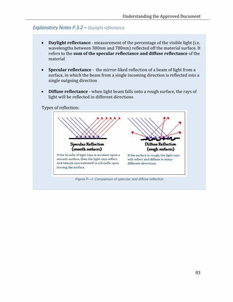
Understanding the Approved Document
83
Explanatory Notes P.3.2 – Daylight reflectance
Daylight reflectance - measurement of the percentage of the visible light (i.e.
wavelengths between 380nm and 780nm) reflected off the material surface. It refers to the sum of the specular reflectance and diffuse reflectance of the material
Specular reflectance - the mirror-liked reflection of a beam of light from a surface, in which the beam from a single incoming direction is reflected into a single outgoing direction
Diffuse reflectance - when light beam falls onto a rough surface, the rays of
light will be reflected in different directions
Types of reflection:
Figure P—I: Comparison of specular and diffuse reflection
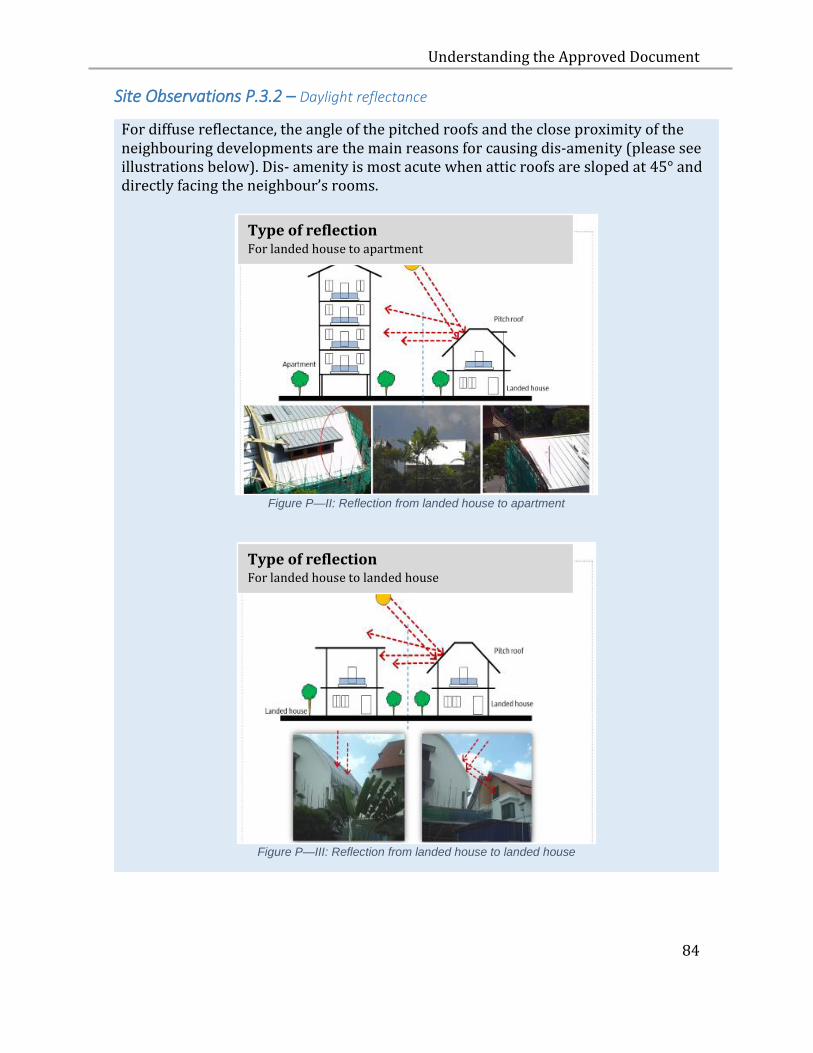
Understanding the Approved Document
84
Site Observations P.3.2 – Daylight reflectance
For diffuse reflectance, the angle of the pitched roofs and the close proximity of the neighbouring developments are the main reasons for causing dis-amenity (please see illustrations below). Dis- amenity is most acute when attic roofs are sloped at 45° and directly facing the neighbour’s rooms.
Figure P—II: Reflection from landed house to apartment
Figure P—III: Reflection from landed house to landed house
Type of reflection For landed house to apartment
Type of reflection For landed house to landed house
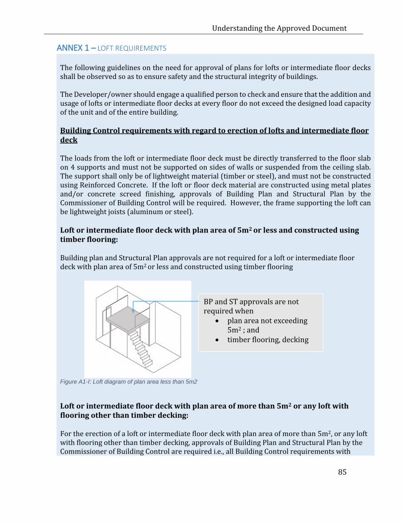
Understanding the Approved Document
85
ANNEX 1 – LOFT REQUIREMENTS The following guidelines on the need for approval of plans for lofts or intermediate floor decks shall be observed so as to ensure safety and the structural integrity of buildings. The Developer/owner should engage a qualified person to check and ensure that the addition and usage of lofts or intermediate floor decks at every floor do not exceed the designed load capacity of the unit and of the entire building. Building Control requirements with regard to erection of lofts and intermediate floor deck The loads from the loft or intermediate floor deck must be directly transferred to the floor slab on 4 supports and must not be supported on sides of walls or suspended from the ceiling slab. The support shall only be of lightweight material (timber or steel), and must not be constructed using Reinforced Concrete. If the loft or floor deck material are constructed using metal plates and/or concrete screed finishing, approvals of Building Plan and Structural Plan by the Commissioner of Building Control will be required. However, the frame supporting the loft can be lightweight joists (aluminum or steel). Loft or intermediate floor deck with plan area of 5m2 or less and constructed using timber flooring: Building plan and Structural Plan approvals are not required for a loft or intermediate floor deck with plan area of 5m2 or less and constructed using timber flooring
Figure A1-I: Loft diagram of plan area less than 5m2
Loft or intermediate floor deck with plan area of more than 5m2 or any loft with flooring other than timber decking: For the erection of a loft or intermediate floor deck with plan area of more than 5m2, or any loft with flooring other than timber decking, approvals of Building Plan and Structural Plan by the Commissioner of Building Control are required i.e., all Building Control requirements with
BP and ST approvals are not required when
plan area not exceeding 5m2 ; and
timber flooring, decking
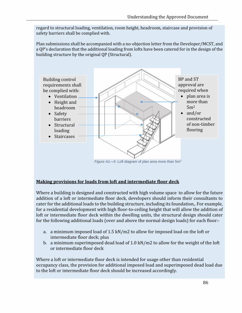
Understanding the Approved Document
86
regard to structural loading, ventilation, room height, headroom, staircase and provision of safety barriers shall be complied with. Plan submissions shall be accompanied with a no-objection letter from the Developer/MCST, and a QP’s declaration that the additional loading from lofts have been catered for in the design of the building structure by the original QP (Structural).
Figure A1—II: Loft diagram of plan area more than 5m2
Making provisions for loads from loft and intermediate floor deck Where a building is designed and constructed with high volume space to allow for the future addition of a loft or intermediate floor deck, developers should inform their consultants to cater for the additional loads to the building structure, including its foundation,. For example, for a residential development with high floor-to-ceiling height that will allow the addition of loft or intermediate floor deck within the dwelling units, the structural design should cater for the following additional loads (over and above the normal design loads) for each floor:-
a. a minimum imposed load of 1.5 kN/m2 to allow for imposed load on the loft or intermediate floor deck; plus
b. a minimum superimposed dead load of 1.0 kN/m2 to allow for the weight of the loft or intermediate floor deck
Where a loft or intermediate floor deck is intended for usage other than residential occupancy class, the provision for additional imposed load and superimposed dead load due to the loft or intermediate floor deck should be increased accordingly.
BP and ST approval are required when plan area is
more than 5m2
and/or constructed of non-timber flooring
Building control requirements shall be complied with:
Ventilation Height and
headroom Safety
barriers Structural
loading Staircases Staircase
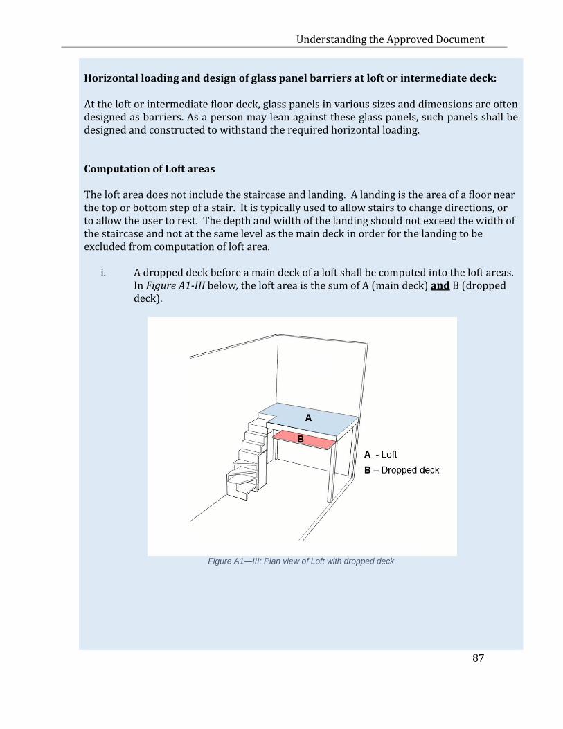
Understanding the Approved Document
87
Horizontal loading and design of glass panel barriers at loft or intermediate deck: At the loft or intermediate floor deck, glass panels in various sizes and dimensions are often designed as barriers. As a person may lean against these glass panels, such panels shall be designed and constructed to withstand the required horizontal loading. Computation of Loft areas The loft area does not include the staircase and landing. A landing is the area of a floor near the top or bottom step of a stair. It is typically used to allow stairs to change directions, or to allow the user to rest. The depth and width of the landing should not exceed the width of the staircase and not at the same level as the main deck in order for the landing to be excluded from computation of loft area.
i. A dropped deck before a main deck of a loft shall be computed into the loft areas. In Figure A1-III below, the loft area is the sum of A (main deck) and B (dropped deck).
Figure A1—III: Plan view of Loft with dropped deck

Understanding the Approved Document
88
ii. The landing space at the top of the flight of stairs will not be computed as part of the loft areas if the depth and width of this landing do not exceed the width of staircase. The landing shall not be at the same level as the main deck. In Figure A1-IV below, the loft area comprises A (main deck)but excludes C.
Figure A1-IV: Plan view of loft area with square landing
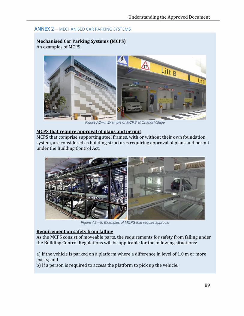
Understanding the Approved Document
89
ANNEX 2 – MECHANISED CAR PARKING SYSTEMS
Mechanised Car Parking Systems (MCPS) An examples of MCPS.
Figure A2—I: Example of MCPS at Changi Village
MCPS that require approval of plans and permit MCPS that comprise supporting steel frames, with or without their own foundation system, are considered as building structures requiring approval of plans and permit under the Building Control Act.
Figure A2—II: Examples of MCPS that require approval
Requirement on safety from falling As the MCPS consist of moveable parts, the requirements for safety from falling under the Building Control Regulations will be applicable for the following situations: a) If the vehicle is parked on a platform where a difference in level of 1.0 m or more exists; and b) If a person is required to access the platform to pick up the vehicle.
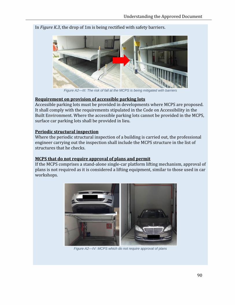
Understanding the Approved Document
90
In Figure K.3, the drop of 1m is being rectified with safety barriers.
Figure A2—III: The risk of fall at the MCPS is being mitigated with barriers
Requirement on provision of accessible parking lots Accessible parking lots must be provided in developments where MCPS are proposed. It shall comply with the requirements stipulated in the Code on Accessibility in the Built Environment. Where the accessible parking lots cannot be provided in the MCPS, surface car parking lots shall be provided in lieu. Periodic structural inspection Where the periodic structural inspection of a building is carried out, the professional engineer carrying out the inspection shall include the MCPS structure in the list of structures that he checks. MCPS that do not require approval of plans and permit If the MCPS comprises a stand-alone single-car platform lifting mechanism, approval of plans is not required as it is considered a lifting equipment, similar to those used in car workshops.
Figure A2—IV: MCPS which do not require approval of plans

Understanding the Approved Document
91
Requirement on car lifts which convey driver/passengers A MCPS is distinguished from a car lift in that a car lift is intended to convey vehicles together with driver and/or passengers during operation. Vehicle Lifts carry Vehicle with Human (driver or any passengers) are regarded as a lift, and must comply with
1. Code of Practice on the Installation, Operation & Maintenance of Electric Passenger and Goods Lifts – SS550 (for Building Plans submitted on and after 1 July 2010) or CP 2 (for Building Plans submitted on and after 1 Oct 2001).
2. Objectives and performance requirements set out in paragraph K of the Fifth
Schedule of the Building Control Regulations.
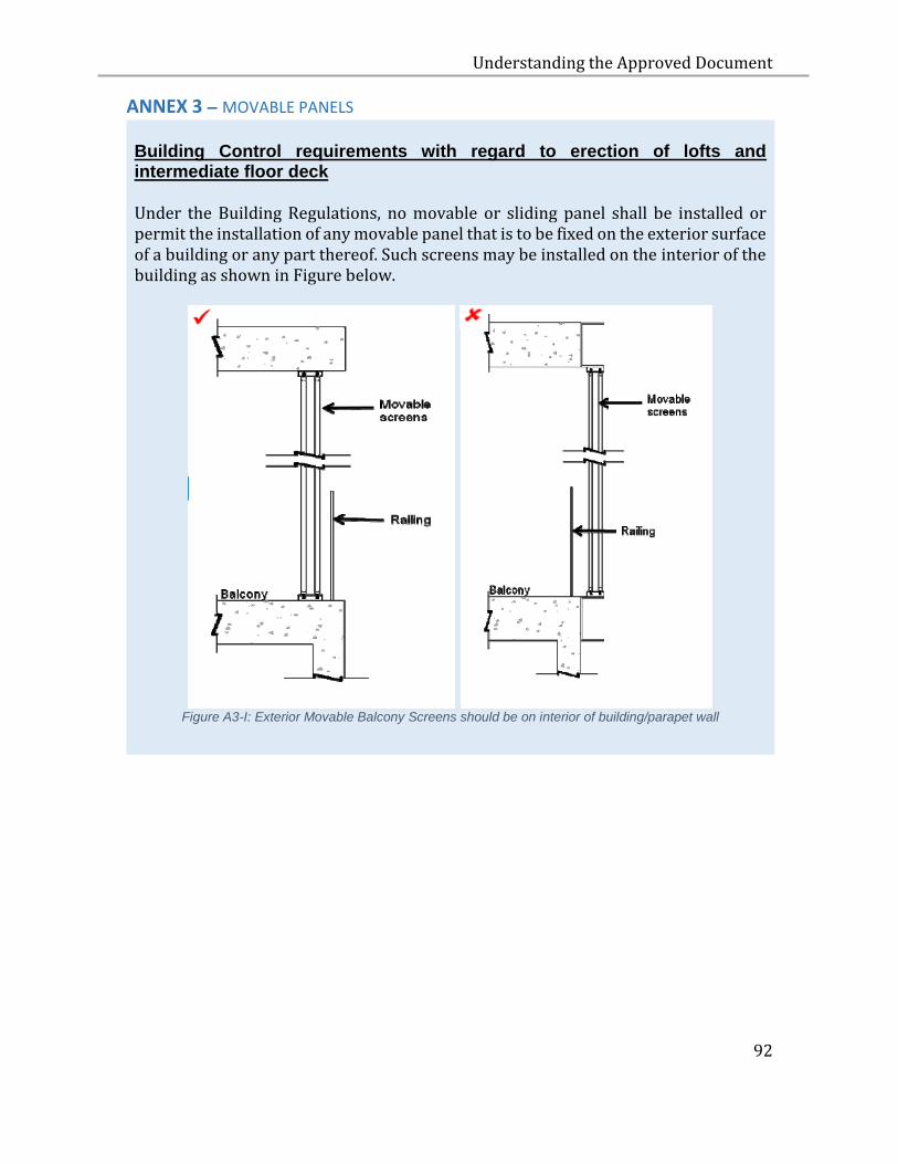
Understanding the Approved Document
92
ANNEX 3 – MOVABLE PANELS
Building Control requirements with regard to erection of lofts and intermediate floor deck Under the Building Regulations, no movable or sliding panel shall be installed or permit the installation of any movable panel that is to be fixed on the exterior surface of a building or any part thereof. Such screens may be installed on the interior of the building as shown in Figure below.
Figure A3-I: Exterior Movable Balcony Screens should be on interior of building/parapet wall
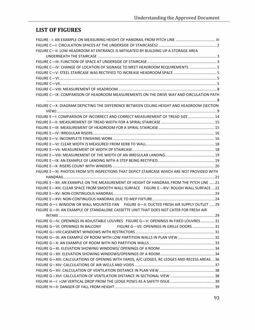
Understanding the Approved Document
93
LIST OF FIGURES
FIGURE - I: AN EXAMPLE ON MEASURING HEIGHT OF HANDRAIL FROM PITCH LINE ...................................... III FIGURE C—I: CIRCULATION SPACES AT THE UNDERSIDE OF STAIRCASES2 ....................................................... 2 FIGURE C—II: LOW HEADROOM AT ENTRANCE IS MITIGATED BY BUILDING UP A STORAGE AREA
UNDERNEATH THE STAIRCASE ................................................................................................................. 3 FIGURE C—III: FUNCTION OF SPACE AT UNDERSIDE OF STAIRCASE .................................................................. 3 FIGURE C—IV: CHANGE OF LOCATION OF SIGNAGE TO MEET HEADROOM REQUIREMENTS .......................... 5 FIGURE C—V: STEEL STAIRCASE WAS RECTIFIED TO INCREASE HEADROOM SPACE ......................................... 5 FIGURE C—VI ...................................................................................................................................................... 5 FIGURE C—VII ..................................................................................................................................................... 5 FIGURE C—VIII: MEASUREMENT OF HEADROOM ............................................................................................. 8 FIGURE C—IX: COMPARISON OF HEADROOM MEASUREMENTS ON THE DRIVE WAY AND CIRCULATION PATH
.................................................................................................................................................................. 8 FIGURE C—X: DIAGRAM DEPICTING THE DIFFERENCE BETWEEN CEILING HEIGHT AND HEADROOM (SECTION
VIEW) ........................................................................................................................................................ 9 FIGURE E—I: COMPARISON OF INCORRECT AND CORRECT MEASUREMENT OF TREAD SIZE ......................... 14 FIGURE E—II: MEASUREMENT OF TREAD WIDTH FOR A SPIRAL STAIRCASE ................................................... 15 FIGURE E—III: MEASUREMENT OF HEADROOM FOR A SPIRAL STAIRCASE ..................................................... 15 FIGURE E—IV: IRREGULAR RISERS .................................................................................................................... 16 FIGURE E—V: INCOMPLETE FINISHING WORK ................................................................................................. 16 FIGURE E—VI: CLEAR WIDTH IS MEASURED FROM KERB TO WALL ................................................................. 18 FIGURE E—VII: MEASUREMENT OF WIDTH OF STAIRCASE .............................................................................. 18 FIGURE E—VIII: MEASUREMENT OF THE WIDTH OF AN IRREGULAR LANDING ............................................... 19 FIGURE E—IX: AN EXAMPLE OF LANDING WITH A STEP BEING RECTIFIED ...................................................... 19 FIGURE E—X: RISERS COUNT WITH WINDERS ................................................................................................. 20 FIGURE E—XI: PHOTOS FROM SITE INSPECTIONS THAT DEPICT STAIRCASE WHICH ARE NOT PROVIDED WITH
HANDRAIL ............................................................................................................................................... 21 FIGURE E—XII: AN EXAMPLE ON THE MEASUREMENT OF HEIGHT OF HANDRAIL FROM THE PITCH LINE ..... 21 FIGURE E—XIII: CLEAR SPACE FROM SMOOTH WALL SURFACE FIGURE E—XIV: ROUGH WALL SURFACE ... 22 FIGURE E—XV: NON-CONTINUOUS HANDRAIL ................................................................................................ 24 FIGURE E—XVI: NON-CONTINUOUS HANDRAIL DUE TO MEP FIXTURE ........................................................... 24 FIGURE G—I: WINDOW OR WALL MOUNTED FAN FIGURE G—II: DUCTED FRESH AIR SUPPLY OUTLET ..... 29 FIGURE G—III: AN EXAMPLE OF STANDALONE CASSETTE UNIT THAT DOES NOT CATER FOR FRESH AIR
INTAKE .................................................................................................................................................... 29 FIGURE G—IV: OPENINGS IN ADJUSTABLE LOUVRES FIGURE G—V: OPENINGS IN FIXED LOUVRES ............. 31 FIGURE G—VI: OPENINGS IN BALCONY FIGURE G—VII: OPENINGS IN GRILLE DOORS ..................... 31 FIGURE G—VIII:CASEMENT WINDOWS WITH RESTRICTORS ........................................................................... 31 FIGURE G—IX: AN EXAMPLE OF ROOM WITH LOW PARTITION WALLS IN PLAN VIEW ................................... 32 FIGURE G—X: AN EXAMPLE OF ROOM WITH NO PARTITION WALLS .............................................................. 33 FIGURE G—XI: ELEVATION SHOWING WINDOWS/ OPENINGS OF A ROOM .................................................... 34 FIGURE G—XII: ELEVATION SHOWING WINDOWS/OPENINGS OF A ROOM.................................................... 34 FIGURE G—XIII: CALCULATIONS OF OPENING WITH YARDS, A/C LEDGES, RC LEDGES AND RECESS AREAS ... 36 FIGURE G—XIV: CALCULATIONS OF AIR WELLS AND VOIDS ............................................................................ 37 FIGURE G—XV: CALCULATION OF VENTILATION DISTANCE IN PLAN VIEW ..................................................... 38 FIGURE G—XVI: CALCULATION OF VENTILATION DISTANCE IN SECTIONAL VIEW .......................................... 38 FIGURE H—I: >1M VERTICAL DROP FROM THE LEDGE POSES AS A SAFETY ISSUE .......................................... 39 FIGURE H—II: DANGER OF FALL FROM HEIGHT ............................................................................................... 39
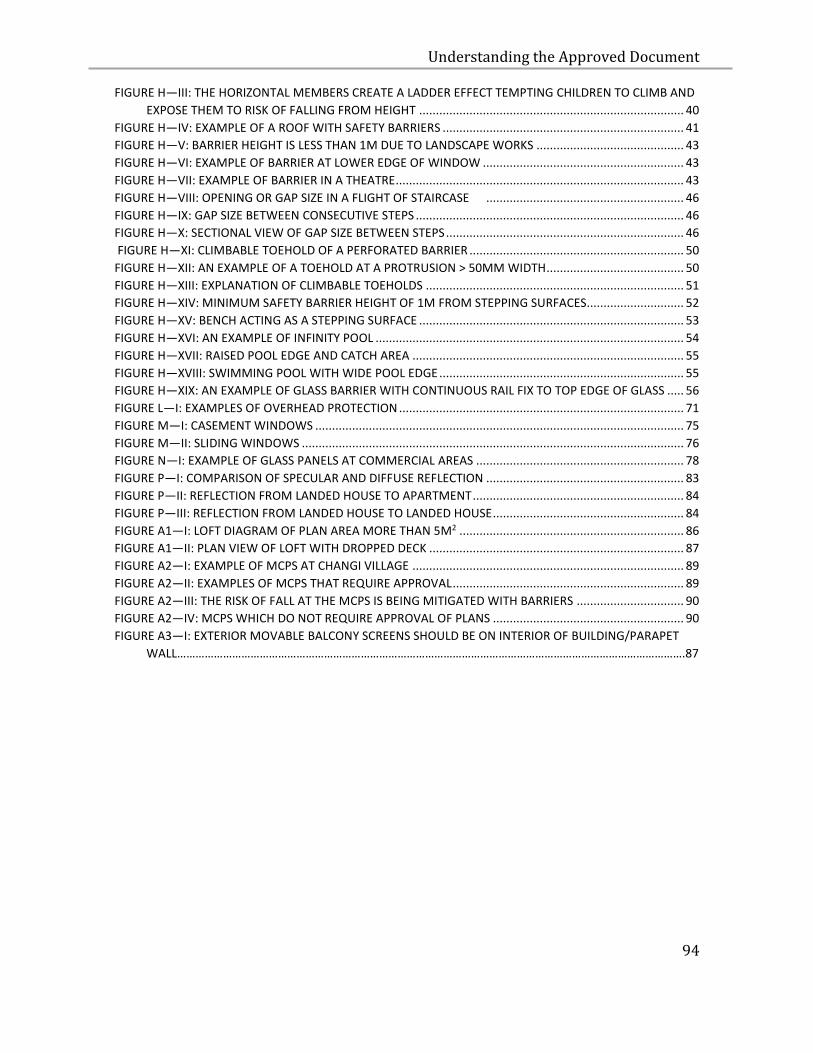
Understanding the Approved Document
94
FIGURE H—III: THE HORIZONTAL MEMBERS CREATE A LADDER EFFECT TEMPTING CHILDREN TO CLIMB AND
EXPOSE THEM TO RISK OF FALLING FROM HEIGHT ............................................................................... 40 FIGURE H—IV: EXAMPLE OF A ROOF WITH SAFETY BARRIERS ........................................................................ 41 FIGURE H—V: BARRIER HEIGHT IS LESS THAN 1M DUE TO LANDSCAPE WORKS ............................................ 43 FIGURE H—VI: EXAMPLE OF BARRIER AT LOWER EDGE OF WINDOW ............................................................ 43 FIGURE H—VII: EXAMPLE OF BARRIER IN A THEATRE ...................................................................................... 43 FIGURE H—VIII: OPENING OR GAP SIZE IN A FLIGHT OF STAIRCASE ........................................................... 46 FIGURE H—IX: GAP SIZE BETWEEN CONSECUTIVE STEPS ................................................................................ 46 FIGURE H—X: SECTIONAL VIEW OF GAP SIZE BETWEEN STEPS ....................................................................... 46 FIGURE H—XI: CLIMBABLE TOEHOLD OF A PERFORATED BARRIER ................................................................ 50 FIGURE H—XII: AN EXAMPLE OF A TOEHOLD AT A PROTRUSION > 50MM WIDTH ......................................... 50 FIGURE H—XIII: EXPLANATION OF CLIMBABLE TOEHOLDS ............................................................................. 51 FIGURE H—XIV: MINIMUM SAFETY BARRIER HEIGHT OF 1M FROM STEPPING SURFACES............................. 52 FIGURE H—XV: BENCH ACTING AS A STEPPING SURFACE ............................................................................... 53 FIGURE H—XVI: AN EXAMPLE OF INFINITY POOL ............................................................................................ 54 FIGURE H—XVII: RAISED POOL EDGE AND CATCH AREA ................................................................................. 55 FIGURE H—XVIII: SWIMMING POOL WITH WIDE POOL EDGE ......................................................................... 55 FIGURE H—XIX: AN EXAMPLE OF GLASS BARRIER WITH CONTINUOUS RAIL FIX TO TOP EDGE OF GLASS ..... 56 FIGURE L—I: EXAMPLES OF OVERHEAD PROTECTION ..................................................................................... 71 FIGURE M—I: CASEMENT WINDOWS .............................................................................................................. 75 FIGURE M—II: SLIDING WINDOWS .................................................................................................................. 76 FIGURE N—I: EXAMPLE OF GLASS PANELS AT COMMERCIAL AREAS .............................................................. 78 FIGURE P—I: COMPARISON OF SPECULAR AND DIFFUSE REFLECTION ........................................................... 83 FIGURE P—II: REFLECTION FROM LANDED HOUSE TO APARTMENT ............................................................... 84 FIGURE P—III: REFLECTION FROM LANDED HOUSE TO LANDED HOUSE ......................................................... 84 FIGURE A1—I: LOFT DIAGRAM OF PLAN AREA MORE THAN 5M2 ................................................................... 86 FIGURE A1—II: PLAN VIEW OF LOFT WITH DROPPED DECK ............................................................................ 87 FIGURE A2—I: EXAMPLE OF MCPS AT CHANGI VILLAGE ................................................................................. 89 FIGURE A2—II: EXAMPLES OF MCPS THAT REQUIRE APPROVAL ..................................................................... 89 FIGURE A2—III: THE RISK OF FALL AT THE MCPS IS BEING MITIGATED WITH BARRIERS ................................ 90 FIGURE A2—IV: MCPS WHICH DO NOT REQUIRE APPROVAL OF PLANS ......................................................... 90
FIGURE A3—I: EXTERIOR MOVABLE BALCONY SCREENS SHOULD BE ON INTERIOR OF BUILDING/PARAPET
WALL………………………………………………………………………………………………………………………………………………….87
Understanding the Approved Document
95
Building and Construction Authority
52 Jurong Gateway Road
#11-01, Singapore 608550
www.bca.gov.sg