Embed Size (px)
Citation preview
Understanding the Path to High- Efficiency Chemical Engines
Chris F. Edwards
Kwee
Yan Teh, Shannon Miller, Matthew Svrcek, Sankaran
Ramakrishnan, and Adam Simpson
Advanced Energy Systems Laboratory Department of Mechanical Engineering
Stanford University
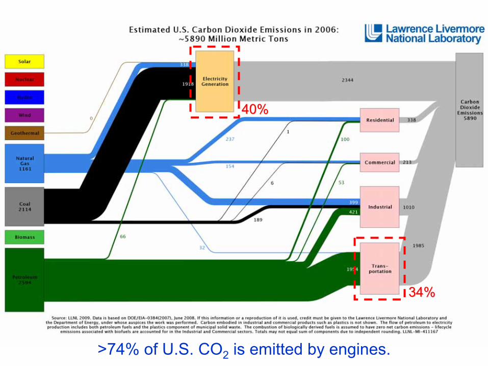
40%40%
34%34%
>74% of U.S. CO2
is emitted by engines.
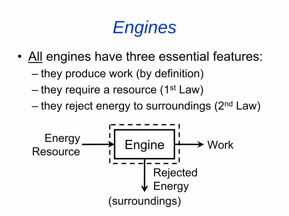
Engines•
All
engines have three essential features:
–
they produce work (by definition)–
they require a resource (1st
Law)
–
they reject energy to surroundings (2nd
Law)
Engine WorkEnergy Resource
Rejected Energy
(surroundings)
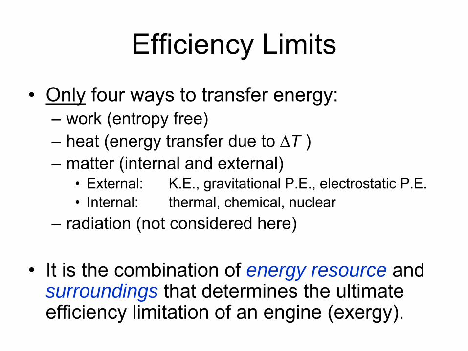
Efficiency Limits•
Only
four ways to transfer energy:
–
work (entropy free)–
heat (energy transfer due to ΔT )
–
matter (internal and external)•
External:
K.E., gravitational P.E., electrostatic P.E.
•
Internal: thermal, chemical, nuclear
–
radiation (not considered here)
•
It is the combination of energy resource and surroundings that determines the ultimate efficiency limitation of an engine (exergy).
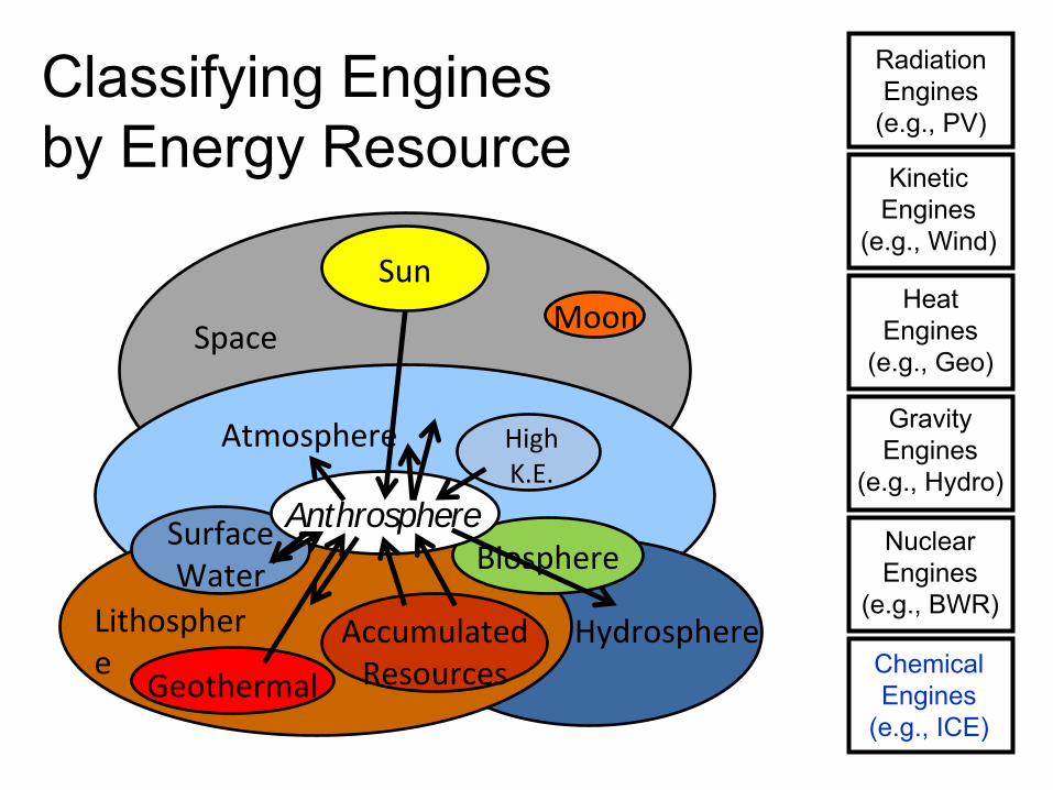
Classifying Engines by Energy Resource
Hydrosphere
Atmosphere
Lithospher
e
Space
Sun
AccumulatedResources
Surface
Water
Geothermal
Biosphere
HighK.E.
Moon
Anthrosphere
ChemicalEngines
(e.g., ICE)
NuclearEngines
(e.g., BWR)
HeatEngines
(e.g., Geo)
KineticEngines
(e.g., Wind)
RadiationEngines
(e.g., PV)
GravityEngines
(e.g., Hydro)
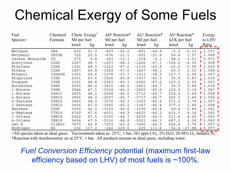
Chemical Exergy of Some FuelsFuel Chemical Chem. Exergy† ΔH° Reaction* ΔG° Reaction* ΔS° Reaction* Exergy Species+ Formula MJ per fuel MJ per fuel MJ per fuel kJ/K per fuel to LHV kmol kg kmol kg kmol kg kmol kg Ratio Methane CH4 832 51.9 -803 -50.0 -801 -49.9 -5.2 -0.33 1.037 Methanol CH3OH 722 22.5 -676 -21.1 -691 -21.6 50.4 1.57 1.068 Carbon Monoxide CO 275 9.8 -283 -10.1 -254 -9.1 -98.2 -3.51 0.971 Acetylene C2H2 1267 48.7 -1257 -48.3 -1226 -47.1 -104.6 -4.02 1.008 Ethylene C2H4 1361 48.5 -1323 -47.2 -1316 -46.9 -25.2 -0.90 1.029 Ethane C2H6 1497 49.8 -1429 -47.5 -1447 -48.1 60.5 2.01 1.048 Ethanol C2H5OH 1363 29.6 -1278 -27.7 -1313 -28.5 117.7 2.56 1.067 Propylene C3H6 2001 47.6 -1926 -45.8 -1937 -46.0 36.6 0.87 1.039 Propane C3H8 2151 48.8 -2043 -46.3 -2082 -47.2 129.2 2.93 1.053 Butadiene C4H6 2500 46.2 -2410 -44.5 -2421 -44.7 36.9 0.68 1.038 i-Butene C4H8 2644 47.1 -2524 -45.0 -2560 -45.6 120.2 2.14 1.047 i-Butane C4H10 2800 48.2 -2648 -45.6 -2712 -46.7 214.4 3.69 1.058 n-Butane C4H10 2805 48.3 -2657 -45.7 -2717 -46.7 200.0 3.44 1.056 n-Pentane C5H12 3460 48.0 -3272 -45.3 -3353 -46.5 271.3 3.76 1.057 i-Pentane C5H12 3454 47.9 -3265 -45.2 -3347 -46.4 277.0 3.84 1.058 Benzene C6H6 3299 42.2 -3169 -40.6 -3190 -40.8 69.4 0.89 1.041 n-Heptane C7H16 4769 47.6 -4501 -44.9 -4625 -46.2 415.0 4.14 1.060 i-Octane C8H18 5422 47.5 -5100 -44.7 -5259 -46.0 531.4 4.65 1.063 n-Octane C8H18 5424 47.5 -5116 -44.8 -5261 -46.1 487.1 4.26 1.060 Jet-A C12H23 7670 45.8 -7253 -43.4 -7440 -44.5 626.4 3.74 1.057 Hydrogen H2 236 117.2 -242 -120.0 -225 -111.6 -56.2 -27.88 0.977
+All species taken as ideal gases. †Environment taken as: 25°C, 1 bar, 363 ppm CO2, 2% H2O, 20.48% O2, balance N2 .*Reaction with stoichiometric air at 25°C, 1 bar. All products present as ideal gases, including water.
Fuel Conversion Efficiency potential (maximum first-law efficiency based on LHV) of most fuels is ~100%.
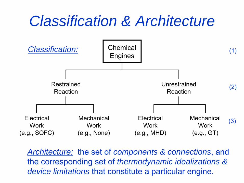
Classification & Architecture
Restrained
Reaction
Unrestrained
Reaction
ElectricalWork
(e.g., SOFC)
MechanicalWork
(e.g., None)
ElectricalWork
(e.g., MHD)
MechanicalWork
(e.g., GT)
Chemical
Engines
Architecture: the set of
components & connections, and the corresponding set of thermodynamic idealizations & device limitations that constitute a particular engine.
Classification: (1)
(2)
(3)
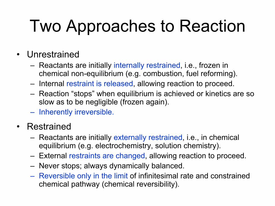
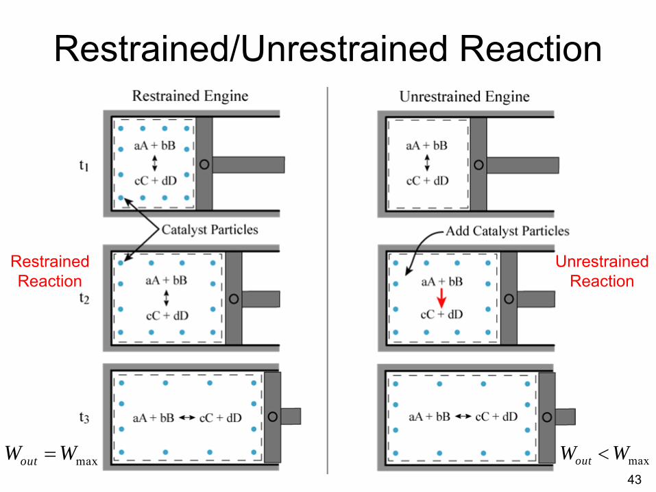
Two Approaches to Reaction•
Unrestrained–
Reactants are initially internally restrained, i.e., frozen in chemical non-equilibrium (e.g. combustion, fuel reforming).
–
Internal restraint is released, allowing reaction to proceed.–
Reaction “stops”
when equilibrium is achieved or kinetics are so slow as to be negligible (frozen again).
–
Inherently irreversible.
•
Restrained–
Reactants are initially externally restrained, i.e., in chemical equilibrium (e.g. electrochemistry, solution chemistry).
–
External restraints are changed, allowing reaction to proceed.–
Never stops; always dynamically balanced.–
Reversible only in the limit
of infinitesimal rate and constrained chemical pathway (chemical reversibility).
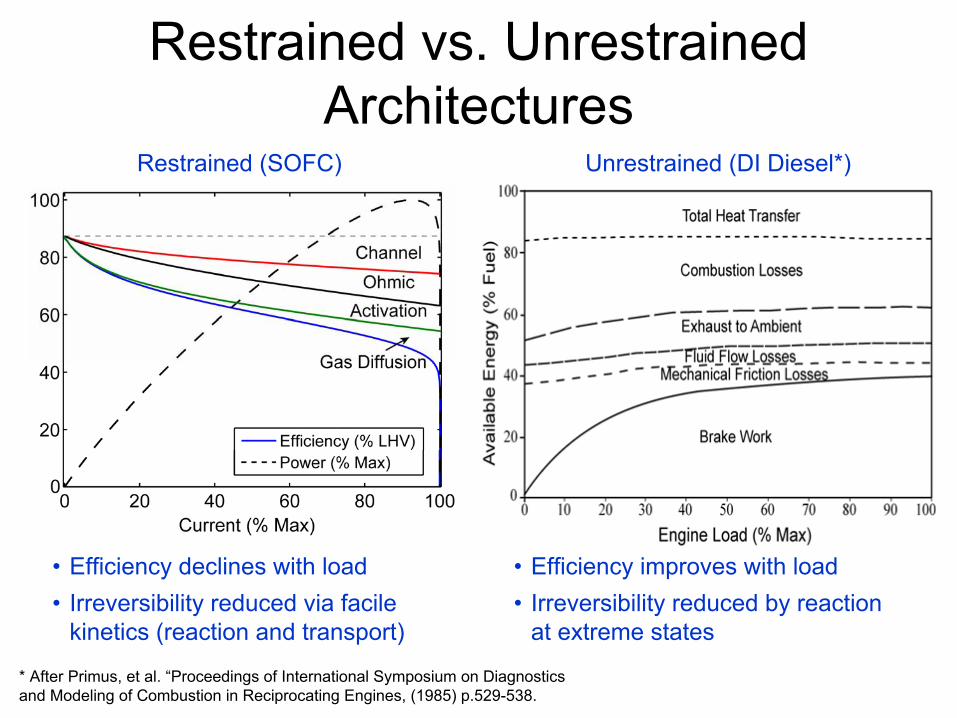
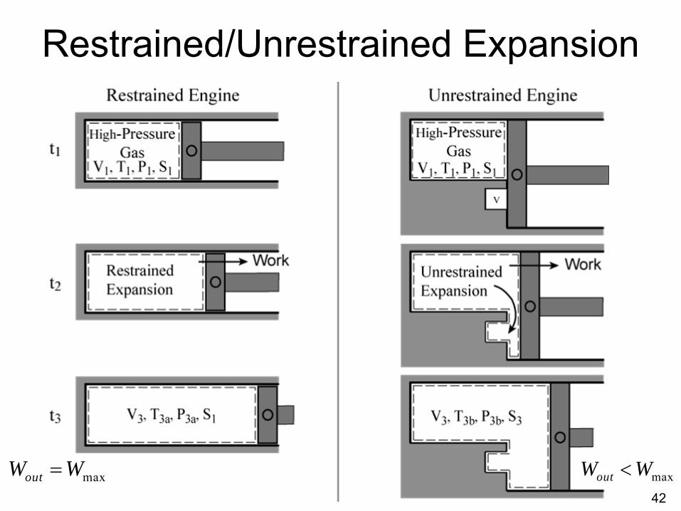
Restrained vs. Unrestrained Architectures
* After Primus, et al. “Proceedings of International Symposium on Diagnostics and Modeling of Combustion in Reciprocating Engines, (1985) p.529-538.
Restrained (SOFC) Unrestrained (DI Diesel*)
•
Efficiency declines with load•
Irreversibility reduced via facile kinetics (reaction and transport)
•
Efficiency improves with load•
Irreversibility reduced by reaction at extreme states
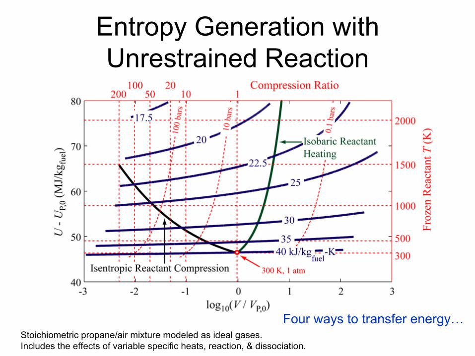
Entropy Generation with Unrestrained Reaction
Stoichiometric
propane/air mixture modeled as ideal gases. Includes the effects of variable specific heats, reaction, & dissociation.
Four ways to transfer energy…
100
101
1020
20
40
60
80
100
Compression Ratio
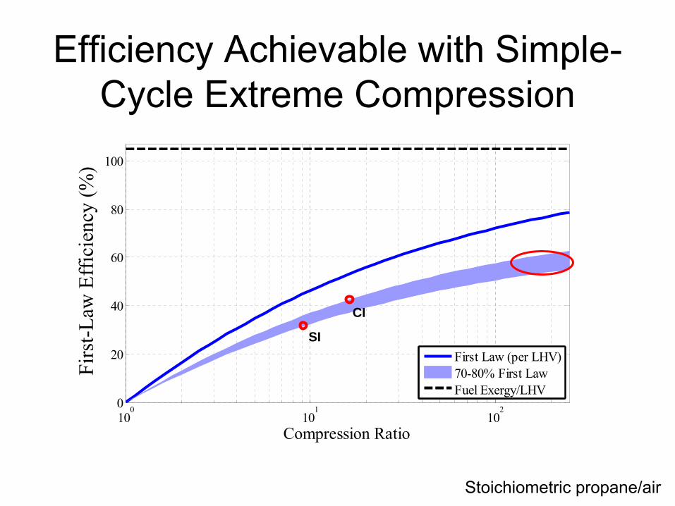
First Law (per LHV)70-80% First LawFuel Exergy/LHV
Efficiency Achievable with Simple- Cycle Extreme Compression
CI
SI
Stoichiometric
propane/air
Firs
t-Law
Eff
icie
ncy
(%)
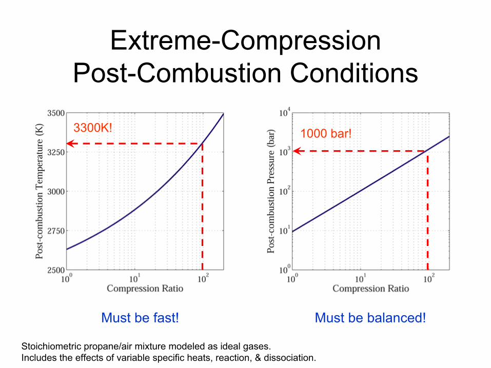
Extreme-Compression Post-Combustion Conditions
Stoichiometric
propane/air mixture modeled as ideal gases. Includes the effects of variable specific heats, reaction, & dissociation.
3300K! 1000 bar!
Must be fast! Must be balanced!
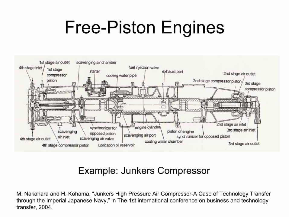
Free-Piston Engines
Example: Junkers Compressor
M. Nakahara and H. Kohama, “Junkers High Pressure Air Compressor-A Case of Technology Transfer through the Imperial Japanese Navy,”
in The 1st international conference on business and technology transfer, 2004.
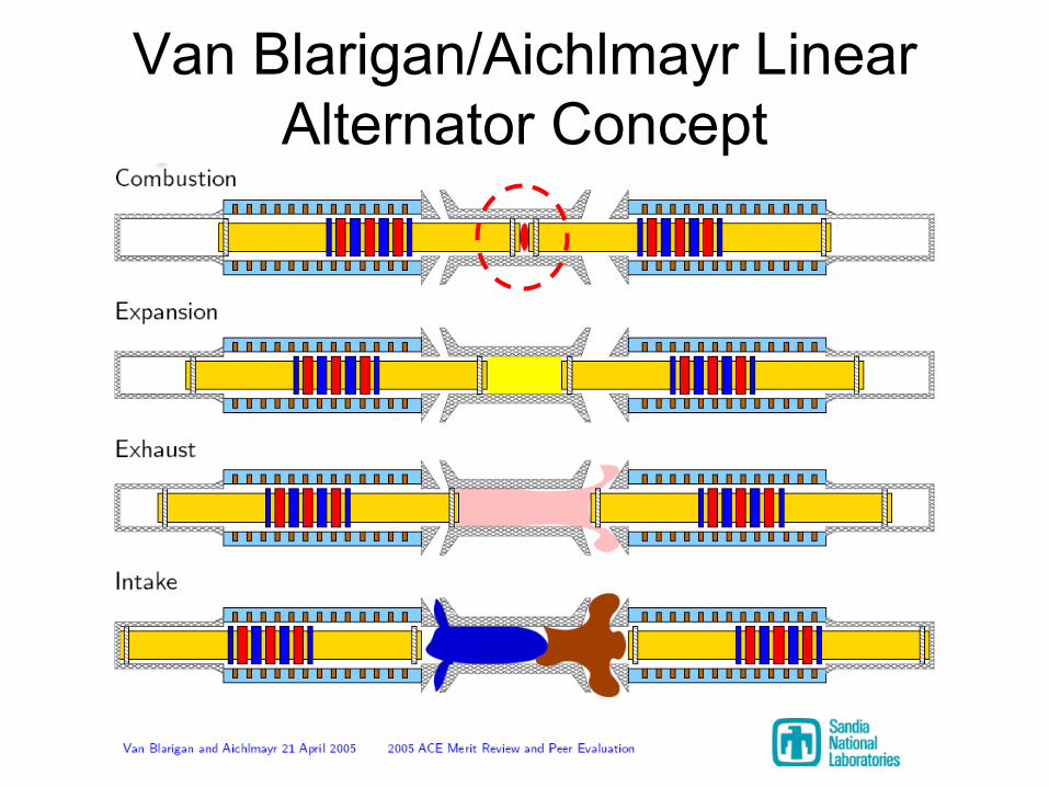
Van Blarigan/Aichlmayr
Linear Alternator Concept
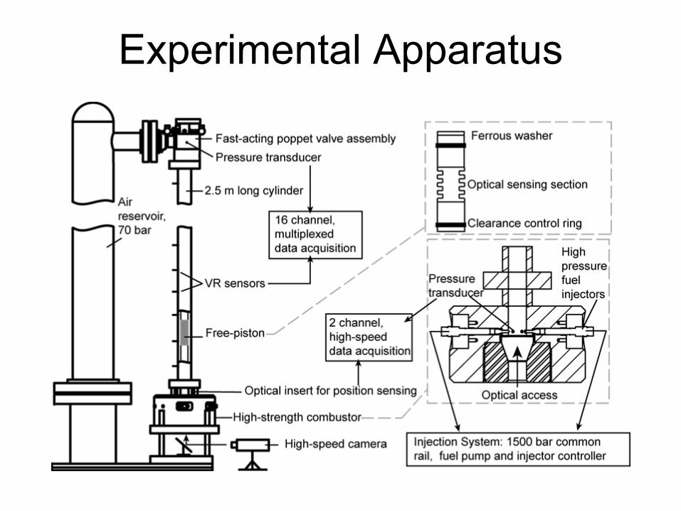
Experimental Apparatus
16
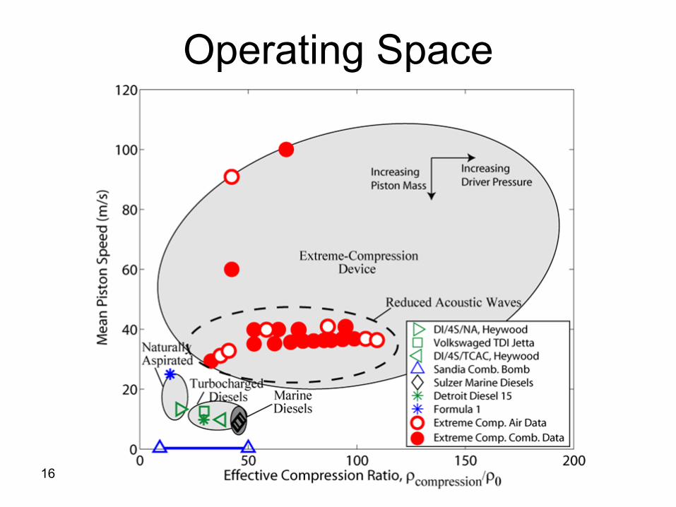
Operating Space
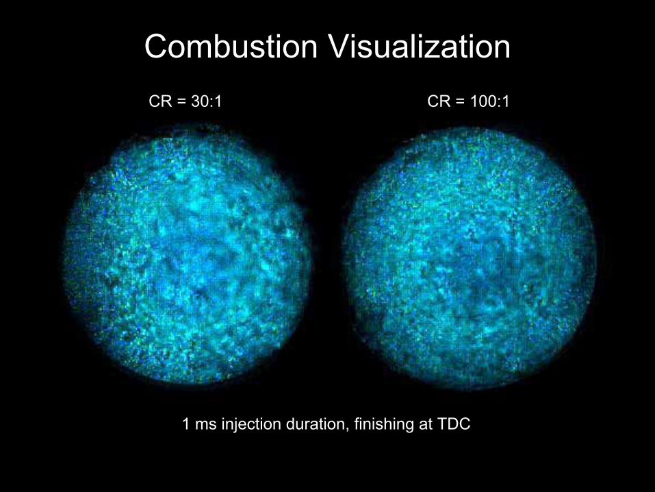
Combustion VisualizationCR = 30:1 CR = 100:1
1 ms injection duration, finishing at TDC
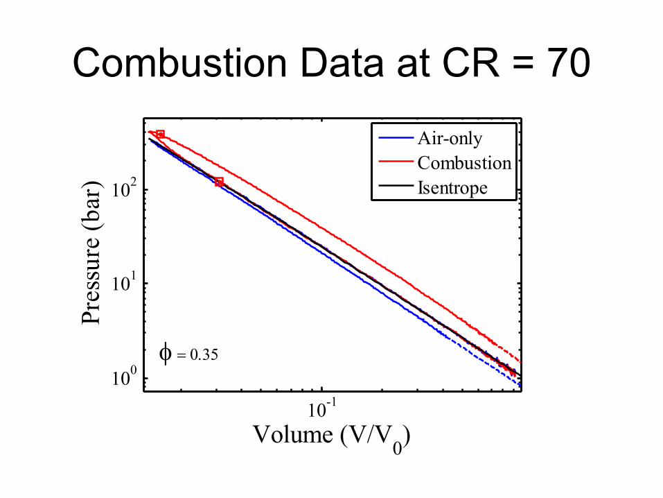
Combustion Data at CR = 70
10-1100
101
102
Volume (V/V0)
Pres
sure
(bar
)
Air-onlyCombustionIsentrope
φ
= 0.35
19
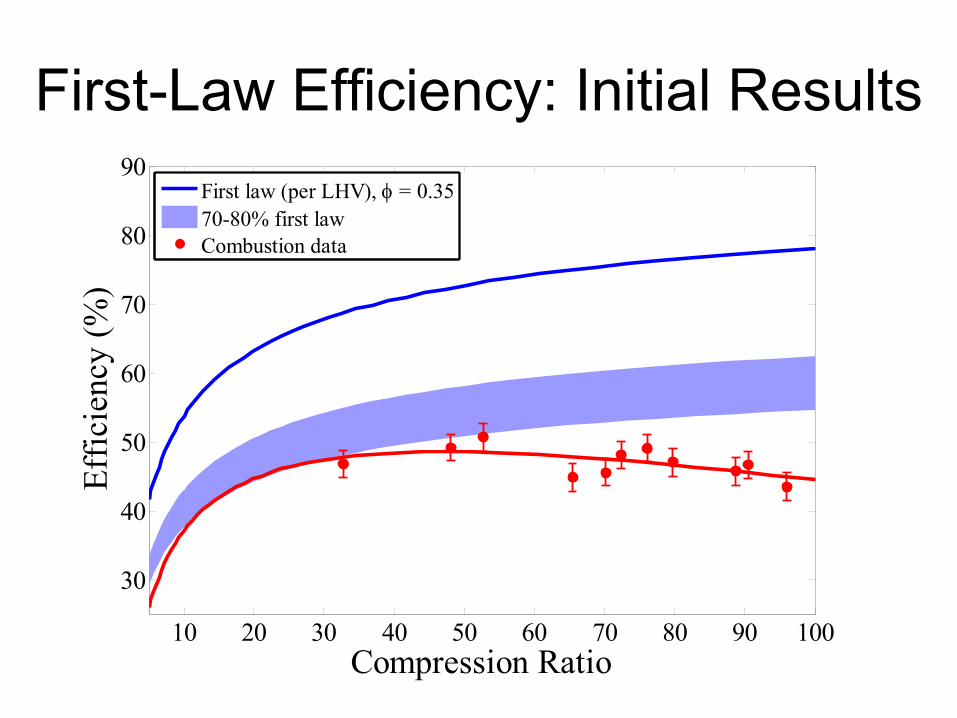
First-Law Efficiency: Initial Results
10 20 30 40 50 60 70 80 90 100
30
40
50
60
70
80
90
Compression Ratio
Effic
ienc
y (%
)
First law (per LHV), φ = 0.3570-80% first lawCombustion data
20
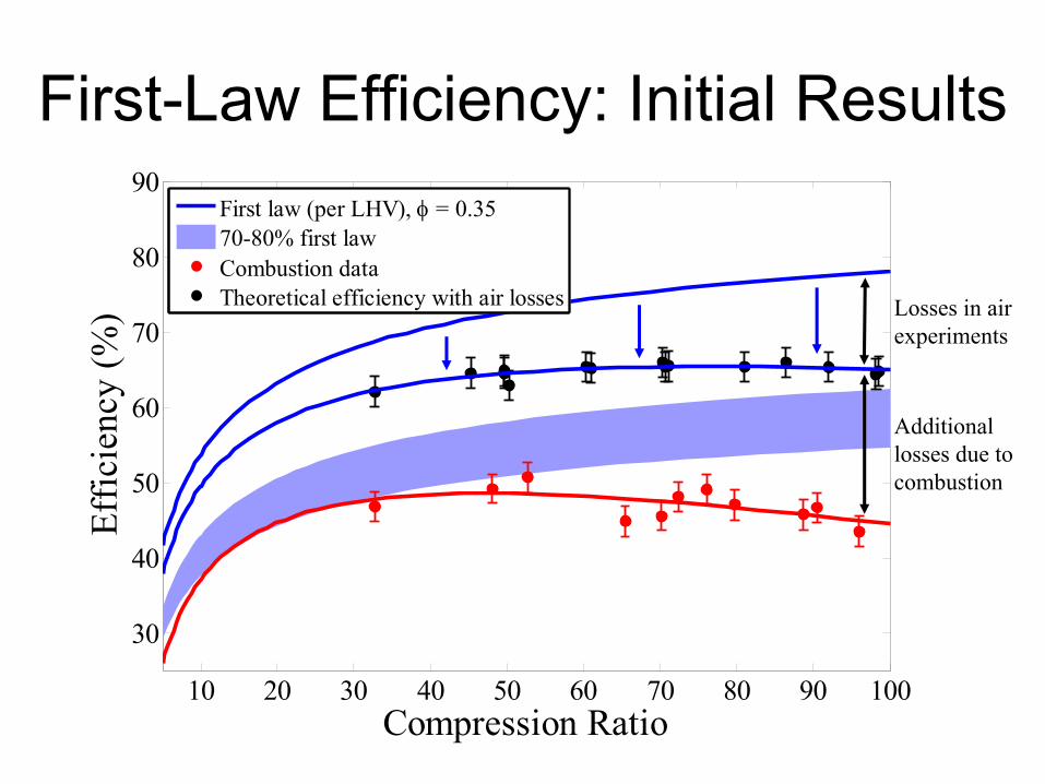
First-Law Efficiency: Initial Results
10 20 30 40 50 60 70 80 90 100
30
40
50
60
70
80
90
Compression Ratio
Effic
ienc
y (%
)
First law (per LHV), φ = 0.3570-80% first lawCombustion dataTheoretical efficiency with air losses Losses in air
experiments
Additionallosses due tocombustion
21
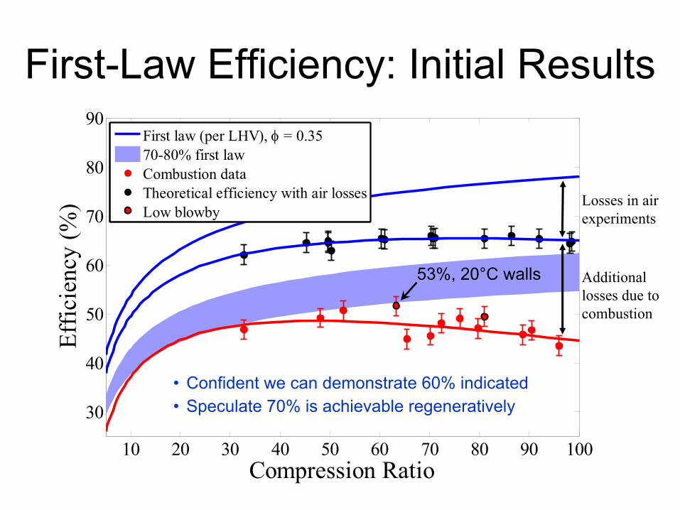
First-Law Efficiency: Initial Results
10 20 30 40 50 60 70 80 90 100
30
40
50
60
70
80
90
Compression Ratio
Effic
ienc
y (%
)
First law (per LHV), φ = 0.3570-80% first lawCombustion dataTheoretical efficiency with air lossesLow blowby
53%, 20°C walls
Losses in airexperiments
Additionallosses due tocombustion
•
Confident we can demonstrate 60% indicated•
Speculate 70% is achievable regeneratively
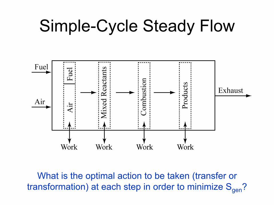
Simple-Cycle Steady Flow
What is the optimal action to be taken (transfer or transformation) at each step in order to minimize Sgen
?
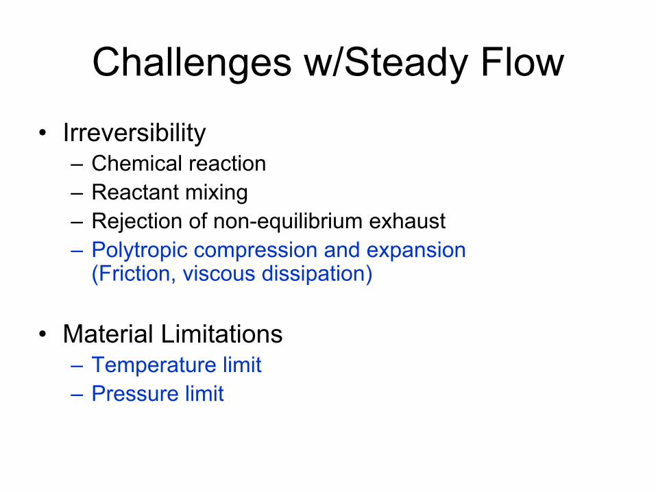
Challenges w/Steady Flow•
Irreversibility–
Chemical reaction
–
Reactant mixing–
Rejection of non-equilibrium exhaust
–
Polytropic
compression and expansion (Friction, viscous dissipation)
•
Material Limitations–
Temperature limit
–
Pressure limit
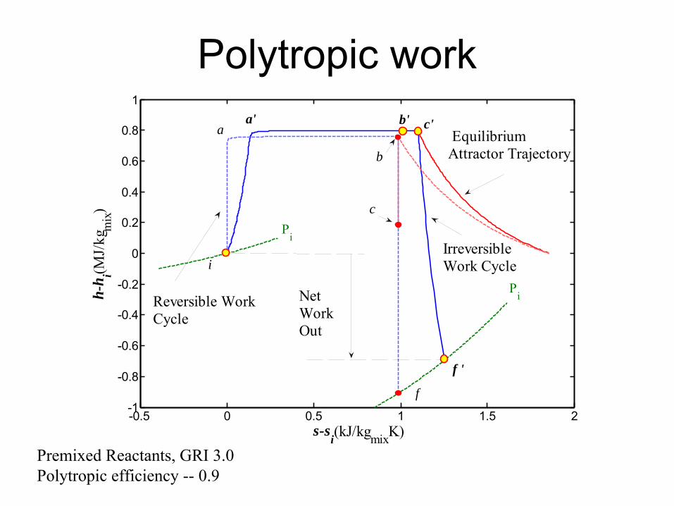
Polytropic
work
-0.5 0 0.5 1 1.5 2-1
-0.8
-0.6
-0.4
-0.2
0
0.2
0.4
0.6
0.8
1
s-si(kJ/kgmixK)
h-h i(M
J/kg
mix
)
i
b' c'
b
c
f '
f
Pi
a'a
Reversible WorkCycle
Net WorkOut
Equilibrium Attractor Trajectory
Irreversible Work Cycle
Pi
Premixed Reactants, GRI 3.0Polytropic
efficiency --
0.9
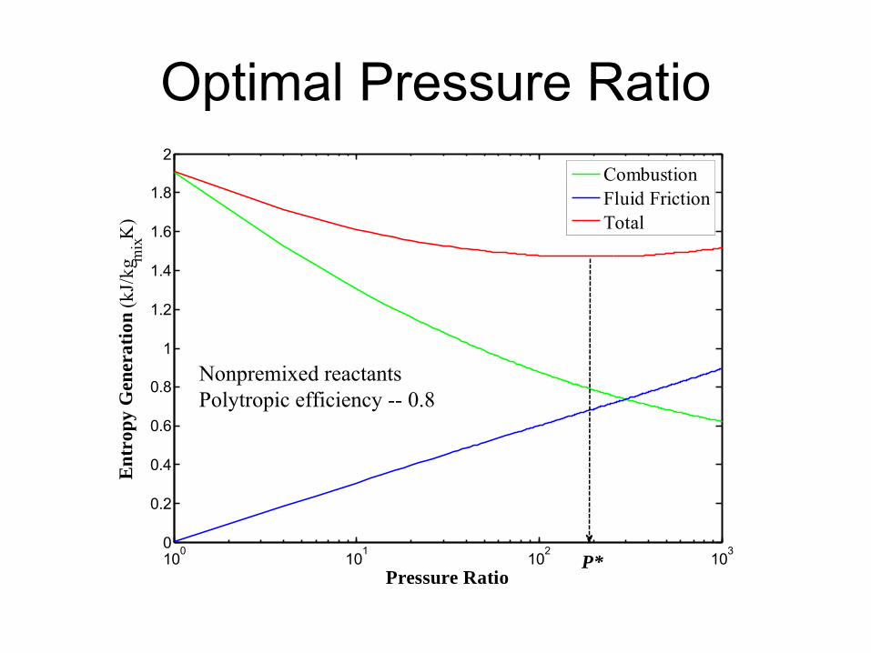
Optimal Pressure Ratio
100 101 102 1030
0.2
0.4
0.6
0.8
1
1.2
1.4
1.6
1.8
2
Pressure Ratio
Ent
ropy
Gen
erat
ion
(kJ/
kgm
ixK
)
CombustionFluid FrictionTotal
P*
Nonpremixed
reactantsPolytropic
efficiency --
0.8
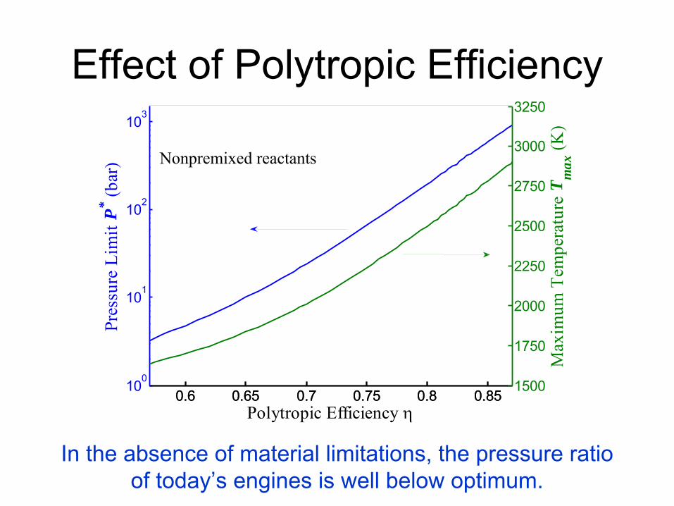
Effect of Polytropic
Efficiency
Polytropic Efficiency η
Pres
sure
Lim
it P* (b
ar)
0.6 0.65 0.7 0.75 0.8 0.85100
101
102
103
0.6 0.65 0.7 0.75 0.8 0.851500
1750
2000
2250
2500
2750
3000
3250
Max
imum
Tem
pera
ture
Tm
ax (K
)
Nonpremixed
reactants
In the absence of material limitations, the pressure ratio of today’s engines is well below optimum.
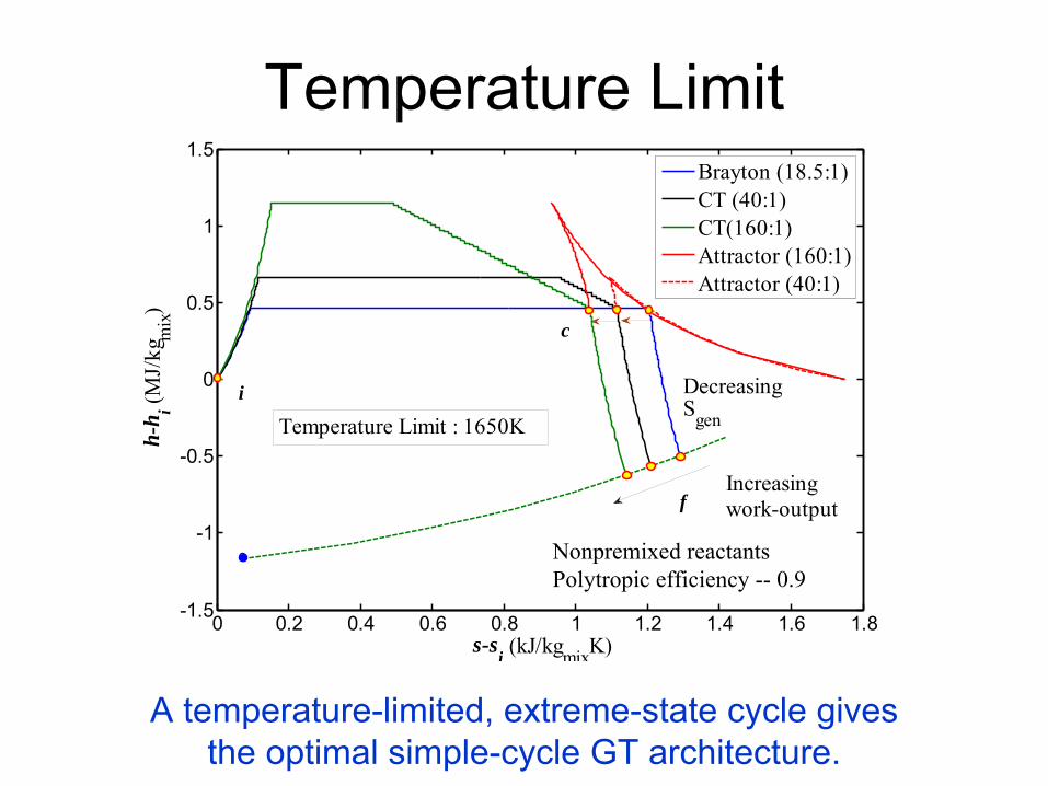
Temperature Limit
0 0.2 0.4 0.6 0.8 1 1.2 1.4 1.6 1.8-1.5
-1
-0.5
0
0.5
1
1.5
s-si (kJ/kgmixK)
h-h
i (MJ/
kgm
ix)
Brayton (18.5:1)CT (40:1)CT(160:1)Attractor (160:1)Attractor (40:1)
f
c
i
Increasingwork-output
DecreasingSgenTemperature Limit : 1650K
A temperature-limited, extreme-state cycle gives the optimal simple-cycle GT architecture.
Nonpremixed
reactants Polytropic
efficiency --
0.9
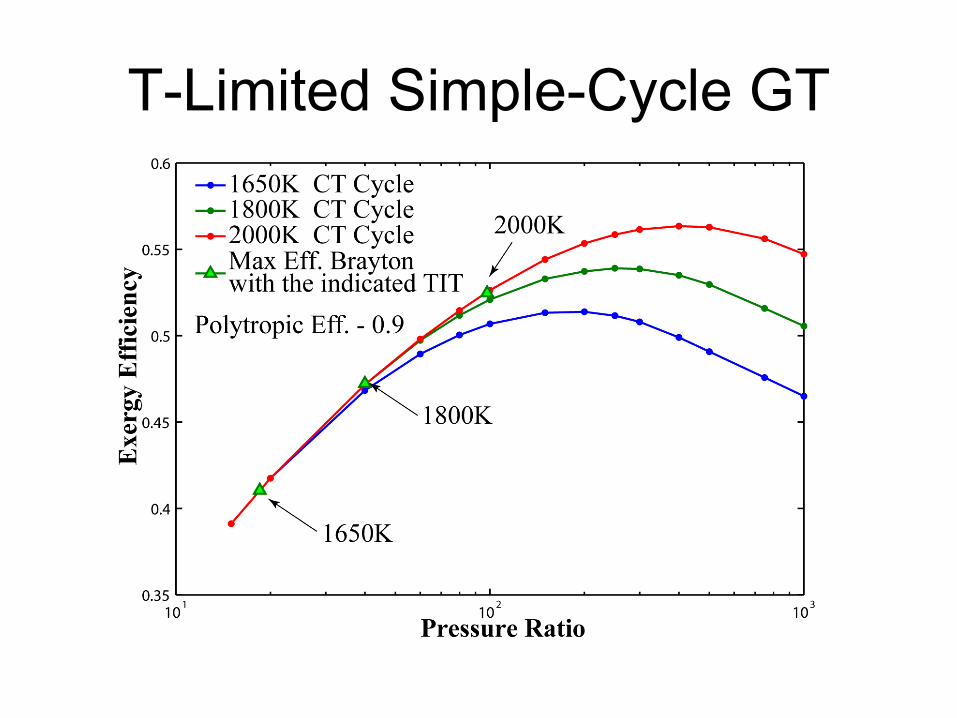
T-Limited Simple-Cycle GT
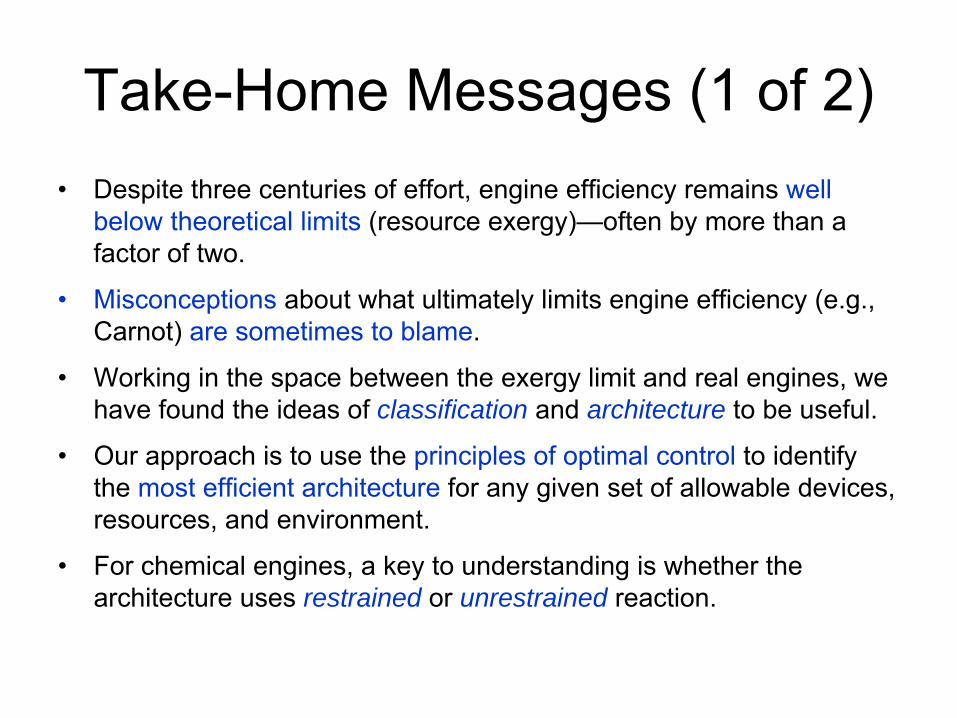
Take-Home Messages (1 of 2)•
Despite three centuries of effort, engine efficiency remains well below theoretical limits
(resource exergy)—often by more than a factor of two.
•
Misconceptions
about what ultimately limits engine efficiency (e.g., Carnot) are sometimes to blame.
•
Working in the space between the exergy limit and real engines, we have found the ideas of classification and
architecture to be useful.
•
Our approach is to use the principles of optimal control
to identify the most efficient architecture
for any given set of allowable devices, resources, and environment.
•
For chemical engines, a key to understanding is whether the architecture uses restrained or
unrestrained reaction.
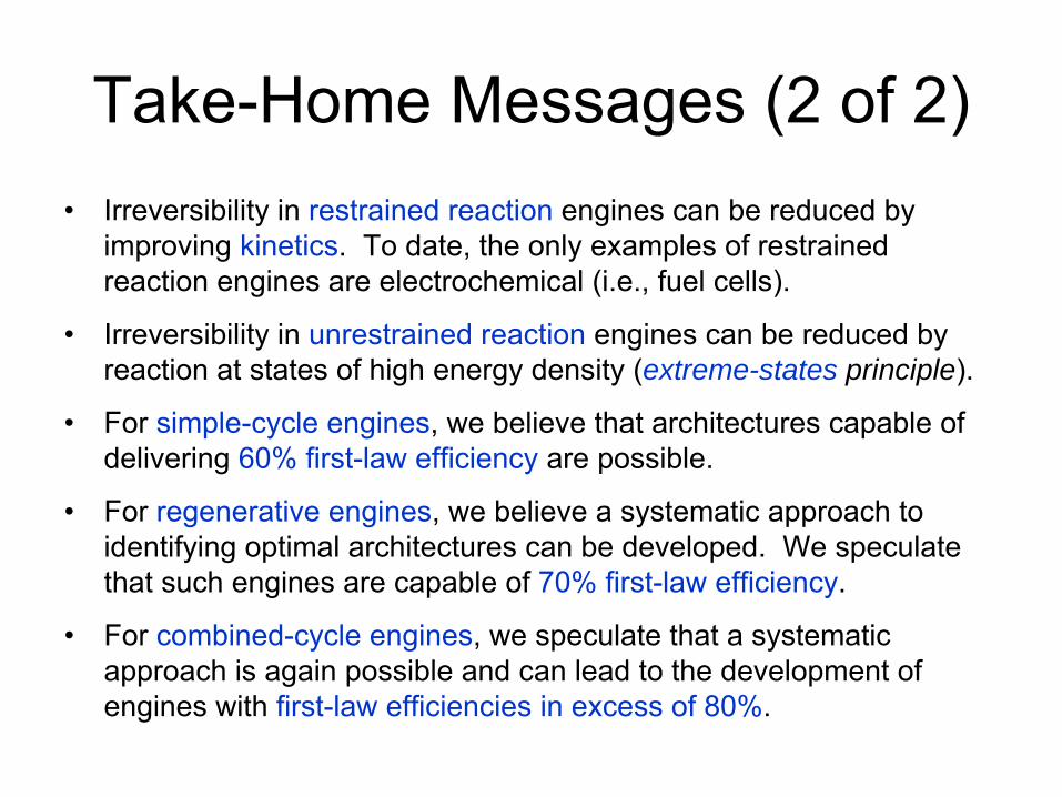
Take-Home Messages (2 of 2)•
Irreversibility in restrained reaction
engines can be reduced by improving kinetics. To date, the only examples of restrained reaction engines are electrochemical (i.e., fuel cells).
•
Irreversibility in unrestrained reaction
engines can be reduced by reaction at states of high energy density (extreme-states principle).
•
For simple-cycle engines, we believe that architectures capable of delivering 60% first-law efficiency
are possible.
•
For regenerative engines, we believe a systematic approach to identifying optimal architectures can be developed. We speculate that such engines are capable of 70% first-law efficiency.
•
For combined-cycle engines, we speculate that a systematic approach is again possible and can lead to the development of engines with first-law efficiencies in excess of 80%.

0.1
1.0
10.0
100.0
1600 1700 1800 1900 2000 2100Time (Years A.D.)
Firs
t-Law
Effi
cien
cy (%
) .
Savery, Newcomen (<0.5%)Watt/Boulton Steam EnginesPost-Watt Steam EnginesLenoir, Hugon Coal-Gas EnginesOtto/Langen Coal-Gas EnginesAtkinson, Tangye Coal-Gas EnginesBanki Spirits EnginePriestman's Oil EngineDiesel's Oil EnginesAutomotive SI EnginesTruck Diesel EnginesLarge Bore DI DieselsSteam TurbinesGas Turbine/Steam TurbinePolymer Electrolyte Membrane FCPhosphoric Acid Fuel CellsSOFC/Gas Turbine
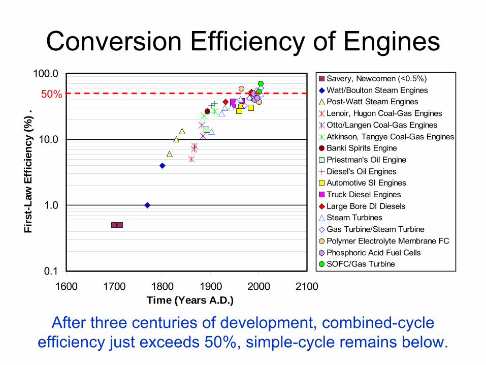
Conversion Efficiency of Engines
50%
After three centuries of development, combined-cycle efficiency just exceeds 50%, simple-cycle remains below.
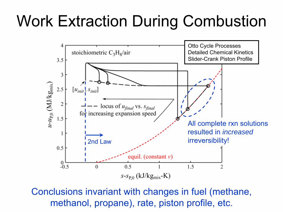
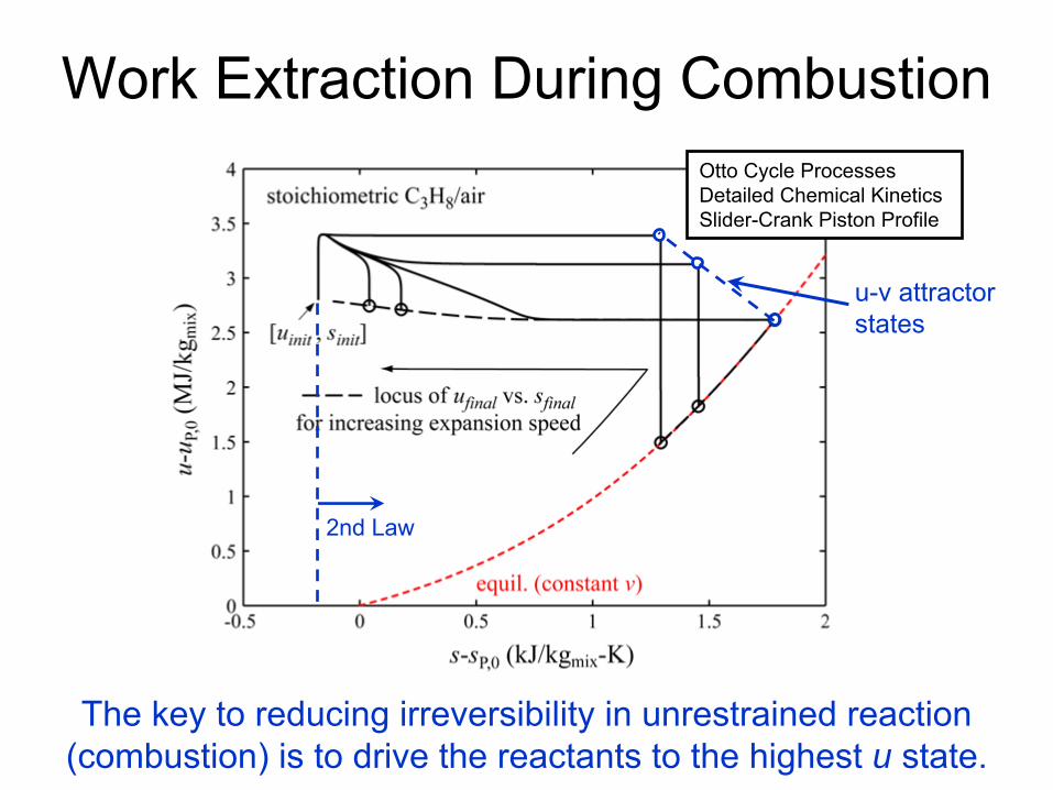
Work Extraction During CombustionOtto Cycle Processes
Detailed Chemical Kinetics Slider-Crank Piston Profile
All complete rxn solutions resulted in increased irreversibility!2nd Law
Conclusions invariant with changes in fuel (methane, methanol, propane), rate, piston profile, etc.
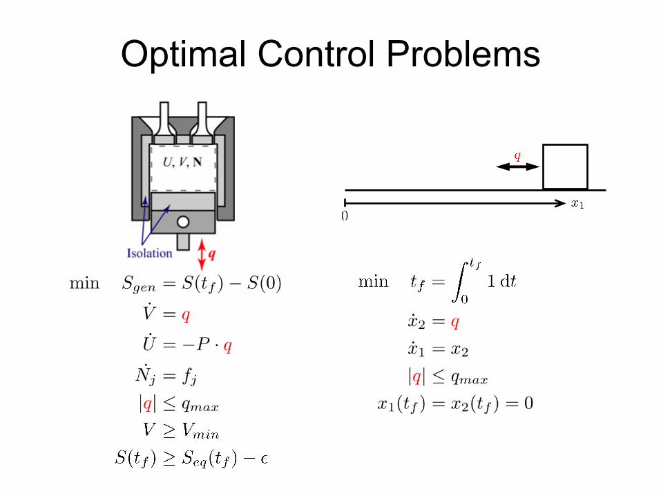
Optimal Control Problems
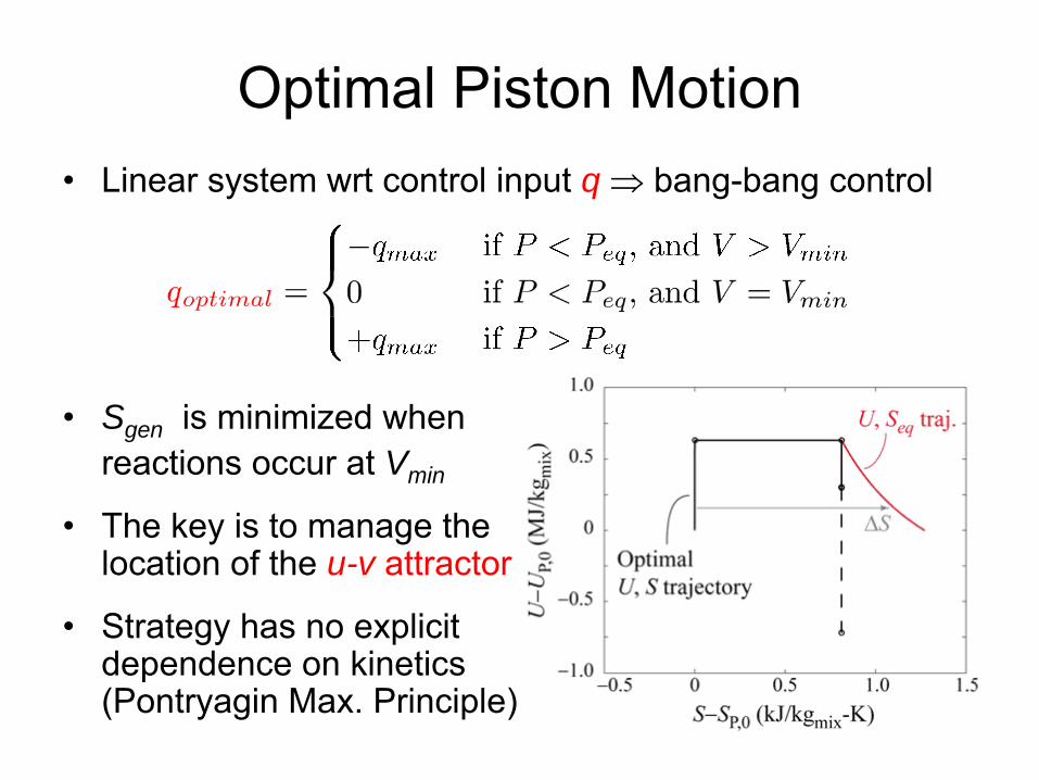
•
Linear system wrt
control input q ⇒ bang-bang control
•
Sgen is minimized when reactions occur at Vmin
•
The key is to manage the location of the u-v attractor
•
Strategy has no explicit dependence on kinetics
(Pontryagin
Max. Principle)
Optimal Piston Motion
Work Extraction During CombustionOtto Cycle Processes
Detailed Chemical Kinetics Slider-Crank Piston Profile
2nd Law
The key to reducing irreversibility in unrestrained reaction (combustion) is to drive the reactants to the highest u state.
u-v attractorstates
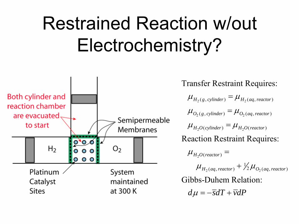
Restrained Reaction w/out Electrochemistry?
2 2
2 2
2 2
2
2 2
( , ) ( , )
( , ) ( , )
( ) ( )
( )
12( , ) ( , )
Transfer Restraint Requires:
Reaction Restraint Requires:
Gib
H g cylinder H aq reactor
O g cylinder O aq reactor
H O cylinder H O reactor
H O reactor
H aq reactor O aq reactor
μ μ
μ μ
μ μ
μ
μ μ
=
=
=
=
+
bs-Duhem Relation:d sdT vdPμ = − +
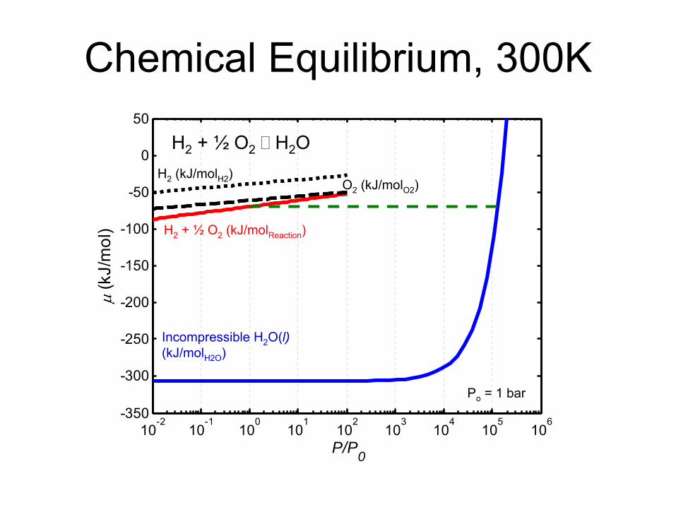
10-2
10-1
100
101
102
103
104
105
106
-350
-300
-250
-200
-150
-100
-50
0
50
P/P0
μ (k
J/m
ol)
Chemical Equilibrium, 300K
H2
(kJ/molH2
)O2
(kJ/molO2
)
H2
+ ½
O2
(kJ/molReaction
)
Incompressible H2
O(l)(kJ/molH2O
)
H2
+ ½
O2 H2O
Po
= 1 bar
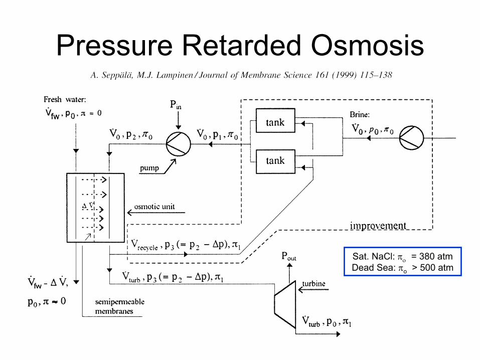
Pressure Retarded Osmosis
Sat. NaCl: πο
= 380 atm Dead Sea: πo
> 500 atm
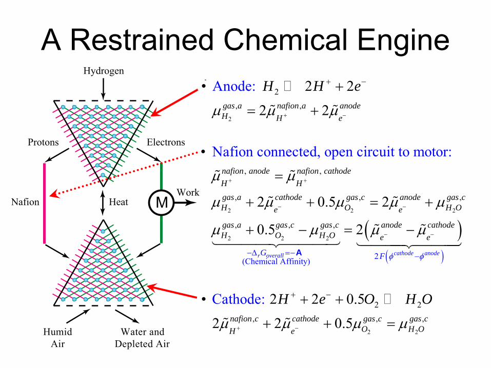
A Restrained Chemical Engine
Heat
HumidAir
Water and�Depleted Air
NafionWork
Protons Electrons
Hydrogen
M
2
2, ,
• 2 2
2
Anode:
2gas a nafion a anodeH H e
H H e
μ μ μ+ −
+ −+
= +% %
2 2
2 2, , ,
• 2 2 0.5
2 2 0.5
Cathode: nafion c cathode gas c gas c
O H OH e
H e O H O
μ μ μ μ+ −
+ −+ +
+ + =% %
2 2 2
2 2 2
(
, ,
, , ,
, ,
Chemical Affinity)
,
•
2 0
Nafion connected, open circuit to motor:
.5 2
0.5r overall
nafion anode nafion cathodeH Hgas a cathode gas c anode gas cH O H Oe e
gas a gas c gas cH O O
G
H
μ μ
μ μ μ μ μ
μ μ
+ +
− −
−Δ =−
=
+ + = +
+ −
% %
% %
14442A
( )( )2
2cathode anode
anode cathodee e
F φ φ
μ μ− −
−
= −% %4443 144424443
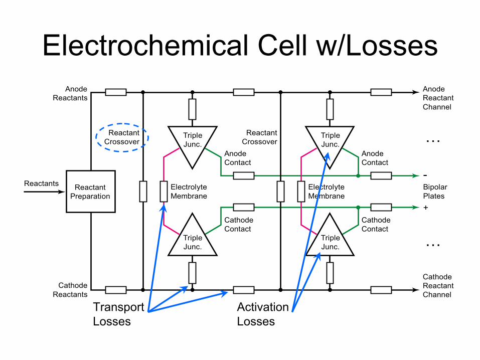
Electrochemical Cell w/Losses
ReactantPreparation
TripleJunc.
TripleJunc.
TripleJunc.
TripleJunc.
CathodeReactants
ReactantCrossover
ElectrolyteMembrane
AnodeContact
CathodeContact
Reactants
AnodeContact
CathodeContact
BipolarPlates
-
+
ElectrolyteMembrane
ReactantCrossover
AnodeReactants
CathodeReactantChannel
AnodeReactantChannel
TransportLosses
…
…
ActivationLosses
42
Restrained/Unrestrained Expansion
maxoutW W= maxoutW W<
43
Restrained/Unrestrained Reaction
maxoutW W= maxoutW W<
RestrainedReaction
UnrestrainedReaction
44
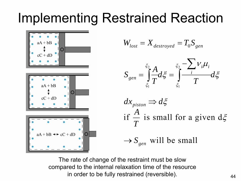
Implementing Restrained Reaction
2 2
1 1
0
if is small for a given d
will be small
lost destroyed gen
i ii
gen
piston
gen
W X T S
AS d dT T
dx dAT
S
ξ ξ
ξ ξ
ν μξ ξ
ξ
ξ
= =
−= =
⇒
→
∑∫ ∫
The rate of change of the restraint must be slow compared to the internal relaxation time of the resource
in order to be fully restrained (reversible).
45
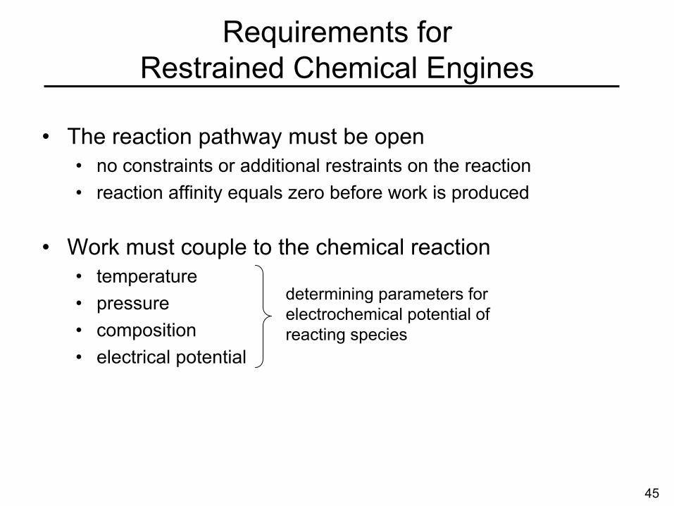
•
The reaction pathway must be open•
no constraints or additional restraints on the reaction•
reaction affinity equals zero before work is produced
•
Work must couple to the chemical reaction•
temperature•
pressure•
composition•
electrical potential
Requirements for Restrained Chemical Engines
determining parameters for electrochemical potential of reacting species

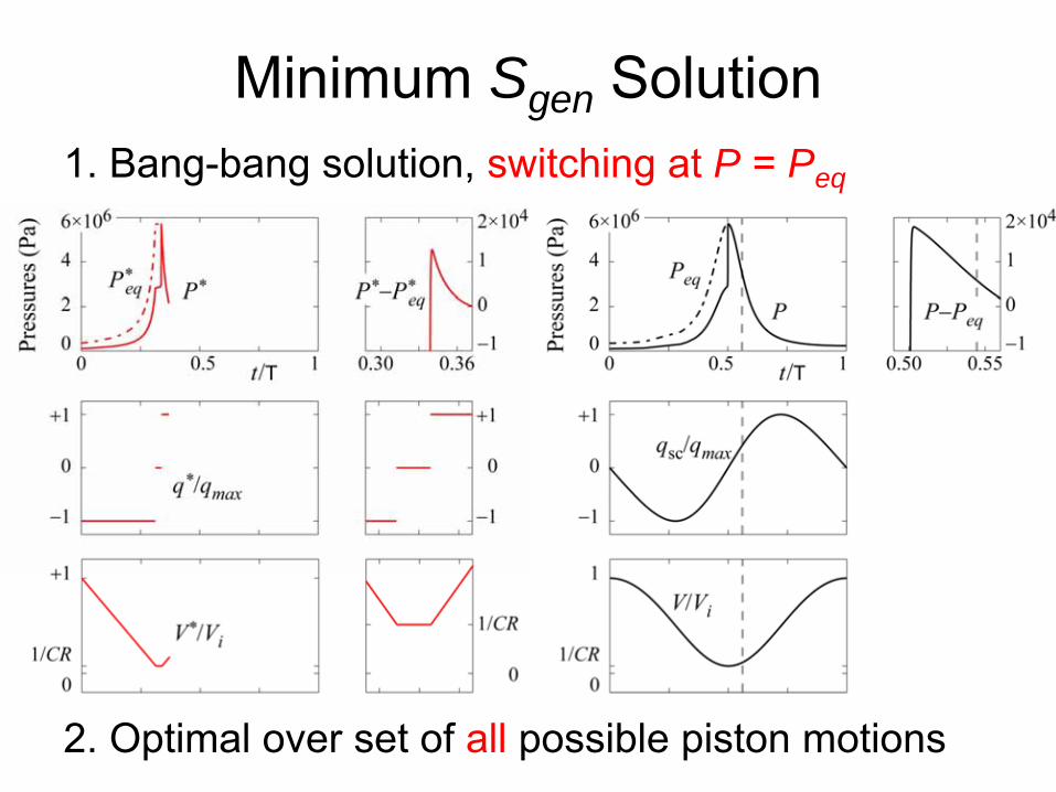
Minimum Sgen Solution1. Bang-bang solution, switching at P = Peq
2. Optimal over set of all
possible piston motions
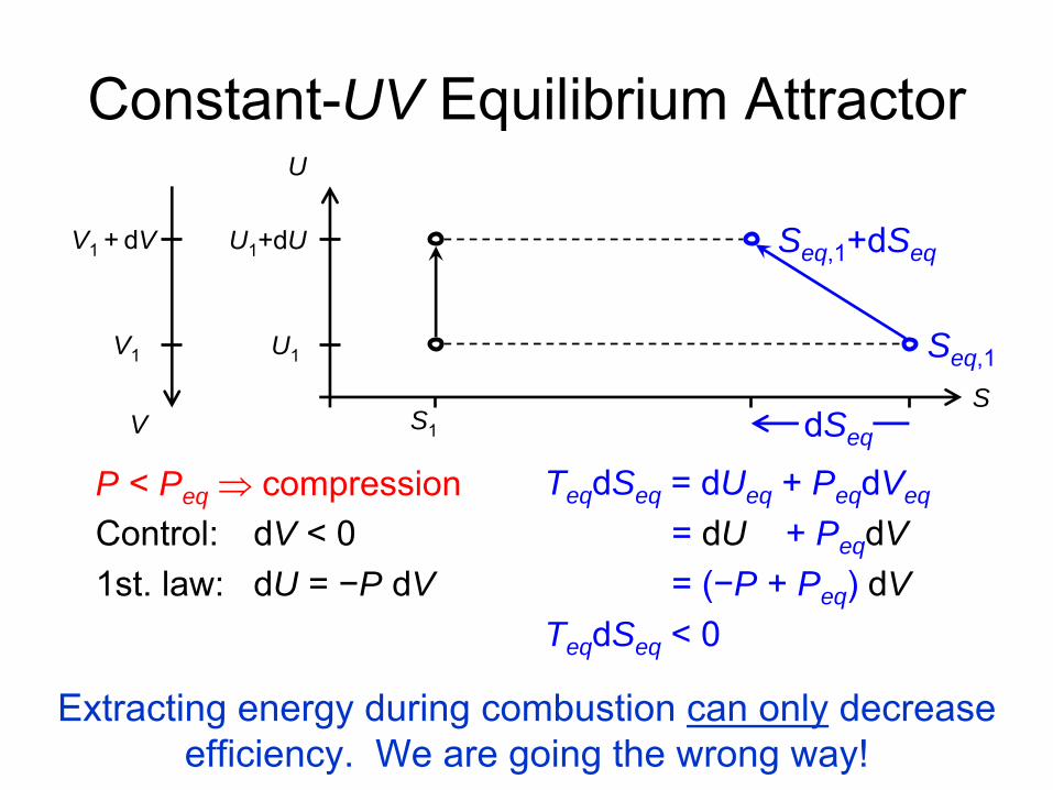
P < Peq ⇒ compressionControl: dV < 01st. law: dU = −P dV
Constant-UV Equilibrium Attractor
Teq dSeq = dUeq + Peq dVeq
= dU + Peq dV= (−P + Peq ) dV
Teq dSeq < 0
V1 + dV
V1
U1
+dU
V
U1
U
S
Seq,1
S1
Seq,1
+dSeq
dSeq
Extracting energy during combustion can only
decrease efficiency. We are going the wrong way!

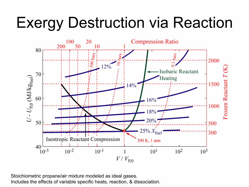
Exergy Destruction via Reaction
Stoichiometric propane/air mixture modeled as ideal gases. Includes the effects of variable specific heats, reaction, & dissociation.
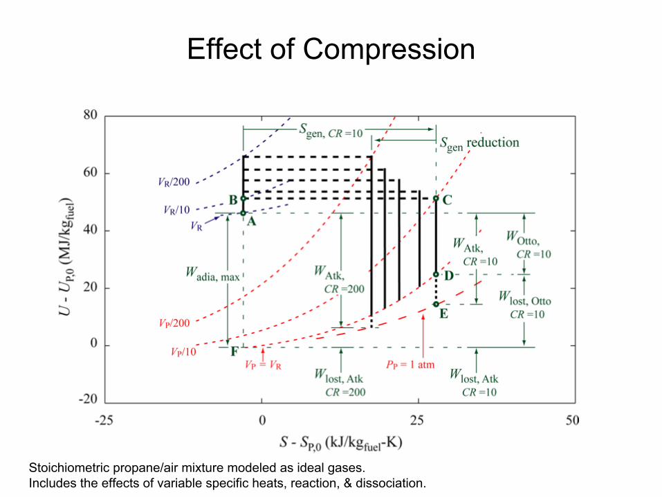
Effect of Compression
Stoichiometric propane/air mixture modeled as ideal gases. Includes the effects of variable specific heats, reaction, & dissociation.
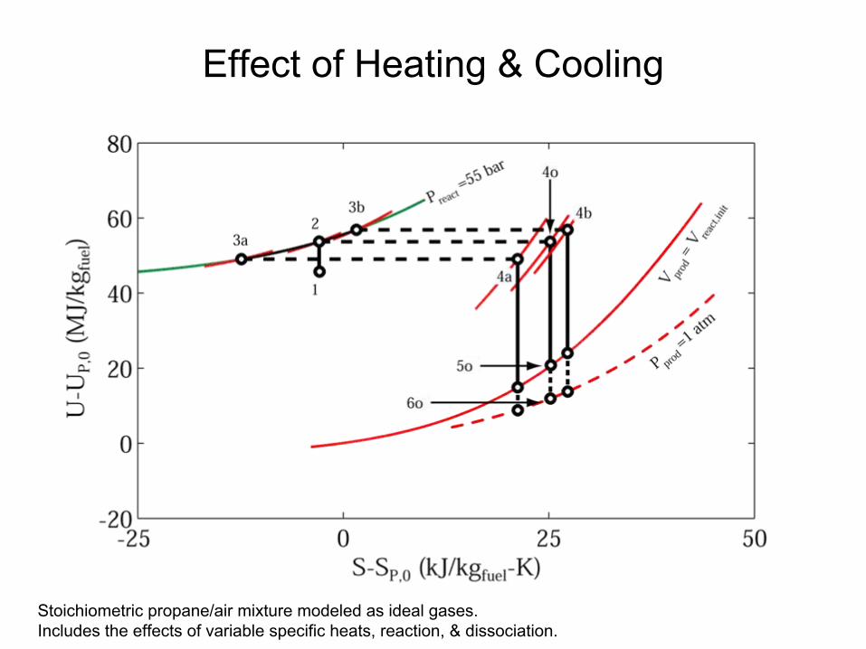
Effect of Heating & Cooling
Stoichiometric propane/air mixture modeled as ideal gases. Includes the effects of variable specific heats, reaction, & dissociation.

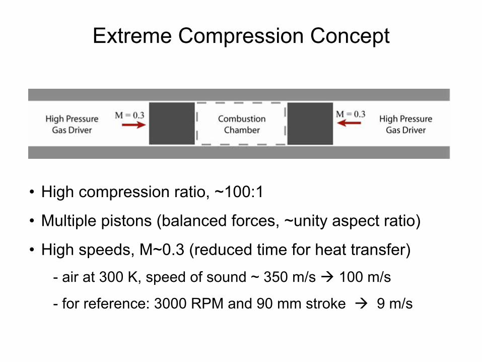
Extreme Compression Concept
•
High compression ratio, ~100:1
•
Multiple pistons (balanced forces, ~unity aspect ratio)
•
High speeds, M~0.3 (reduced time for heat transfer)
-
air at 300 K, speed of sound ~ 350 m/s 100 m/s
-
for reference: 3000 RPM and 90 mm stroke 9 m/s
55
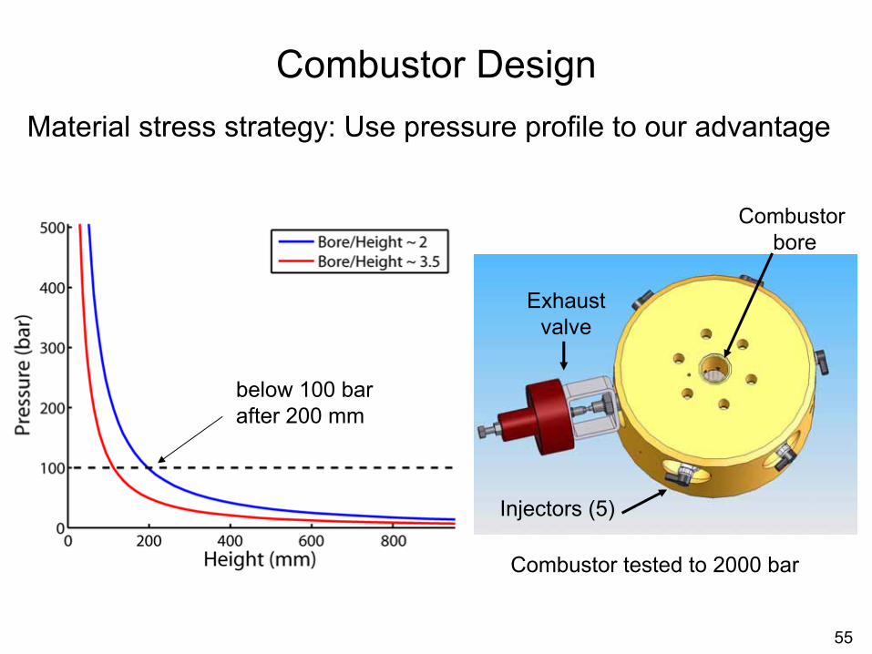
Combustor Design
Combustor tested to 2000 bar
Material stress strategy: Use pressure profile to our advantage
Combustor bore
below 100 bar after 200 mm
Injectors (5)
Exhaust valve
56
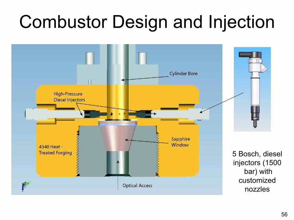
Combustor Design and Injection
5 Bosch, diesel injectors (1500
bar) withcustomized
nozzles
57
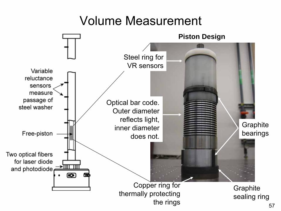
Volume Measurement
Optical bar code. Outer diameter
reflects light, inner diameter
does not.Graphite bearings
Copper ring for thermally protecting
the rings
Graphitesealing ring
Piston Design
Steel ring for VR sensors
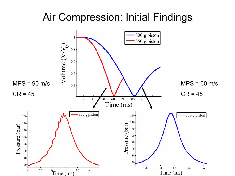
5878 80 82 84 86
20
40
60
80
100
120
140
160
Time (ms)
Pres
sure
(bar
)
800 g piston
58 59 60 61 62 63
20
40
60
80
100
120
140
160
Time (ms)
Pres
sure
(bar
)
350 g piston
30 40 50 60 70 80 90 100
0.2
0.4
0.6
0.8
1
Time (ms)
Vol
ume
(V/V
0)
800 g piston350 g piston
Air Compression: Initial Findings
MPS = 90 m/s
CR = 45
MPS = 60 m/s
CR = 45
59
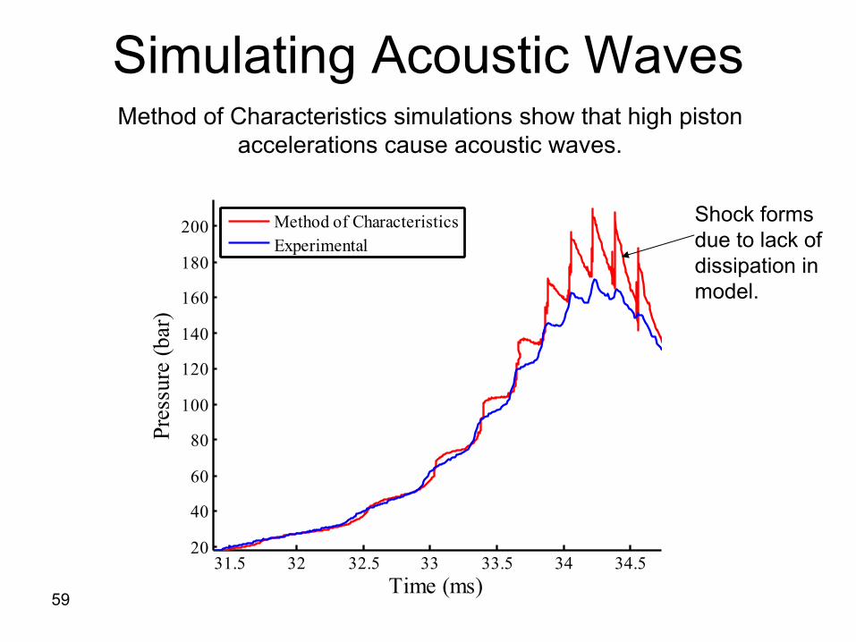
31.5 32 32.5 33 33.5 34 34.520
40
60
80
100
120
140
160
180
200
Time (ms)
Pres
sure
(bar
)
Method of CharacteristicsExperimental
Simulating Acoustic WavesMethod of Characteristics simulations show that high piston
accelerations cause acoustic waves.
Shock forms due to lack of dissipation in model.
60
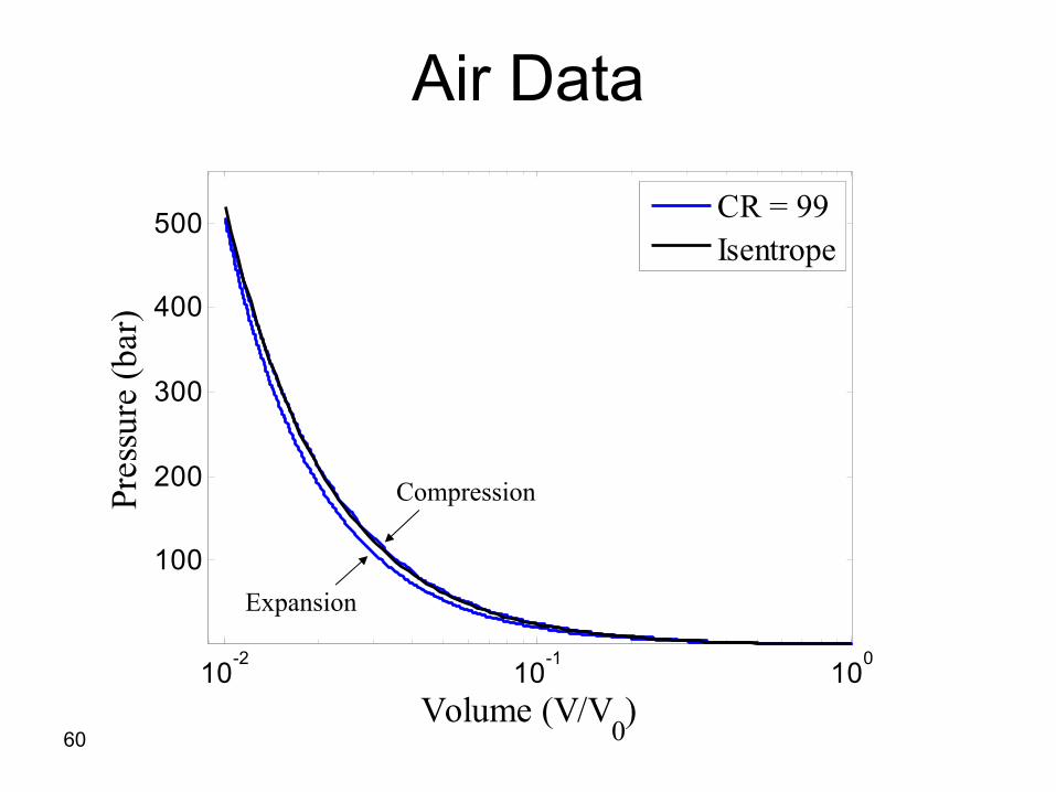
Air Data
10-2 10-1 100
100
200
300
400
500
Volume (V/V0)
Pres
sure
(bar
)
CR = 99Isentrope
Compression
Expansion
61
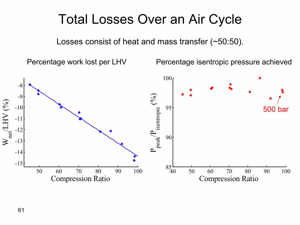
50 60 70 80 90 100-15
-14
-13
-12
-11
-10
-9
-8
Compression Ratio
Wne
t/LH
V (%
)
40 50 60 70 80 90 10085
90
95
100
Compression Ratio
P peak
/Pis
entro
pic (%
)
Total Losses Over an Air CycleLosses consist of heat and mass transfer (~50:50).
Percentage work lost per LHV Percentage isentropic pressure achieved
500 bar
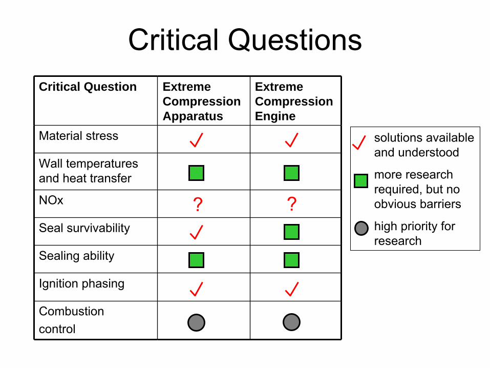
Critical QuestionsCritical Question Extreme
Compression Apparatus
Extreme Compression Engine
Material stress
Wall temperatures and heat transfer
NOx
Seal survivability
Sealing ability
Ignition phasing
Combustioncontrol
solutions available and understood
more research required, but no obvious barriers
high priority for research
? ?

64
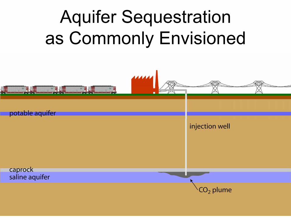
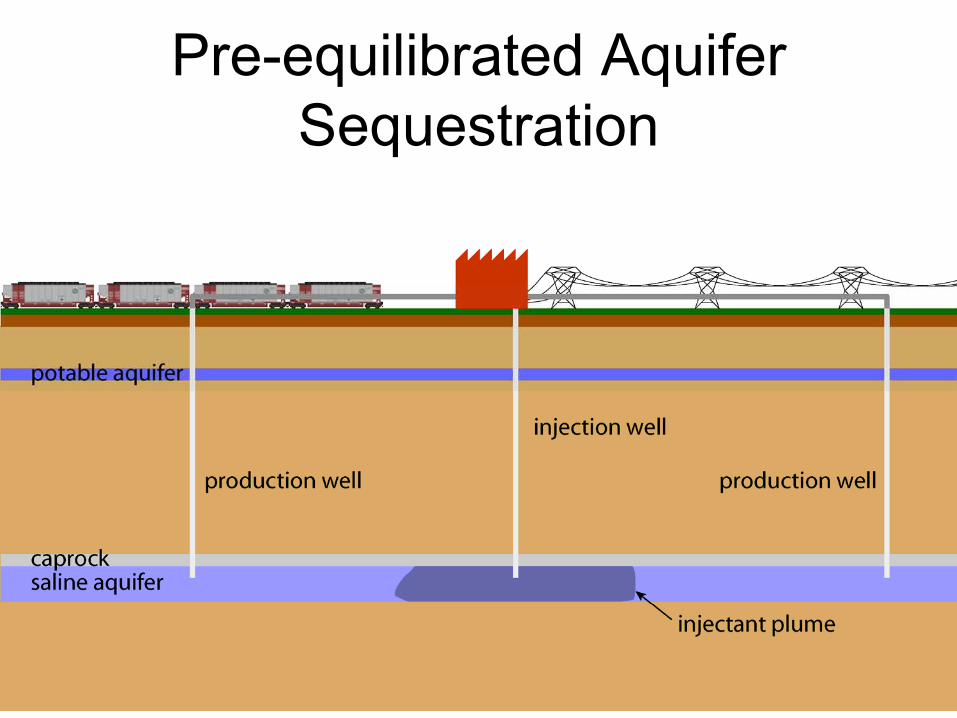
Aquifer Sequestration as Commonly Envisioned
65
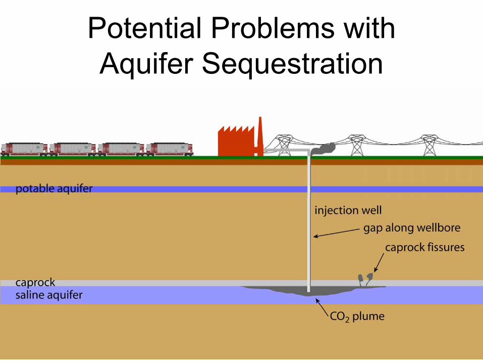
Potential Problems with Aquifer Sequestration
66
Pre-equilibrated Aquifer Sequestration
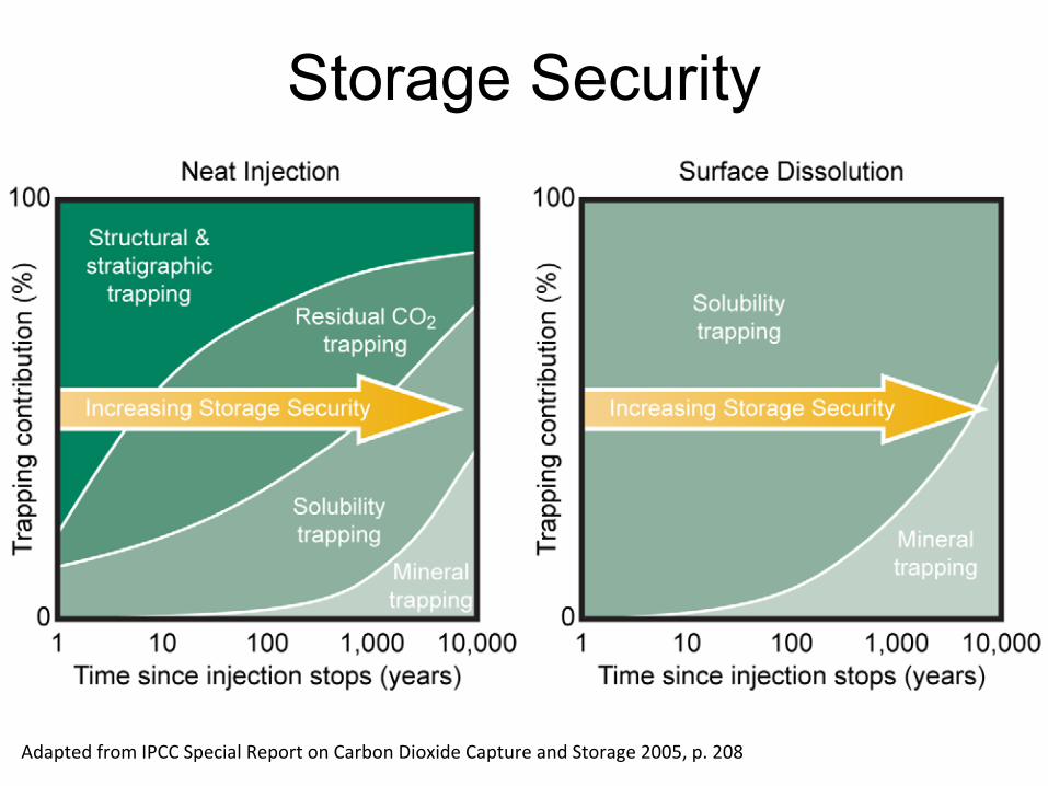
Storage Security
Adapted from IPCC Special Report on Carbon Dioxide Capture and Storage 2005, p. 208
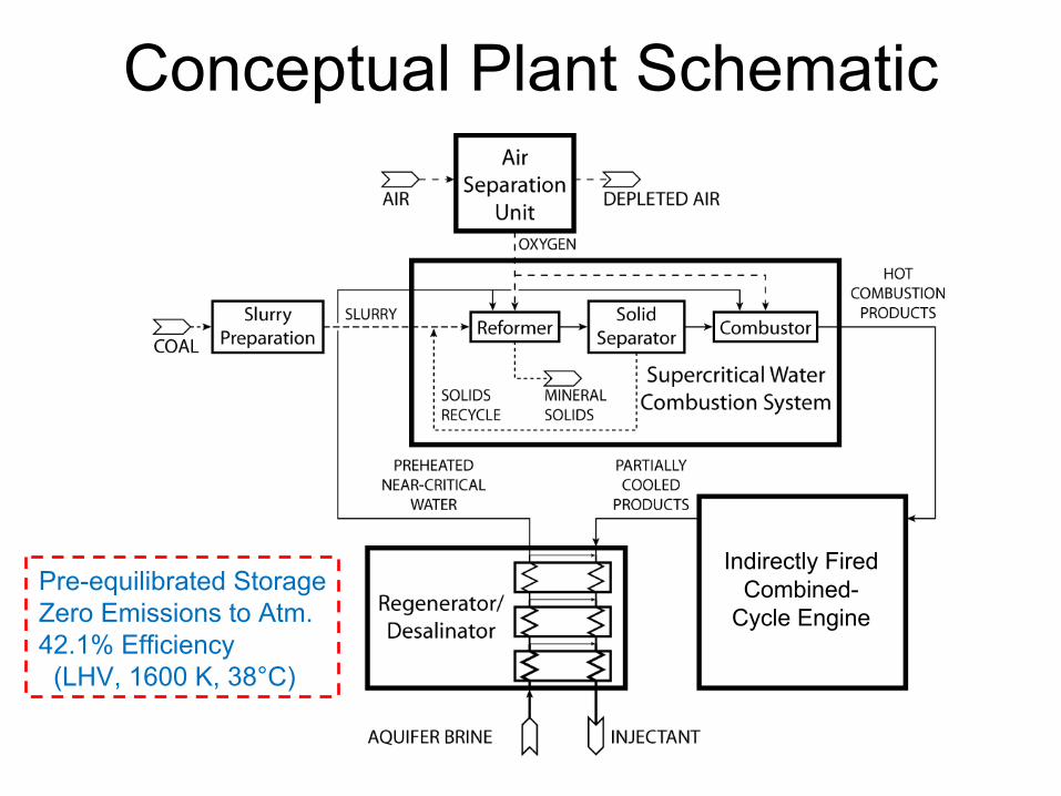
Conceptual Plant Schematic
Indirectly FiredCombined-
Cycle Engine
Pre-equilibrated StorageZero Emissions to Atm.42.1% Efficiency(LHV, 1600 K, 38°C)
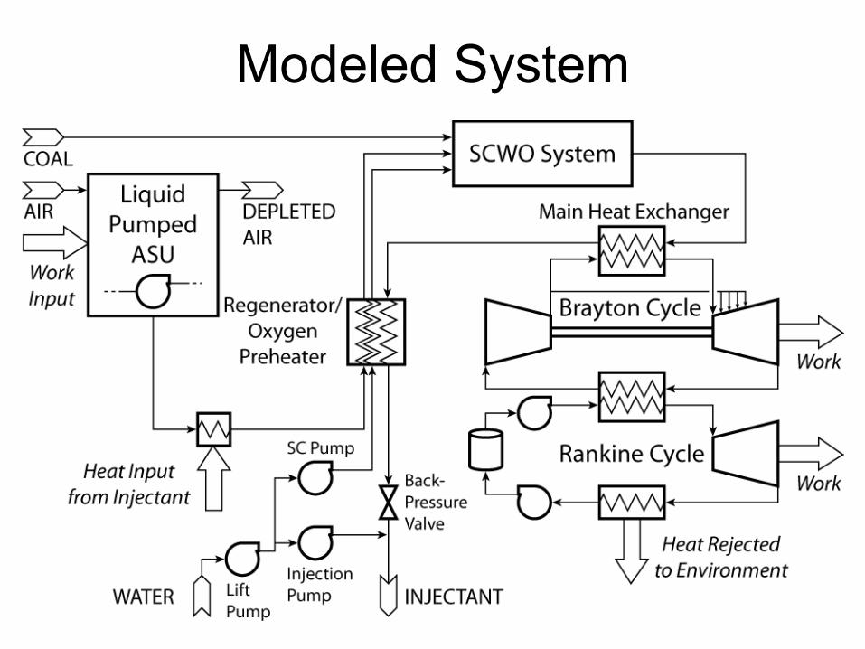
Modeled System
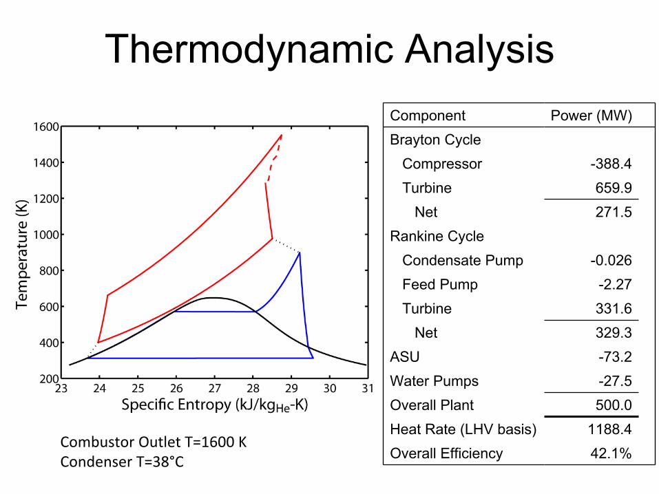
Thermodynamic AnalysisComponent Power (MW)Brayton Cycle
Compressor -388.4Turbine 659.9
Net 271.5Rankine Cycle
Condensate Pump -0.026Feed Pump -2.27Turbine 331.6
Net 329.3ASU -73.2Water Pumps -27.5Overall Plant 500.0Heat Rate (LHV basis) 1188.4Overall Efficiency 42.1%
Combustor Outlet T=1600 KCondenser T=38°C
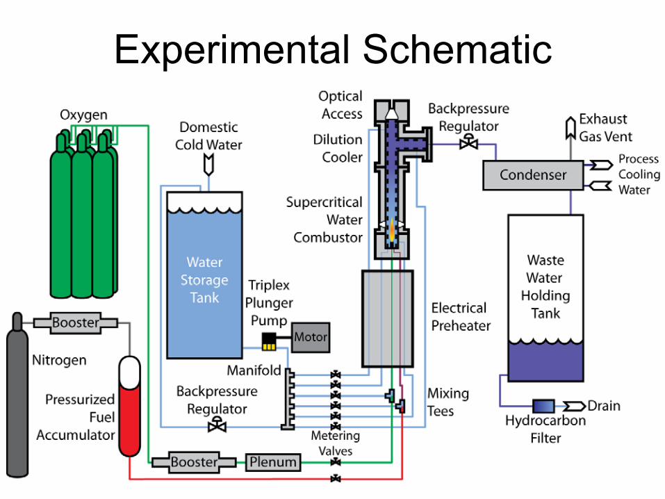
Experimental Schematic
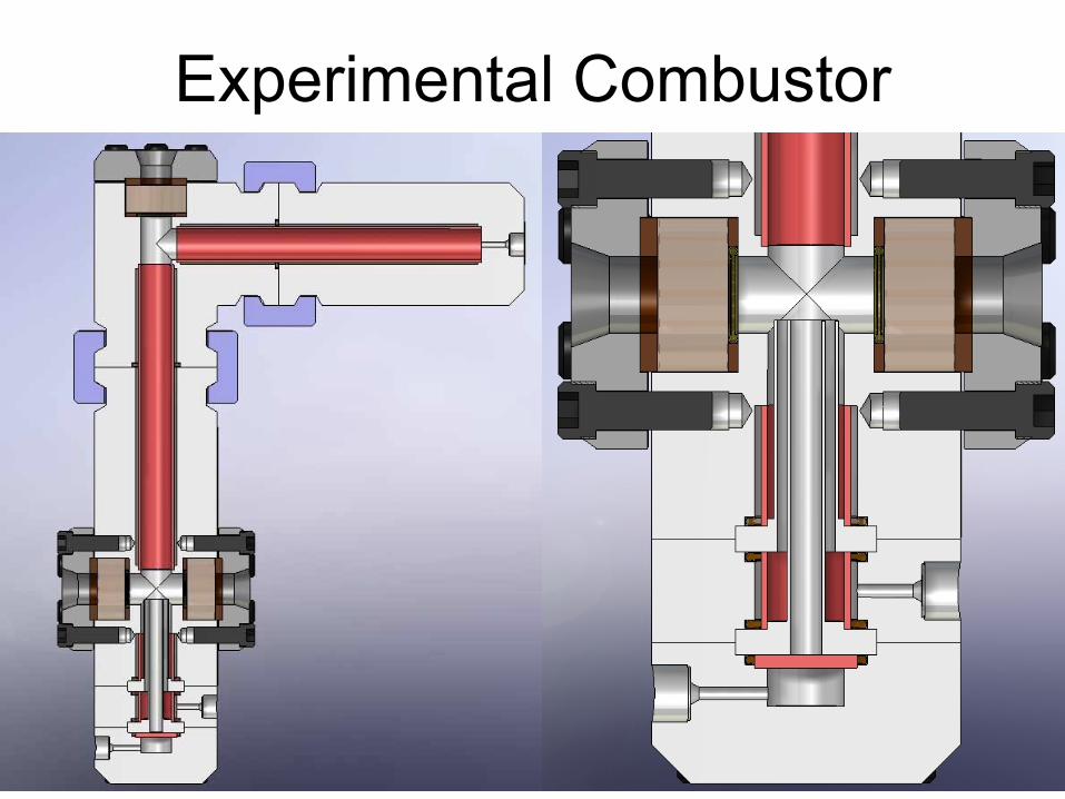
Experimental Combustor

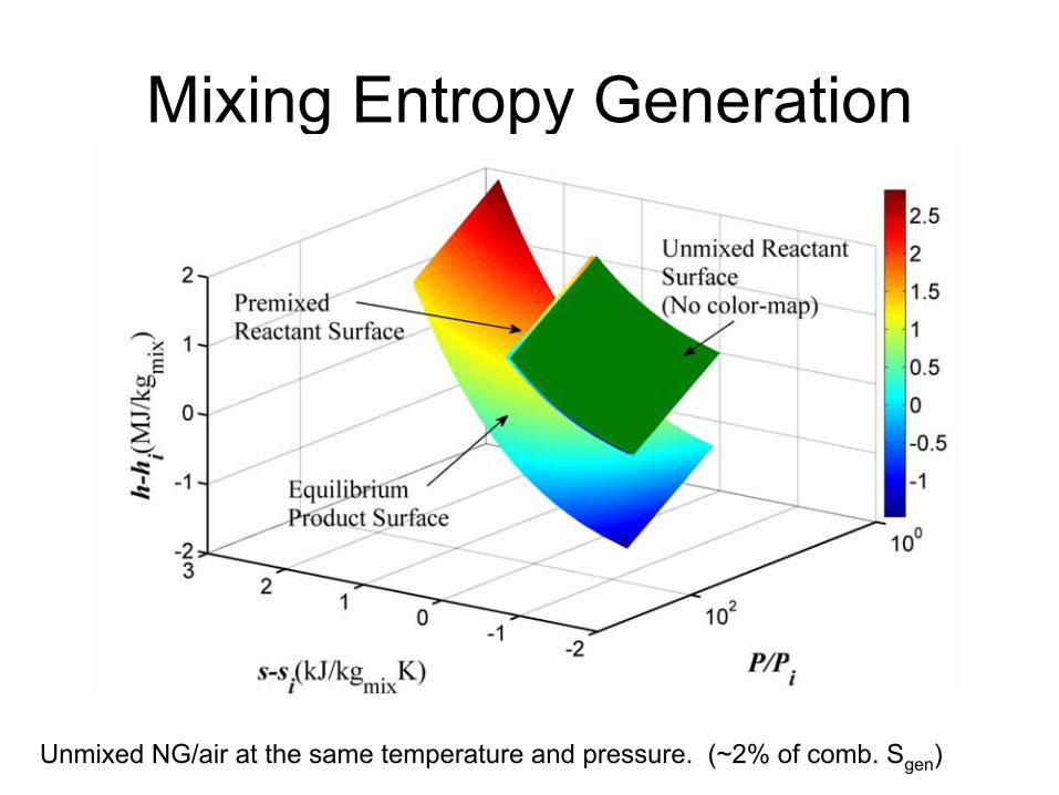
Mixing Entropy Generation
Unmixed NG/air at the same temperature and pressure. (~2% of comb. Sgen
)
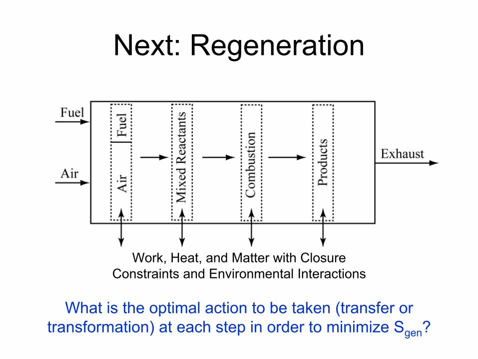
Next: Regeneration
What is the optimal action to be taken (transfer or transformation) at each step in order to minimize Sgen
?
Work, Heat, and Matter with Closure Constraints and Environmental Interactions
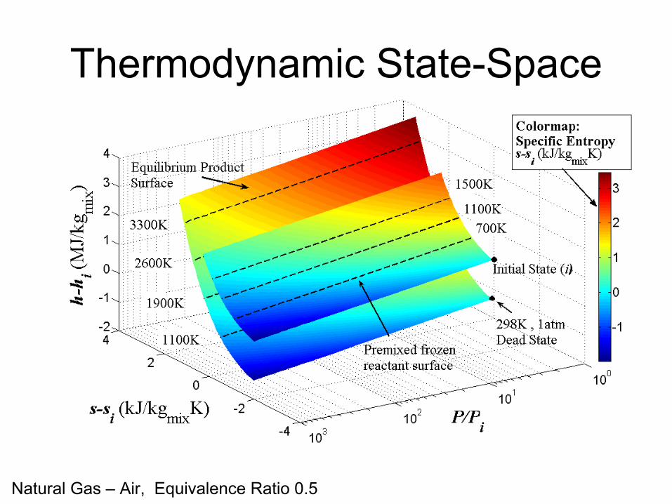
Thermodynamic State-Space
Natural Gas –
Air, Equivalence Ratio 0.5

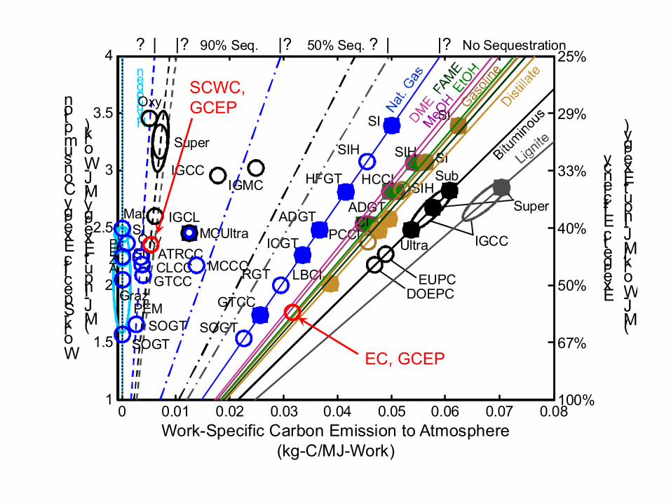
0 0.01 0.02 0.03 0.04 0.05 0.06 0.07 0.081
1.5
2
2.5
3
3.5
4
Work-Specific Carbon Emission to Atmosphere (kg-C/MJ-Work)
Wor
k-S
peci
fic E
xerg
y C
onsu
mpt
ion
(MJ-
Exe
rgy/
MJ-
Wor
k)
6FB
LM6000
LMS100
STIG
GTCC-H
Sub.Super
Elsam
EUDOE
Super-SFAGE1GE2
GE3Shell-SFAEgas
GTCC-SFA
GTCC-SFA
Super-SFAOxyPC-SFA
GE3Shell-SFA Sub.
Super
EUDOE
Super
ShellUltra
GE
Shell
Super
GE
ShellOxyPC
FGC1FGC2ATR
OxyNG
SI
SI-H
DICI
LBCI
LM6000DSIH2
PEM
PEM
PEM
SIMeOH
SIMeOH
CLSC
CLCC
SOGT-MSOGT-CASOGT-CBSOGT-CB
MC-Ultra-Coal-NG
SOGT-RASOGT-RBSOGT-RC
SOGT-ZSOGT-BA
SOGT-BB
SOGT-BCSOGT-C
MCGC-RAMCGC-RB
MCNG-RA
MCNG-RB
AZEPAZEPGraz
ATR-GTCCWC-K
SOGT-K
WC-GWC-G
CESMAT
100%
67%
50%
40%
33%
29%
25%
0 0.01 0.02 0.03 0.04 0.05 0.06 0.07 0.081
1.5
2
2.5
3
3.5
4
100%
67%
50%
40%
33%
29%
25%
Sub
Super
DOEPCEUPC
Ultra IGCC
SI
SIH
CI
Work-Specific Carbon Emission to Atmosphere(kg-C/MJ-Work)
Work-Specific Exergy Consumption
(MJ-Input-Exergy/MJ-Work)
Exergetic Efficiency
(MJ-Work/MJ-Input-Exergy)
ADGT
ICGT
GTCC
SOGT
RGT
HFGT
SI
SIH
CI
LBCI
ADGT
HCCI
PCCI
Hydrogen
SI
PEM
SIH
|? No Sequestration|? 50% Seq. ? |? | |? 90% Seq.
SI
SIHIGCC
Super
Oxy
GTCC
SOGT
OxyATRCCCLCC
IGCLMat
Graz
SOGT
AZEP
MCUltra
MCCC
IGMC
EC, GCEP
SCWC,
GCEP