Embed Size (px)
Citation preview
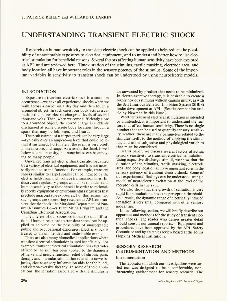
1. PATRICK REILLY and WILLARD D. LARKIN
UNDERSTANDING TRANSIENT ELECTRIC SHOCK
. ~esearch on human sensitivity to transient electric shock can be applied to help reduce the possibIlIty of unacceptable exposures to electrical equipment, and to understand better how to use electrical stimulation for beneficial reasons. Several factors affecting human sensitivity have been explored at APL and are reviewed here. Time duration of the stimulus, tactile masking, electrode area, and body location all have important roles in the sensory potency of the stimulus. Some of the important variables in sensitivity to transient shock can be understood by using neuroelectric models.
INTRODUCTION Exposure to transient electric shock is a common
occurrence-we have all experienced shocks when we walk across a carpet on a dry day and then touch a grounded object. In such cases, our body acts as a capacitor that stores electric charges at levels of several thousand volts. Then, when we come sufficiently close to a grounded object, the stored charge is suddenly discharged at some discrete body location through a spark that may be felt, seen, and heard.
The peak current of a carpet spark can be very large -typically over an ampere-a level that could be lethal if sustained. Fortunately, the event is very brief, in the microsecond range. As a result, the shock is well below a lethal intensity, but nonetheless can be annoying to many people.
Unwanted transient electric shock can also be caused by a variety of electrical equipment, and it is not necessarily related to malfunction. For example, transient shocks similar to carpet sparks can be induced by the electric fields from high voltage transmission lines. Industry and regulatory groups would like to understand human sensitivity to these shocks in order to rationally specify equipment or environmental safeguards that preclude unacceptable exposures. For this reason, two such groups are sponsoring research at APL on transient electric shock: the Maryland Department of Natural Resources Power Plant Siting Program and the Canadian Electrical Association.
The interest of our sponsors is that the quantification of human reactions to transient shock can be applied to help reduce the possibility of unacceptable public and occupational exposures. Electric shock is treated as an unintended and undesirable event.
There are also many biomedical applications where transient electrical stimulation is used beneficially. For example, transient electrical stimulation via electrodes affixed to the skin has been applied to the diagnosis of nerve and muscle function, relief of chronic pain, therapy and muscular stimulation related to nerve injuries, electrosensory information aids for the blind and electro-aversive therapy. In some of these appli: cations, the sensation associated with the stimulus is
296
an unwanted by-product that needs to be minimized. In electro-aversive therapy, it is desirable to create a highly noxious stimulus without causing injury, as with the Self Injurious Behavior Inhibition System (SIBIS) under development at APL. (See the companion article by Newman in this issue.)
Whether transient electrical stimulation is intended or unintended, it is important to understand the factors that affect human sensitivity. There is no single number that can be used to quantify sensory sensitivity. Rather, there are many parameters related to the stimulus itself, to the method of applying the stimulus, and to the subjective and physiological variables that must be considered. .
In this paper, we discuss several factors affecting sensory sensitivity to transient electrical stimulation. Using capacitive discharge stimuli, we show that the duration of the stimulus, tactile masking, electrode area, and body location all have important roles in the sensory potency of transient electric shock. Some of our experimental findings can be understood using a model of neuroelectric excitation at the level of the receptor cells in the skin.
We also show that the growth of sensation is very rapid for stimulation above the perception threshold. As a result, the dynamic range of electrically induced sensation is very small compared with other sensory modalities.
In the following section, we will briefly describe our apparatus and methods for the study of transient electrical shocks. The reader who desires greater detail should consult our annual reports. 1-3 Equipment and procedures have been approved by the APL Safety Committee and by an ethics review board at the 10hns Hopkins Medical Institutions.
SENSORY RESEARCH: INSTRUMENTATION AND METHODS
Instrumentation The laboratory in which our investigations were car
ried out was designed to be a comfortable, nonthreatening environment for sensory research. The
Johns Hopkins A PL Technical Digest
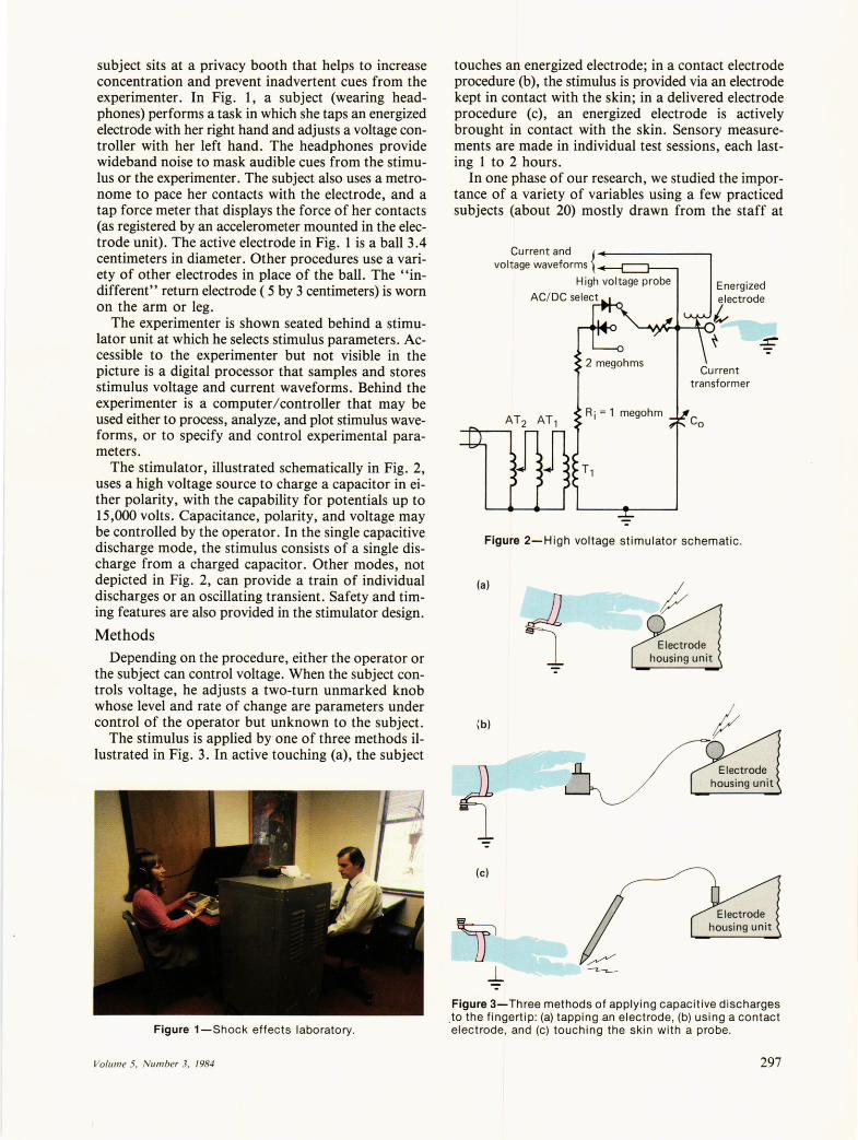
subject sits at a privacy booth that helps to increase concentration and prevent inadvertent cues from the experimenter. In Fig. 1, a subject (wearing headphones) performs a task in which she taps an energized electrode with her right hand and adjusts a voltage controller with her left hand. The headphones provide wideband noise to mask audible cues from the stimulus or the experimenter. The subject also uses a metronome to pace her contacts with the electrode, and a tap force meter that displays the force of her contacts (as registered by an accelerometer mounted in the electrode unit). The active electrode in Fig. 1 is a ball 3.4 centimeters in diameter. Other procedures use a variety of other electrodes in place of the ball. The "indifferent" return electrode ( 5 by 3 centimeters) is worn on the arm or leg.
The experimenter is shown seated behind a stimulator unit at which he selects stimulus parameters. Accessible to the experimenter but not visible in the picture is a digital processor that samples and stores stimulus voltage and current waveforms. Behind the experimenter is a computer/controller that may be used either to process, analyze, and plot stimulus waveforms, or to specify and control experimental parameters.
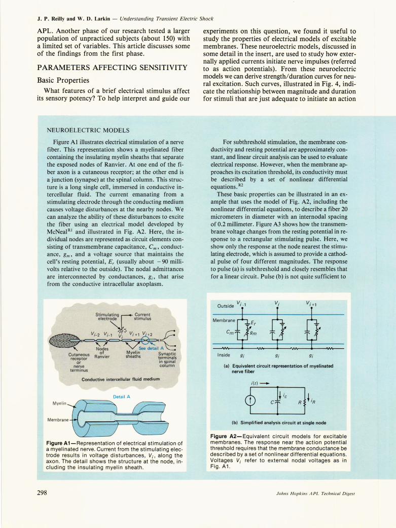
The stimulator, illustrated schematically in Fig. 2, uses a high voltage source to charge a capacitor in either polarity, with the capability for potentials up to 15,000 volts. Capacitance, polarity, and voltage may be controlled by the operator. In the single capacitive discharge mode, the stimulus consists of a single discharge from a charged capacitor. Other modes, not depicted in Fig. 2, can provide a train of individual discharges or an oscillating transient. Safety and timing features are also provided in the stimulator design.
Methods Depending on the procedure, either the operator or
the subject can control voltage. When the subject controls voltage, he adjusts a two-turn unmarked knob whose level and rate of change are parameters under control of the operator but unknown to the subject.
The stimulus is applied by one of three methods illustrated in Fig. 3. In active touching (a), the subject
Figure 1-Shock effects laboratory.
Volum e 5, Number 3, 1984
touches an energized electrode; in a contact electrode procedure (b), the stimulus is provided via an electrode kept in contact with the skin; in a delivered electrode procedure (c), an energized electrode is actively brought in contact with the skin. Sensory measurements are made in individual test sessions, each lasting 1 to 2 hours.
In one phase of our research, we studied the importance of a variety of variables using a few practiced subjects (about 20) mostly drawn from the staff at
Current and { voltage waveforms
High voltage probe
AC/ DC select
Current transformer
Figure 2-High voltage stimulator schematic .
(a)
housing unit
(b)
housing unit
(c)
Figure 3-Three methods of applying capacitive discharges .to the fingertip: (a) tapping an electrode , (b) using a contact electrode, and (c) touching the skin with a probe.
297
J. P. Reilly and W. D. Larkin - Understanding Transient Electric Shock
APL. Another phase of our research tested a larger population of unpracticed subjects (about 150) with a limited set of variables. This article discusses some of the findings from the first phase.
PARAMETERS AFFECTING SENSITIVITY
Basic Properties What features of a brief electrical stimulus affect
its sensory potency? To help interpret and guide our
NEUROELECTRIC MODELS
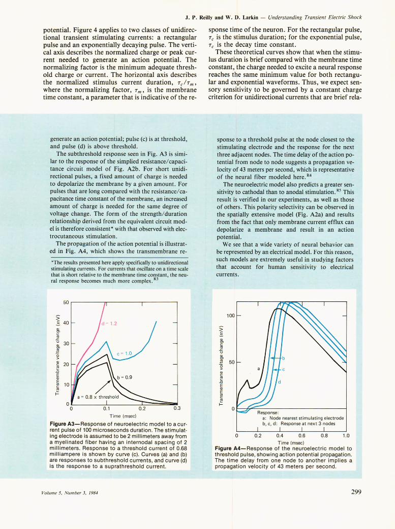
Figure A 1 illustrates electrical stimulation of a nerve fiber. This representation shows a myelinated fiber containing the insulating myelin sheaths that separate the exposed nodes of Ranvier. At one end of the fiber axon is a cutaneous receptor; at the other end is a junction (synapse) at the spinal column. This structure is a long single cell, immersed in conductive intercellular fluid. The current emanating from a stimulating electrode through the conducting medium causes voltage disturbances at the nearby nodes. We can analyze the ability of these disturbances to excite the fiber using an electrical model developed by McNeal R I and illustrated in Fig. A2 . Here, the individual nodes are represented as circuit elements consisting of transmembrane capacitance, em, conductance, gm' and a voltage source that maintains the cell's resting potential, Er (usually about - 90 millivolts relative to the outside). The nodal admittances are interconnected by conductances, gi , that arise from the conductive intracellular axoplasm.
Stimula~ing Current electrode stimulus
I~
V' V -:.. ,- V' V ' { •,.,,:. ~ ,,,-.; _- .. -_....... I
'::':.-:':-;~~;. '" Nodes See detai l A
Cutaneous of . Myelin Synaptic receptor Ranvler sheaths terminals
or in spinal nerve column
terminus
Conductive intercellular fluid medium
Detail A
M':::::'~ ~ 6 Figure A1-Representation of electrical stimulation of a myelinated nerve. Current from the stimulating elec· trode results in voltage disturbances, Vi, along the axon. The detail shows the structure at the node, in· cluding the insulating myelin sheath.
298
experiments on this question, we found it useful to study the properties of electrical models of excitable membranes. These neuroelectric models, discussed in some detail in the insert, are used to study how externally applied currents initiate nerve impulses (referred to as action potentials). From these neuroelectric models we can derive strength/duration curves for neural excitation. Such curves, illustrated in Fig. 4, indicate the relationship between magnitude and duration for stimuli that are just adequate to initiate an action
For subthreshold stimulation, the membrane conductivity and resting potential are approximately constant, and linear circuit analysis can be used to evaluate electrical response. However, when the membrane approaches its excitation threshold, its conductivity must be described by a set of nonlinear differential equations. R2
These basic properties can be illustrated in an example that uses the model of Fig. A2, including the nonlinear differential equations, to describe a fiber 20 micrometers in diameter with an internodal spacing of 0.2 millimeter. Figure A3 shows how the transmembrane voltage changes from the resting potential in response to a rectangular stimulating pulse. Here, we show only the response at the node nearest the stimulating electrode, which is assumed to provide a cathodal pulse of four different magnitudes. The response to pulse (a) is subthreshold and closely resembles that for a linear circuit. Pulse (b) is not quite sufficient to
Outside Vi.,
Inside gi 9i 9i
(a) Equivalent circuit representation of myelinated nerve fiber
(b) Simplified analysis circuit at single node
Figure A2-Equivalent circuit models for excitable membranes. The response near the action potential threshold requires that the membrane conductance be described by a set of nonlinear differential equations . Voltages Vi refer to external nodal voltages as in Fig. A1.
Johns Hopkins A PL Technical Digest
J. P. Reilly and W. D. Larkin - Understanding Transient Electric Shock
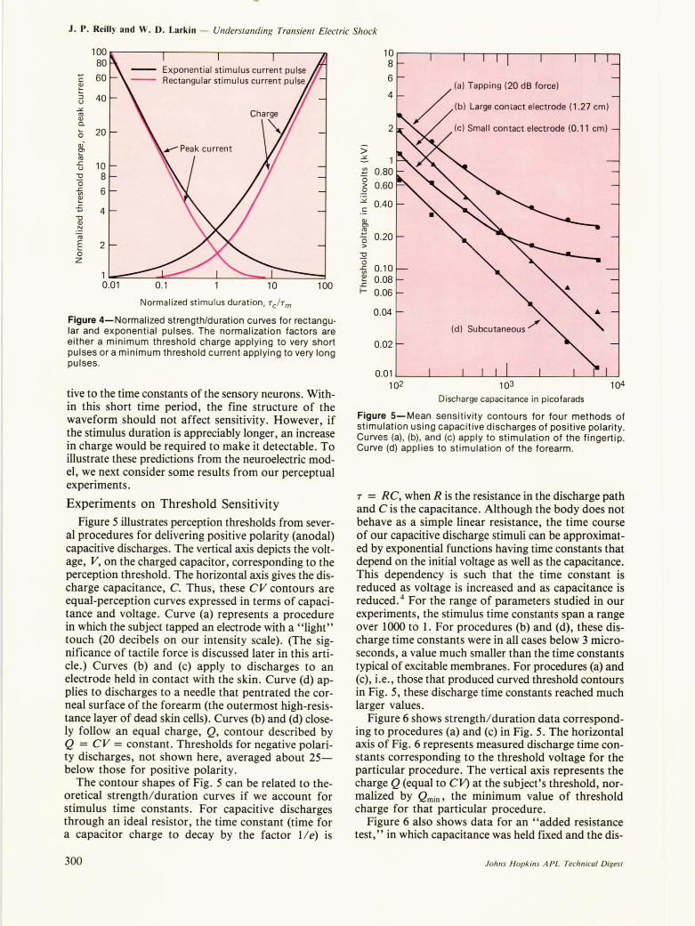
potential. Figure 4 applies to two classes of unidirectional transient stimulating currents: a rectangular pulse and an exponentially decaying pulse. The vertical axis describes the normalized charge or peak current needed to generate an action potential. The normalizing factor is the minimum adequate threshold charge or current. The horizontal axis describes the normalized stimulus current duration, Tc lT m'
where the normalizing factor, T m' is the membrane time constant, a parameter that is indicative of the re-
generate an action potential; pulse (c) is at threshold, and pulse (d) is above threshold.
The subthreshold response seen in Fig. A3 is similar to the response of the simplied resistance/capacitance circuit model of Fig. A2b. For short unidirectional pulses, a fixed amount of charge is needed to depolarize the membrane by a given amount. For pulses that are long compared with the resistance/capacitance time constant of the membrane, an increased amount of charge is needed for the same degree of voltage change. The form of the strength/duration relationship derived from the equivalent circuit model is therefore consistent* with that observed with electrocutaneous stimulation.
The propagation of the action potential is illustrated in Fig. A4, which shows the transmembrane re-
*The results presented here apply specifically to unidirectional stimulating currents. For currents that oscillate on a time scale that is short relative to the membrane time constant, the neural response becomes much more complex. R3
50~------~~--------~--------~
;; E 40 Q) en c co
.s:. u 30 Q) en ~ 0 > Q)
20 c co .0 E Q)
~ 10 c co ~
0 0 0.1 0.2 0.3
Time (msec)
Figure A3-Response of neuroelectric model to a current pulse of 100 microseconds duration. The stimulating electrode is assumed to be 2 millimeters away from a myelinated fiber having an internodal spacing of 2 millimeters. Response to a threshold current of 0.68 milliampere is shown by curve (c). Curves (a) and (b) are responses to subthreshold currents, and curve (d) is the response to a suprathreshold current.
Volume 5, Number 3, 1984
sponse time of the neuron. For the rectangular pulse, Tc is the stimulus duration; for the exponential pulse, Tc is the decay time constant.
These theoretical curves show that when the stimulus duration is brief compared with the membrane time constant, the charge needed to excite a neural response reaches the same minimum value for both rectangular and exponential waveforms. Thus, we expect sensory sensitivity to be governed by a constant charge criterion for unidirectional currents that are brief rela-
sponse to a threshold pulse at the node closest to the stimulating electrode and the response for the next three adjacent nodes. The time delay of the action potential from node to node suggests a propagation velocity of 43 meters per second, which is representative of the neural fiber modeled here. R4
The neuroelectric model also predicts a greater sensitivity to cathodal than to anodal stimulation. R5 This result is verified in our experiments, as well as those of others. This polarity selectivity can be observed in the spati~lly extensive model (Fig. A2a) and results from the fact that only membrane current efflux can depolarize a membrane and result in an action potential.
We see that a wide variety of neural behavior can be represented by an electrical model. For this reason, such models are extremely useful in studying factors that account for human sensitivity to electrical currents.
100
;; .s
Q) en c co
.s:. u Q) en .<g 50 a > Q) c co .0 E Q)
~ c co ~
0
o
Response:
0.2
a: Node nearest stimulating electrode b, c, d: Response at next 3 nodes
0.4 0 .6 0 .8 1.0
Time (msec) Figure A4-Response of the neuroelectric model to threshold pulse, showing action potential propagation. The time delay from one node to another implies a propagation velocity of 43 meters per second.
299
J. P. Reilly and W. D. Larkin - Understanding Transient Electric Shock
100 80
+-' 60 c ~ ::J 40 u
.:,L C\l OJ Q.
0 20 OJ-
~ C\l £. 10 u "0 8 "0 -ti 6 e £.
4 +-'
"0 OJ
. ~ C\l
E 2 0 z
0.1 10 100
Norma lized stimulus duration, Tch m
Figure 4-Normalized strengthlduration curves for rectangu· lar and exponential pulses. The normalization factors are either a minimum threshold charge applying to very short pulses or a minimum threshold current applying to very long pulses .
tive to the time constants of the sensory neurons. Within this short time period, the fine structure of the waveform should not affect sensitivity. However, if the stimulus duration is appreciably longer, an increase in charge would be required to make it detectable. To illustrate these predictions from the neuroelectric model, we next consider some results from our perceptual experiments.
Experiments on Threshold Sensitivity Figure 5 illustrates perception thresholds from sever
al procedures for delivering positive polarity (anodal) capacitive discharges. The vertical axis depicts the voltage, V, on the charged capacitor, corresponding to the perception threshold. The horizontal axis gives the discharge capacitance, C. Thus, these CV contours are equal-perception curves expressed in terms of capacitance and voltage. Curve (a) represents a procedure in which the subject tapped an electrode with a "light" touch (20 decibels on our intensity scale). (The significance of tactile force is discussed later in this article.) Curves (b) and (c) apply to discharges to an electrode held in contact with the skin. Curve (d) applies to discharges to a needle that pentrated the corneal surface of the forearm (the outermost high-resistance layer of dead skin cells). Curves (b) and (d) closely follow an equal charge, Q, contour described by Q = CV = constant. Thresholds for negative polarity discharges, not shown here, averaged about 25-below those for positive polarity.
The contour shapes of Fig. 5 can be related to theoretical strength/ duration curves if we account for stimulus time constants. For capacitive discharges through an ideal resistor, the time constant (time for a capacitor charge to decay by the factor 1/ e) is
300
10 8
6
4
2
(a) Tapping (20 dB force)
~ (b) Large con' act electrode (1.27 em)
(c) Small contact electrode (0.11 cm)
> ~ 1 V) 0.80 +-'
0 0.60 >
.2
.:,L 0.40
. ~ OJ Cl
~ 0.20 "0 >
:Q 0
-ti 0.10 e 0.08 £. I- 0.06
0.04
0.02
0.01 102 103 104
Discharge capacitance in picofarads
Figure 5-Mean sensitivity contours for four methods of stimulation using capacitive discharges of positive polarity. Curves (a) , (b), and (c) apply to stimulation of the fingertip. Curve (d) applies to stimulation of the forearm.
r = RC, when R is the resistance in the discharge path and C is the capacitance. Although the body does not behave as a simple linear resistance, the time course of our capacitive discharge stimuli can be approximated by exponential functions having time constants that depend on the initial voltage as well as the capacitance. This dependency is such that the time constant is reduced as voltage is increased and as capacitance is reduced. 4 For the range of parameters studied in our experiments, the stimulus time constants span a range over 1000 to 1. For procedures (b) and (d), these discharge time constants were in all cases below 3 microseconds, a value much smaller than the time constants typical of excitable membranes. For procedures (a) and (c), i.e., those that produced curved threshold contours in Fig. 5, these discharge time constants reached much larger values.
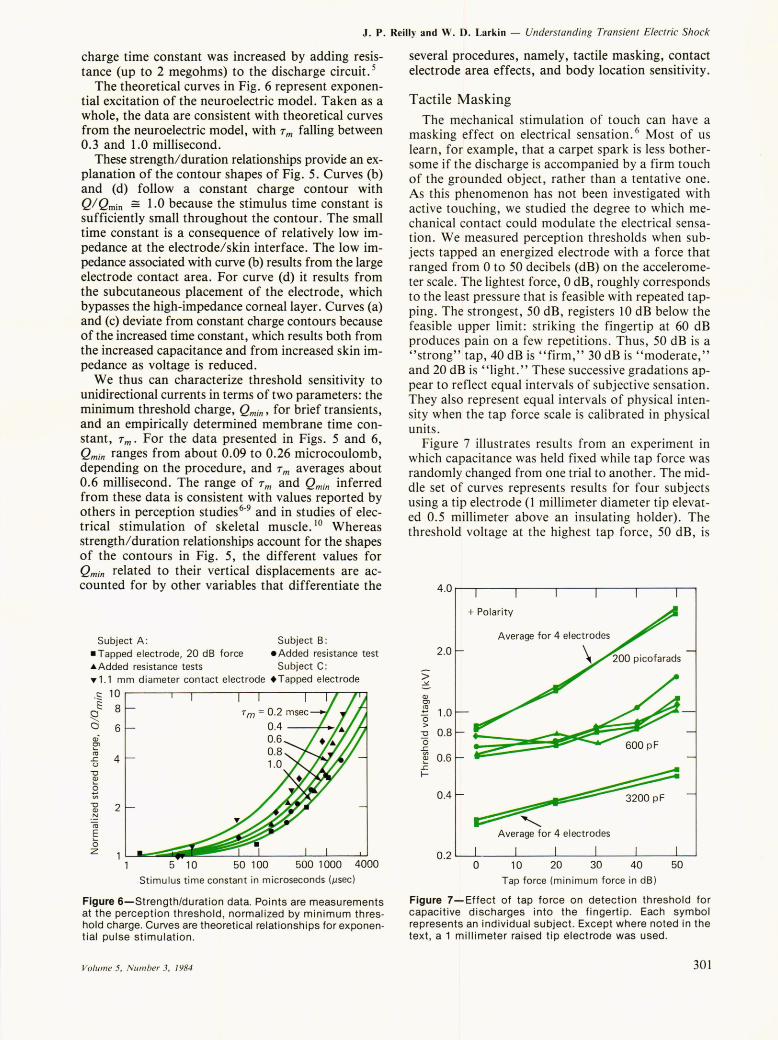
Figure 6 shows strength/duration data corresponding to procedures (a) and (c) in Fig. 5. The horizontal axis of Fig. 6 represents measured discharge time constants corresponding to the threshold voltage for the particular procedure. The vertical axis represents the charge Q (equal to CV) at the subject's threshold, normalized by Qrnin, the minimum value of threshold charge for that particular procedure.
Figure 6 also shows data for an "added resistance test, " in which capacitance was held fixed and the dis-
Johns Hopkins A PL Technical Digest
J. P. Reilly and W. D. Larkin - Understanding Transient Electric Shock
charge time constant was increased by adding resistance (up to 2 megohms) to the discharge circuit. 5
The theoretical curves in Fig. 6 represent exponential excitation of the neuroelectric model. Taken as a whole, the data are consistent with theoretical curves from the neuroelectric model, with 7 m falling between 0.3 and 1.0 millisecond.
These strength/duration relationships provide an explanation of the contour shapes of Fig. 5. Curves (b) and (d) follow a constant charge contour with Q/ Qrnin == 1.0 because the stimulus time constant is sufficiently small throughout the contour. The small time constant is a consequence of relatively low impedance at the electrode/skin interface. The low impedance associated with curve (b) results from the large electrode contact area. For curve (d) it results from the subcutaneous placement of the electrode, which bypasses the high-impedance corneal layer . Curves (a) and (c) deviate from constant charge contours because of the increased time constant, which results both from the increased capacitance and from increased skin impedance as voltage is reduced.
We thus can characterize threshold sensitivity to unidirectional currents in terms of two parameters: the minimum threshold charge, Qmin, for brief transients, and an empirically determined membrane time constant, 7 m. For the data presented in Figs. 5 and 6, Qmin ranges from about 0.09 to 0.26 microcoulomb, depending on the procedure, and 7 m averages about 0.6 millisecond. The range of 7 m and Qmin inferred from these data is consistent with values reported by others in perception studies 6-9 and in studies of electrical stimulation of skeletal muscle. 10 Whereas strength/ duration relationships account for the shapes of the contours in Fig. 5, the different values for Qmin related to their vertical displacements are accounted for by other variables that differentiate the
Subject A: Subject B: -Tapped electrode, 20 dB force eAdded resistance test .Added resistance tests Subject C: ..,1.1 mm diameter contact electrode. Tapped electrode
.S 10 t: 8
Q. a 6 Qi ~ ~ 4 u
"tJ Q)
g ] 2 .r:::! co E o z
1 L1 ....... ~::::::iii5 iiiii1 'Oii~~5~0~1 oLo----5o~0:-:-1 0~0:-::0:--~4000 Stimulus t ime constant in microseconds (,usec)
Figure 6-Strength/duration data. Points are measurements at the perception threshold , normalized by minimum threshold charge. Curves are theoretical relationships for exponential pulse stimulation .
Volume 5, Number 3, 1984
several procedures, namely, tactile masking, contact electrode area effects, and body location sensitivity.
Tactile Masking The mechanical stimulation of touch can have a
masking effect on electrical sensation. 6 Most of us learn, for example, that a carpet spark is less bothersome if the discharge is accompanied by a firm touch of the grounded object, rather than a tentative one. As this phenomenon has not been investigated with active touching, we studied the degree to which mechanical contact could modulate the electrical sensation. We measured perception thresholds when subjects tapped an energized electrode with a force that ranged from 0 to 50 decibels (dB) on the accelerometer scale. The lightest force, 0 dB, roughly corresponds to the least pressure that is feasible with repeated tapping. The strongest, 50 dB , registers 10 dB below the feasible upper limit: striking the fingertip at 60 dB produces pain on a few repetitions. Thus, 50 dB is a "strong" tap, 40 dB is "firm," 30 dB is "moderate," and 20 dB is "light." These successive gradations appear to reflect equal intervals of subjective sensation. They also represent equal intervals of physical intensity when the tap force scale is calibrated in physical units.
Figure 7 illustrates results from an experiment in which capacitance was held fixed while tap force was randomly changed from one trial to another. The middle set of curves represents results for four subjects using a tip electrode (1 millimeter diameter tip elevated 0.5 millimeter above an insulating holder). The threshold voltage at the highest tap force, 50 dB, is
4.0~~----.-----.----.-----.----,--.
> .::£
Q) en
2.0
!S "0 1.0 >
"tJ 0.8 "0 ~ ~ 0.6
.r:. r-
0.4
+ Polarity
Average for 4 elect rodes
\
600 pF
0.2 L---lOL------L
1 0-----2L..0----...J.30-----4..L..0----~5~0~
Tap force (m in imum force in dB )
Figure 7-Effect of tap force on detection threshold for capacitive discharges into the fingertip. Each s~mbol represents an individual subject. Except where noted In the text , a 1 millimeter raised tip electrode was used.
301
J. P . Reilly and W. D. Larkin - Understanding Transient Electric Shock
approximately double the voltage at the minimum tap force.
A second set of experiments was performed with spark discharges at 200 and 3200 picofarads (10 -12
farads) . Results for one individual are plotted in the top and bottom of Fig. 7. The data represent separate trials using a variety of electrode sizes.
Two general conclusions were made from these experiments. First, the electrode size and shape has almost no effect on sensitivity in the tapping procedure. Second, the masking effect of the tap appears to be greater at low capacitances. The effect is large and should not be discounted in measurements of human sensitivity. Accordingly, tap force was a controlled parameter in all of our procedures that involved active touching.
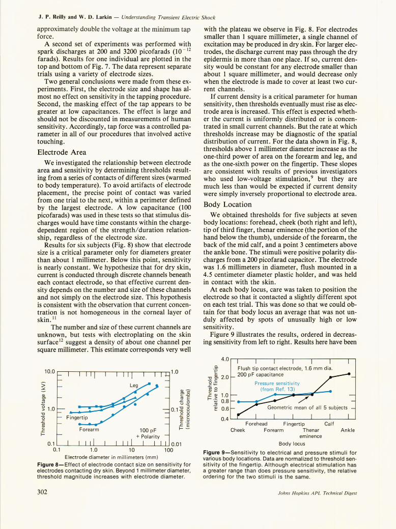
Electrode Area We investigated the relationship between electrode
area and sensitivity by determining thresholds resulting from a series of contacts of different sizes (warmed to body temperature). To avoid artifacts of electrode placement, the precise point of contact was varied from one trial to the next, within a perimeter defined by the largest electrode. A low capacitance (100 picofarads) was used in these tests so that stimulus discharges would have time constants within the chargedependent region of the strength/duration relationship, regardless of the electrode size.
Results for six subjects (Fig. 8) show that electrode size is a critical parameter only for diameters greater than about 1 millimeter. Below this point, sensitivity is nearly constant. We hypothesize that for dry skin, current is conducted through discrete channels beneath each contact electrode, so that effective current density depends on the number and size of these channels and not simply on the electrode size. This hypothesis is consistent with the observation that current concentration is not homogeneous in the corneal layer of skin. I I
The number and size of these current channels are unknown, but tests with electroplating on the skin surface 12 suggest a density of about one channel per square millimeter. This estimate corresponds very well
1 0.0 r---,---,--..--,-.-----,--.---..... ...-----.--r--,--,-, 1 .0
> .::£
QJ -
~.o ro E
£ 0 u_ "0 ::J
0.10 8 Fingertip
Forearm 100 pF + Polarity
£ 0 (I) 'QJ U
~ 'E 1--
0.1 '-----'-_"------'L-.L...L....-----'--_-'--.l.-..L....L..----L_....L...-....I.......LJ 0.01 0.1 1.0 10 100
Electrode d iameter in m illimeters (mm)
Figure 8-Effect of electrode contact s ize on sensitivity for electrodes contact ing dry skin. Beyond 1 mi l limeter diameter, threshold magnitude increases with electrode diameter.
302
with the plateau we observe in Fig. 8. For electrodes smaller than 1 square millimeter, a single channel of excitation may be produced in dry skin. For larger electrodes, the discharge current may pass through the dry epidermis in more than one place. If so, current density would be constant for any electrode smaller than about 1 square millimeter, and would decrease only when the electrode is made to cover at least two current channels.
If current density is a critical parameter for human sensitivity, then thresholds eventually must rise as electrode area is increased. This effect is expected whether the current is uniformly distributed or is concentrated in small current channels. But the rate at which thresholds increase may be diagnostic of the spatial distribution of current. For the data shown in Fig. 8, thresholds above 1 millimeter diameter increase as the one-third power of area on the forearm and leg, and as the one-sixth power on the fingertip. These slopes are consistent with results of previous investigators who used low-voltage stimulation,9 but they are much less than would be expected if current density were simply inversely proportional to electrode area.
Body Location We obtained thresholds for five subjects at seven
body locations: forehead, cheek (both right and left), tip of third finger, thenar eminence (the portion of the hand below the thumb), underside of the forearm, the back of the mid calf, and a point 3 centimeters above the ankle bone. The stimuli were positive polarity discharges from a 200 picofarad capacitor. The electrode was 1.6 millimeters in diameter, flush mounted in a 4.5 centimeter diameter plastic holder, and was held in contact with the skin.
At each body locus, care was taken to position the electrode so that it contacted a slightly different spot on each test trial. This was done so that we could obtain for that body locus an average that was not unduly affected by spots of unusually high or low sensitivity.
Figure 9 illustrates the results, ordered in decreasing sensitivity from left to right. Results here have been
4 .0~~-~-~~-~--~-~--~
a. ',j:;
"0 ~ 2.0 o ·~ £'+-
~B £ QJ 1.0 I- .~ 0.8
~ 0.6
Flush tip contact electrode, 1.6 mm dia. 200 pF capac itance
0.4 I......-''---_---'-__ '---_--L.. __ ..L..--_-L-__ ~
Forehead Fingertip Cal f Cheek Forearm Thenar Ank le
eminence
Body locus
Figure 9-Sensitivity to electrical and pressure stimuli for various body locations. Data are normalized to threshold sensitivity of the fingert ip. Although electrical stimulation has a greater range than does pressure sensitiv ity, t he relat ive ordering for the two stimuli is the same.
Johns Hopkins APL Technical Digest
J. P. Reilly and W. D. Larkin - Understanding Transient Electric Shock
normalized by the fingertip threshold for each subject. The fingertip was chosen for this purpose because it showed the smallest variability, both among and within subjects.
Five of the seven loci tested in the present experiment were included in Weinstein's study of cutaneous tactile stimuli in which he tested spatial discrimination and pressure sensitivity. 13 The rank ordering of our data is identical to his for pressure sensitivity, but not for spatial discrimination. Weinstein's normalized pressure sensitivity data are also shown in Fig. 9. Although the relative ordering is the same for the two types of stimulation, pressure sensitivity spans a range of about 1.6 to 1, whereas electrocutaneous sensitivity spans a range of over 4 to 1.
SUPRATHRESHOLD REACTIONS The determination of perception thresholds provides
a valuable but incomplete account of human sensitivity. It is also necessary to determine how sensation gains in strength at suprathreshold levels. Sensitivity measurements at levels above the threshold of detectability are important in defining the conditions under which people may be annoyed or disturbed by electrical currents. We present here results of psychophysical tests designed to measure sensitivity above threshold.
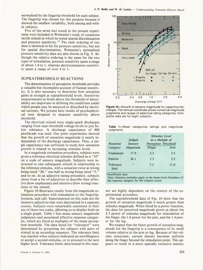
The electrical stimuli were single-spark discharges ranging from near-threshold voltage levels to just below tolerance. A discharge capacitance of 800 picofarads was used. Our prior experiments showed that the growth of sensation magnitude is nearly independent of the discharge capacitance. Thus, a single capacitance was sufficient to study how sensation growth is related to increasing stimulus levels.
In a magnitude estimation procedure, subjects were given a reference electrical stimulus defined as a "10" on a scale of sensory magnitude. Subjects were instructed to rate subsequent stimuli in relationship to the reference stimulus, with a sensation twice as strong being rated' '20," one-half as strong being rated" 5," and so on. In an adjective rating procedure, subjects chose from a list of adjectives to describe their affective (how unpleasant) and intensive (how strong) reactions to the stimuli.
Figure 1 0 illustrates results from the magnitude estimation procedure with stimulation to the fingertip, forearm, and calf. Superimposed on this scale are the intensive adjectives that were determined in a separate session. Subjects were remarkably consistent in their use of these two scales, allowing us to display both on a single graph. Table 1 lists mean sensory magnitude judgments and associated affective response categories, which are listed as multiples of the mean perception threshold. The data listed for "tolerance" were determined by presenting the subjects with pairs of stimuli in an ascending sequence. The tolerance limit was reached when subjects indicated an unwillingness to accept a second stimulus, or to proceed to the next higher level. Tolerance limits determined in this man-
Volume 5, Number 3, 1984
ClJ -0
.~ C OJ C1J
E >-~ c ClJ (/)
Moderate 10~ ______________ _
Weak
Very weak
+ Polarity - Polarity
800 pF : On finger On leg On arm
• •
• •
• •
0.1L-__ ~-L~~~~~------~--~~ 0.2 0.4 0.6 1.0 ' 2.0 4 .0
Discharge voltage (kV)
Figure 10-Growth of sensory magnitude for capacitive discharges. The vertical coordinate shows numerical magnitude judgments and ranges of adjectival rating categories. Composite data are for eight subjects.
Table 1-Mean categorical ratings and magnitude judgments.
Stimulus Level Judged as a Multiple of
Response Sensory Perception Threshold Category Magnitude Finger Arm
Unpleasant 17.9 2.3 3.5
Painful 26.1 3.5 5.5
Tolerance 7.1 11.0 limit
* Insufficient data Note: Stimulus multiples apply to the mean lower boundary of the response category for the' subjects tested.
ner are highly dependent on the context of the experimental procedure.
The suprathreshold data of Fig. 10 show that the growth of sensation magnitude is much greater than stimulus magnitude. When fitted by a power function, the data for perceived magnitude grows at about the 2.5 power of stimulus magnitude for stimulation of the finger, the 1.6 power for the arm, and the 1.4 power for the leg.
We suspect that the faster growth of sensation magnitude for the fingertip is a consequence of its small volume relative to the arm or leg. Because of the volume constraint, current density becomes uniform along the finger beyond the stimulation point. This appears to result in a more spatially extensive sensory
303
J. P. Reilly and W. D. Larkin - Understanding Transient Electric Shock
excitation; at suprathreshold levels, subjects report extended sensations along the finger.
The data in Table 1 show that the dynamic range for electrical stimulation is very small in relation to that for other sensory modalities. For electrical stimulation, a change of stimulus from perception to pain levels spans a range of only 3.5 to 1 or 5.5 to 1, depending on the locus of stimulation. We might contrast this range with that for hearing or pressure sensitivity, both of which have dynamic ranges over 100,000 to 1. We can thus appreciate the importance of perception threshold measurements in these sensory studies; if we can accurately measure the perception threshold, we know that a relatively small increase will result in a strong perceptual effect.
DISCUSSION
We have described several factors that influence sensitivity to transient electric currents. We have shown that an electrical model of neural excitation accounts very well for some of the observed effects. The neural excitation model relates threshold sensitivity to the duration of the stimulus, a relationship that depends on two parameters: the time duration, T, of the stimulus, and an experimentally determined time constant, T m ,
that represents the response time of the excitable neuron. A major conclusion is that sensitivity to very brief electrocutaneous pulses is governed by a different criterion than is sensitivity to long pulses. The sensory system appears to scale short-duration stimuli in units of charge and long-duration stimuli in units of current.
With capacitive discharge stimulation, the duration of the stimulus depends on the capacitance and on a variety of factors that affect skin impedance (such as voltage, electrode size, skin hydration, and the integrity of the corneal layer of the skin). Our experimental data on sensitivity, expressed as strength/duration curves (Fig. 6), fit well with the neural excitability model.
Such strength/duration relationships help explain the contour shapes of Fig. 5: constant charge contours result from procedures that maintain short stimulus time constants; procedures associated with long time constants result in curves that deviate from constant charge.
Other factors also affect sensitivity, even when the stimulus duration is maintained at a small value. The vertical displacements of the several curves in Fig. 5 result to a large extent from other factors that we have discussed in this article. In the tapping procedure, tactile masking elevates thresholds relative to those determined in the other procedures with a contact electrode. For the contact electrode procedures, a large electrode results in an elevated threshold relative to a small electrode because of current density effects. The subcutaneous electrode is also a small electrode. However, its threshold is reduced below that for the small electrode on the finger, in part because of the greater sensitivity of the forearm relative to the finger.
304
Even if all known variables are controlled or accounted for, we still observe significant variations in sensitivity from one person to another, or in the same individual measured at different times. In order to describe these variations, we are conducting trials with a large number of subjects. Some of our preliminary results show that body size affects sensitivity. As a result, women's thresholds average about 200/0 lower than men's for both perception and annoyance criteria, although individual differences in sensitivity can be as great as 3 to 1. While it may never be possible to understand thoroughly all the variables that account for human sensitivity to transient currents, a number of important variables have been systematically evaluated in our research.
REFERENCES FOR MAIN TEXT AND INSERT I J. P . Reilly, W. D. Larkin, R. J. Taylor, and V. T. Freeman, Human Reactions to Transient Electric Currents - Annual Report, July 1981 -June 1982, JHU / APL CPE-8203 (1982).
2J. P . Reilly, W. D. Larkin, R. J . Taylor, V. T. Freeman , and L. B. Kittler, Human Reactions to Transient Electric Currents - A nnual Report, July 1982 - June 1983, JHUlAPL CPE-8305 (1983).
3J. P . Reilly, W. D. Larkin, L. B. Kittler, and V. T. Freeman, Human Reactions to Transient Electric Currents - Annual Report, June 1983 -July 1984, JHU / APL CPE-8313 (1984).
4 J . P. Reilly and W. D. Larkin, "Electrocutaneous Stimulation with High Voltage Capacitive Discharges ," IEEE Trans. Biomed. Eng. 30, 631-641 (1983).
5 W. D. Larkin and J . P. Reilly, "Strength/ Duration Relationships for Electrocutaneous Sensitivity: Stimulation by Capacitive Discharges," in Perception and Psychophysics (in press).
6G. B. Rollman, " Behavioral Assessment of Peripheral erve Function," Neurology 25, 339-342 (1975).
7 J. F. Hahn , "Cutaneous Vibratory Thresholds for Square-Wave Electrical Pulses," Science 127, 879-880 (1958).
8 J. R. Heckmann , "Excitability Curve: A New Technique for Human Peripheral Nerve Excitability in Vivo," Neurology 22, 225-230 (1972) .
9 E. A. Pfeiffer, "Electrical Stimulation of Sensory Nerves with Skin Electrodes for Research Diagnosis, Communication and Behavioral Conditioning: A Survey," Med. BioI. Eng. 6, 637-651 (1968).
IO Y. T. Oester and S. H. Licht, " Routine Electrodiagnosis," in Electrodiagnosis and Electromyography, E. Licht Publisher , New Haven , pp. 201-217 (1971).
lIE. F. Mueller, R. Loeffel , and S. Mead, "Skin Impedance in Relation to Pain Threshold Testing by Electrical Means," 1. Appl. Phys. 5,746-752 (1953).
12 F. A. Saunders, "Electrocutaneous Displays," in Proc. Con! on Cutaneous Communication Systems and Devices, The Psychonomic Society, Austin, pp. 20-26 (1974).
13 S. Weinstein, "Intensive and Extensive Aspects of Tactile Sensitivity as a Function of Body Part , Sex, and Laterality," in The Skin Senses, C. Thomas, Springfield, III. , pp. 195-218 (1968).
RI D. R. McNeal, "Analysis of a Model of Excitation of Myelinated Nerve," IEEE Trans. Biomed. Eng. 23, 329-337 (1976).
R2B. Frankenhaeuser and A. F. Huxley, "The Action Potential in the Myelinated Nerve Fiber of Xenopus laevis as Computed on the Basis of Voltage Clamp Data," 1. Physiol. 171,302-3 15 (1964).
R3 R. Butikoffer and P . D. Lawrence, "Electrocutaneous Nerve Stimulation -I: Model and Experiment," IEEE Trans. Biomed. Eng. 25, 526-531 (1978).
R4 A. S. Paintal , "Conduction in Mammalian Nerve Fibers," in New Developments in Electromyography and Neurophysiology 2, Karger Publisher, Basel, Switzerland (1973).
R5 J . P . Reilly and W. D. Larkin, "Mechanisms for Human Sensitivity to Transient Electric Currents," in Proc. 1983 Symp. on Electrical Shock Safety Criteria, the Electric Power Research Institute and the Canadian Electrical Association (to be published, 1984).
ACKNOWLEDGMENT-This work was supported by the Maryland Power Plant Siting Program and the Canadian Electrical Association. We greatly appreciate the technical and analytical support of the other members of the research team: R. J. Taylor, L. B. Kittler, V. T. Freeman, and M. J. Flynn. We gratefully acknowledge the contributions of R. E. Rouse and T. F. Paraska, who designed and fabricated the stimulator.
Johns Hopkins A PL Technical Digest