Embed Size (px)
Citation preview
Understanding Wireless
Communications in Public
SafetyA Guidebook to
Technology, Issues,Planning, and Management
National Law Enforcement andCorrections Technology Center
National Law Enforcement and Corrections Technology Center
Understanding WirelessCommunications in Public Safety
A Guidebook to Technology, Issues, Planning, andManagement
Written by: Kathy J. Imel and James W. Hart, P.E.
For:The National Law Enforcement and Corrections Technology Center (Rocky MountainRegion)A Program of the National Institute of Justice
March 2000Revised: August 2000
National Institute of Justice
Julie E. SamuelsActing Director
NCJ 180211
The National Law Enforcement and Corrections Technology Center is supported by CooperativeAgreement #96–MU–MU–K011 awarded by the U.S. Department of Justice, Office of Justice Programs,National Institute of Justice. Analyses of test results do not represent product approval or endorsement bythe National Institute of Justice, U.S. Department of Justice; the National Institute of Standards andTechnology, U.S. Department of Commerce; or Aspen Systems Corporation. Points of view or opinionscontained within this document are those of the authors and do not necessarily represent the officialposition of the U.S. Department of Justice.
The National Institute of Justice is a component of the Office of Justice Programs, which also includes theBureau of Justice Assistance, Bureau of Justice Statistics, Office of Juvenile Justice and DelinquencyPrevention, and Office for Victims of Crime.
Table of Contents
-iii-
TABLE OF CONTENTS
The National Law Enforcement and Corrections Technology Center–Rocky Mountain . . . . . . . . . ix
Acknowledgments . . . . . . . . . . . . . . . . . . . . . . . . . . . . . . . . . . . . . . . . . . . . . . . . . . . . . . . . . . . . . . . ix
Introduction . . . . . . . . . . . . . . . . . . . . . . . . . . . . . . . . . . . . . . . . . . . . . . . . . . . . . . . . . . . . . . . . . . . . . 1
Part 1. Planning and Managing a Communications Project . . . . . . . . . . . . . . . . . . . . . . . . . . . . . . . . 3
Chapter 1. What It Takes to Succeed . . . . . . . . . . . . . . . . . . . . . . . . . . . . . . . . . . . . . . . . . . . . . . 5A Plan . . . . . . . . . . . . . . . . . . . . . . . . . . . . . . . . . . . . . . . . . . . . . . . . . . . . . . . . . . . . . . . . . . . . 5Time, Money, and Resources . . . . . . . . . . . . . . . . . . . . . . . . . . . . . . . . . . . . . . . . . . . . . . . . . . . 5Getting Started . . . . . . . . . . . . . . . . . . . . . . . . . . . . . . . . . . . . . . . . . . . . . . . . . . . . . . . . . . . . . 6
What Do You Have Now? . . . . . . . . . . . . . . . . . . . . . . . . . . . . . . . . . . . . . . . . . . . . . . . . . . 6What Do You Need? . . . . . . . . . . . . . . . . . . . . . . . . . . . . . . . . . . . . . . . . . . . . . . . . . . . . . . 7What Are Your Options? . . . . . . . . . . . . . . . . . . . . . . . . . . . . . . . . . . . . . . . . . . . . . . . . . . . 7How Much Will It Cost? . . . . . . . . . . . . . . . . . . . . . . . . . . . . . . . . . . . . . . . . . . . . . . . . . . . 8How Do You Implement the Project? . . . . . . . . . . . . . . . . . . . . . . . . . . . . . . . . . . . . . . . . . . 9
Getting Help . . . . . . . . . . . . . . . . . . . . . . . . . . . . . . . . . . . . . . . . . . . . . . . . . . . . . . . . . . . . . . . 9Other Agencies . . . . . . . . . . . . . . . . . . . . . . . . . . . . . . . . . . . . . . . . . . . . . . . . . . . . . . . . . . 9Consultants . . . . . . . . . . . . . . . . . . . . . . . . . . . . . . . . . . . . . . . . . . . . . . . . . . . . . . . . . . . . . 9Vendors . . . . . . . . . . . . . . . . . . . . . . . . . . . . . . . . . . . . . . . . . . . . . . . . . . . . . . . . . . . . . . 10
Chapter 2. Planning the Project . . . . . . . . . . . . . . . . . . . . . . . . . . . . . . . . . . . . . . . . . . . . . . . . . . 11Realistic Schedule . . . . . . . . . . . . . . . . . . . . . . . . . . . . . . . . . . . . . . . . . . . . . . . . . . . . . . . . . . 11Project Team(s) . . . . . . . . . . . . . . . . . . . . . . . . . . . . . . . . . . . . . . . . . . . . . . . . . . . . . . . . . . . . 11
Project Manager . . . . . . . . . . . . . . . . . . . . . . . . . . . . . . . . . . . . . . . . . . . . . . . . . . . . . . . . 12Responsibility . . . . . . . . . . . . . . . . . . . . . . . . . . . . . . . . . . . . . . . . . . . . . . . . . . . . . . . 12Authority . . . . . . . . . . . . . . . . . . . . . . . . . . . . . . . . . . . . . . . . . . . . . . . . . . . . . . . . . . 12Time . . . . . . . . . . . . . . . . . . . . . . . . . . . . . . . . . . . . . . . . . . . . . . . . . . . . . . . . . . . . . . 12Management Support . . . . . . . . . . . . . . . . . . . . . . . . . . . . . . . . . . . . . . . . . . . . . . . . . 12Physical Resources . . . . . . . . . . . . . . . . . . . . . . . . . . . . . . . . . . . . . . . . . . . . . . . . . . . 12
Other Team Members . . . . . . . . . . . . . . . . . . . . . . . . . . . . . . . . . . . . . . . . . . . . . . . . . . . . 12Budget . . . . . . . . . . . . . . . . . . . . . . . . . . . . . . . . . . . . . . . . . . . . . . . . . . . . . . . . . . . . . . . . . . 13
Chapter 3. Obtaining Funds . . . . . . . . . . . . . . . . . . . . . . . . . . . . . . . . . . . . . . . . . . . . . . . . . . . . 15Types of Funds . . . . . . . . . . . . . . . . . . . . . . . . . . . . . . . . . . . . . . . . . . . . . . . . . . . . . . . . . . . . 15Sources of Funds . . . . . . . . . . . . . . . . . . . . . . . . . . . . . . . . . . . . . . . . . . . . . . . . . . . . . . . . . . . 15
Federal Sources . . . . . . . . . . . . . . . . . . . . . . . . . . . . . . . . . . . . . . . . . . . . . . . . . . . . . . . . . 15
-iv-
Block Grants . . . . . . . . . . . . . . . . . . . . . . . . . . . . . . . . . . . . . . . . . . . . . . . . . . . . . . . 17Discretionary Grants . . . . . . . . . . . . . . . . . . . . . . . . . . . . . . . . . . . . . . . . . . . . . . . . . . 17Federal Asset Forfeiture Funds . . . . . . . . . . . . . . . . . . . . . . . . . . . . . . . . . . . . . . . . . . 17
State Sources . . . . . . . . . . . . . . . . . . . . . . . . . . . . . . . . . . . . . . . . . . . . . . . . . . . . . . . . . . 18Local Sources . . . . . . . . . . . . . . . . . . . . . . . . . . . . . . . . . . . . . . . . . . . . . . . . . . . . . . . . . . 18
Single Agency Versus Multiple Agencies . . . . . . . . . . . . . . . . . . . . . . . . . . . . . . . . . . . 19“Selling” Your Need . . . . . . . . . . . . . . . . . . . . . . . . . . . . . . . . . . . . . . . . . . . . . . . . . . . . . . . . 19Getting Help . . . . . . . . . . . . . . . . . . . . . . . . . . . . . . . . . . . . . . . . . . . . . . . . . . . . . . . . . . . . . . 20
Chapter 4. Buying What You Need . . . . . . . . . . . . . . . . . . . . . . . . . . . . . . . . . . . . . . . . . . . . . . . 23How to Buy . . . . . . . . . . . . . . . . . . . . . . . . . . . . . . . . . . . . . . . . . . . . . . . . . . . . . . . . . . . . . . . 23
Competitive Procurement . . . . . . . . . . . . . . . . . . . . . . . . . . . . . . . . . . . . . . . . . . . . . . . . . 23Noncompetitive Procurement . . . . . . . . . . . . . . . . . . . . . . . . . . . . . . . . . . . . . . . . . . . . . . . 23
Sole Source Procurement . . . . . . . . . . . . . . . . . . . . . . . . . . . . . . . . . . . . . . . . . . . . . . 24Contract for Operational Services . . . . . . . . . . . . . . . . . . . . . . . . . . . . . . . . . . . . . . . . 24
Cooperative Purchasing . . . . . . . . . . . . . . . . . . . . . . . . . . . . . . . . . . . . . . . . . . . . . . . . . . . 24Leasing . . . . . . . . . . . . . . . . . . . . . . . . . . . . . . . . . . . . . . . . . . . . . . . . . . . . . . . . . . . . . . . 25Outsourcing . . . . . . . . . . . . . . . . . . . . . . . . . . . . . . . . . . . . . . . . . . . . . . . . . . . . . . . . . . . 25Request for Information (RFI) . . . . . . . . . . . . . . . . . . . . . . . . . . . . . . . . . . . . . . . . . . . . . . 25
Competitive Procurement (RFP) . . . . . . . . . . . . . . . . . . . . . . . . . . . . . . . . . . . . . . . . . . . . . . . 26Request for Proposal (RFP) . . . . . . . . . . . . . . . . . . . . . . . . . . . . . . . . . . . . . . . . . . . . . . . . 26RFP Process . . . . . . . . . . . . . . . . . . . . . . . . . . . . . . . . . . . . . . . . . . . . . . . . . . . . . . . . . . . 26
Develop the RFP . . . . . . . . . . . . . . . . . . . . . . . . . . . . . . . . . . . . . . . . . . . . . . . . . . . . . 26Issue the RFP . . . . . . . . . . . . . . . . . . . . . . . . . . . . . . . . . . . . . . . . . . . . . . . . . . . . . . . 27Evaluate Responses . . . . . . . . . . . . . . . . . . . . . . . . . . . . . . . . . . . . . . . . . . . . . . . . . . 28Select Vendor . . . . . . . . . . . . . . . . . . . . . . . . . . . . . . . . . . . . . . . . . . . . . . . . . . . . . . . 28Negotiate Contract . . . . . . . . . . . . . . . . . . . . . . . . . . . . . . . . . . . . . . . . . . . . . . . . . . . 29Manage the Project . . . . . . . . . . . . . . . . . . . . . . . . . . . . . . . . . . . . . . . . . . . . . . . . . . . 30Acceptance Testing . . . . . . . . . . . . . . . . . . . . . . . . . . . . . . . . . . . . . . . . . . . . . . . . . . . 30
Part 2. Wireless Communications Technology . . . . . . . . . . . . . . . . . . . . . . . . . . . . . . . . . . . . . . . . . 31
Chapter 5. Voice Versus Data . . . . . . . . . . . . . . . . . . . . . . . . . . . . . . . . . . . . . . . . . . . . . . . . . . . 33Voice Versus Data . . . . . . . . . . . . . . . . . . . . . . . . . . . . . . . . . . . . . . . . . . . . . . . . . . . . . . . . . 33Analog Versus Digital . . . . . . . . . . . . . . . . . . . . . . . . . . . . . . . . . . . . . . . . . . . . . . . . . . . . . . . 34
Analog Radio Systems . . . . . . . . . . . . . . . . . . . . . . . . . . . . . . . . . . . . . . . . . . . . . . . . . . . 35Digital Radio Systems . . . . . . . . . . . . . . . . . . . . . . . . . . . . . . . . . . . . . . . . . . . . . . . . . . . . 35Transmission Differences . . . . . . . . . . . . . . . . . . . . . . . . . . . . . . . . . . . . . . . . . . . . . . . . . 36
Chapter 6. Characteristics of Radio Systems . . . . . . . . . . . . . . . . . . . . . . . . . . . . . . . . . . . . . . . 39Understanding Radio Terms . . . . . . . . . . . . . . . . . . . . . . . . . . . . . . . . . . . . . . . . . . . . . . . . . . 39
Wave . . . . . . . . . . . . . . . . . . . . . . . . . . . . . . . . . . . . . . . . . . . . . . . . . . . . . . . . . . . . . . . . 39Wavelength . . . . . . . . . . . . . . . . . . . . . . . . . . . . . . . . . . . . . . . . . . . . . . . . . . . . . . . . . . . . 40Cycle . . . . . . . . . . . . . . . . . . . . . . . . . . . . . . . . . . . . . . . . . . . . . . . . . . . . . . . . . . . . . . . . 40Frequency . . . . . . . . . . . . . . . . . . . . . . . . . . . . . . . . . . . . . . . . . . . . . . . . . . . . . . . . . . . . . 40
Table of Contents
-v-
Spectrum and Bands . . . . . . . . . . . . . . . . . . . . . . . . . . . . . . . . . . . . . . . . . . . . . . . . . . . . . 41Public Safety Bands . . . . . . . . . . . . . . . . . . . . . . . . . . . . . . . . . . . . . . . . . . . . . . . . . . 42
Channels . . . . . . . . . . . . . . . . . . . . . . . . . . . . . . . . . . . . . . . . . . . . . . . . . . . . . . . . . . . . . . 42Mobile Radio System Frequencies . . . . . . . . . . . . . . . . . . . . . . . . . . . . . . . . . . . . . . . . . . . . . . 44
Frequency Selection Considerations . . . . . . . . . . . . . . . . . . . . . . . . . . . . . . . . . . . . . . . . . . 44Coverage . . . . . . . . . . . . . . . . . . . . . . . . . . . . . . . . . . . . . . . . . . . . . . . . . . . . . . . . . . 44Building Penetration . . . . . . . . . . . . . . . . . . . . . . . . . . . . . . . . . . . . . . . . . . . . . . . . . . 44Skip . . . . . . . . . . . . . . . . . . . . . . . . . . . . . . . . . . . . . . . . . . . . . . . . . . . . . . . . . . . . . . 44Noise . . . . . . . . . . . . . . . . . . . . . . . . . . . . . . . . . . . . . . . . . . . . . . . . . . . . . . . . . . . . . 44Antenna Size . . . . . . . . . . . . . . . . . . . . . . . . . . . . . . . . . . . . . . . . . . . . . . . . . . . . . . . . 44
Transmitters and Receivers . . . . . . . . . . . . . . . . . . . . . . . . . . . . . . . . . . . . . . . . . . . . . . . . . . . 45Transmitters . . . . . . . . . . . . . . . . . . . . . . . . . . . . . . . . . . . . . . . . . . . . . . . . . . . . . . . . . . . 45Receivers . . . . . . . . . . . . . . . . . . . . . . . . . . . . . . . . . . . . . . . . . . . . . . . . . . . . . . . . . . . . . 46
Antennas . . . . . . . . . . . . . . . . . . . . . . . . . . . . . . . . . . . . . . . . . . . . . . . . . . . . . . . . . . . . . . . . . 47Gain . . . . . . . . . . . . . . . . . . . . . . . . . . . . . . . . . . . . . . . . . . . . . . . . . . . . . . . . . . . . . . . . . 47Types of Antennas . . . . . . . . . . . . . . . . . . . . . . . . . . . . . . . . . . . . . . . . . . . . . . . . . . . . . . 49
Base Station Antennas . . . . . . . . . . . . . . . . . . . . . . . . . . . . . . . . . . . . . . . . . . . . . . . . 49Directional Antennas . . . . . . . . . . . . . . . . . . . . . . . . . . . . . . . . . . . . . . . . . . . . . . . . . . 49Mobile Antennas . . . . . . . . . . . . . . . . . . . . . . . . . . . . . . . . . . . . . . . . . . . . . . . . . . . . . 50Portable Antennas . . . . . . . . . . . . . . . . . . . . . . . . . . . . . . . . . . . . . . . . . . . . . . . . . . . . 50Smart Antennas . . . . . . . . . . . . . . . . . . . . . . . . . . . . . . . . . . . . . . . . . . . . . . . . . . . . . 50
Interference . . . . . . . . . . . . . . . . . . . . . . . . . . . . . . . . . . . . . . . . . . . . . . . . . . . . . . . . . . . . 50Radiation . . . . . . . . . . . . . . . . . . . . . . . . . . . . . . . . . . . . . . . . . . . . . . . . . . . . . . . . . . . . . 51Local Regulations Controlling Antennas . . . . . . . . . . . . . . . . . . . . . . . . . . . . . . . . . . . . . . 51
Radio Coverage . . . . . . . . . . . . . . . . . . . . . . . . . . . . . . . . . . . . . . . . . . . . . . . . . . . . . . . . . . . . 51Duplexers, Combiners, Multicouplers . . . . . . . . . . . . . . . . . . . . . . . . . . . . . . . . . . . . . . . . . . . 53
Duplexers . . . . . . . . . . . . . . . . . . . . . . . . . . . . . . . . . . . . . . . . . . . . . . . . . . . . . . . . . . . . . 53Combiners . . . . . . . . . . . . . . . . . . . . . . . . . . . . . . . . . . . . . . . . . . . . . . . . . . . . . . . . . . . . 54Multicouplers . . . . . . . . . . . . . . . . . . . . . . . . . . . . . . . . . . . . . . . . . . . . . . . . . . . . . . . . . . 55
Multiple Access Systems . . . . . . . . . . . . . . . . . . . . . . . . . . . . . . . . . . . . . . . . . . . . . . . . . . . . . 56Frequency Division Multiple Access (FDMA) . . . . . . . . . . . . . . . . . . . . . . . . . . . . . . . . . . 56Time Division Multiple Access (TDMA) . . . . . . . . . . . . . . . . . . . . . . . . . . . . . . . . . . . . . . 56Code Division Multiple Access (CDMA) . . . . . . . . . . . . . . . . . . . . . . . . . . . . . . . . . . . . . . 57
Frequency Hopping . . . . . . . . . . . . . . . . . . . . . . . . . . . . . . . . . . . . . . . . . . . . . . . . . . . 57Direct Sequence . . . . . . . . . . . . . . . . . . . . . . . . . . . . . . . . . . . . . . . . . . . . . . . . . . . . . 57
Packaging Data . . . . . . . . . . . . . . . . . . . . . . . . . . . . . . . . . . . . . . . . . . . . . . . . . . . . . . . . . . . 57
Chapter 7. Current Public Safety Radio Systems . . . . . . . . . . . . . . . . . . . . . . . . . . . . . . . . . . . . 59Paging Systems . . . . . . . . . . . . . . . . . . . . . . . . . . . . . . . . . . . . . . . . . . . . . . . . . . . . . . . . . . . . 59Two-Way Simplex Radio Systems . . . . . . . . . . . . . . . . . . . . . . . . . . . . . . . . . . . . . . . . . . . . . . 60Two-Way Mobile Relay Systems . . . . . . . . . . . . . . . . . . . . . . . . . . . . . . . . . . . . . . . . . . . . . . . 60
Repeater Innovations . . . . . . . . . . . . . . . . . . . . . . . . . . . . . . . . . . . . . . . . . . . . . . . . . . . . . 61Mobile Repeaters . . . . . . . . . . . . . . . . . . . . . . . . . . . . . . . . . . . . . . . . . . . . . . . . . . . . . . . 62
Trunked Radio Systems . . . . . . . . . . . . . . . . . . . . . . . . . . . . . . . . . . . . . . . . . . . . . . . . . . . . . . 63Specialized Mobile Radio (SMR) . . . . . . . . . . . . . . . . . . . . . . . . . . . . . . . . . . . . . . . . . . . 65
-vi-
APCO Project 16 Trunked Radio System . . . . . . . . . . . . . . . . . . . . . . . . . . . . . . . . . . . . . 65APCO Project 25 Digital Trunked Radio System . . . . . . . . . . . . . . . . . . . . . . . . . . . . . . . . 66
220 MHz Narrow Bandwidth Band . . . . . . . . . . . . . . . . . . . . . . . . . . . . . . . . . . . . . . . . . . . . . 67TErrestrial TRunked RAdio (TETRA) . . . . . . . . . . . . . . . . . . . . . . . . . . . . . . . . . . . . . . . . . . . 67Cellular Radio/Telephone Systems . . . . . . . . . . . . . . . . . . . . . . . . . . . . . . . . . . . . . . . . . . . . . . 68Personal Communications Systems (PCS) . . . . . . . . . . . . . . . . . . . . . . . . . . . . . . . . . . . . . . . . 70Cellular Digital Packet Data . . . . . . . . . . . . . . . . . . . . . . . . . . . . . . . . . . . . . . . . . . . . . . . . . . 71Point-To-Point Microwave Communications Systems . . . . . . . . . . . . . . . . . . . . . . . . . . . . . . . 71
Licensing . . . . . . . . . . . . . . . . . . . . . . . . . . . . . . . . . . . . . . . . . . . . . . . . . . . . . . . . . . . . . 72
Part 3. Wireless Communications Issues . . . . . . . . . . . . . . . . . . . . . . . . . . . . . . . . . . . . . . . . . . . . . . 73
Chapter 8. FCC Licensing, Rules, Regulations, and Related Issues . . . . . . . . . . . . . . . . . . . . . . 75Licensing . . . . . . . . . . . . . . . . . . . . . . . . . . . . . . . . . . . . . . . . . . . . . . . . . . . . . . . . . . . . . . . . 75FCC Rules and Regulations . . . . . . . . . . . . . . . . . . . . . . . . . . . . . . . . . . . . . . . . . . . . . . . . . . . 76
Part 90 . . . . . . . . . . . . . . . . . . . . . . . . . . . . . . . . . . . . . . . . . . . . . . . . . . . . . . . . . . . . . . . 76Docket 92-335 . . . . . . . . . . . . . . . . . . . . . . . . . . . . . . . . . . . . . . . . . . . . . . . . . . . . . . 76
Part 22 . . . . . . . . . . . . . . . . . . . . . . . . . . . . . . . . . . . . . . . . . . . . . . . . . . . . . . . . . . . . . . . 76Part 24 . . . . . . . . . . . . . . . . . . . . . . . . . . . . . . . . . . . . . . . . . . . . . . . . . . . . . . . . . . . . . . . 77Part 101 . . . . . . . . . . . . . . . . . . . . . . . . . . . . . . . . . . . . . . . . . . . . . . . . . . . . . . . . . . . . . . 77
Frequency Reallocation . . . . . . . . . . . . . . . . . . . . . . . . . . . . . . . . . . . . . . . . . . . . . . . . . . . . . . 77Refarming . . . . . . . . . . . . . . . . . . . . . . . . . . . . . . . . . . . . . . . . . . . . . . . . . . . . . . . . . . . . . . . . 78
Chapter 9. Radiofrequency Electromagnetic Radiation Exposure . . . . . . . . . . . . . . . . . . . . . . . 79
Chapter 10. FBI NCIC 2000 . . . . . . . . . . . . . . . . . . . . . . . . . . . . . . . . . . . . . . . . . . . . . . . . . . . . 81
Part 4. Wireless Communications Options . . . . . . . . . . . . . . . . . . . . . . . . . . . . . . . . . . . . . . . . . . . . 83
Chapter 11. Voice Systems . . . . . . . . . . . . . . . . . . . . . . . . . . . . . . . . . . . . . . . . . . . . . . . . . . . . . 85Dedicated Radio Systems . . . . . . . . . . . . . . . . . . . . . . . . . . . . . . . . . . . . . . . . . . . . . . . . . . . . 85
Sample Vendors . . . . . . . . . . . . . . . . . . . . . . . . . . . . . . . . . . . . . . . . . . . . . . . . . . . . . . . . 85Motorola, Inc. . . . . . . . . . . . . . . . . . . . . . . . . . . . . . . . . . . . . . . . . . . . . . . . . . . . . . . . 85ComNet Ericsson Critical Radio Systems. . . . . . . . . . . . . . . . . . . . . . . . . . . . . . . . . . . 86E.F. Johnson Division of Transcrypt. . . . . . . . . . . . . . . . . . . . . . . . . . . . . . . . . . . . . . 86
Advantages of Dedicated Systems . . . . . . . . . . . . . . . . . . . . . . . . . . . . . . . . . . . . . . . . . . . 87Disadvantages of Dedicated Systems . . . . . . . . . . . . . . . . . . . . . . . . . . . . . . . . . . . . . . . . . 87
Cellular and PCS Radio . . . . . . . . . . . . . . . . . . . . . . . . . . . . . . . . . . . . . . . . . . . . . . . . . . . . . . 87System Coverage . . . . . . . . . . . . . . . . . . . . . . . . . . . . . . . . . . . . . . . . . . . . . . . . . . . . . . . 87Pricing . . . . . . . . . . . . . . . . . . . . . . . . . . . . . . . . . . . . . . . . . . . . . . . . . . . . . . . . . . . . . . . 87Sample Vendors . . . . . . . . . . . . . . . . . . . . . . . . . . . . . . . . . . . . . . . . . . . . . . . . . . . . . . . . 88
AT&T Wireless Services. . . . . . . . . . . . . . . . . . . . . . . . . . . . . . . . . . . . . . . . . . . . . . . 88Sprint. . . . . . . . . . . . . . . . . . . . . . . . . . . . . . . . . . . . . . . . . . . . . . . . . . . . . . . . . . . . . 88
Advantages of Cellular/PCS Radio . . . . . . . . . . . . . . . . . . . . . . . . . . . . . . . . . . . . . . . . . . 88Disadvantages of Cellular/PCS Radio . . . . . . . . . . . . . . . . . . . . . . . . . . . . . . . . . . . . . . . . 88
Table of Contents
-vii-
A Special Case: Conventional Radio System for the Township of Upper St. Clair,Pennsylvania . . . . . . . . . . . . . . . . . . . . . . . . . . . . . . . . . . . . . . . . . . . . . . . . . . . . . . . . . . . 89
Voice—SMR/ESMR . . . . . . . . . . . . . . . . . . . . . . . . . . . . . . . . . . . . . . . . . . . . . . . . . . . . . . . . 89Sample Vendor—Nextel . . . . . . . . . . . . . . . . . . . . . . . . . . . . . . . . . . . . . . . . . . . . . . . . . . 90
Services . . . . . . . . . . . . . . . . . . . . . . . . . . . . . . . . . . . . . . . . . . . . . . . . . . . . . . . . . . . 90System Coverage . . . . . . . . . . . . . . . . . . . . . . . . . . . . . . . . . . . . . . . . . . . . . . . . . . . . 91Pricing . . . . . . . . . . . . . . . . . . . . . . . . . . . . . . . . . . . . . . . . . . . . . . . . . . . . . . . . . . . . 91
Sample Vendor—Lower Colorado River Authority . . . . . . . . . . . . . . . . . . . . . . . . . . . . . . 92Advantages of an SMR/ESMR System . . . . . . . . . . . . . . . . . . . . . . . . . . . . . . . . . . . . . . . 92Disadvantages of an SMR/ESMR System . . . . . . . . . . . . . . . . . . . . . . . . . . . . . . . . . . . . . 92
Chapter 12. Wireless Data Systems . . . . . . . . . . . . . . . . . . . . . . . . . . . . . . . . . . . . . . . . . . . . . . . 93Cellular Digital Packet Data (CDPD) . . . . . . . . . . . . . . . . . . . . . . . . . . . . . . . . . . . . . . . . . . . 93
Sample Vendors . . . . . . . . . . . . . . . . . . . . . . . . . . . . . . . . . . . . . . . . . . . . . . . . . . . . . . . . 93AT&T Wireless . . . . . . . . . . . . . . . . . . . . . . . . . . . . . . . . . . . . . . . . . . . . . . . . . . . . . 93Bell Atlantic Mobile . . . . . . . . . . . . . . . . . . . . . . . . . . . . . . . . . . . . . . . . . . . . . . . . . . 94GTE Wireless . . . . . . . . . . . . . . . . . . . . . . . . . . . . . . . . . . . . . . . . . . . . . . . . . . . . . . . 94
Advantages of CDPD . . . . . . . . . . . . . . . . . . . . . . . . . . . . . . . . . . . . . . . . . . . . . . . . . . . . 94Disadvantages of CDPD . . . . . . . . . . . . . . . . . . . . . . . . . . . . . . . . . . . . . . . . . . . . . . . . . . 95
Private National Data Networks . . . . . . . . . . . . . . . . . . . . . . . . . . . . . . . . . . . . . . . . . . . . . . . 95Sample Vendors . . . . . . . . . . . . . . . . . . . . . . . . . . . . . . . . . . . . . . . . . . . . . . . . . . . . . . . . 95
Motient Wireless Data Network . . . . . . . . . . . . . . . . . . . . . . . . . . . . . . . . . . . . . . . . . 95BellSouth Mobile Data (RAM Network) . . . . . . . . . . . . . . . . . . . . . . . . . . . . . . . . . . . 96
Advantages of Private National Data Networks . . . . . . . . . . . . . . . . . . . . . . . . . . . . . . . . . 97Disadvantages of Private National Data Networks . . . . . . . . . . . . . . . . . . . . . . . . . . . . . . . 97
Regional Voice and Data Systems . . . . . . . . . . . . . . . . . . . . . . . . . . . . . . . . . . . . . . . . . . . . . . 98Sample Vendor . . . . . . . . . . . . . . . . . . . . . . . . . . . . . . . . . . . . . . . . . . . . . . . . . . . . . . . . . 98
Racom . . . . . . . . . . . . . . . . . . . . . . . . . . . . . . . . . . . . . . . . . . . . . . . . . . . . . . . . . . . . 98Advantages of Regional Voice and Data Systems . . . . . . . . . . . . . . . . . . . . . . . . . . . . . . . . 99Disadvantages of Regional Voice and Data Systems . . . . . . . . . . . . . . . . . . . . . . . . . . . . . 99
Chapter 13. Latest Developments . . . . . . . . . . . . . . . . . . . . . . . . . . . . . . . . . . . . . . . . . . . . . . . 101Mobile Satellites . . . . . . . . . . . . . . . . . . . . . . . . . . . . . . . . . . . . . . . . . . . . . . . . . . . . . . . . . . 101
Voice Communications Satellites . . . . . . . . . . . . . . . . . . . . . . . . . . . . . . . . . . . . . . . . . . . 101Example System—Iridium . . . . . . . . . . . . . . . . . . . . . . . . . . . . . . . . . . . . . . . . . . . . 102Other Voice Satellite Systems . . . . . . . . . . . . . . . . . . . . . . . . . . . . . . . . . . . . . . . . . . 105
Data Communications Satellites . . . . . . . . . . . . . . . . . . . . . . . . . . . . . . . . . . . . . . . . . . . 106High Altitude Long Endurance (HALE) Platforms . . . . . . . . . . . . . . . . . . . . . . . . . . . . . . . . . 107
Summary . . . . . . . . . . . . . . . . . . . . . . . . . . . . . . . . . . . . . . . . . . . . . . . . . . . . . . . . . . . . . . . . . . . . . 109
Glossary and Acronyms . . . . . . . . . . . . . . . . . . . . . . . . . . . . . . . . . . . . . . . . . . . . . . . . . . . . . . . . . . 111Glossary . . . . . . . . . . . . . . . . . . . . . . . . . . . . . . . . . . . . . . . . . . . . . . . . . . . . . . . . . . . . . . . . . . . 113Acronyms . . . . . . . . . . . . . . . . . . . . . . . . . . . . . . . . . . . . . . . . . . . . . . . . . . . . . . . . . . . . . . . . . . 117

-viii-
Appendixes . . . . . . . . . . . . . . . . . . . . . . . . . . . . . . . . . . . . . . . . . . . . . . . . . . . . . . . . . . . . . . . . . . . . 119Appendix A. State Agencies Administering Byrne Program Grants . . . . . . . . . . . . . . . . . . . . . . . . 121Appendix B. NTIA State Single Point-of-Contact List . . . . . . . . . . . . . . . . . . . . . . . . . . . . . . . . . 123Appendix C. APCO Local Frequency Advisers . . . . . . . . . . . . . . . . . . . . . . . . . . . . . . . . . . . . . . 125Appendix D. Resources . . . . . . . . . . . . . . . . . . . . . . . . . . . . . . . . . . . . . . . . . . . . . . . . . . . . . . . . 133
-ix-
The National Law Enforcement and Corrections TechnologyCenter–Rocky Mountain
The National Law Enforcement and Corrections Technology Center (NLECTC) system was created in1994 as a component of the National Institute of Justice’s (NIJ’s) Office of Science and Technology.NLECTC’s goal, like that of NIJ, is to offer support, research findings, and technological expertise to helpState and local public safety personnel do their jobs safely and efficiently.
NIJ’s NLECTC system consists of facilities located across the country that are colocated with anorganization or agency that specializes in one or more specific areas of research and development.Although each of the NLECTC facilities has a different technology focus, they work together to form aseamless web of support, technology development, and information to help the public safety community.
Located at the University of Denver, NLECTC–Rocky Mountain focuses on communicationsinteroperability and the difficulties that often occur when different agencies and jurisdictions try tocommunicate with one another. This facility works with public safety agencies, private industry, andnational organizations to implement projects that will identify and field test new technologies to help solvethe problems of interoperability. NLECTC–Rocky Mountain also houses the newly created Crime MappingTechnology Center, the training and practical application arm of NIJ’s Crime Mapping Research Center.The Rocky Mountain facility also conducts research into ballistics and weapons technology, as well asinformation systems.
Acknowledgments
The authors wish to acknowledge and thank the following individuals and organizations for their invaluableguidance and assistance in the preparation of this guidebook:
The staff at NLECTC–Rocky Mountain: Thomas Tolman, who conceived the idea and managed theproject; Robert Epper, who found the funding; and Gene McGahey, who inherited the product to finish.Also many thanks to Joni Morris, for great graphics, and Courtney Klug, for tracking down everything weever needed.
For providing background information and materials: Patrick Hobby and Barb May (Motorola), StephenRuskin (Ericsson), Robert Kuch (Nextel), Doug Daniels (AT&T Wireless), Larry Krenek (LCRA), MarkMinnick (San Marcos PD), and Gregg Miller (RACOM).
Our local advisory panel, whose suggestions made a world of difference: Scott Snyder (Longmont Fire),Terri Thornberry (Durango/La Plata Communications), Frank Bishop (Greeley/Weld Communications),Mary Moore (Fort Collins Police), Mike Borrego (State of Colorado Telecommunications), Scott Morrill(Gunnison Communications), Ed Connors (Denver Police), and Emery Reynolds (Arapahoe CountySheriff’s Department).
-x-
Author Contacts:
Kathy J. Imel James W. Hart, P.E. La Loba International, Inc. Hartech, Inc.(p): 303–438–9565 (p): 303–795–2813(f): 303–438–1244 (f): 303–347–2652E-mail: [email protected] E-mail: [email protected]
NLECTC–RM Contacts:
Tom Tolman Gene McGahey(p): 303–871–4190 (p): 303–871–7453(f): 303–871–2500 (f): 303–871–2500E-mail: [email protected] E-mail: [email protected]
To order additional copies of this document, please call NLECTC at 800–248–2742, or download a copyfrom the World Wide Web site at www.nlectc.org.
-1-
INTRODUCTION
The National Law Enforcement and Corrections Technology Center (NLECTC) system was conceivedwith the idea of helping public safety personnel understand and use new technology. In keeping with thatgoal, NLECTC–Rocky Mountain developed this guidebook to help unravel the confusing issues, terms, andoptions surrounding wireless communications, particularly as it involves commercially availablecommunications services.
The target audience consists of those middle and upper managers who are responsible for funding and/ormanaging communications at their agencies, but who have little or no technical background in wirelesstechnology.
This guidebook is divided into four parts:
Part 1. Planning and Managing a Communications Project: Discusses the overall scope of aproject, including planning, funding, procurement, and management.
Part 2. Wireless Communications Technology: Discusses voice versus data, characteristics ofradio systems (including terminology), and current types of public safety radio systems.
Part 3. Wireless Communications Issues: Discusses Federal Communications Commission(FCC) licensing, rules, regulations, and related issues; radio frequency radiation exposure; and theFederal Bureau of Investigation’s (FBI’s) National Crime Information Center (NCIC) 2000project.
Part 4. Wireless Communications Options: Discusses voice system options, data system options,and the latest developments in communications technology.
Each section can be read separately from and independently of the others. If all you want to know is whatyour options are, go directly to part 4. However, if you are not familiar with how the various wirelessoptions work and the terms used, you may first want to read part 2.
No one book can possibly cover everything you might ever need to knowif you are planning a communications project. However, the authors willat least try to highlight the main issues and explain the terminology sothat you can be an informed consumer. In addition, the authors have triedto point you toward other resources that will provide more detail aboutareas you want to understand better.
At various places in the document, you will find highlighted informationand/or suggestions to make things go a little quicker or easier for you.Those tips are placed in boxes like the one to the right.
L Try this...
Identify wirelesscarriers in your areaat CTIA’s Web site:
http:/www.wow-com.com
Introduction
-2-
At the end of the document is a glossary of common wireless terms, as well as a list of the acronyms youmay run into. (Note: The number of terms and acronyms used in this industry is huge. For the sake ofbrevity, only the most common are included.)
If, after you have read this guidebook, you still have questions or need help, contact NLECTC–RockyMountain by phone at 800–416–8086 or 303–871–2522 in the Denver area or via the Internet [email protected].
-3-
PART 1
PLANNING AND MANAGING A
COMMUNICATIONS PROJECT
Part 1 gives an overview of the steps involved in a communications project. Chapter 1 discusses the stepsneeded to be successful. Chapter 2 covers the planning process. Chapter 3 identifies various potentialsources of funding for projects of this type. Chapter 4 goes through the procurement process itself, withdetails for those who have never been involved in a large-scale competitive procurement.
For those who have managed projects before, who already have identified funding, or who are familiar withpurchasing requirements, you may want to skip part 1 and go directly to part 2.

Chapter 1
-5-
Chapter 1_____
What It Takes to Succeed
Successful projects are usually the result of careful planning. Planning helps to create a disciplined,businesslike approach to the project and fosters communication among groups, often resulting inpartnerships.
A Plan
The first step in planning is to gather information about agency needs, available assets and resources,existing communications infrastructure, end-user requirements, and other related issues.
A plan is important because it defines the project’s goals, describes the specific problems or needs that arebeing addressed, lists any potential partners and their roles, identifies staffing requirements, outlines amarketing strategy, proposes a detailed budget and time line, and includes an operational plan thataddresses how the project will be funded now and into the future.
A good plan should list all tasks, including flowcharts, schedules, and task budgets. A number of softwareprograms, particularly project management software tools, are available that help make creating andmaintaining these much easier.
Time, Money, and Resources
No project can succeed without adequate amounts of time, money, and other resources. Thus, to besuccessful, time must be allocated to:
$ Identify, recruit, and assign or hire necessary staff.$ Identify potential project partners and create formal relationships.$ Identify potential sources of funding and apply for funds.$ Identify and procure appropriate communications technologies.$ Implement the project.
Part 1
-6-
The following sections in part 1 will discuss the issues of time, money, and resources in more detail.
Getting Started
Before going forward on a communications project, you will need to answer a number of questions. Whilecollecting the information may seem tedious, you will be well rewarded down the line when you find thatyou are asked to provide this same information to potential funding sources, management, and others.
What Do You Have Now?
One of the first things you need to identify are your existing business functions. In other words, answer thequestions:
$ What do we do?$ How do we do it?$ What are our core functions?$ How does or will technology support those functions?
Plus, you should try to identify the benefits of such a project, both the tangible, measurable benefits(decreased maintenance costs, improved coverage, etc.) and the intangible benefits (improved morale, bettercustomer service, etc.).
In addition, you should make an inventory of all of your existing communications hardware and softwareand frequency licenses. The inventory should include as many of the following as possible:
$ Quantity.
$ Manufacturer, make, model (or version number of software).
$ Year of installation/purchase.
$ Year last upgraded.
$ Frequency of use.
$ Purpose (what it is used for).
$ Location.
$ Owner (for example, radio towers may be leased rather than owned by the agency, but should stillbe included in the inventory).
$ User (the type of agency and/or personnel, not necessarily the specific individual).
Chapter 1
-7-
$ Original cost.
$ Estimated remaining useful life (in years).
In addition, you should identify the human resources that are potentially available to work on the project,including their skills and current assignment.
What Do You Need?
Identifying what you need is not simply making a list of equipment. You should start at a much higher leveland try to determine the kinds of functions/tasks you want to be able to perform. Are you wanting to addnew capabilities to your existing system? What are they? Who will use them, and how often? Will theexisting system support those new capabilities? For example, if you want to be able to put mobile data computers into your vehicles, you will need to askyourself a series of questions, such as What will the computers be used for? Will they need to communicatewith computers in other locations? What locations? What kind of data will be passed over the radio system(dispatch messages, wants and warrants, field reports, a combination)? How much data? How muchgrowth do you expect over the next 5 to 10 years? What kind of software applications will need interfaces(computer-aided dispatch, records management systems, automatic vehicle location system, geographicalinformation system, etc.)?
Knowing what you hope to accomplish in the long term will also help you identify the solution that will bestfit your needs. Use documents such as your agency’s strategic plan (perhaps you call it a 5-year plan orsome other similar name) to help determine your needs. For example, if your agency is planning toconsolidate with another nearby agency within the next 5 years, your communications needs may bedramatically different from those required for just your agency alone. In addition, review the strategicplan(s) for the government entity you are part of (city, county, State) to see if its plans might provide youwith some assistance. Review the plans of other government entities that have wireless communicationsneeds (information systems, telecommunications, and various utility departments are often good sources ofinformation).
Review your inventory to see how much, if any, of your existing equipment should be retained. Whatequipment will need to be replaced because it is obsolete or too expensive to maintain?
What Are Your Options?
Now that you know what you have and what you need (at a functional level), you are ready to startreviewing your options. Essentially you will be faced with two options: purchasing a dedicated system orcontracting with a commercial service provider.
In certain rural areas of the United States with small populations, there may not be any commercial serviceproviders. In that case, the only option will be purchasing a dedicated system. Chapter 3 discusses differentfunding sources, as well as partnering with other agencies as a means to obtain more “bang for the buck.”
Part 1
-8-
If you are in an area of the country that has access to commercial services, you will have to research theavailable services providers for cost, coverage, services, level of support, etc., to determine how well theirservices meet your needs (see part 4 for a complete discussion of your options).
How Much Will It Cost?
Cost is one of the most difficult items to accurately predict because certain critical items are often left out.The purchase price of the equipment or service alone is not sufficient to understand how much a systemwill cost you over a 10-year period (the average lifespan of a communications system). You need to look atthe full life cycle cost of the system, including such things as maintenance, personnel, and license costs.
In addition to identifying the costs, you should also try to identify any cost savings that will result fromimplementing your project. What will you not have to pay for anymore once your project is installed? Thecost savings will help offset the costs, thus reducing your overall life cycle cost.
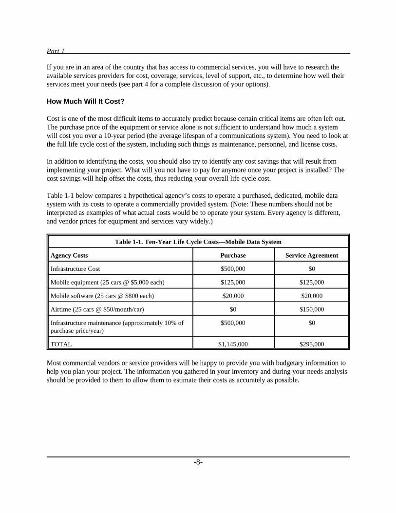
Table 1-1 below compares a hypothetical agency’s costs to operate a purchased, dedicated, mobile datasystem with its costs to operate a commercially provided system. (Note: These numbers should not beinterpreted as examples of what actual costs would be to operate your system. Every agency is different,and vendor prices for equipment and services vary widely.)
Table 1-1. Ten-Year Life Cycle Costs—Mobile Data System
Agency Costs Purchase Service Agreement
Infrastructure Cost $500,000 $0
Mobile equipment (25 cars @ $5,000 each) $125,000 $125,000
Mobile software (25 cars @ $800 each) $20,000 $20,000
Airtime (25 cars @ $50/month/car) $0 $150,000
Infrastructure maintenance (approximately 10% ofpurchase price/year)
$500,000 $0
TOTAL $1,145,000 $295,000
Most commercial vendors or service providers will be happy to provide you with budgetary information tohelp you plan your project. The information you gathered in your inventory and during your needs analysisshould be provided to them to allow them to estimate their costs as accurately as possible.
Chapter 1
-9-
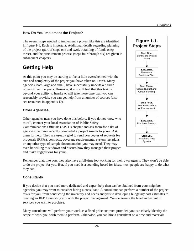
How Do You Implement the Project?
The overall steps needed to implement a project like this are identifiedin figure 1-1. Each is important. Additional details regarding planningof the project (part of steps one and two), obtaining of funds (stepthree), and the procurement process (steps four through six) are given insubsequent chapters.
Getting Help
At this point you may be starting to feel a little overwhelmed with thesize and complexity of the project you have taken on. Don’t. Manyagencies, both large and small, have successfully undertaken radioprojects over the years. However, if you still feel that this task isbeyond your ability to handle or will take more time than you canreasonably provide, you can get help from a number of sources (alsosee resources in appendix D).
Other Agencies
Other agencies near you have done this before. If you do not know whoto call, contact your local Association of Public-SafetyCommunications Officials (APCO) chapter and ask them for a list ofagencies that have recently completed a project similar to yours. Askthem for help. They are usually glad to send you copies of requests forproposals (RFPs), contracts, coverage requirements, system test plans,or any other type of sample documentation you may need. They mayeven be willing to sit down and discuss how they managed their projectand make suggestions for yours.
Remember that, like you, they also have a full-time job working for their own agency. They won’t be ableto do the project for you. But, if you need is a sounding board for ideas, most people are happy to do whatthey can.
Consultants
If you decide that you need more dedicated and expert help than can be obtained from your neighboragencies, you may want to consider hiring a consultant. A consultant can perform a number of the projecttasks for you, from conducting the inventory and needs analysis to developing budgetary cost estimates tocreating an RFP to assisting you with the project management. You determine the level and extent ofservices you wish to purchase.
Many consultants will perform your work as a fixed-price contract, provided you can clearly identify thescope of work you wish them to perform. Otherwise, you can hire a consultant on a time and materials
Step One.Identify the Project
Team
Step Two.Develop a
Business Plan
Step Three.Create Budget and
Obtain Funding
Step Four.Determine Method
of Procurement
Step Five.Purchase System
Step Six.Install and Test
System
Figure 1-1.Project Steps
Part 1
-10-
basis. In the latter case, your risk is higher, since you may not have any cap on the amount of money spentor any guarantee that your project will be finished when you run out of money to pay the consultant. Theauthors recommend, whenever possible, that you create a clear scope of work and have the consultant giveyou a firm quote. Have proposers provide you with unit costs (hourly rate) for additional work and set “notto exceed” limits.
Depending on your agency’s purchasing rules, you may need to create an RFP for consulting services. Ifyou do, follow the same general steps that are outlined in chapter 4 for competitive procurements.
Again, your nearby agencies are a great source of information about consultants. They can tell you whothey have used and tell you whether they were satisfied with the consulting firm’s services. Make sure thatwhen you are evaluating potential consultants they have completed similar projects.
Vendors
One of the most useful sources of information are the vendors of the products you are considering. Manyhave created libraries of articles (often called “white papers”) written by industry experts, which explainthe advantages and disadvantages of the various technologies. Most want to help educate you because theyknow that the better informed you are, the better buying decision you will make. Just remember that theyare trying to sell you their product, so accept their information, but do the product comparisons yourself.

Chapter 2
-11-
Chapter 2_____
Planning the Project
Realistic Schedule
One of the first things you need to develop when planning your project is an implementation schedule. Theschedule should identify all major tasks and milestones and should allow enough time for the project to bedeveloped, funded, and implemented. If you are applying for a grant, you may also need to add a periodafter implementation to comply with the grant’s evaluation requirements.
A clear time line, identifying all of the milestones you expect to reach during the various phases of theproject’s implementation, is essential. Not only will it help all of your team to understand what has to bedone and when, it will help reviewers get a much better perspective on what you are proposing.
Project Team(s)
Some projects are large enough that two project teams are needed and formed: a project steering committeeand a project implementation team.
The steering committee is usually more involved with high-level planning and policy decisions, withoutgetting actively involved in the details of the project. The steering committee often is composed of high-level representatives of the user agencies and/or departments, such as city/county managers, sheriffs, policeand fire chiefs, finance directors, and sometimes elected officials. The purpose of the steering committee isto ensure support for the project at the highest levels of the organization. You need political, financial, andadministrative support for your project to become a reality. Without that support, your project may nevereven get started, regardless of the need.
The other project team (or the only one in those cases where two teams are not needed or perhaps notpossible) is the implementation team. The implementation team is the keystone upon which your project’ssuccess depends. This team must have the ability to effectively deal with both the technical complexity of acommunications project and the organizational challenges associated with managing the project.
Part 1
-12-
Project Manager
Like any other team, the person selected to lead the implementation group is critical. The key abilitiesneeded in the project manager are organizational skills and people skills. Knowledge of the technicalaspects of the project is helpful, but not critical. The project manager ensures that the team works smoothlytogether, makes sure that all tasks are completed on time and correctly, and solves the various problemsthat arise during the project. Pick someone who knows how to get things done.
Regardless of the skill of the project manager, that person will not be effective if he or she is not given thefollowing:
Responsibility. The project manager must know that the ultimate success of the project is dependent onhim or her and also that he or she will be held accountable for the project’s success or failure.
Authority. No manager can succeed if given the responsibility but not the authority to make sure thenecessary project tasks are carried out. The project manager must be empowered by the steering committeeor other executive sponsor of the project to get and use whatever resources are needed to make the project asuccess.
Time. One of the most frequent causes for the delay or failure of a large project is not giving the projectmanager the time needed to do the job. Expecting to take someone who is currently doing one full-time joband assigning the project management tasks to him or her as well is just poor management. Estimate thetime needed to effectively manage the project and then adjust the project manager’s workload accordingly.Be sure to include time for unseen delays and for fine-tuning once the project is operational.
Management support. If a project manager’s manager does not support the project, it is unlikely that theproject manager will be successful. Make sure that the person selected has the backing of his or hermanagement team.
Physical resources. It may seem obvious, but an adequate space within which to work is an absolutenecessity. The project manager will spend hours on the telephone, in meetings, and reviewing detailedtechnical documents. Adequate space, privacy, and quiet are mandatory. Administrative support for taskssuch as copying, filing, typing, and scheduling make the project manager more productive.
Other Team Members
Implementation team members should be selected to provide the project with the best chance for success.Each member should bring a unique perspective to the group. One could be technical. Others might befinancial (including finance, budget, and purchasing) and legal. Still more might represent different aspectsof the user community. (And don’t forget to include your vendor on your team, once a vendor has beenselected. Including the vendor on your team will minimize the chance of any last minute, unhappysurprises.)
Whatever their qualifications, team members should be willing to take on the assignment of certain tasksfrom the implementation schedule and have the time to accomplish those tasks. Like the project manager,
Chapter 2
-13-
team members must be willing to embrace the responsibility of performing their assignments and beallowed the time by the employing organizations to do those assignments well.
Budget
For funding administrators to evaluate your request for funds, you must be able to explain your budget indetail, particularly if you are applying for Federal funds. The budget must be reasonable for the tasks andequipment proposed, and the relationship of the budget to the project plan must be clearly identified andcommunicated.
Budgets should include all costs associated with the project. This could include costs for personnel, fringebenefits, computer hardware and software, other end-user equipment, telecommunications services andrelated equipment, furniture and space, supplies, and maintenance. If a new facility is needed to housepersonnel and/or equipment, construction costs may also be included.
If you are applying for a State or Federal grant, make sure you obtain a copy of the grant applicationguidelines (see resources in appendix D). Most grants require detailed budget information and mandate thatit follow a specific format. Failure to follow the rules often results in immediate disqualification of thegrant application.
Chapter 3
-15-
Chapter 3_____
Obtaining Funds
For many agencies, obtaining funds is the most difficult part of a communications project. Projects like thisare expensive, and, as a result, funding may take months or even years to accomplish. Begin your effortsfor obtaining funds far in advance of when you need the new system to be operational.
More detailed information about public safety funding can be found in the Report on Funding Mechanismsfor Public Safety Radio Communications, published by the Public Safety Wireless Network (PSWN)Program (see resources in appendix D).
Types of Funds
For most local agencies, the types of funds available fall into two general categories: local revenue fundsand grants. Local revenue funds are obtained by local governments through local taxes (e.g., sales tax,property tax), user fees, and other user charges, plus through the issuing of debt instruments, like bonds.Grants are funds made available to local agencies from State and Federal government agencies, as well asfrom private sources (like foundations). Grants usually require you to submit a formal application to justifyyour request for funding.
Sources of Funds
The process you must go through to obtain funding for your project will vary depending on who owns thefunds you want. This section focuses primarily on government sources of funds, not private sources.
Remember, to fully fund your project, you may need to get money from several different entities. In fact,many of the Federal grants require a certain amount of matching funding. Learning as much as possibleabout all the possible sources is in your best interest.
Federal Sources
Local governments receive public safety funding from Federal sources primarily through grants andcooperative agreements. A third source of funds for law enforcement has been asset forfeiture funds. (Mostof the Federal public safety funding in the last decade has been primarily for law enforcement, with littlespecifically earmarked for fire and emergency medical services.) Grants fall into two categories: block (orformula) grants and discretionary (or categorical) grants.
Part 1
-16-
Most public safety funding has come through the U.S. Department of Justice (DOJ). However, funds forinfrastructure projects like communications are also possibly available through the U.S. Department ofCommerce [National Telecommunications and Information Administration (NTIA)], the U.S. Departmentof Transportation (DOT), and the Federal Emergency Management Agency (FEMA).
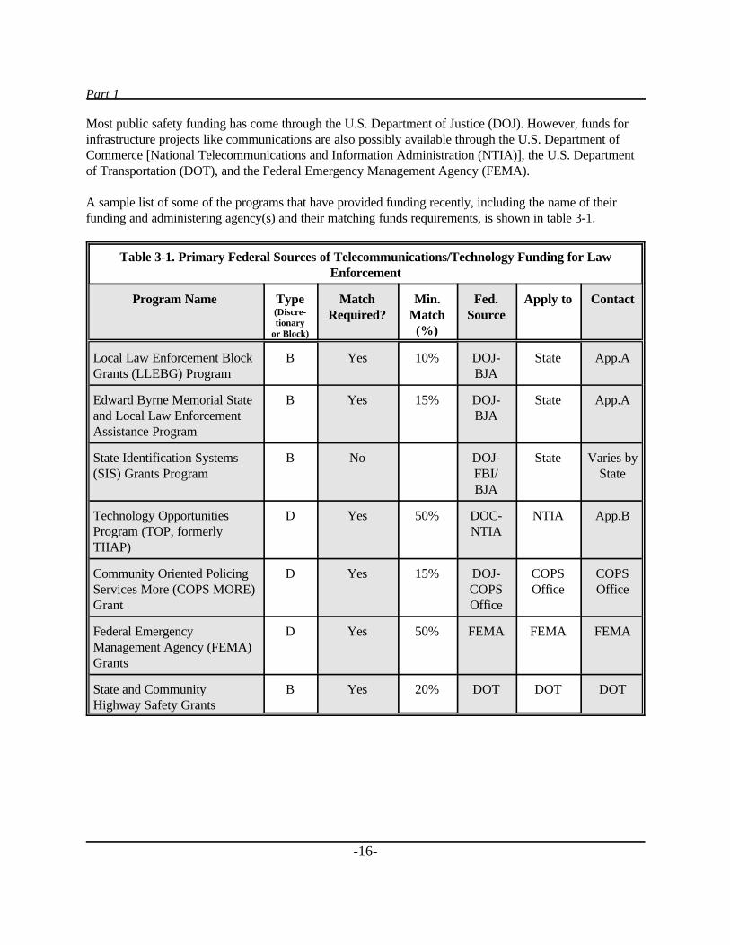
A sample list of some of the programs that have provided funding recently, including the name of theirfunding and administering agency(s) and their matching funds requirements, is shown in table 3-1.
Table 3-1. Primary Federal Sources of Telecommunications/Technology Funding for LawEnforcement
Program Name Type(Discre-tionary
or Block)
MatchRequired?
Min.Match(%)
Fed.Source
Apply to Contact
Local Law Enforcement BlockGrants (LLEBG) Program
B Yes 10% DOJ-BJA
State App.A
Edward Byrne Memorial Stateand Local Law EnforcementAssistance Program
B Yes 15% DOJ-BJA
State App.A
State Identification Systems(SIS) Grants Program
B No DOJ-FBI/BJA
State Varies byState
Technology OpportunitiesProgram (TOP, formerlyTIIAP)
D Yes 50% DOC-NTIA
NTIA App.B
Community Oriented PolicingServices More (COPS MORE)Grant
D Yes 15% DOJ-COPSOffice
COPSOffice
COPSOffice
Federal EmergencyManagement Agency (FEMA)Grants
D Yes 50% FEMA FEMA FEMA
State and CommunityHighway Safety Grants
B Yes 20% DOT DOT DOT
Chapter 3
-17-
Block grants. Block grants are distributed by the Federal Government to States based on a statutoryformula (which may take into account factors like population or crime rate). States then distribute theirshare of the block grant funds to local and State government agencies. The Federal Government issuesbroad guidelines about what type of things the funds can be used for, but the States process the actualapplications.
The largest single formula grant source for law enforcement is the Edward Byrne Memorial State andLocal Law Enforcement Assistance Program. Each State has an established office for assisting in theapplication for law enforcement-related block grants (at minimum to service the Byrne Program). The grantoffices have various names within each State, although State planning agency is the most common. A list ofthe agency names and contact numbers for Byrne Program assistance in each State is given in appendix A.
In addition to administering the Byrne funds, these State agencies are often valuable resources for help inwriting grants and for information about other funding sources.
A second block grant program, the Local Law Enforcement Block Grants (LLEBG) program, also hasrecently been a source of funds. If a jurisdiction is eligible for funding and completes an application, theBureau of Justice Assistance (BJA) will make an award. The LLEBG program is not a competitiveprogram.
Discretionary grants. Discretionary grants are usually focused on a specific purpose and are administereddirectly by agencies within the Federal Government. The rules for qualification, deadlines for applicationsubmittal, funds available, and format will be different for each type of grant and each agencyadministering the funds. Most require the local agency to provide some percentage of matching funds (seetable 3-1).
The primary Federal funding agency for law enforcement grants is the Office of Justice Programs (OJP),within DOJ. The offices within OJP that make grants include BJA, Bureau of Justice Statistics (BJS),Corrections Program Office, Drug Courts Program Office, National Institute of Justice (NIJ), Office ofJuvenile Justice and Delinquency Prevention (OJJDP), Office for Victims of Crime, and the ViolenceAgainst Women Office.
In recent years, a major source of law enforcement funding has been the Office of Community OrientedPolicing Services (COPS), also within DOJ.
It is extremely important to follow all of the rules dictated by the funding agency regarding the applicationprocess. Each agency receives hundreds of applications for funding and will only consider applications thatprovide all of the necessary information and in the required format. Even if you have a great project idea, itwill not get considered if you neglect to comply with the agency’s application instructions.
Federal asset forfeiture funds. Asset forfeiture programs are administered by two different Federalagencies: DOJ and the Department of the Treasury. Funds for these programs are obtained from forfeituresassociated with the breaking of Federal law. Federal agencies have the authority to share fund revenueswith any State and local law enforcement agencies that assisted in successful forfeiture cases.
Part 1
-18-
If your agency has been involved in assisting a Federal agency and that case resulted in the seizing ofassets, you should contact the Executive Office of Asset Forfeiture within either DOJ or Treasury forinformation about sharing of funds or property.
State Sources
The availability of State money to fund local public safety projects varies significantly from State to State(with the exception of the State-administered Federal block grants). Some States administer their own grantprograms through a variety of different departments (e.g., Public Safety, Health, Human Services,Emergency Management, General Services, Business and Economic Development). The State planningagency administering the Byrne Program funds is the best place to start when inquiring into State sourcesof grant funding.
Sources other than traditional public safety-related State agencies are also worth exploring. For example, inColorado, some police agencies have received Energy Impact Grants through the Division of Local Affairs.These are mitigation funds collected from oil and gas producers that are then returned to counties wherepetroleum extraction occurs. In this case, the funds are not public safety specific, but rather countyspecific.
Depending on the State, 911 and E911 surcharges are administered by the State and/or by the localgovernment and may be available for communications projects. If you are unfamiliar with how 911surcharges are administered in your State, contact either the national office or your State chapter of theNational Emergency Number Association (NENA) (see resources in appendix D). NENA should be able totell you who administers the funds for your agency and provide you with a contact name and number.
A number of States are planning or implementing statewide wireless communications projects. In someinstances, these projects include providing access for local public safety agencies in addition to Stateagencies. Each State has funded these large-scale projects in various ways, ranging from State tax revenuesto bonds to user fees. Unfortunately, each State administers these projects differently and through differentdepartments. To find out if a project like this is under way in your State, try contacting the department ordivision responsible for telecommunications or the State law enforcement agency.
Local Sources
Local governments spend the revenues they collect in several ways. The largest percentage is through thegeneral fund, which pays for the overall operational budget for the government. Funding requests made to ageneral fund must usually follow the budget preparation rules of the local government and will becompeting against all other departments within that government entity.
In addition, the local government may have decided to incur long-term debt by issuing bonds, certificates ofparticipation, or similar instruments. The money raised in this manner is used to pay for many multiple-year or high-cost projects. In some cases, a specific tax may be levied (kept separate from the general fund)that is earmarked to pay for certain capital improvement projects. (Remember, in some States, permissionto issue debt or special taxes may require a vote of the citizens, which requires a ballot initiative and asignificant amount of time and effort, with no guarantee of passage.)
Chapter 3
-19-
Single agency versus multiple agencies. Over the past decade, increasingly agencies have been joiningtogether to fund cooperative communications projects. The benefits of increased interoperability andreduced individual agency cost have overcome traditional resistance to sharing. Agencies have createdintergovernmental agreements (IGAs), joint powers authorities (JPAs), nonprofit corporations, and othercreative mechanisms for allowing the various agencies to contribute funds to a joint project.
Most agencies come up with some formula to determine the share of money that each must contribute.Formulas may be based on population, coverage area, number of transactions, number of units/officers, orany combination of these and other factors.
In addition to providing a mechanism for funneling local funds, a multiagency consortium often is able toobtain grant funds that a single agency might not. Many Federal grant programs look favorably oncooperative sharing of resources.
If you are considering creating a multiagency funding authority, contact several agencies that haveparticipated in projects like this for suggestions on how to structure and fund your organization. They cangive you valuable information on the time it takes to get all the various local governments to come toagreement, what has worked well for them, and what they would suggest you do differently.
“Selling” Your Need
Regardless of who you ask for funds, you must convince them that your project is necessary and that youwill provide the most beneficial use of their dollars. The competition for funds is intense, and everyonebelieves that his or her needs are real. Getting the funds often depends more on your ability to present yourneeds in a businesslike and professional manner than on the need itself.
For example, the Technology Opportunities Program (TOP) of the Department of Commerce publishesextensive guidelines for preparing applications on its World Wide Web site (see resources in appendix D).In addition to a detailed budget, a TOP applicant must be able to clearly answer the following questions:
$ What are the goals of the project?$ What are the anticipated outcomes?$ How will the proposed solution make a difference in the community?$ How many sites are there and where are they located?$ Which communities are to be served?$ What organizations are participating as project partners?$ What technologies are to be employed?$ What will users do with the technology?
The review team needs to know that the project you propose is worth doing and that your team can actuallydo it. The feasibility of the project will be judged based on your technical approach, the skills of your teammembers, and your budget estimates, schedule, and time line, as well as the long-term operational costs ofthe project. Failure to clearly define any of these items could be cause for rejection of your request.
Part 1
-20-
Involve as many people as possible in reviewing your project request before you submit it to the fundingagency. Have someone who is not directly involved in your project read it for clarity and purpose. Haveyour financial staff person review the budget for completeness and accuracy. Have a technical editorproofread it for punctuation and grammar. Have another agency that has been successful applying forfunds make suggestions for improvement. Above all, make sure the proposal tells a complete and cohesivestory and that no questions are left unanswered.
Remember, if you miss your chance with this proposal, you may have to wait a year to submit another. Inthe case of Federal grants, if the appropriations for that program are cut off next year, you may never getanother chance.
Getting Help
This section identifies some of the Federal resources that you may find useful when looking for funding.Many more resources exist than are listed below. Appendix D lists a number of additional Web sites thatmay also be helpful.
For information about Federal grant programs in general:
$ Get a copy of the Catalog of Federal Domestic Assistance through your local library forinformation on all Federal grant opportunities. The Catalog also can be ordered (for a fee) bycalling 202–512–1800.
$ Search the computerized database of grant programs, called FAPRS, maintained by the GeneralServices Administration.
For information about DOJ programs specifically:
$ Contact the DOJ Response Center at 800–421–6770.
$ Contact the National Criminal Justice Reference Service (NCJRS) through its Web site athttp://www.ncjrs.org or via e-mail at [email protected].
$ Contact the BJA Clearinghouse at 800–688–4252. (NCJRS, cited above, is the online version ofthe Clearinghouse.)
For information about DOJ block grant programs administered by each State:
$ Contact the applicable State planning agency given in appendix A.
For information about TOP grant programs:
$ Contact the applicable NTIA State Single Point of Contact (SPOC) given in appendix B.
Chapter 3
-21-
To automatically receive notice about all solicitations sent out by DOJ:
$ Ask NJCRS (see above for contact information) to put you on its mailing list for grant proposalsolicitations.
$ Check the postings on the BJA home page at http://www.ojp.usdoj.gov/BJA.
For help writing a grant:
$ For law enforcement officials, the FBI’s National Academy Program offers a noncredit course ongrant program development and budgetary issues. Contact the FBI for more information.
$ Contact other agencies that have successfully applied for the grant you are interested in. Ask themfor copies of their grant proposals. Lists of successful applicants are found on many of the FederalWeb sites, in particular at http://www.ncjrs.org
Additional information sources are identified in the resources in appendix D.

Chapter 4
-23-
Chapter 4_____
Buying What You Need
Once funding has been secured, the purchasing process can begin. This section discusses the primary waysthat communications systems have been purchased but does not attempt to itemize every variation that hasbeen used.
How to Buy
Most government agencies have specific purchasing rules and regulations that must be followed forpurchases to be legal. You should consult with the staff from your purchasing division or department todetermine the rules that govern your agency.
Competitive Procurement
A competitive procurement usually involves the development of purchasing specifications by the localagency and then issuing of a Request for Quotation (RFQ) and/or a Request for Proposal (RFP). Multiplevendors respond to the RFQ with a bid (or to the RFP with a proposal) to provide what the agency hasrequested. A competitive procurement is designed to encourage competition among vendors to encouragefair pricing.
An RFQ is generally used to purchase commodities, which can be easily described and for which there areseveral suppliers. Most awards that result from RFQs are based on low bid.
An RFP is used for purchasing more complex items, like communications systems, for which a number ofvariables besides price may influence an award decision. For example, other variables could includemaintenance hours, financial stability of the company, references from other clients, and ease of use.
Because it is the most common method for purchasing a communications system, the competitiveprocurement process using an RFP is detailed in a section below.
Noncompetitive Procurement
Local governments can contract for services in many cases without going out to bid. Check with yourcity/county purchasing department to see if there are any clauses in your policies and procedures thatwould work to your benefit. Two common examples that are used with communications are sole sourceprocurement and contract for operational services.

Part 1
-24-
Sole source procurement. In a sole source procurement, goods and/or services can be purchased from avendor that has previously been awarded a contract, usually through a competitive bid process. Thereasoning is that if that vendor is the “sole source” for additional items that are compatible with itemsalready supplied, then another competitive procurement does not need to be conducted. For example, if youhad purchased computer software from a vendor and now decide that you want to upgrade to a newerversion of its software, and since it is the only one that makes that software, you could issue that vendor apurchase order without going to bid.
Each jurisdiction deals with the issue of sole source procurement differently. Some allow sole sourcing tovendors without a previous competitive procurement. Others do not allow it at all. If there is something youwant to consider purchasing by sole source, you should check with your local purchasing manager beforeyou issue any purchase orders to make sure you are in compliance with local ordinances.
Contract for operational services. Agencies contract for many types of operational services, like cellulartelephone service and pager service. Many purchasing divisions treat service contracts differently than theytreat contracts for purchase. You may only need to show that you have sufficient funds in your budget topay for the service you want. In some cases, you may not even have to prove that since the belief is thatyou will cancel the service if you have no more money in your budget.
Some agencies have purchased mobile data cellular service [e.g., Cellular Digital Packet Data (CDPD)service] through noncompetitive service agreements and, thus, have completely avoided the competitiveprocurement of radio infrastructure equipment.
As always, you should confirm with purchasing that there are no restrictions to your contracting forservices.
Cooperative Purchasing
Cooperative purchasing refers to the practice of buying from another agency’s competitive procurement.The most common type is the ability of a local agency to buy from the State’s price agreement list. Stategovernments routinely solicit bids for thousands of commonly used items, like computers and printers, atfixed prices. Vendors promise to supply all of the items the State wants at that fixed price for a fixedperiod, frequently 1 year. Local governments can buy from these awards throughout the year at volumediscount prices, usually without going through their own bidding process.
Check with your agency’s purchasing manager to determine whether your State allows you to purchaseitems from its awards. Or contact the State purchasing division directly to see if it supports this type ofcooperative purchasing.
Chapter 4
-25-
Leasing
Leasing is not really a type of procurement, but rather is a way to pay once a procurement has been made.One of the above procurement methods would be used to select a vendor and determine a price. Once thatwas done, the local government could decide to finance the purchase and pay for it over a period of monthsor years, rather than purchase the equipment outright.
Leasing can be advantageous in those cases where you do not receive all of your funding at one time. Forexample, if sales tax revenues are funding your project, the revenues are spread out over a number of years.In that case, it might make sense to also spread your payments out over a similar number of years. Thetotal cost of the purchase will be higher (because of interest charges), but you will get use of the systemsooner than if you wait until all of the revenues are received.
With most government leases, the government owns the equipment upon contract completion. Theequipment can then be traded or upgraded as technology improves or requirements change.
Leasing companies are generally willing to work with your agency to structure the lease to conform to yourbudget, tax, cash flow, delivery, or regulatory restraints. Because of the number of companies now offeringleasing to government agencies, your purchasing agent may decide to ask a number of companies to bid onproviding the lease, thus ensuring that you receive the most favorable finance rate.
Outsourcing
Outsourcing is one of the newer methods of procurement, at least at the local government level.Outsourcing refers to hiring an outside company to perform services traditionally performed by agencystaff. The level of service can vary, from just providing the people to operate agency equipment tocontracting for provision of people and equipment.
For example, an agency in Pennsylvania outsourced its entire emergency communications center. Thevendor supplied the facility where the communications center was located, the people to manage and staffthe center, the computer-aided dispatch system, the telephone equipment, and all other aspects of the center.The agency estimated that it would actually save money over the 10-year course of the contract by notoperating the center itself.
Because relatively few governments have done this, you may want to talk to companies in your area thathave outsourced services. While somewhat new to local government, it has been used for a number of yearsin corporate settings, with significant cost savings.
Request for Information (RFI)
Technically, this is not a procurement. However, it can allow you to gather information in a structuredmanner that will allow you to determine what products and services are currently on the market and theirassociated costs. Generally, the vendors provide only estimates of costs, but these are extremely useful increating your budget.
Part 1
-26-
An RFI usually describes the scope of the project, your projected time line, and any other descriptiveinformation about the project. Vendors are asked to provide information about their suggested solution,with supporting product material and cost estimate information.
In some cases, vendors have been required to respond to an RFI to be eligible to move to the next step andreceive the RFP.
Competitive Procurement (RFP)
The goal of this section is to provide additional details about competitive procurements using an RFP. It isnot intended to cover every aspect of the procurement process, but rather is intended to give you anoverview of what is involved. Specific requirements for the RFP should be requested from your localpurchasing manager.
Request for Proposal (RFP)
As mentioned previously, an RFP is used for purchasing more complex items for which a number ofvariables besides price are important to the purchasing decision (see figure 4-1).
RFP Process
The following steps are involved in the RFP process (and are summarized in figure 4-1).
Develop the RFP. There are three main sections of an RFP: the instructions to proposers, the terms andconditions of purchase, and the technical specifications. Templates for the first two are generally providedto you by your purchasing agent. You may then need to add, delete, or modify portions of these asappropriate to the needs of your project.
The development of the technical specifications is usually the responsibility of the project team. Thespecification must be clear and comprehensive so that both you and the vendor know precisely what iswanted and what is expected of each party. Avoid over specifying, as it can limit the number of vendorsthat respond and, thus, limit your options.
You need to make sure that your RFP, at minimum, does each of the following:
$ Describes the problem being addressed.
$ Describes the existing environment (e.g., existing equipment, operational procedures, agencystandards, constraints).
$ Describes the required project outcomes.
$ Describes the scope and standard of service required in ALL areas (i.e., user functionality, systemresponse times, delivery schedule, service levels, training).
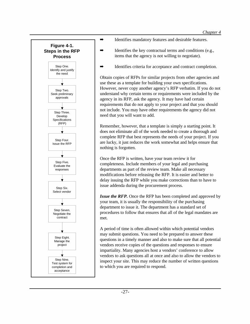
Chapter 4
-27-
$ Identifies mandatory features and desirable features.
$ Identifies the key contractual terms and conditions (e.g.,items that the agency is not willing to negotiate).
$ Identifies criteria for acceptance and contract completion.
Obtain copies of RFPs for similar projects from other agencies anduse these as a template for building your own specifications.However, never copy another agency’s RFP verbatim. If you do notunderstand why certain terms or requirements were included by theagency in its RFP, ask the agency. It may have had certainrequirements that do not apply to your project and that you shouldnot include. You may have other requirements the agency did notneed that you will want to add.
Remember, however, that a template is simply a starting point. Itdoes not eliminate all of the work needed to create a thorough andcomplete RFP that best represents the needs of your project. If youare lucky, it just reduces the work somewhat and helps ensure thatnothing is forgotten.
Once the RFP is written, have your team review it forcompleteness. Include members of your legal and purchasingdepartments as part of the review team. Make all necessarymodifications before releasing the RFP. It is easier and better todelay issuing the RFP while you make corrections than to have toissue addenda during the procurement process.
Issue the RFP. Once the RFP has been completed and approved byyour team, it is usually the responsibility of the purchasingdepartment to issue it. The department has a standard set ofprocedures to follow that ensures that all of the legal mandates aremet.
A period of time is often allowed within which potential vendorsmay submit questions. You need to be prepared to answer thesequestions in a timely manner and also to make sure that all potentialvendors receive copies of the questions and responses to ensureimpartiality. Many agencies host a vendors’ conference to allowvendors to ask questions all at once and also to allow the vendors toinspect your site. This may reduce the number of written questionsto which you are required to respond.
Step One.Identify and justify
the need
Step Two.Seek preliminary
approvals
Step Three.Develop
Specifications(RFP)
Step Four.Issue the RFP
Step Five.Evaluate theresponses
Step Six.Select vendor
Step Seven.Negotiate the
contract
Step Eight.Manage the
project
Step Nine.Test system forcompletion and
acceptance
Figure 4-1.Steps in the RFP
Process
Part 1
-28-
Allow vendors enough time to prepare a thorough response to your RFP. Depending on the complexity ofthe project, a period of from 1 to 2 months is common.
Proposals must be submitted by the date and time indicated in the RFP. Be sure to request enough copiesfor all evaluation team members. If a vendor submits a proposal after that time, its proposal should not beopened or included in the evaluation process.
Once the proposals are received and verified by purchasing, distribute copies to your evaluation team,which will include your implementation team as well as others with a vested interest in the project.
Evaluate responses. When evaluating the responses to the RFP, you must consider a number of items:
$$ Compliance. Does the proposal comply with the required specifications in the RFP? If it does not,eliminate the proposal from further consideration.
$$ Value. Value is more than just price. It may include all or some of the following: purchase price,quality, warranties, maintenance costs, training, service, response time, reliability, companystability, delivery time, and contract terms and conditions, among others.
$$ Total Life Cycle Costs. How much will the system cost over its expected life. In other words, ifyou expect the system to last 10 years, the life cycle cost would include the initial purchase pricePLUS all operating and maintenance costs incurred over the entire 10 years. A system that has alow initial purchase price may have high maintenance costs that, over time, may cause its total lifecycle cost to exceed that of a vendor with a higher initial purchase price.
$$ Company References. Talk to recent clients who have made similar purchases from the vendorsfor feedback on performance. Talking to several people from each client site will give you a morerounded impression of each vendor’s performance.
Evaluate the proposals against evaluation criteria that were defined before the proposals were received. Thegoal is to select the proposal that best meets the defined needs and to determine whether the vendor has theability to perform the work.
Read each proposal thoroughly. Use a standard evaluation format (e.g., a spreadsheet or written form) tohelp you compare responses of vendors more easily. Keep copies of the results.
Have your agency’s purchasing and/or legal staff review the terms and conditions of the proposal to ensurethat the vendor has not counter proposed any terms that would be unacceptable to your agency.
The entire evaluation process should be clear, fair, and equitable. Treating all vendors the same andkeeping good records of the results of the evaluations will help ensure that there is no basis for a protest ofyour selection.
Select vendor. If a single best vendor emerges from the above evaluation process, you can move on to thecontract negotiation phase of the process. However, it is more likely that there will be two or three vendors
Chapter 4
-29-
who appear comparable on paper (the “short list”). Before a clear winner can be selected, additional in-person demonstrations and/or interviews may be required with each of the short-listed vendors.
As a result of the demonstrations and/or interviews, each vendor may be asked to submit a best and finaloffer that allows an “apples to apples” comparison of the proposals and their value.
At this time, you should evaluate each company’s financial stability as well, through bank references, creditreports, public financial records (if a public company), and other similar checks. Get help from experiencedfinancial experts, either inside your agency or outside it, to ensure that you obtain the right information andthat it is correctly interpreted.
Another important consideration is the company’s ability to perform the work. In other words, does it haveenough staff to do your project as well as the other projects to which it is already committed. Check to seehow many concurrent projects the company is working on. Also check to see if it has adequate customersupport staff to assist you with maintenance problems after the project has been installed.
Ultimately, the final selection should represent the best value for the money, from a financially stable,responsive, and well-respected company.
The unsuccessful vendors should be notified in writing once a selection has been made. However, thefinalists should not be released from their obligation to perform until a final contract has been signedbetween the selected vendor and your agency. In the event that you are unable to successfully negotiate acontract with your selected vendor, you may wish to initiate negotiations with another of the finalists.
Negotiate contract. A written contract is mandatory. Both parties will benefit by having a document thatclearly identifies each other’s obligations.
The contract negotiation should begin as soon as possible after selection of the final vendor. Thenegotiations should be conducted between individuals from each of the parties who have the authority tomake commitments on behalf of their agency or company. Otherwise, a great deal of time and effort can beexpended during the negotiation process only to find out that the “powers that be” will not approve theresulting contract.
Your negotiators should have skills and experience in negotiating complex, high-technology contracts. Ifyou do not have such expertise within your agency, seek help from recognized experts within otherdepartments/agencies.
A copy of your agency’s Standard Contract Terms and Conditions should have been included in the RFPand should serve as the basis for negotiating a final contract. (It is usually not in the best interests of theagency to use the vendor’s standard contract terms and conditions; however, there may be circumstanceswhen this is the best option available.)
In addition to legal terms and conditions, every contract should include a project schedule. This scheduleshould set clear, identifiable milestones for completion of each phase of the project. A milestone should beeasy to measure and/or to determine that it has been completed.

Part 1
-30-
The contract should also include a specific payment schedule, which clearly identifies when and under whatcircumstances payments will be made. As much as possible, payments should be tied to project milestones,with fixed-price amounts itemized. A certain percentage of the total contract price should be retained untilthe entire project is completed to ensure that all work has been completed to your agency’s satisfaction.
The contract should specify how requests for changes in scope of work will be handled and who isauthorized to request such changes. The contract should require that all changes to the scope of a contractbe in writing (verbal authorization is not sufficient) to be binding. In addition, it is important to specify howany changes in the project cost, which may be associated with scope changes, will be handled.
Your agency’s purchasing adviser and legal advisor should always be involved in reviewing any contractdocuments before they are finalized. Otherwise, the modifications made during the negotiation process maynot be in compliance with existing governmental laws, rules, and regulations.
Ensure that the final contract is signed by the individuals from each party who are legally authorized to doso. Otherwise, the contract may be ruled invalid.
Manage the project. Managing the installation is one of the most important aspects of a successful project.Once the contract is signed, it is critical to monitor vendor performance, the contract terms, and thepayments.
The project manager must ensure that the agency is getting what it asked for and that required milestonesare met. Payments should only be made if milestones are completed as promised. However, paymentsshould not be unreasonably withheld either. Ensure that payments are made on time for work properlyperformed.
One key to successful project management is open and frequent communications between the agency’sproject manager and the vendor’s project manager. Raise questions or concerns as soon as they arise; don’twait for the next scheduled meeting. Waiting could cause a delay in your implementation.
Project management is a subject upon which numerous books have been written and for which manyclasses are taught. It is beyond the scope of this guidebook to cover all aspects of good projectmanagement. A number of excellent project management software programs are available for helping withthe planning, scheduling, and recording of the project tasks. Many include guidebooks on projectmanagement with the software.
Acceptance testing. The specifications should have indicated the system parameters to be tested andaccepted. A thorough test plan should be submitted by the vendor. Tests should be run and witnessed by theagency before the system is turned over to the agency. All deficiencies should be corrected before finalacceptance and final payment.
-31-
PART 2
WIRELESS COMMUNICATIONS
TECHNOLOGY
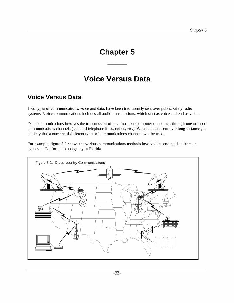
Chapter 5
-33-
Chapter 5_____
Voice Versus Data
Voice Versus Data
Two types of communications, voice and data, have been traditionally sent over public safety radiosystems. Voice communications includes all audio transmissions, which start as voice and end as voice.
Data communications involves the transmission of data from one computer to another, through one or morecommunications channels (standard telephone lines, radios, etc.). When data are sent over long distances, itis likely that a number of different types of communications channels will be used.
For example, figure 5-1 shows the various communications methods involved in sending data from anagency in California to an agency in Florida.
Figure 5-1. Cross-country Communications
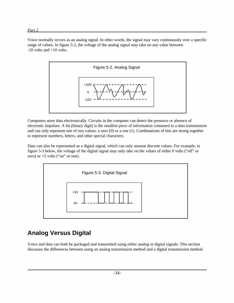
Part 2
-34-
Voice normally occurs as an analog signal. In other words, the signal may vary continuously over a specificrange of values. In figure 5-2, the voltage of the analog signal may take on any value between-10 volts and +10 volts.
Computers store data electronically. Circuits in the computer can detect the presence or absence ofelectronic impulses. A bit (binary digit) is the smallest piece of information contained in a data transmissionand can only represent one of two values: a zero (0) or a one (1). Combinations of bits are strung togetherto represent numbers, letters, and other special characters.
Data can also be represented as a digital signal, which can only assume discrete values. For example, infigure 5-3 below, the voltage of the digital signal may only take on the values of either 0 volts (“off” orzero) or +5 volts (“on” or one).
Analog Versus Digital
Voice and data can both be packaged and transmitted using either analog or digital signals. This sectiondiscusses the differences between using an analog transmission method and a digital transmission method.
Figure 5-3. Digital Signal
+5V
0V
Figure 5-2. Analog Signal
+10V
0
-10V
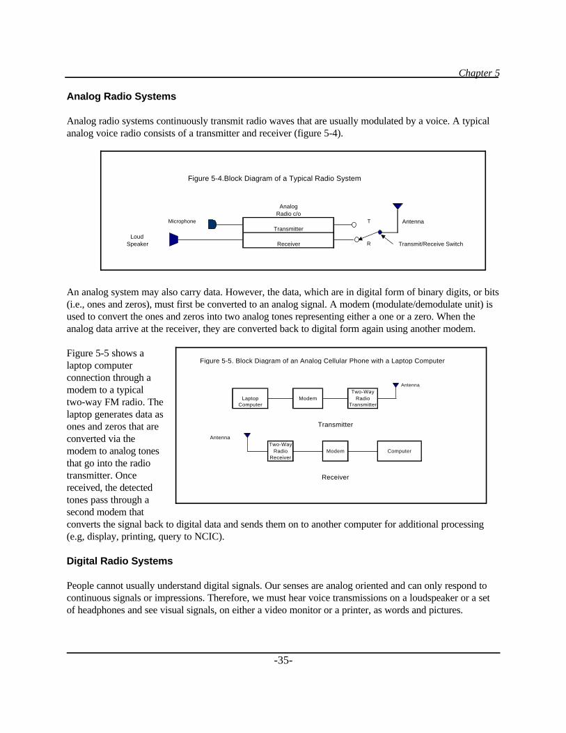
Chapter 5
-35-
Analog Radio Systems
Analog radio systems continuously transmit radio waves that are usually modulated by a voice. A typicalanalog voice radio consists of a transmitter and receiver (figure 5-4).
An analog system may also carry data. However, the data, which are in digital form of binary digits, or bits(i.e., ones and zeros), must first be converted to an analog signal. A modem (modulate/demodulate unit) isused to convert the ones and zeros into two analog tones representing either a one or a zero. When theanalog data arrive at the receiver, they are converted back to digital form again using another modem.
Figure 5-5 shows alaptop computerconnection through amodem to a typicaltwo-way FM radio. Thelaptop generates data asones and zeros that areconverted via themodem to analog tonesthat go into the radiotransmitter. Oncereceived, the detectedtones pass through asecond modem thatconverts the signal back to digital data and sends them on to another computer for additional processing(e.g, display, printing, query to NCIC).
Digital Radio Systems
People cannot usually understand digital signals. Our senses are analog oriented and can only respond tocontinuous signals or impressions. Therefore, we must hear voice transmissions on a loudspeaker or a setof headphones and see visual signals, on either a video monitor or a printer, as words and pictures.
AnalogRadio c/o
Microphone T AntennaTransmitter
Loud Speaker Receiver R Transmit/Receive Switch
Figure 5-4.Block Diagram of a Typical Radio System
Antenna
Two-WayLaptop Modem Radio
Computer Transmitter
Transmitter
AntennaTwo-Way
Radio Modem ComputerReceiver
Receiver
Figure 5-5. Block Diagram of an Analog Cellular Phone with a Laptop Computer
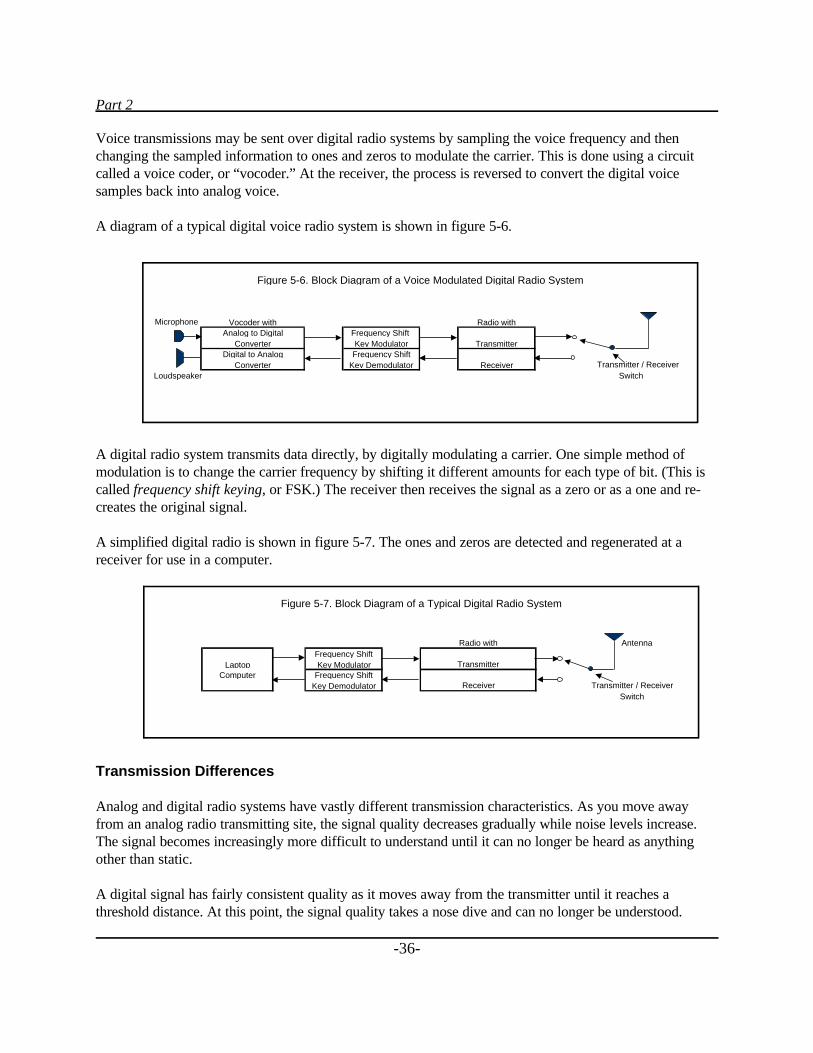
Part 2
-36-
Voice transmissions may be sent over digital radio systems by sampling the voice frequency and thenchanging the sampled information to ones and zeros to modulate the carrier. This is done using a circuitcalled a voice coder, or “vocoder.” At the receiver, the process is reversed to convert the digital voicesamples back into analog voice.
A diagram of a typical digital voice radio system is shown in figure 5-6.
A digital radio system transmits data directly, by digitally modulating a carrier. One simple method ofmodulation is to change the carrier frequency by shifting it different amounts for each type of bit. (This iscalled frequency shift keying, or FSK.) The receiver then receives the signal as a zero or as a one and re-creates the original signal.
A simplified digital radio is shown in figure 5-7. The ones and zeros are detected and regenerated at areceiver for use in a computer.
Transmission Differences
Analog and digital radio systems have vastly different transmission characteristics. As you move awayfrom an analog radio transmitting site, the signal quality decreases gradually while noise levels increase.The signal becomes increasingly more difficult to understand until it can no longer be heard as anythingother than static.
A digital signal has fairly consistent quality as it moves away from the transmitter until it reaches athreshold distance. At this point, the signal quality takes a nose dive and can no longer be understood.
Microphone
Transmitter / Receiver Loudspeaker
Analog to DigitalConverter
Digital to Analog
Switch
Figure 5-6. Block Diagram of a Voice Modulated Digital Radio System
Converter
Vocoder withFrequency Shift
Frequency ShiftKey Modulator
Key Demodulator
Radio with
Transmitter
Receiver
Radio with Antenna
Transmitter
Receiver Transmitter / Receiver
LaptopComputer
Figure 5-7. Block Diagram of a Typical Digital Radio System
Frequency ShiftKey Modulator
Frequency ShiftKey Demodulator
Switch
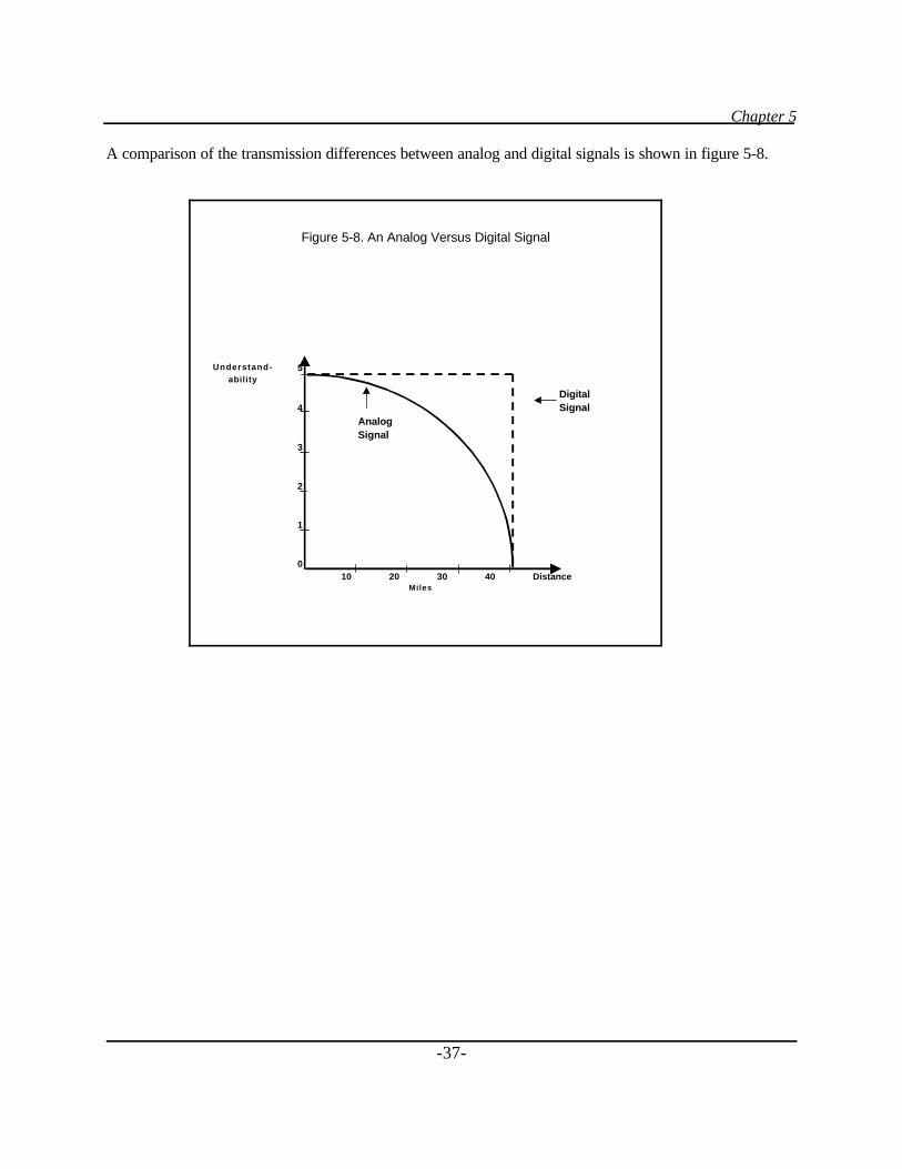
Chapter 5
-37-
A comparison of the transmission differences between analog and digital signals is shown in figure 5-8.
Understand- 5ability
Digital4 Signal
AnalogSignal
3
2
1
0 10 20 30 40 Distance
Miles
Figure 5-8. An Analog Versus Digital Signal
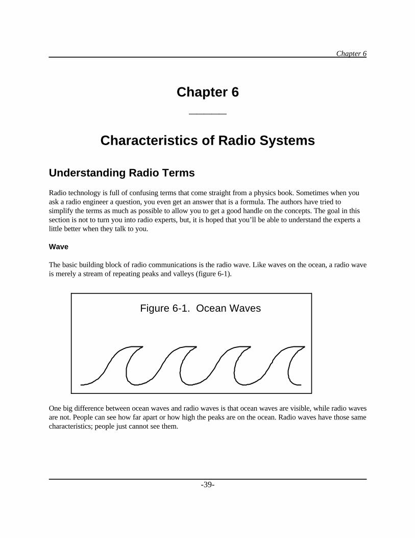
Chapter 6
-39-
Chapter 6_____
Characteristics of Radio Systems
Understanding Radio Terms
Radio technology is full of confusing terms that come straight from a physics book. Sometimes when youask a radio engineer a question, you even get an answer that is a formula. The authors have tried tosimplify the terms as much as possible to allow you to get a good handle on the concepts. The goal in thissection is not to turn you into radio experts, but, it is hoped that you’ll be able to understand the experts alittle better when they talk to you.
Wave
The basic building block of radio communications is the radio wave. Like waves on the ocean, a radio waveis merely a stream of repeating peaks and valleys (figure 6-1).
One big difference between ocean waves and radio waves is that ocean waves are visible, while radio wavesare not. People can see how far apart or how high the peaks are on the ocean. Radio waves have those samecharacteristics; people just cannot see them.
Figure 6-1. Ocean Waves
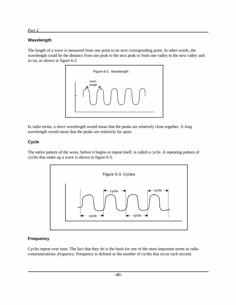
Part 2
-40-
Wavelength
The length of a wave is measured from one point to its next corresponding point. In other words, thewavelength could be the distance from one peak to the next peak or from one valley to the next valley andso on, as shown in figure 6-2.
In radio terms, a short wavelength would mean that the peaks are relatively close together. A longwavelength would mean that the peaks are relatively far apart.
Cycle
The entire pattern of the wave, before it begins to repeat itself, is called a cycle. A repeating pattern ofcycles that make up a wave is shown in figure 6-3.
Frequency
Cycles repeat over time. The fact that they do is the basis for one of the most important terms in radiocommunications: frequency. Frequency is defined as the number of cycles that occur each second.
Figure 6-2. Wavelength
wave-length
Figure 6-3. Cycles
cycle
cycle
cycle
cycle
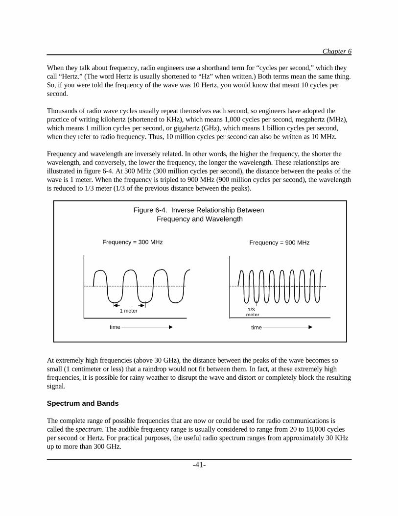
Chapter 6
-41-
When they talk about frequency, radio engineers use a shorthand term for “cycles per second,” which theycall “Hertz.” (The word Hertz is usually shortened to “Hz” when written.) Both terms mean the same thing.So, if you were told the frequency of the wave was 10 Hertz, you would know that meant 10 cycles persecond.
Thousands of radio wave cycles usually repeat themselves each second, so engineers have adopted thepractice of writing kilohertz (shortened to KHz), which means 1,000 cycles per second, megahertz (MHz),which means 1 million cycles per second, or gigahertz (GHz), which means 1 billion cycles per second,when they refer to radio frequency. Thus, 10 million cycles per second can also be written as 10 MHz.
Frequency and wavelength are inversely related. In other words, the higher the frequency, the shorter thewavelength, and conversely, the lower the frequency, the longer the wavelength. These relationships areillustrated in figure 6-4. At 300 MHz (300 million cycles per second), the distance between the peaks of thewave is 1 meter. When the frequency is tripled to 900 MHz (900 million cycles per second), the wavelengthis reduced to 1/3 meter (1/3 of the previous distance between the peaks).
At extremely high frequencies (above 30 GHz), the distance between the peaks of the wave becomes sosmall (1 centimeter or less) that a raindrop would not fit between them. In fact, at these extremely highfrequencies, it is possible for rainy weather to disrupt the wave and distort or completely block the resultingsignal.
Spectrum and Bands
The complete range of possible frequencies that are now or could be used for radio communications iscalled the spectrum. The audible frequency range is usually considered to range from 20 to 18,000 cyclesper second or Hertz. For practical purposes, the useful radio spectrum ranges from approximately 30 KHzup to more than 300 GHz.
Figure 6-4. Inverse Relationship Between Frequency and Wavelength
1/3meter
1 meter
time time
Frequency = 300 MHz Frequency = 900 MHz
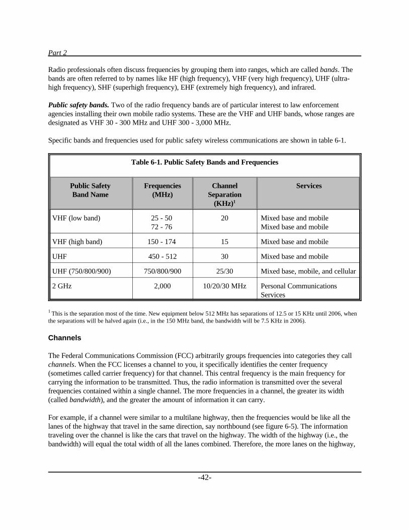
Part 2
-42-
Radio professionals often discuss frequencies by grouping them into ranges, which are called bands. Thebands are often referred to by names like HF (high frequency), VHF (very high frequency), UHF (ultra-high frequency), SHF (superhigh frequency), EHF (extremely high frequency), and infrared.
Public safety bands. Two of the radio frequency bands are of particular interest to law enforcementagencies installing their own mobile radio systems. These are the VHF and UHF bands, whose ranges aredesignated as VHF 30 - 300 MHz and UHF 300 - 3,000 MHz.
Specific bands and frequencies used for public safety wireless communications are shown in table 6-1.
Table 6-1. Public Safety Bands and Frequencies
Public SafetyBand Name
Frequencies(MHz)
ChannelSeparation
(KHz)1
Services
VHF (low band) 25 - 50 72 - 76
20 Mixed base and mobileMixed base and mobile
VHF (high band) 150 - 174 15 Mixed base and mobile
UHF 450 - 512 30 Mixed base and mobile
UHF (750/800/900) 750/800/900 25/30 Mixed base, mobile, and cellular
2 GHz 2,000 10/20/30 MHz Personal CommunicationsServices
1 This is the separation most of the time. New equipment below 512 MHz has separations of 12.5 or 15 KHz until 2006, whenthe separations will be halved again (i.e., in the 150 MHz band, the bandwidth will be 7.5 KHz in 2006).
Channels
The Federal Communications Commission (FCC) arbitrarily groups frequencies into categories they callchannels. When the FCC licenses a channel to you, it specifically identifies the center frequency(sometimes called carrier frequency) for that channel. This central frequency is the main frequency forcarrying the information to be transmitted. Thus, the radio information is transmitted over the severalfrequencies contained within a single channel. The more frequencies in a channel, the greater its width(called bandwidth), and the greater the amount of information it can carry.
For example, if a channel were similar to a multilane highway, then the frequencies would be like all thelanes of the highway that travel in the same direction, say northbound (see figure 6-5). The informationtraveling over the channel is like the cars that travel on the highway. The width of the highway (i.e., thebandwidth) will equal the total width of all the lanes combined. Therefore, the more lanes on the highway,
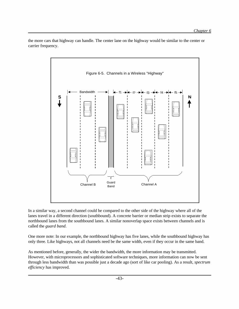
Chapter 6
-43-
the more cars that highway can handle. The center lane on the highway would be similar to the center orcarrier frequency.
In a similar way, a second channel could be compared to the other side of the highway where all of thelanes travel in a different direction (southbound). A concrete barrier or median strip exists to separate thenorthbound lanes from the southbound lanes. A similar nonoverlap space exists between channels and iscalled the guard band.
One more note: In our example, the northbound highway has five lanes, while the southbound highway hasonly three. Like highways, not all channels need be the same width, even if they occur in the same band.
As mentioned before, generally, the wider the bandwidth, the more information may be transmitted.However, with microprocessors and sophisticated software techniques, more information can now be sentthrough less bandwidth than was possible just a decade ago (sort of like car pooling). As a result, spectrumefficiency has improved.
Figure 6-5. Channels in a Wireless "Highway"
Channel B Channel AGuardBand
Bandwidth f1 f2 f3 f4 f5
S N
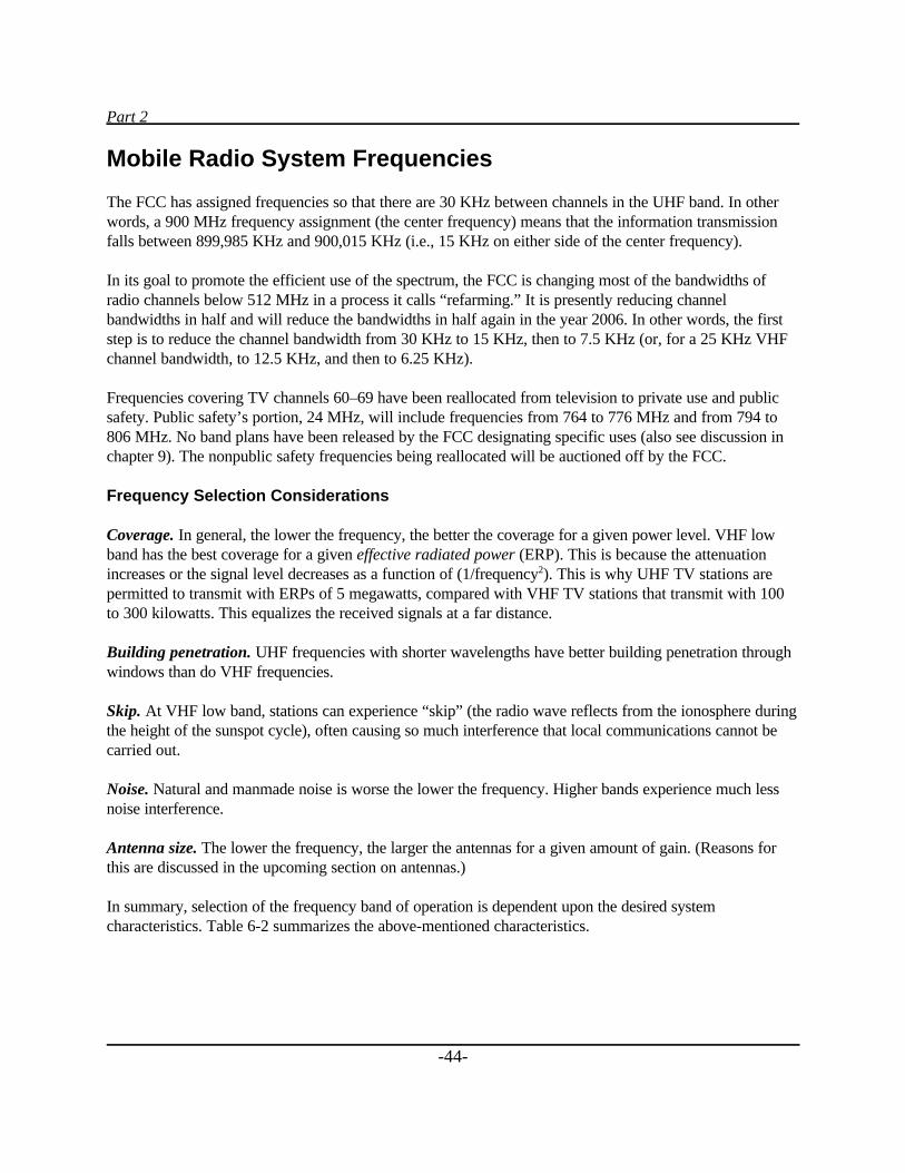
Part 2
-44-
Mobile Radio System Frequencies
The FCC has assigned frequencies so that there are 30 KHz between channels in the UHF band. In otherwords, a 900 MHz frequency assignment (the center frequency) means that the information transmissionfalls between 899,985 KHz and 900,015 KHz (i.e., 15 KHz on either side of the center frequency).
In its goal to promote the efficient use of the spectrum, the FCC is changing most of the bandwidths ofradio channels below 512 MHz in a process it calls “refarming.” It is presently reducing channelbandwidths in half and will reduce the bandwidths in half again in the year 2006. In other words, the firststep is to reduce the channel bandwidth from 30 KHz to 15 KHz, then to 7.5 KHz (or, for a 25 KHz VHFchannel bandwidth, to 12.5 KHz, and then to 6.25 KHz).
Frequencies covering TV channels 60–69 have been reallocated from television to private use and publicsafety. Public safety’s portion, 24 MHz, will include frequencies from 764 to 776 MHz and from 794 to806 MHz. No band plans have been released by the FCC designating specific uses (also see discussion inchapter 9). The nonpublic safety frequencies being reallocated will be auctioned off by the FCC.
Frequency Selection Considerations
Coverage. In general, the lower the frequency, the better the coverage for a given power level. VHF lowband has the best coverage for a given effective radiated power (ERP). This is because the attenuationincreases or the signal level decreases as a function of (1/frequency2). This is why UHF TV stations arepermitted to transmit with ERPs of 5 megawatts, compared with VHF TV stations that transmit with 100to 300 kilowatts. This equalizes the received signals at a far distance.
Building penetration. UHF frequencies with shorter wavelengths have better building penetration throughwindows than do VHF frequencies.
Skip. At VHF low band, stations can experience “skip” (the radio wave reflects from the ionosphere duringthe height of the sunspot cycle), often causing so much interference that local communications cannot becarried out.
Noise. Natural and manmade noise is worse the lower the frequency. Higher bands experience much lessnoise interference.
Antenna size. The lower the frequency, the larger the antennas for a given amount of gain. (Reasons forthis are discussed in the upcoming section on antennas.)
In summary, selection of the frequency band of operation is dependent upon the desired systemcharacteristics. Table 6-2 summarizes the above-mentioned characteristics.
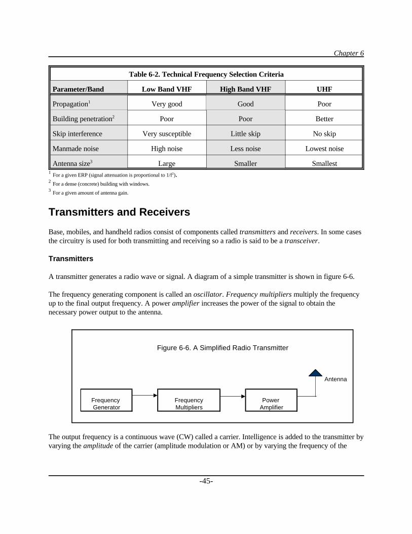
Chapter 6
-45-
Table 6-2. Technical Frequency Selection Criteria
Parameter/Band Low Band VHF High Band VHF UHF
Propagation1 Very good Good Poor
Building penetration2 Poor Poor Better
Skip interference Very susceptible Little skip No skip
Manmade noise High noise Less noise Lowest noise
Antenna size3 Large Smaller Smallest1 For a given ERP (signal attenuation is proportional to 1/f2).2 For a dense (concrete) building with windows.3 For a given amount of antenna gain.
Transmitters and Receivers
Base, mobiles, and handheld radios consist of components called transmitters and receivers. In some casesthe circuitry is used for both transmitting and receiving so a radio is said to be a transceiver.
Transmitters
A transmitter generates a radio wave or signal. A diagram of a simple transmitter is shown in figure 6-6.
The frequency generating component is called an oscillator. Frequency multipliers multiply the frequencyup to the final output frequency. A power amplifier increases the power of the signal to obtain thenecessary power output to the antenna.
The output frequency is a continuous wave (CW) called a carrier. Intelligence is added to the transmitter byvarying the amplitude of the carrier (amplitude modulation or AM) or by varying the frequency of the
Figure 6-6. A Simplified Radio Transmitter
Antenna
Frequency Frequency Power Generator Multipliers Amplifier
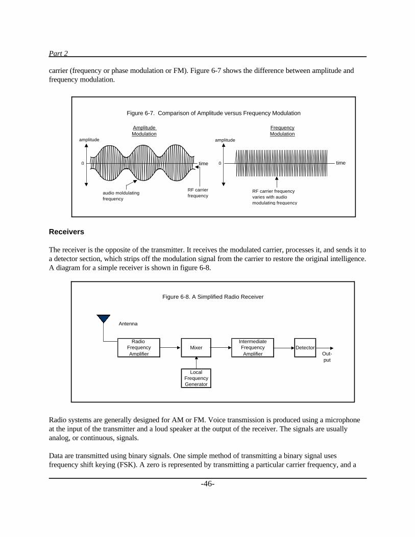
Part 2
-46-
carrier (frequency or phase modulation or FM). Figure 6-7 shows the difference between amplitude andfrequency modulation.
Receivers
The receiver is the opposite of the transmitter. It receives the modulated carrier, processes it, and sends it toa detector section, which strips off the modulation signal from the carrier to restore the original intelligence.A diagram for a simple receiver is shown in figure 6-8.
Radio systems are generally designed for AM or FM. Voice transmission is produced using a microphoneat the input of the transmitter and a loud speaker at the output of the receiver. The signals are usuallyanalog, or continuous, signals.
Data are transmitted using binary signals. One simple method of transmitting a binary signal usesfrequency shift keying (FSK). A zero is represented by transmitting a particular carrier frequency, and a
Antenna
Mixer Detector Out- put
LocalFrequencyGenerator
Amplifier
IntermediateFrequencyAmplifier
Radio Frequency
Figure 6-8. A Simplified Radio Receiver
Figure 6-7. Comparison of Amplitude versus Frequency Modulation
timetime
audio moldulatingfrequency
RF carrierfrequency
RF carrier frequencyvaries with audiomodulating frequency
0 0
amplitude amplitude
Amplitude Modulation
FrequencyModulation
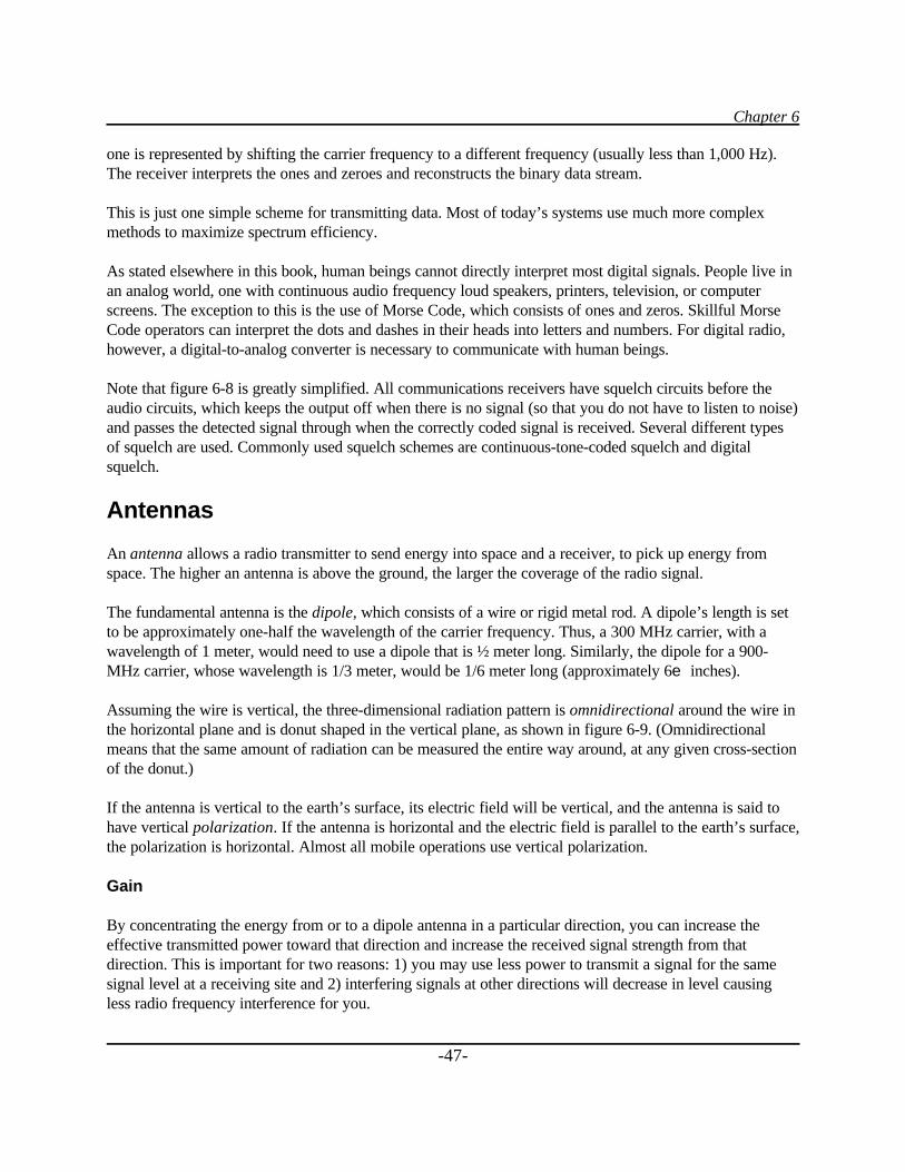
Chapter 6
-47-
one is represented by shifting the carrier frequency to a different frequency (usually less than 1,000 Hz).The receiver interprets the ones and zeroes and reconstructs the binary data stream.
This is just one simple scheme for transmitting data. Most of today’s systems use much more complexmethods to maximize spectrum efficiency.
As stated elsewhere in this book, human beings cannot directly interpret most digital signals. People live inan analog world, one with continuous audio frequency loud speakers, printers, television, or computerscreens. The exception to this is the use of Morse Code, which consists of ones and zeros. Skillful MorseCode operators can interpret the dots and dashes in their heads into letters and numbers. For digital radio,however, a digital-to-analog converter is necessary to communicate with human beings.
Note that figure 6-8 is greatly simplified. All communications receivers have squelch circuits before theaudio circuits, which keeps the output off when there is no signal (so that you do not have to listen to noise)and passes the detected signal through when the correctly coded signal is received. Several different typesof squelch are used. Commonly used squelch schemes are continuous-tone-coded squelch and digitalsquelch.
Antennas
An antenna allows a radio transmitter to send energy into space and a receiver, to pick up energy fromspace. The higher an antenna is above the ground, the larger the coverage of the radio signal.
The fundamental antenna is the dipole, which consists of a wire or rigid metal rod. A dipole’s length is setto be approximately one-half the wavelength of the carrier frequency. Thus, a 300 MHz carrier, with awavelength of 1 meter, would need to use a dipole that is ½ meter long. Similarly, the dipole for a 900-MHz carrier, whose wavelength is 1/3 meter, would be 1/6 meter long (approximately 6e inches).
Assuming the wire is vertical, the three-dimensional radiation pattern is omnidirectional around the wire inthe horizontal plane and is donut shaped in the vertical plane, as shown in figure 6-9. (Omnidirectionalmeans that the same amount of radiation can be measured the entire way around, at any given cross-sectionof the donut.)
If the antenna is vertical to the earth’s surface, its electric field will be vertical, and the antenna is said tohave vertical polarization. If the antenna is horizontal and the electric field is parallel to the earth’s surface,the polarization is horizontal. Almost all mobile operations use vertical polarization.
Gain
By concentrating the energy from or to a dipole antenna in a particular direction, you can increase theeffective transmitted power toward that direction and increase the received signal strength from thatdirection. This is important for two reasons: 1) you may use less power to transmit a signal for the samesignal level at a receiving site and 2) interfering signals at other directions will decrease in level causingless radio frequency interference for you.
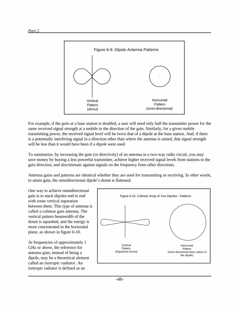
Part 2
-48-
For example, if the gain at a base station is doubled, a user will need only half the transmitter power for thesame received signal strength at a mobile in the direction of the gain. Similarly, for a given mobiletransmitting power, the received signal level will be twice that of a dipole at the base station. And, if thereis a potentially interfering signal in a direction other than where the antenna is aimed, that signal strengthwill be less than it would have been if a dipole were used.
To summarize, by increasing the gain (or directivity) of an antenna in a two-way radio circuit, you maysave money by buying a less powerful transmitter, achieve higher received signal levels from stations in thegain direction, and discriminate against signals on the frequency from other directions.
Antenna gains and patterns are identical whether they are used for transmitting or receiving. In other words,to attain gain, the omnidirectional dipole’s donut is flattened.
One way to achieve omnidirectionalgain is to stack dipoles end to endwith some vertical separationbetween them. This type of antenna iscalled a colinear gain antenna. Thevertical pattern beamwidth of thedonut is squashed, and the energy ismore concentrated in the horizontalplane, as shown in figure 6-10.
At frequencies of approximately 1GHz or above, the reference forantenna gain, instead of being adipole, may be a theoretical elementcalled an isotropic radiator. Anisotropic radiator is defined as an
Figure 6-9. Dipole Antenna Patterns
.
VerticalPattern(donut)
HorizontalPattern
(omni-directional)
Figure 6-10. Colinear Array of Two Dipoles - Patterns
.
HorizontalPattern
(omni-directional twice radius ofthe dipole)
VerticalPattern
(Squashed Donut)
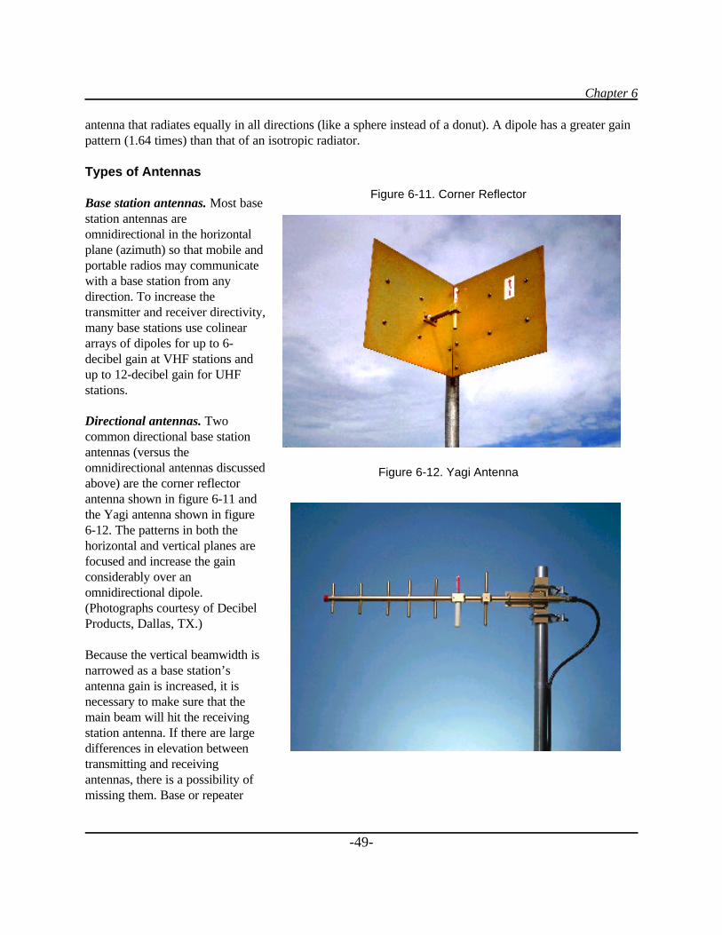
Chapter 6
-49-
Figure 6-11. Corner Reflector
Figure 6-12. Yagi Antenna
antenna that radiates equally in all directions (like a sphere instead of a donut). A dipole has a greater gainpattern (1.64 times) than that of an isotropic radiator.
Types of Antennas
Base station antennas. Most basestation antennas areomnidirectional in the horizontalplane (azimuth) so that mobile andportable radios may communicatewith a base station from anydirection. To increase thetransmitter and receiver directivity,many base stations use colineararrays of dipoles for up to 6-decibel gain at VHF stations andup to 12-decibel gain for UHFstations.
Directional antennas. Twocommon directional base stationantennas (versus theomnidirectional antennas discussedabove) are the corner reflectorantenna shown in figure 6-11 andthe Yagi antenna shown in figure6-12. The patterns in both thehorizontal and vertical planes arefocused and increase the gainconsiderably over anomnidirectional dipole.(Photographs courtesy of DecibelProducts, Dallas, TX.)
Because the vertical beamwidth isnarrowed as a base station’santenna gain is increased, it isnecessary to make sure that themain beam will hit the receivingstation antenna. If there are largedifferences in elevation betweentransmitting and receivingantennas, there is a possibility ofmissing them. Base or repeater
Part 2
-50-
stations that are placed on very tall buildings or on mountaintops often are designed with a “downtilt” ontheir patterns to make sure that the maximum radiation hits close-in mobile units.
Mobile antennas. The simplest mobile antenna is a quarter-wave whip antenna. It consists of a singlevertical element, approximately 1/4 wavelength long, mounted onto the metal roof of an automobile, and iscalled a monopole.
The roof acts as a “ground plane” reflector so that the antenna radiation pattern emulates a dipole antenna.
At VHF low band (50 MHz), a quarter wave monopole antenna is about 5 feet long. As the frequency isincreased, the length of a monopole antenna is reduced. At 850 MHz, a monopole is only 3.5 inches long.
Portable antennas. Portable radios usually use helically wound or rod antennas attached to the radio.These are usually less efficient than base or mobile antennas. There are also times when your body isbetween the portable and the base with which it is communicating, causing a decrease in signal. Thesecharacteristics must be accounted for in designing a system.
Smart antennas. A new type of antenna used for receivers at cellular and personal communicationssystems (PCS) sites is called a “smart antenna.” Smart receiving antennas have the ability to focus on areceived signal so that it obtains both maximum gain and interference suppression from other signals on thesame channel. In other words, the gain of a smart antenna is varied using computer technology toward aparticular station to attain the highest received signal level and to discriminate against interfering signals.Smart antennas are generally expensive.
Interference
With the advent of cellular, PCS, specialized mobile radio (SMR) and enhanced specialized mobile radio(ESMR) systems, many new antenna installations must be made throughout the country. To minimize thenumber of new antenna sites (and associated towers), installations with a multitude of radios combined on afew antennas are becoming more prevalent.
As the number of radios and antennas is increased at a site, the interference potential of generating and/orreceiving spurious signals is increased. Therefore, filters and isolators (discussed in the next section) mustbe added to the antenna circuits. Usually, the last station to build at the site causes the interference and isresponsible for the additional filtering equipment. Some sites have full-time managers who screen anapplicant’s plans to anticipate any interference potential.
Interference may be predicted using a software program by inputting the transmitted signal frequencies andbandwidths and the receiver frequencies and bandwidths. This allows you to determine the intermodulationproduct frequencies and harmonics that might be generated externally or internally in the equipment.Knowing what may be expected allows you to take preventive action. Some types of filters used arediscussed in the duplexers, combiners, and multicouplers sections of this book.
Chapter 6
-51-
Radiation
Additionally, with high-power transmitter stations there is the potential problem of harmful radiation.Service personnel climbing towers in the vicinity of radiating antennas could be exposed to large amountsof radiation, which can cause excessive skin and body tissue heating or burns. It may be necessary toreduce power or turn off transmitters when these technicians are climbing.
The radiation danger is highest when there are high-power broadcast stations at common sites. Alsoradiation exposure requirements for the public are less than for personnel associated with the site (see table9-1 in chapter 9). To help prevent public exposure, security fences usually are constructed around towers,and the fences are posted with “Hazardous RF” signs.
Local Regulations Controlling Antennas
Most cities have zoning ordinances that control the use of land for radio sites. These usually includemaximum tower heights and setbacks, as well as the antenna types and radiation characteristics. Usually anapplication for a radio site is prepared by an applicant and submitted to the zoning board for processingand a recommendation. County commissioners or city council members have the final approval. Membersof the public often have the opportunity to voice their opinions regarding the aesthetics and requested use ofthe site before approval. It is not unusual for a government entity to add stipulations for disguising a towerand antenna. Recent examples include requiring a tower to look like a tree and using a church steeple tohouse an antenna.
Radio Coverage
One of the most important characteristics of a radio system is its coverage. That is, it is important to knowexactly where the base or repeater station signals may be received by mobile or handheld radios and exactlywhere mobile or handheld radio stations may be heard by a base or repeater station.
All parameters must be placed into one of several computer models (called propagation models) to get areasonably accurate output. These include transmitter power out, transmission line losses, antenna gain anddirectivity, foliage losses, building losses (if required), receiver sensitivity, and antenna and transmissionline characteristics.
Figure 6-13 shows a typical coverage pattern for a base station (the large black area). Notice that there aresome holes in the main contour (white areas within the black area) where signals are not heard, and thereare some places (hills) outside of the main contour where there is reception.
These coverage maps, or contour diagrams, are usually made using one of a number of theoreticalpropagation programs and then running field tests to correct the uncertainty in the models.
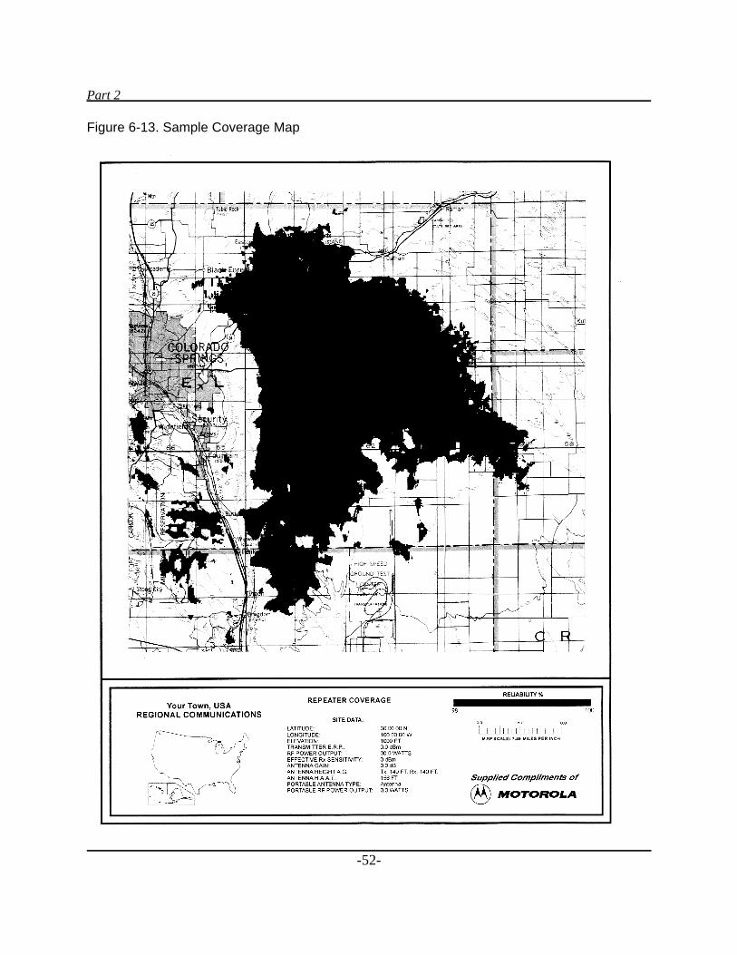
Part 2
-52-
Figure 6-13. Sample Coverage Map
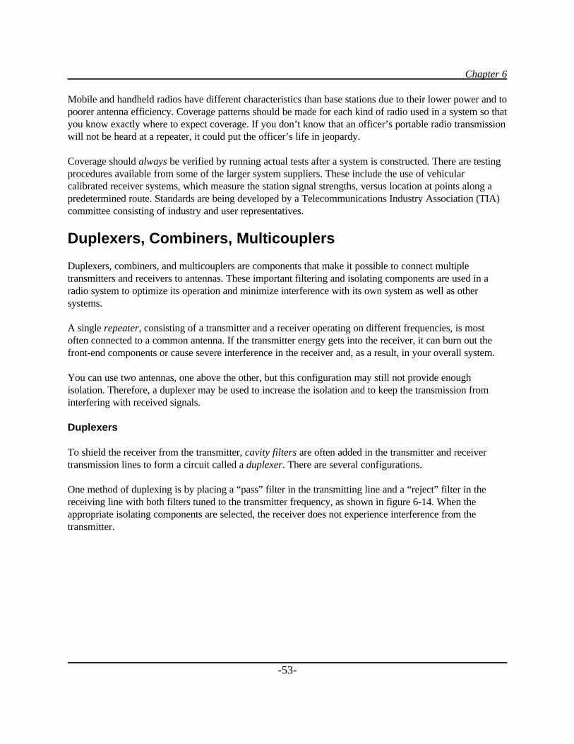
Chapter 6
-53-
Mobile and handheld radios have different characteristics than base stations due to their lower power and topoorer antenna efficiency. Coverage patterns should be made for each kind of radio used in a system so thatyou know exactly where to expect coverage. If you don’t know that an officer’s portable radio transmissionwill not be heard at a repeater, it could put the officer’s life in jeopardy.
Coverage should always be verified by running actual tests after a system is constructed. There are testingprocedures available from some of the larger system suppliers. These include the use of vehicularcalibrated receiver systems, which measure the station signal strengths, versus location at points along apredetermined route. Standards are being developed by a Telecommunications Industry Association (TIA)committee consisting of industry and user representatives.
Duplexers, Combiners, Multicouplers
Duplexers, combiners, and multicouplers are components that make it possible to connect multipletransmitters and receivers to antennas. These important filtering and isolating components are used in aradio system to optimize its operation and minimize interference with its own system as well as othersystems.
A single repeater, consisting of a transmitter and a receiver operating on different frequencies, is mostoften connected to a common antenna. If the transmitter energy gets into the receiver, it can burn out thefront-end components or cause severe interference in the receiver and, as a result, in your overall system.
You can use two antennas, one above the other, but this configuration may still not provide enoughisolation. Therefore, a duplexer may be used to increase the isolation and to keep the transmission frominterfering with received signals.
Duplexers
To shield the receiver from the transmitter, cavity filters are often added in the transmitter and receivertransmission lines to form a circuit called a duplexer. There are several configurations.
One method of duplexing is by placing a “pass” filter in the transmitting line and a “reject” filter in thereceiving line with both filters tuned to the transmitter frequency, as shown in figure 6-14. When theappropriate isolating components are selected, the receiver does not experience interference from thetransmitter.
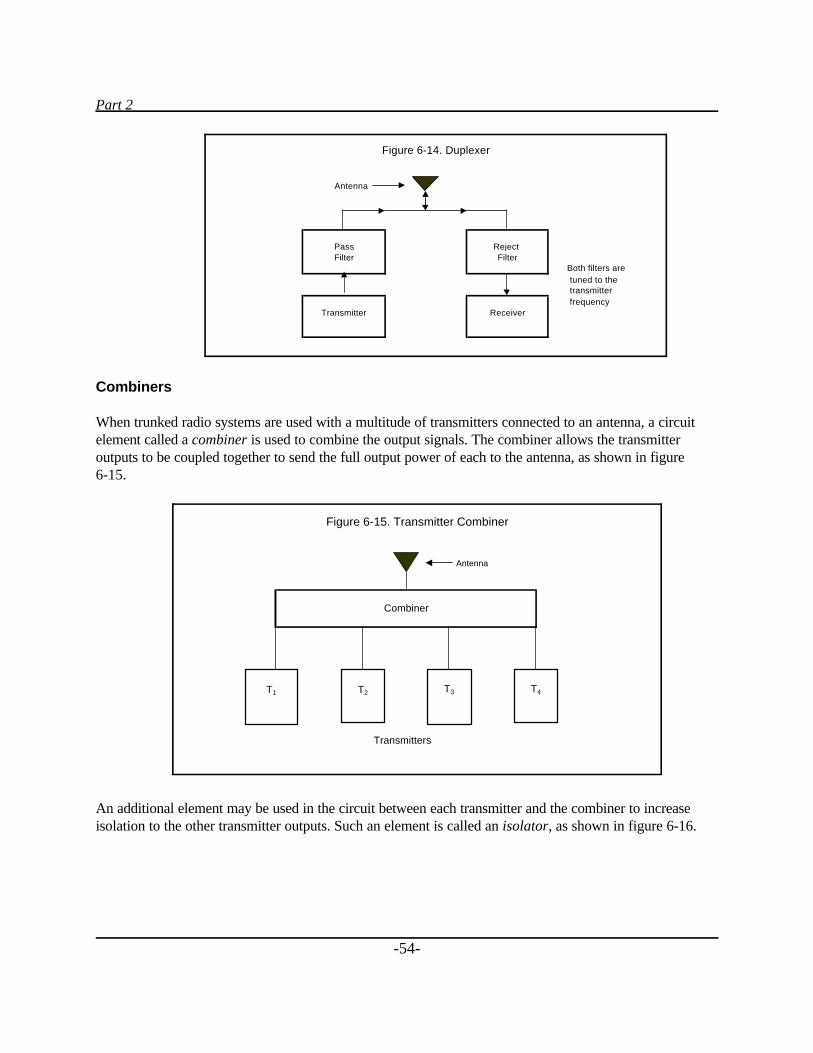
Part 2
-54-
Combiners
When trunked radio systems are used with a multitude of transmitters connected to an antenna, a circuitelement called a combiner is used to combine the output signals. The combiner allows the transmitteroutputs to be coupled together to send the full output power of each to the antenna, as shown in figure 6-15.
An additional element may be used in the circuit between each transmitter and the combiner to increaseisolation to the other transmitter outputs. Such an element is called an isolator, as shown in figure 6-16.
Antenna
Both filters are tuned to the transmitter frequency
Figure 6-14. Duplexer
PassFilter
Transmitter
Reject Filter
Receiver
Antenna
Figure 6-15. Transmitter Combiner
Combiner
Transmitters
T1 T2 T3 T4
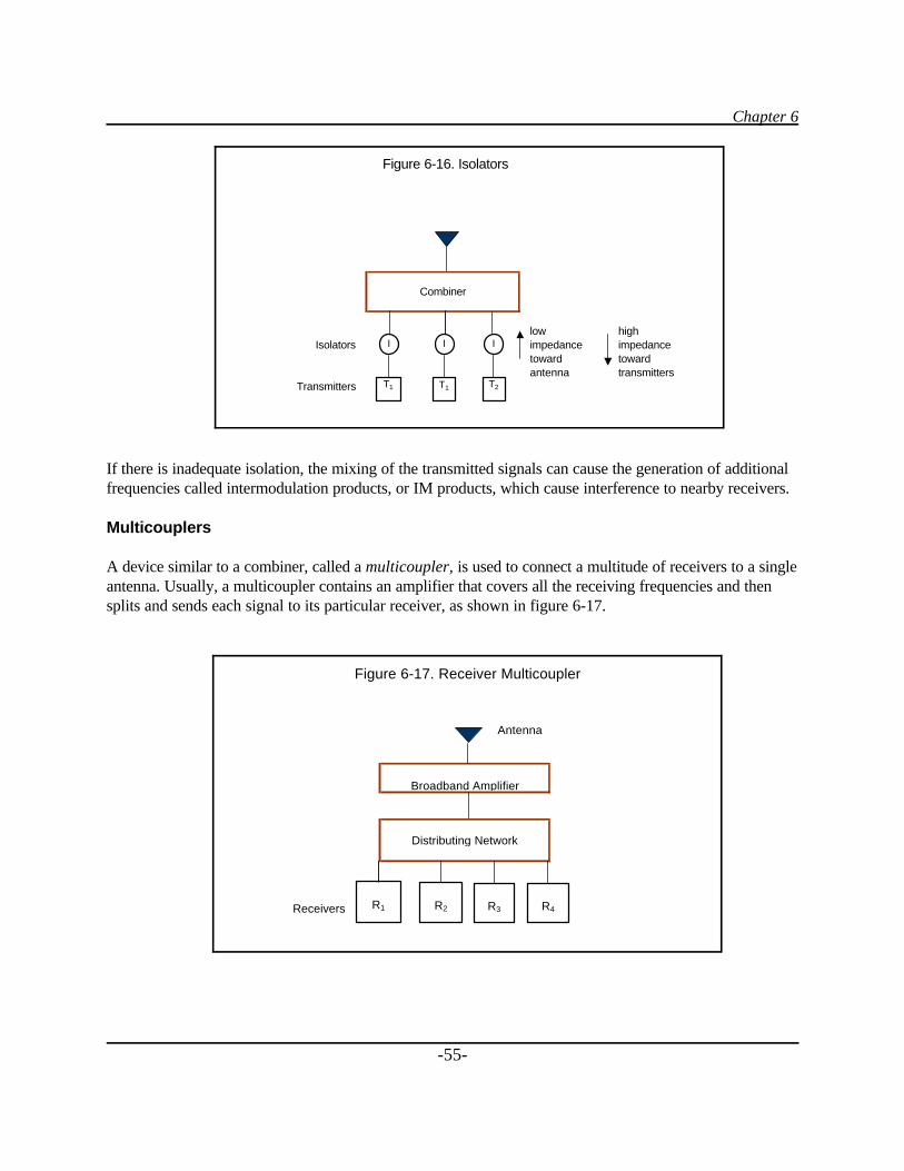
Chapter 6
-55-
If there is inadequate isolation, the mixing of the transmitted signals can cause the generation of additionalfrequencies called intermodulation products, or IM products, which cause interference to nearby receivers.
Multicouplers
A device similar to a combiner, called a multicoupler, is used to connect a multitude of receivers to a singleantenna. Usually, a multicoupler contains an amplifier that covers all the receiving frequencies and thensplits and sends each signal to its particular receiver, as shown in figure 6-17.
low highIsolators impedance impedance
toward toward antenna transmitters
Transmitters
Figure 6-16. Isolators
Combiner
I I
T1 T2
I
T1
Antenna
Receivers
Figure 6-17. Receiver Multicoupler
Distributing Network
Broadband Amplifier
R1 R3R2 R4
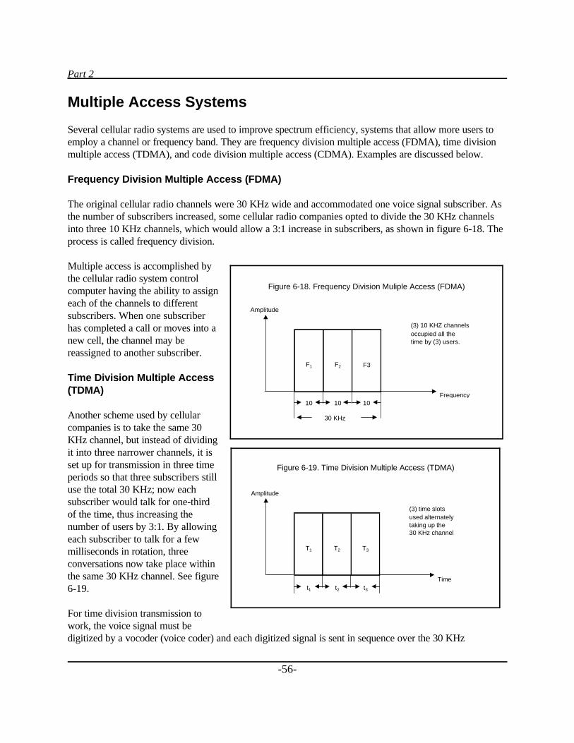
Part 2
-56-
Multiple Access Systems
Several cellular radio systems are used to improve spectrum efficiency, systems that allow more users toemploy a channel or frequency band. They are frequency division multiple access (FDMA), time divisionmultiple access (TDMA), and code division multiple access (CDMA). Examples are discussed below.
Frequency Division Multiple Access (FDMA)
The original cellular radio channels were 30 KHz wide and accommodated one voice signal subscriber. Asthe number of subscribers increased, some cellular radio companies opted to divide the 30 KHz channelsinto three 10 KHz channels, which would allow a 3:1 increase in subscribers, as shown in figure 6-18. Theprocess is called frequency division.
Multiple access is accomplished bythe cellular radio system controlcomputer having the ability to assigneach of the channels to differentsubscribers. When one subscriberhas completed a call or moves into anew cell, the channel may bereassigned to another subscriber.
Time Division Multiple Access(TDMA)
Another scheme used by cellularcompanies is to take the same 30KHz channel, but instead of dividingit into three narrower channels, it isset up for transmission in three timeperiods so that three subscribers stilluse the total 30 KHz; now eachsubscriber would talk for one-thirdof the time, thus increasing thenumber of users by 3:1. By allowingeach subscriber to talk for a fewmilliseconds in rotation, threeconversations now take place withinthe same 30 KHz channel. See figure6-19.
For time division transmission towork, the voice signal must bedigitized by a vocoder (voice coder) and each digitized signal is sent in sequence over the 30 KHz
Amplitude
(3) 10 KHZ channelsoccupied all the time by (3) users.
F1 F2 F3
Frequency10 10 10
30 KHz
Figure 6-18. Frequency Division Muliple Access (FDMA)
Amplitude
(3) time slots used alternatelytaking up the30 KHz channel
T1 T2 T3
Timet1 t2 t3
Figure 6-19. Time Division Multiple Access (TDMA)
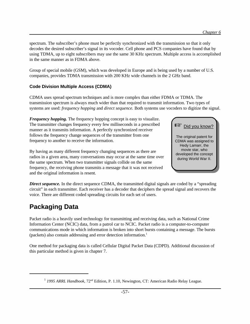
Chapter 6
1 1995 ARRL Handbook, 72nd Edition, P. 1.10, Newington, CT: American Radio Relay League.
-57-
spectrum. The subscriber’s phone must be perfectly synchronized with the transmission so that it onlydecodes the desired subscriber’s signal in its vocoder. Cell phone and PCS companies have found that byusing TDMA, up to eight subscribers may use the same 30 KHz spectrum. Multiple access is accomplishedin the same manner as in FDMA above.
Group of special mobile (GSM), which was developed in Europe and is being used by a number of U.S.companies, provides TDMA transmission with 200 KHz wide channels in the 2 GHz band.
Code Division Multiple Access (CDMA)
CDMA uses spread spectrum techniques and is more complex than either FDMA or TDMA. Thetransmission spectrum is always much wider than that required to transmit information. Two types ofsystems are used: frequency hopping and direct sequence. Both systems use vocoders to digitize the signal.
Frequency hopping. The frequency hopping concept is easy to visualize.The transmitter changes frequency every few milliseconds in a prescribedmanner as it transmits information. A perfectly synchronized receiverfollows the frequency change sequences of the transmitter from onefrequency to another to receive the information.
By having as many different frequency changing sequences as there areradios in a given area, many conversations may occur at the same time overthe same spectrum. When two transmitter signals collide on the samefrequency, the receiving phone transmits a message that it was not receivedand the original information is resent.
Direct sequence. In the direct sequence CDMA, the transmitted digital signals are coded by a “spreadingcircuit” in each transmitter. Each receiver has a decoder that deciphers the spread signal and recovers thevoice. There are different coded spreading circuits for each set of users.
Packaging Data
Packet radio is a heavily used technology for transmitting and receiving data, such as National CrimeInformation Center (NCIC) data, from a patrol car to NCIC. Packet radio is a computer-to-computercommunications mode in which information is broken into short bursts containing a message. The bursts(packets) also contain addressing and error detection information.1
One method for packaging data is called Cellular Digital Packet Data (CDPD). Additional discussion ofthis particular method is given in chapter 7.
L Did you know?
The original patent forCDMA was assigned to
Hedy Lamarr, themovie star, who
developed the conceptduring World War II.
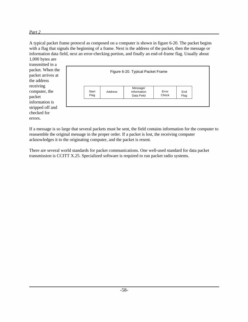
Part 2
-58-
A typical packet frame protocol as composed on a computer is shown in figure 6-20. The packet beginswith a flag that signals the beginning of a frame. Next is the address of the packet, then the message orinformation data field, next an error-checking portion, and finally an end-of-frame flag. Usually about1,000 bytes aretransmitted in apacket. When thepacket arrives atthe addressreceivingcomputer, thepacketinformation isstripped off andchecked forerrors.
If a message is so large that several packets must be sent, the field contains information for the computer toreassemble the original message in the proper order. If a packet is lost, the receiving computeracknowledges it to the originating computer, and the packet is resent.
There are several world standards for packet communications. One well-used standard for data packettransmission is CCITT X.25. Specialized software is required to run packet radio systems.
Figure 6-20. Typical Packet Frame
Message/InformationData Field
Address ErrorCheck
StartFlag
End Flag
Chapter 7
-59-
Chapter 7_____
Current Public Safety Radio Systems
Paging Systems
Paging systems are single-frequency, one-way radio systems used for making people aware that they arebeing sought. The original local government pagers were voice pagers used for calling out volunteer firedepartments (many of which are still in use). Modern pagers have alphanumeric readouts and are capableof storing a number of messages. Pagers are used by volunteer fire departments, police officers, emergencymedical personnel, service personnel and technicians, and even children whose parents wish to keep track ofthem.
Very reliable commercial paging services are available in most regions of the United States at reasonablesubscription rates. Many are used by local police, fire, and emergency medical services (EMS) units.
Alerts are given by a tone or a set of tones or by a built-in vibrator for use where tones are not permissible.There are many local and national suppliers of paging services and pagers.
Paging is accomplished at many different frequency bands including VHF, UHF, and FM broadcast. Twostandards are especially popular at this time, but many others exist. These include the British Post Officestandard, called POCSAG (Post Office Code Standardization Advisory Group), and Motorola’s FLEX™system.
Statewide and nationwide paging is accomplished by transmitting the paging information over telephonelines or via satellites to paging transmitters for retransmission. When it is necessary to page over a widearea, a multitude of paging transmitters are activated at the same time in a simulcasting fashion.
The FCC has auctioned off a number of pairs of frequencies for two-way paging in the 800 MHz band(PCS narrowband). Each uses a 50 KHz bandwidth in one direction to accommodate high-speed datatransmission, which is paired with either 50 KHz or 12.5 KHz in the reverse direction for returning data.The FCC also authorized some paging response frequencies for paging users who are already licensedunder parts 22 and 90 of the FCC Rules, under certain circumstances.
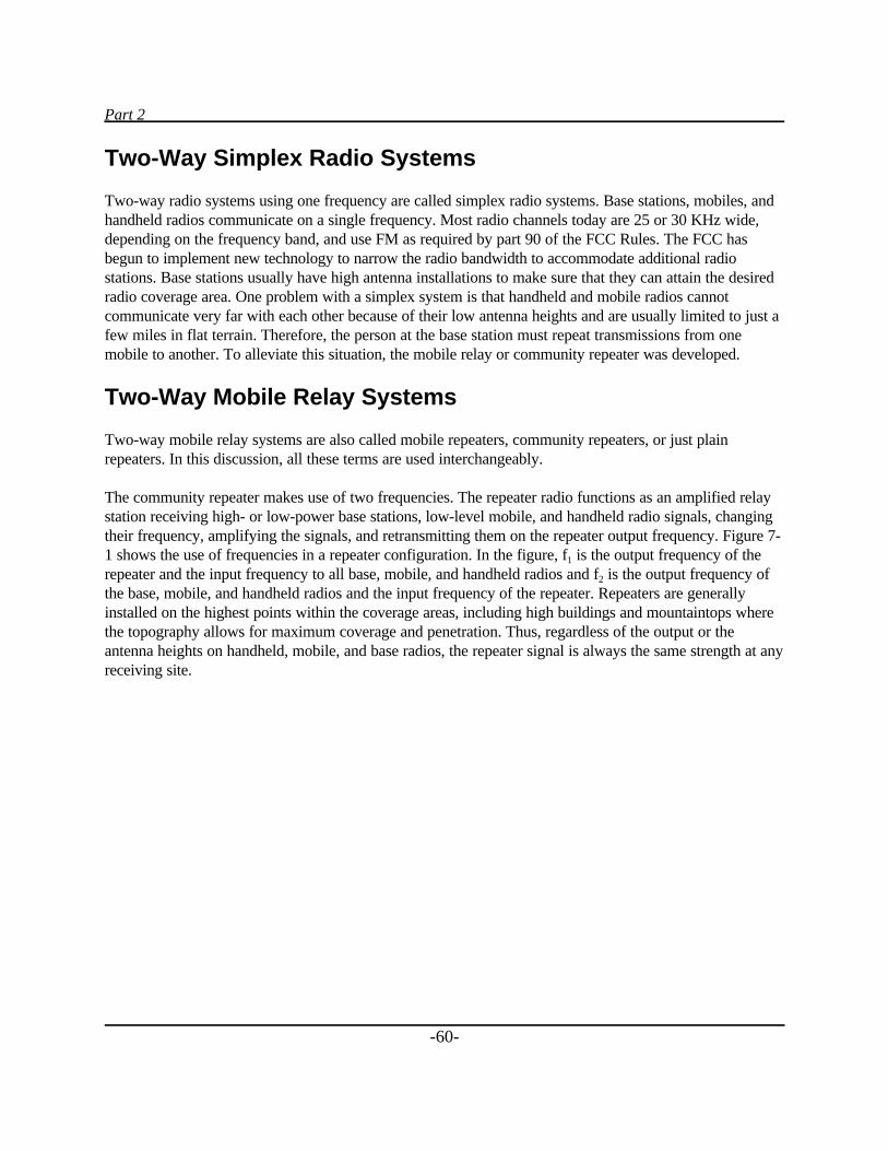
Part 2
-60-
Two-Way Simplex Radio Systems
Two-way radio systems using one frequency are called simplex radio systems. Base stations, mobiles, andhandheld radios communicate on a single frequency. Most radio channels today are 25 or 30 KHz wide,depending on the frequency band, and use FM as required by part 90 of the FCC Rules. The FCC hasbegun to implement new technology to narrow the radio bandwidth to accommodate additional radiostations. Base stations usually have high antenna installations to make sure that they can attain the desiredradio coverage area. One problem with a simplex system is that handheld and mobile radios cannotcommunicate very far with each other because of their low antenna heights and are usually limited to just afew miles in flat terrain. Therefore, the person at the base station must repeat transmissions from onemobile to another. To alleviate this situation, the mobile relay or community repeater was developed.
Two-Way Mobile Relay Systems
Two-way mobile relay systems are also called mobile repeaters, community repeaters, or just plainrepeaters. In this discussion, all these terms are used interchangeably.
The community repeater makes use of two frequencies. The repeater radio functions as an amplified relaystation receiving high- or low-power base stations, low-level mobile, and handheld radio signals, changingtheir frequency, amplifying the signals, and retransmitting them on the repeater output frequency. Figure 7-1 shows the use of frequencies in a repeater configuration. In the figure, f1 is the output frequency of therepeater and the input frequency to all base, mobile, and handheld radios and f2 is the output frequency ofthe base, mobile, and handheld radios and the input frequency of the repeater. Repeaters are generallyinstalled on the highest points within the coverage areas, including high buildings and mountaintops wherethe topography allows for maximum coverage and penetration. Thus, regardless of the output or theantenna heights on handheld, mobile, and base radios, the repeater signal is always the same strength at anyreceiving site.
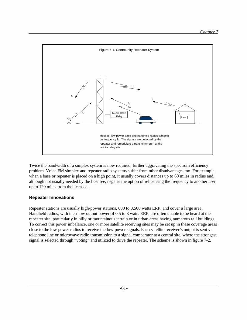
Chapter 7
-61-
Twice the bandwidth of a simplex system is now required, further aggravating the spectrum efficiencyproblem. Voice FM simplex and repeater radio systems suffer from other disadvantages too. For example,when a base or repeater is placed on a high point, it usually covers distances up to 60 miles in radius and,although not usually needed by the licensee, negates the option of relicensing the frequency to another userup to 120 miles from the licensee.
Repeater Innovations
Repeater stations are usually high-power stations, 600 to 3,500 watts ERP, and cover a large area.Handheld radios, with their low output power of 0.5 to 3 watts ERP, are often unable to be heard at therepeater site, particularly in hilly or mountainous terrain or in urban areas having numerous tall buildings.To correct this power imbalance, one or more satellite receiving sites may be set up in these coverage areasclose to the low-power radios to receive the low-power signals. Each satellite receiver’s output is sent viatelephone line or microwave radio transmission to a signal comparator at a central site, where the strongestsignal is selected through “voting” and utilized to drive the repeater. The scheme is shown in figure 7-2.
f1
f1 f2
f2
f2
f2 Mobile RadioRelay
Mobiles, low power base and handheld radios transmiton frequency f2. The signals are detected by the
repeater and remodulate a transmitter on f1 at themobile relay site.
Figure 7-1. Community Repeater System
Base
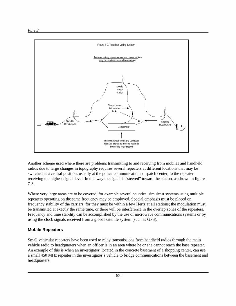
Part 2
-62-
Another scheme used where there are problems transmitting to and receiving from mobiles and handheldradios due to large changes in topography requires several repeaters at different locations that may beswitched at a central position, usually at the police communications dispatch center, to the repeaterreceiving the highest signal level. In this way the signal is “steered” toward the station, as shown in figure7-3.
Where very large areas are to be covered, for example several counties, simulcast systems using multiplerepeaters operating on the same frequency may be employed. Special emphasis must be placed onfrequency stability of the carriers, for they must be within a few Hertz at all stations; the modulation mustbe transmitted at exactly the same time, or there will be interference in the overlap zones of the repeaters.Frequency and time stability can be accomplished by the use of microwave communications systems or byusing the clock signals received from a global satellite system (such as GPS).
Mobile Repeaters
Small vehicular repeaters have been used to relay transmissions from handheld radios through the mainvehicle radio to headquarters when an officer is in an area where he or she cannot reach the base repeater.An example of this is when an investigator, located in the concrete basement of a shopping center, can usea small 450 MHz repeater in the investigator’s vehicle to bridge communications between the basement andheadquarters.
Comparator
MobileRelay
Station
Telephone orMicrowave
Links
The comparator votes the strongestreceived signal as the one heard at
the mobile relay station.
SatelliteReceiver #1
SatelliteReceiver #2
Figure 7-2. Receiver Voting System
Receiver voting system where low power stationsmay be received on satellite receivers.
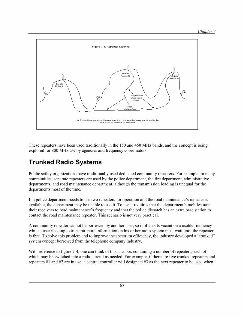
Chapter 7
-63-
These repeaters have been used traditionally in the 150 and 450 MHz bands, and the concept is beingexplored for 800 MHz use by agencies and frequency coordinators.
Trunked Radio SystemsPublic safety organizations have traditionally used dedicated community repeaters. For example, in manycommunities, separate repeaters are used by the police department, the fire department, administrativedepartments, and road maintenance department, although the transmission loading is unequal for thedepartments most of the time.
If a police department needs to use two repeaters for operation and the road maintenance’s repeater isavailable, the department may be unable to use it. To use it requires that the department’s mobiles tunetheir receivers to road maintenance’s frequency and that the police dispatch has an extra base station tocontact the road maintenance repeater. This scenario is not very practical.
A community repeater cannot be borrowed by another user, so it often sits vacant on a usable frequencywhile a user needing to transmit more information on his or her radio system must wait until the repeateris free. To solve this problem and to improve the spectrum efficiency, the industry developed a “trunked”system concept borrowed from the telephone company industry.
With reference to figure 7-4, one can think of this as a box containing a number of repeaters, each ofwhich may be switched into a radio circuit as needed. For example, if there are five trunked repeaters andrepeaters #1 and #2 are in use, a central controller will designate #3 as the next repeater to be used when
PoliceHeadquarters
MobileRelay #3
MobileRelay #2
Telephone orMicrowave
Links
MobileRelay #1
Figure 7-3. Repeater Steering
At Police Headquarters, the repeater that receives the strongest signal is theone used to transmit to that user.
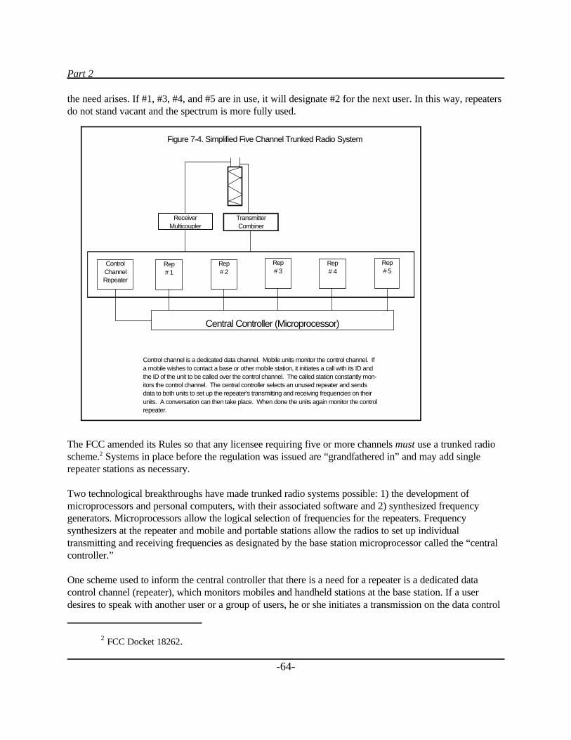
Part 2
2 FCC Docket 18262.
-64-
the need arises. If #1, #3, #4, and #5 are in use, it will designate #2 for the next user. In this way, repeatersdo not stand vacant and the spectrum is more fully used.
The FCC amended its Rules so that any licensee requiring five or more channels must use a trunked radioscheme.2 Systems in place before the regulation was issued are “grandfathered in” and may add singlerepeater stations as necessary.
Two technological breakthroughs have made trunked radio systems possible: 1) the development ofmicroprocessors and personal computers, with their associated software and 2) synthesized frequencygenerators. Microprocessors allow the logical selection of frequencies for the repeaters. Frequencysynthesizers at the repeater and mobile and portable stations allow the radios to set up individualtransmitting and receiving frequencies as designated by the base station microprocessor called the “centralcontroller.”
One scheme used to inform the central controller that there is a need for a repeater is a dedicated datacontrol channel (repeater), which monitors mobiles and handheld stations at the base station. If a userdesires to speak with another user or a group of users, he or she initiates a transmission on the data control
Figure 7-4. Simplified Five Channel Trunked Radio System
TransmitterCombiner
Control channel is a dedicated data channel. Mobile units monitor the control channel. Ifa mobile wishes to contact a base or other mobile station, it initiates a call with its ID and the ID of the unit to be called over the control channel. The called station constantly mon-itors the control channel. The central controller selects an unused repeater and sends data to both units to set up the repeater's transmitting and receiving frequencies on their units. A conversation can then take place. When done the units again monitor the controlrepeater.
ControlChannelRepeater
Rep # 1
Rep # 2
Rep# 3
Rep# 4
Rep# 5
Central Controller (Microprocessor)
ReceiverMulticoupler
Chapter 7
-65-
channel indicating his or her ID number and requesting that he or she talk with another user or a group ofusers by indicating the group’s or individual’s ID number. The control channel repeater acknowledges thetransmission, and the central controller determines the available repeater and commands the initiator andthe target station(s) to change their operating frequencies to that of the assigned repeater. A voiceconversation may then take place. After the conversation, the radios return to monitoring the controlchannel and the central controller determines that the repeater is now available for other use. Note thatthese systems are totally software driven.
Besides dedicating a single repeater for control, there are other schemes that can be used. For example, thecontrol channel may be rotated from one channel to another. Each time it is moved, the subscriber’s unitsmust change frequency and track it.
Trunked radio systems are generally used in the 800/900 MHz bands. The latest FCC Rules now allow forVHF trunking systems to be developed, provided that they do not interfere with existing radio systems insurrounding areas.
Major suppliers of trunked radio systems are Motorola, ComNet Ericsson Critical Radio Systems, and theE.F. Johnson® Division of Transcrypt.
Specialized Mobile Radio (SMR)
Besides local government and law enforcement, trunked radio systems are used by large electric, gas, oil,and other industries to improve their efficiencies. A specific class of service, called “specialized mobileradio” was designated by the FCC to allow the set up of trunked systems that could be used to sell radioservices to commercial and government users. The authors discuss these offerings later in this book as areliable option, where available, for law enforcement.
The channel bandwidth set up for trunked activities is 30 KHz wide in the 800/900 MHz band. Originalapplicants used analog radios; however, enhanced specialized mobile radio has been the name given fordigital SMR systems. Nextel is one supplier providing ESMR services nationally. Commercial services oftrunked SMRs and ESMRs also are examined later in this guidebook.
APCO Project 16 Trunked Radio System
The Law Enforcement Assistance Administration (LEAA) in 1977 provided a grant to the Association ofPublic-Safety Communications Officials-International (APCO) to make possible the opportunity for thepublic safety community to develop test beds and study various parameters associated with UHF bandtrunking systems.
APCO Project 16 members were charged with evaluating the technical, economic, and regulatory questionsraised by the 800/900 MHz spectrum made available by the FCC. Studies were made on three experimentalsystems in Chicago, Miami, and Orange County, California.
Part 2
3 APCO, 900 MHz Trunked Communications System Functional Requirements Development, Executive
Summary, March 1979.
-66-
When the study was completed, APCO published a document defining the mandatory and desirablefunctional capabilities for a public safety analog trunked radio system. It was issued in March 1979 andwas called 900 MHz Trunked Communications System Functional Requirements Development. Therequirements were tailored for law enforcement and addressed channel access times, automated priorityrecognition, data systems interface, individuality of system users, command/control flexibility, systemsgrowth capability, frequency utilization, and reliability.3
APCO 16 systems are presently being used by most large and medium-sized government agencies. To makethe technology available to smaller government groups in adjoining cities, some communities are sharingsystems. This has cut down on both capital investment and operating costs by any single entity.
The APCO 16 specification had no interoperability or encryption requirements; thus systems supplied bydifferent manufacturers do not talk to one another. This limits competitive bidding for expansion andreplacement parts.
A new digital system specification, under the APCO Project 25 Committee, has been in process for years tocorrect some of the interoperability difficulties, improve spectrum efficiency, and take into account thechanging world to more efficiently and economically manufacture digital radio systems.
APCO Project 25 Digital Trunked Radio System
APCO formed a working group called APCO Project 25 (now called simply Project 25) for thedevelopment of a digitally trunked radio system specification tailored to public safety needs. Associationsand agencies including the National Association of State Telecommunications Directors (NASTD),National Telecommunications and Information Agency (NTIA), National Communications System (NCS),Department of Defense (DoD), APCO Canada, and British Home Office were brought into the process toobtain as many contributions as possible to make the resulting specification a world standard for digitalland public safety mobile radio. The Telecommunications Industry Association has been involved with theProject 25 group by providing technical support and the mechanics of standards writing, which has madethe resulting specification (ANSI/TIA 102) into the national industry standard.
The objectives of Project 25 are: to maximize spectrum efficiency; to ensure competition in life cycleprocurements; to allow effective and efficient inter- and intra-agency communications; and to provide“user-friendly” equipment and operation. Services defined include digital voice address includingindividual, group, and broadcast calls; circuit data including protected and unprotected data, packet data,and a set of nine supplementary services including encryption. Both conventional and trunked air interfacespecifications are included. The specification will be used for unit-to-unit direct communications, basestation to limited field units, multisite simulcast, voting receiver systems, and wide and local area trunkingat frequencies from 100 to 1000 MHz.
Chapter 7
-67-
As stated above, the APCO Project 16 standard resulted in a number of competing analog systems thatwere unable to communicate with one another, and high on Project 25’s list of requirements is a commonair interface between systems of different manufacturers enabling interoperability. In addition, there arecommon interfaces spelled out for the data port for laptop and other terminals, the host computer and othernetworks, the public telephone system interconnect, the network manager, and for connecting multiplesystems (inter-system). Thus, competing companies may design their own offerings provided the commoninterface requirements are met.
After a number of different systems were investigated, the committee chose an FDMA access schemeproposed by Motorola, Inc. The scheme initially involves 12.5 KHz channel bandwidth, later to migrate to6.25 KHz bandwidth.
A migration strategy has been defined in Project 25 that allows forward migration to 6.25 KHz bandwidthand backward migration to 25 KHz trunked radio systems including the APCO 16 systems. The system isheavily software driven, and Motorola has licensed its scheme and software to other vendors withoutroyalties so that other vendors may produce APCO 25 compliant systems in competition with them.
The 12.5 KHz air interface has been published, although the dataport, data host, and network managementinterfaces are still being worked on.
Several large-scale Project 25 systems are now in use, including State government systems for Florida andNew Hampshire.
220 MHz Narrow Bandwidth Band
The FCC recently reallocated the frequencies from 220 to 222 MHz for narrow bandwidth communicationsuse. The channel bandwidth in this frequency band is only 5 KHz so as many as 6 channels may besubstituted for a single 30 KHz FM channel (i.e., 6 signals where there was one, with a subsequent increasein spectrum efficiency of 5:1). See figure 7-5. The FCC has auctioned off frequencies in this band forregional and nationwide licensing.
TErrestrial TRunked RAdio (TETRA)
While the Project 25 committee elected to standardize on a FDMA scheme for the 12.5 KHz first phase ofProject 25, a European standards committee selected a TDMA trunking technology it called TErrestrialTRunked RAdio (TETRA). TETRA uses 25 KHz of bandwidth that allow packet-switched data at rates upto 28 kbps. The standard can provide up to four voice or data channels within a 25 KHz bandwidth, thusproviding the equivalent efficiency of a single channel of 6.25 KHz (which is required in Phase 2 of Project25). The Project 25 steering committee is considering the integration of TETRA technology within Phase 2.Over-the-air interoperability and other standard interface requirements of Phase 2 still need to be met. Thefirst TETRA law enforcement communications system was employed in Finland using Nokia equipment.Motorola has supplied a system to public safety organizations for the Island of Jersey (United Kingdom),New Zealand, Poland, and Hong Kong. These systems use trunked radio configurations driven by software,so that many different schemes may be dynamically employed to adjust to different situations.
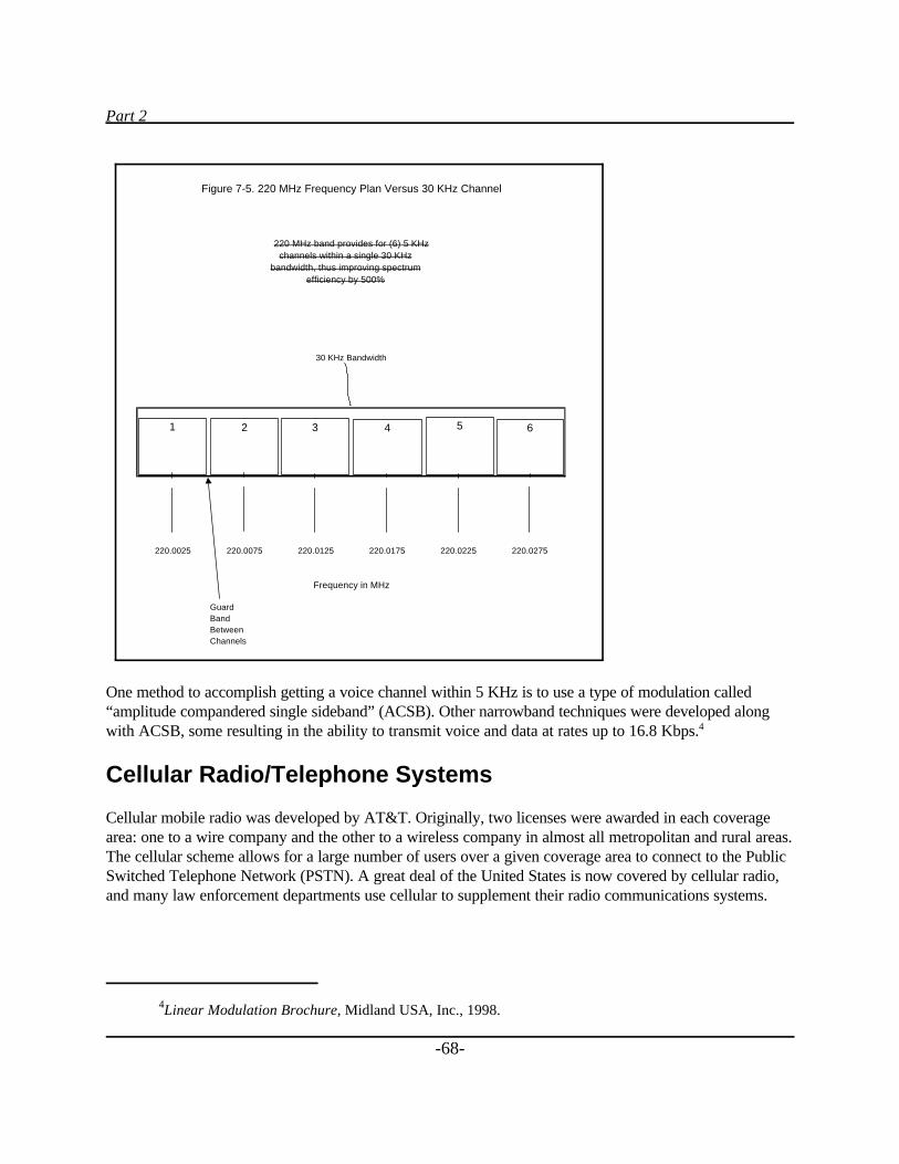
Part 2
4Linear Modulation Brochure, Midland USA, Inc., 1998.
-68-
One method to accomplish getting a voice channel within 5 KHz is to use a type of modulation called“amplitude compandered single sideband” (ACSB). Other narrowband techniques were developed alongwith ACSB, some resulting in the ability to transmit voice and data at rates up to 16.8 Kbps.4
Cellular Radio/Telephone Systems
Cellular mobile radio was developed by AT&T. Originally, two licenses were awarded in each coveragearea: one to a wire company and the other to a wireless company in almost all metropolitan and rural areas.The cellular scheme allows for a large number of users over a given coverage area to connect to the PublicSwitched Telephone Network (PSTN). A great deal of the United States is now covered by cellular radio,and many law enforcement departments use cellular to supplement their radio communications systems.
Figure 7-5. 220 MHz Frequency Plan Versus 30 KHz Channel
220 MHz band provides for (6) 5 KHzchannels within a single 30 KHz
bandwidth, thus improving spectrumefficiency by 500%
30 KHz Bandwidth
220.0025 220.0075 220.0125 220.0175 220.0225 220.0275
Frequency in MHz
GuardBandBetweenChannels
1 2 3 4 5 6
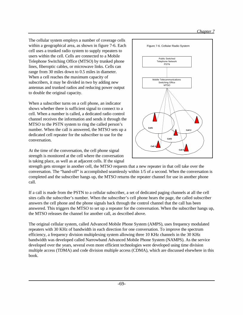
Chapter 7
-69-
The cellular system employs a number of coverage cellswithin a geographical area, as shown in figure 7-6. Eachcell uses a trunked radio system to supply repeaters tousers within the cell. Cells are connected to a MobileTelephone Switching Office (MTSO) by trunked phonelines, fiberoptic cables, or microwave links. Cells canrange from 30 miles down to 0.5 miles in diameter.When a cell reaches the maximum capacity ofsubscribers, it may be divided in two by adding newantennas and trunked radios and reducing power outputto double the original capacity.
When a subscriber turns on a cell phone, an indicatorshows whether there is sufficient signal to connect to acell. When a number is called, a dedicated radio controlchannel receives the information and sends it through theMTSO to the PSTN system to ring the called person’snumber. When the call is answered, the MTSO sets up adedicated cell repeater for the subscriber to use for theconversation.
At the time of the conversation, the cell phone signalstrength is monitored at the cell where the conversationis taking place, as well as at adjacent cells. If the signalstrength gets stronger in another cell, the MTSO requests that a new repeater in that cell take over theconversation. The “hand-off” is accomplished seamlessly within 1/5 of a second. When the conversation iscompleted and the subscriber hangs up, the MTSO returns the repeater channel for use in another phonecall.
If a call is made from the PSTN to a cellular subscriber, a set of dedicated paging channels at all the cellsites calls the subscriber’s number. When the subscriber’s cell phone hears the page, the called subscriberanswers the cell phone and the phone signals back through the control channel that the call has beenanswered. This triggers the MTSO to set up a repeater for the conversation. When the subscriber hangs up,the MTSO releases the channel for another call, as described above.
The original cellular system, called Advanced Mobile Phone System (AMPS), uses frequency modulatedrepeaters with 30 KHz of bandwidth in each direction for one conversation. To improve the spectrumefficiency, a frequency division multiplexing system allowing three 10 KHz channels in the 30 KHzbandwidth was developed called Narrowband Advanced Mobile Phone System (NAMPS). As the servicedeveloped over the years, several even more efficient technologies were developed using time divisionmultiple access (TDMA) and code division multiple access (CDMA), which are discussed elsewhere in thisbook.
Figure 7-6. Cellular Radio System
Public SwitchedTelephone Network
PSTN
Mobile TelecommunicationsSwitching Office
MTSO
Cell 5
Cell 4
Cell3
Cell 2 Cell1
Part 2
5 FCC Rules and Regulations, Section 24.129, Frequencies.
-70-
Strengths of the cellular system are:
1. A very large number of subscribers can be accommodated.
2. As the subscriber numbers in a cell reach the cell capacity, the cell may be divided to double itscapacity.
3. By keeping the transmitter power low in each cell, transmitting frequencies may be repeated innearby cells, thus increasing spectrum efficiency.
4. Cellular radio systems tend to be highly reliable even under the worst environmental conditions.
One weakness is that, with several different modulation schemes now being used, every cell phone does notwork in every system. Multimode phones have been developed to solve this problem.
Personal Communications Systems (PCS)
Because of the need for more frequencies for personal communications and the popularity and demand forcellular radio, the FCC reallocated several megahertz of frequencies in the 900 MHz range and a largeportion of the 2 GHz band for PCS. These frequencies were auctioned off to the highest bidder by the FCC.
The 900 MHz spectrum is allocated into 50 KHz channels, some paired with other 50 KHz channels andsome with 12.5 KHz channels.5 These are being used for two-way paging, data transmission systems forcarrying stock market and other information, and other uses conceived by the auction winners.
The 2 GHz band was auctioned off in much larger bandwidth segments, up to 30 MHz. (A small portion ofthe band was allocated for unlicensed operation to operate wireless PBX’s and other in-building voice anddata communications networks.) The broadband spectrum contains very few technical limitations forservice offerings so that companies with unique communications schemes might make creative use of thespectrum. However, so far, most offerings made public appear to be for additional cellular radio systems.
Buildouts are proceeding initially in high-density population areas where licensees can get a quick payback,so many rural areas may have to wait for service. Because of the number of winners in various areas, theremay be as many as six competitors in the densely populated areas.
Some seven different de facto technical approaches to these new cellular radio systems exist, so a telephoneused in one system will not necessarily work with another. Some confusion also exists between the 800MHz cellular services and the 2 GHz PCS cellular services because of advertising claims. Today,technologies used for cellular and PCS are basically the same and the offerings are very similar. However,PCS has the potential to provide other services in addition to cellular. People must wait and see as thetechnologies mature.
Chapter 7
-71-
Cellular Digital Packet Data
Cellular Digital Packet Data, or as it’s more commonly called, CDPD, consists of using cellular radiorepeaters for the transmission of small bursts of data known as packets. The CDPD process allows theinsertion of packets of data in between lightly modulated cellular radio voice channels without reducing cellphone voice capabilities. CDPD is an open transmission methodology for sending data on existingAdvanced Mobile Phone Service (AMPS) cellular networks at a transmission rate of 19.2 kilobits persecond. The need for sending digital packet data has increased over the years, so dedicated CDPD channelshave been set up by some of the cellular providers.
Law enforcement agencies have found that using laptop computers to obtain critical information in patrol cars without having to go through radio dispatchers improves their officers’ efficiency, decreases theinformation delivery time, and reduces errors. Using CDPD to bypass a dispatcher, field officers mayobtain information directly from NCIC to check driver’s license validity, existing warrants, and otherinformation that may be of use to an officer in processing a suspect.
The option of using CDPD minimizes the capital outlay by a public safety agency, since it is onlynecessary to purchase the in-vehicle equipment (e.g., laptop computers with modems and software) ratherthan purchasing the entire radio communications network for data transmission support.
Public safety agencies wanting to use CDPD should check with cellular service providers in their region tosee if they offer CDPD. Then they need to carefully check coverage to make sure that their operating areais adequately covered. Most cellular radio suppliers provide coverage diagrams for subscribers, and manyare available instantly over the Internet.
CDPD pricing is traditionally based on the number of bits transmitted, which is difficult to estimate forbudgeting. Recognizing the fixed budget nature of public safety departments, one vendor has startedoffering fixed monthly fee contracts, but so far no other companies have followed that vendor’s lead.
The network architecture uses the protocol used in the Internet (i.e., Transmission Control Protocol/Internet Protocol, or TCP/IP). Therefore, any standard personal computer modem that works with theInternet will operate with a CDPD system; however, special software must be used.
Point-To-Point Microwave Communications Systems
Often you need to connect telephone circuits from one terminal to another, voice and control circuits torepeaters and trunked systems, voting receiver inputs from satellite sites to a comparator, T1 (1.5 Mbps) orT3 (45 Mbps) data circuits, and other communications circuits from one point to another point. Generally,these needs may be fulfilled economically and reliably by leasing wire or fiber-optic circuits from the localtelephone or cable company.
When a telephone company expands capacity, it usually overbuilds to allow for future customers. If thecircuits exist, leasing payments involve only operational and maintenance costs. However, if the circuits donot exist, you must pay the up-front capital costs involved in constructing the new facilities.
Part 2
-72-
The economies of building a private microwave system usually are in your favor when it is necessary toprovide service to an area that would require new facility construction by the telephone company.
The microwave bands include frequencies generally above 960 MHz, or approximately 1 GHz. (Frequencybands used for commercial purposes are in the 960 MHz and 2, 4, 6, 11, 18, and 23 GHz areas.) The 960MHz band can be used to transmit up to 15 narrowband voice or data channels; the other frequency bandshave considerably wider bandwidths to accommodate many more voice and data channels. Microwavesystems may be either analog or digital radio systems.
Microwave propagation is considered “line of sight” (LOS), so transmissions must be repeated atapproximately 25-mile increments in bands up to12 GHz. In mountain areas, the spacing may be as greatas 60 miles. Above 10 GHz, rain attenuation usually causes a distance limitation, so repeaters must bemore closely spaced depending upon the amount of rain in different parts of the country.
Licensing
Most microwave systems require FCC licensing under part 101 of the Rules and Regulations. Frequencycoordination is required, and FCC Application Form 415 must be filled out. The Commission isexperimenting with a Universal Licensing System (ULS) using FCC Form 601, which will be implementedduring the year 2000. There is a class of microwave systems not requiring licensing by the Commissionunder part 15 of the Rules. Most unlicensed systems use spread spectrum modulation, which spreads thepower level over a large bandwidth.
-73-
PART 3
WIRELESS COMMUNICATIONS ISSUES
This portion of the handbook is a brief description of frequency licensing and pertinent FCC Rules, adescription of the newly reallocated television channel frequencies for public safety, a discussion of theFCC’s “refarming” policy, a discussion of FCC radiation specifications (OET Bulletin 65), andinformation on the FBI NCIC 2000 initiative. A brief discussion of future trends, including sharing ofspectrum resources between Federal and State/local agencies, also is included.
Chapter 8
-75-
Chapter 8_____
FCC Licensing, Rules, Regulations, and RelatedIssues
The FCC Rules and Regulations are printed in the Code of Federal Regulations (CFR), Title 47. Copies ofthe rules may be purchased from the Government Printing Office (GPO) (see resources in appendix D).The following parts of CFR 47 are of interest for mobile radio communications services:
Part 90 - Private Land Mobile Radio Services (PLMRS).Part 22 - Public Mobile Services. Part 24 - Personal Communications Services (PCS).Part 101 - Fixed Microwave Services.
Copies of the Rules may be downloaded from the FCC Web site (see resources in appendix D) orpurchased at GPO bookstores.
Licensing
If you are buying a system or constructing it yourself, you will need to apply for a license. However, beforeapplying to the FCC, you must obtain specific frequencies of operation from a frequency coordinator. Thecoordinator will check to see if any frequencies are available in your area and assist you in evaluating youroptions.
There are four coordinating bodies responsible for public safety-related frequencies:
APCO - Association of Public-Safety Communications Officials.IMSA - International Municipal Signal Association.FCCA - Forestry Conservation Communication Association.AASHTO - American Association of State Highway Transportation Officials.
In the past, the coordinator for most local public safety frequencies has been APCO. However, with theimplementation of refarming (see the end of this chapter), applicants may use the services of any frequencycoordinator certified to coordinate frequencies in its pool of eligibility. Contact numbers for all fourcoordinating bodies are given in resources, appendix D.
Part 3
-76-
The application form for radio licenses is FCC Form 600 for two-way radio frequencies (soon to bereplaced by FCC Form 601). For FCC microwave frequencies, the application is FCC Form 415. Formsare available from the FCC or may be downloaded from its Web site.
In addition, if one of your base, repeater, or microwave stations requires a tower or an antenna tip with aheight of 200 feet or more, you will need to complete a Federal Aviation Administration (FAA) Form 7460-1. If your antenna is within 5 miles of an airport runway and its height (in feet) is greater than or equal to40 times the distance to the runway (in miles), you will also need to complete the same form.
If you are purchasing communications services from a licensed vendor, you will not have to obtainlicensing. If you are sharing a system with another agency, make sure that the other agency is licensed.Normally, a letter contract or a memorandum of understanding (MOU) is drawn up between the licensedagency and a user.
FCC Rules and Regulations
Part 90
Part 90 covers the Rules for a number of private land mobile radio services including those for publicsafety. This section specifies the frequencies available for the various private and public safety services,licensing information, and technical and operating requirements. Technical rules include types ofmodulation, bandwidths, interference criteria, power output, and antenna height data.
Licenses require frequency coordination. Public safety agencies generally must use APCO for coordination.No Federal fees are required for license applications from local government applicants.
Docket 92-235. In FCC Docket 92-235, adopted in February 1997, the FCC reduced the number of servicepools for frequencies below 512 MHz to two:
1. Public safety, consisting of local government, police, fire, highway maintenance, forestryconservation, emergency medical, and special emergency.
2. Industrial/business, consisting of power, petroleum, forest products, film and video production,relay press, special industrial, business, manufacturers, telephone maintenance, motor carrier,railroad, taxicab, and automobile emergency.
Certified frequency coordinators for the particular services are still required to assign frequencies for theseservices. The FCC also authorized centralized trunking at allocated frequencies from 150 to 512 MHz,providing no harmful interference is caused to existing channels.
Part 22
Part 22 of the Rules covers the licensing and technical requirements for common carrier mobile radioservices, including paging and radio telephone services, rural radio telephone service, and cellular radio.
Chapter 8
6 “FCC Allocates More Spectrum to Public Safety,” Government Technology (March 1998): 12.
-77-
Public safety agencies may use these services as subscribers only; the licenses are held by the serviceproviders.
Part 24
Part 24 covers the Rules for personal communications services. This unique set of Rules deals with theauctioning of frequencies in the 900 MHz and 2 GHz bands. There is little technical detail, since winners ofthe auctions may provide many different types of service within the areas where they have won licenses.
At this time, the majority of 2 GHz PCS licensees are providing cellular voice services similar to those inthe cellular radio frequency band.
Part 101
Part 101 covers microwave point-to-point radio frequencies. Frequency coordination, licensing, andtechnical standards are identified.
Frequency Reallocation
A study was made by the public safety community, which declared its current need for additional spectrumdue to crowding and interference, as well as identified future requirements for interoperability andbroadband initiatives. As a result, the FCC, in December 1997, reallocated television channels 63 and 64(764-776 MHz) and 68 and 69 (794-806 MHz) for public safety communications (Docket 96-86). The neteffect will be to double the amount of spectrum available for public safety communications (figure 8-1).6
Frequency plans and the implementation schedule are being worked on by the FCC at this time.
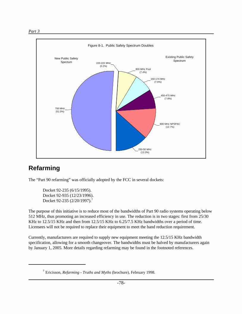
Part 3
7 Ericisson, Refarming - Truths and Myths (brochure), February 1998.
-78-
Refarming
The “Part 90 refarming” was officially adopted by the FCC in several dockets:
Docket 92-235 (6/15/1995). Docket 92-935 (12/23/1996).Docket 92-235 (2/20/1997).7
The purpose of this initiative is to reduce most of the bandwidths of Part 90 radio systems operating below512 MHz, thus promoting an increased efficiency in use. The reduction is in two stages: first from 25/30KHz to 12.5/15 KHz and then from 12.5/15 KHz to 6.25/7.5 KHz bandwidths over a period of time.Licensees will not be required to replace their equipment to meet the band reduction requirement.
Currently, manufacturers are required to supply new equipment meeting the 12.5/15 KHz bandwidthspecification, allowing for a smooth changeover. The bandwidths must be halved by manufacturers againby January 1, 2005. More details regarding refarming may be found in the footnoted references.
Figure 8-1. Public Safety Spectrum Doubles
150-174 MHz(7.6%)
450-470 MHz(7.8%)
800 MHz NPSPAC(12.7%)
700 MHz(51.0%)
800 MHz Pool(7.4%)
220-222 MHz(0.2%)
250-50 MHz(13.3%)
New Public SafetySpectum
Existing Public SafetySpectrum
Chapter 9
-79-
Chapter 9_____
Radiofrequency Electromagnetic RadiationExposure
The FCC Office of Engineering and Technology (OET) Bulletin 65, Evaluating Compliance with FCCGuidelines for Human Exposure to Radiofrequency Electromagnetic Fields was upgraded in August 1997to ensure the protection of human beings working around or near radio-transmitting facilities. Thecompliance is divided into two parts—one for “occupational or controlled exposure” and one for the“general population or uncontrolled exposure.” OET Bulletin 65 is available for downloading atwww.fcc.gov/oet/rfsafety. All existing transmitting facilities and operations must be in compliance with theregulations by September 1, 2000.
Table 9-1 shows a chart with the maximum permissible exposures in each category. The basis for the chartis the thermal effect of radio frequency (RF) energy on human tissue. The worst frequency for RFabsorption is in the 100 to 300 MHz range. At that frequency, the highest RF level in controlled areas is 1mW/cm2 for 6 minutes of exposure time and 200µW/cm2 in uncontrolled areas for 30 minutes of exposuretime.
Calculations are explained and examples are given in the OET Bulletin. At the time of initial licenseapplications and renewals, a licensee must certify that these conditions will be met. This may require thattransmitter output powers be reduced or that transmitters be turned off while technicians work neartransmitters or climb towers.
At multiple transmitter sites, the contributions of each system must be calculated and then are addedtogether to determine if the site meets compliance. At sites where there are many transmitters and antennasover large frequency ranges, calculations may become too difficult to perform accurately, and actualmeasurements may have to be made.
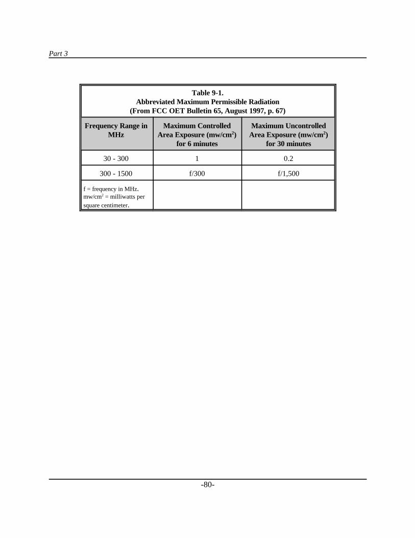
Part 3
-80-
Table 9-1.Abbreviated Maximum Permissible Radiation
(From FCC OET Bulletin 65, August 1997, p. 67)
Frequency Range inMHz
Maximum ControlledArea Exposure (mw/cm2)
for 6 minutes
Maximum UncontrolledArea Exposure (mw/cm2)
for 30 minutes
30 - 300 1 0.2
300 - 1500 f/300 f/1,500
f = frequency in MHz.mw/cm2 = milliwatts persquare centimeter.
Chapter 10
8 “FBI Readies New Crime Information Network,” Government Technology Reseller (March 1998): 30.
9 Ibid.
-81-
Chapter 10_____
FBI NCIC 2000
The FBI’s National Crime Information Center (NCIC) computer provides all 50 States with access to therecords in the databases. Currently, more than half a million users in some 80,000 agencies make 1.7million inquiries per day to NCIC.8 Harris Corporation has been awarded a contract to upgrade the NCICsystem, which includes replacement of the old computers with new IBM® 390 mainframes and operatingsystems. Projections call for up to 2 million transactions per day.
The NCIC 2000 project expects to support communication with mobile-imaging units in patrol cars.9 Theupgraded system will require that communicating units use TCP/IP over X.25 protocol before the system isplaced online. After many users’ requests, the FBI is considering other protocols such as TCP/IP overpoint-to-point protocol (PPP), Ethernet, and additional options. The FBI has conducted tests using variouscommunications technologies, including CDPD, 800 MHz alone, and 800 MHz in conjunction withmicrowave.
An NCIC 2000 workstation has been developed for mobile-imaging units to transmit and receive mug shotsand fingerprints. Plans call for high-quality imaging, including mug shot field imaging with high- qualityfield cameras so that officers may simply point and click. A quick check of a right index fingerprint will bepossible with the fingerprint-matching subunit planned for use in the system. When the system is completeand operational, a field officer will be able to:
$ Enter a wanted person’s fingerprint, mug shot, and identifying images.$ Identify a wanted person using a fingerprint.$ Modify a fingerprint entered into NCIC 2000 with a new fingerprint.$ Link a wanted person’s fingerprint to one entered by another organization.$ Cancel a wanted person’s fingerprint.$ Receive ownership of a linked fingerprint when the original owner canceled the entry.
Part 3
-82-
The NCIC workstation and the MIU (mobile imaging unit) will be based on Intel’s Pentium technology.The most recently published (April-May 1998) minimum specifications for NCIC 2000 workstationsrequired the following:
$ Pentium processor.
$ 16 MB memory.
$ Storage capacity in the gigabyte range (minimum of 120 MB for the NCIC 2000 applications).
$ RS232 serial port (based on the 16550 Universal Receiver/Transmitter [UART] chip forcommunications with the MIU).
$ Monitor capable of displaying 1024 x 768 pixels and 64 gray shades with a Windows® driver andvideo card.
$ Two-button mouse (Microsoft® compatible).
$ Extended 101-key keyboard.
$ 3.5-inch floppy disk drive (CD-ROM drive also recommended).
$ Adaptec® SCSI board or comparable.
$ One ISA slot for a communications board (EICON® X.25 configured under TCP/IP).
In addition to the above specifications, the FBI has published requirements for peripheral equipment(printers, scanners, dataradio modems, etc.), commercial off-the-shelf software (COTS), and NCIC 2000workstation applications software (to be provided by the FBI to the States at no cost).
All of these specifications, as well as the latest status on the testing and implementation of the NCIC 2000project, may be found at the FBI Web site or by contacting the FBI directly (see resources in appendix D).
-83-
PART 4
WIRELESS COMMUNICATIONS OPTIONS
This section looks at the options public safety agencies have for wireless communications, including thepurchase of their own radio components and systems. The authors also have included examples in whichlocal governments have used commercial services.
One special case is described in which a tower and radio supplier provided radio communications to a townby entering into an agreement to use some of the town’s high-elevation real estate for commercial radiodevelopment in return for dedicated government radio systems.
Examined are the many commercial voice and data services available to law enforcement, including cellularand PCS, CDPD, SMR/ESMR, and data networks.
Networks are complicated. They consist of three generic components—hardware, software, andmiddleware. Hardware consists of radios, modems, and laptop computers; software is the programmingthat runs the radio controllers, modems, and laptop computers; and middleware is the (software) glue thatinterconnects all the components together. Middleware must be selected that supports the requiredhardware and software protocols.
A reminder: All radio systems should be carefully checked to make sure they have the coverage you need. Ifyou are purchasing a new system, make sure that the supplier gives you written assurances that the systemmeets your needs. If you need to communicate with handheld radios in reinforced concrete buildings, makesure the supplier knows and makes calculations taking that into account. There are independent consultantswho also can perform these calculations if you need a verification check. If the radio network is alreadyconstructed, borrow or rent equipment from the supplier and make sure the coverage satisfies yourrequirements.
Chapter 11
-85-
Chapter 11_____
Voice Systems
Dedicated Radio Systems
Dedicated public safety radio systems include all radio technologies, ranging from conventional FMsimplex and repeater systems to very complex and expensive trunked wide-area analog and digital radiosystems at all of the two-way frequencies.
There are many suppliers for public safety radio systems. Three companies, however, have supplied andcontinue to supply the majority of public safety radio systems: Motorola, ComNet Ericsson, and the E.F.Johnson division of Transcrypt.
The three major companies had representatives on the Project 25 Committee, which selected the first phasedigital trunked system technology standard to carry public safety communications into the next century.The Motorola protocol was selected for the first phase, and Motorola has offered its intellectual properties,royalty free, to other suppliers to allow competition. A large number of suppliers are developing systemsusing the new standard.
There are many other smaller suppliers of FM equipment, and some are supplying narrow band systems forthe 220 MHz frequency band.
Sample Vendors
Motorola, Inc. Motorola offers some very sophisticated digital radio networks, as evidenced by itsSmartZone® system, which can be configured for conventional repeaters, single or multiple site trunkedrepeaters, and/or simulcast trunked repeaters, as shown in figure 11-1. The company is currently upgradingthe radio and dispatch systems for the city of Los Angeles.
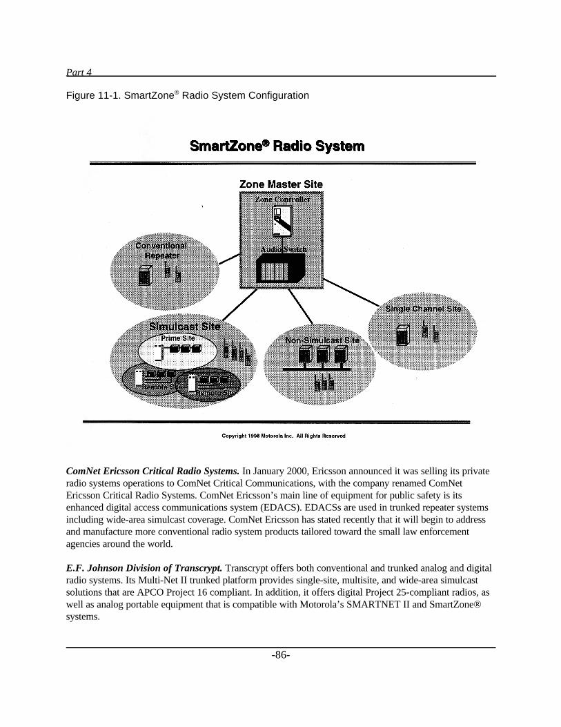
Part 4
-86-
Figure 11-1. SmartZone® Radio System Configuration
ComNet Ericsson Critical Radio Systems. In January 2000, Ericsson announced it was selling its privateradio systems operations to ComNet Critical Communications, with the company renamed ComNetEricsson Critical Radio Systems. ComNet Ericsson’s main line of equipment for public safety is itsenhanced digital access communications system (EDACS). EDACSs are used in trunked repeater systemsincluding wide-area simulcast coverage. ComNet Ericsson has stated recently that it will begin to addressand manufacture more conventional radio system products tailored toward the small law enforcementagencies around the world.
E.F. Johnson Division of Transcrypt. Transcrypt offers both conventional and trunked analog and digitalradio systems. Its Multi-Net II trunked platform provides single-site, multisite, and wide-area simulcastsolutions that are APCO Project 16 compliant. In addition, it offers digital Project 25-compliant radios, aswell as analog portable equipment that is compatible with Motorola’s SMARTNET II and SmartZone®systems.
Chapter 11
-87-
Advantages of Dedicated Systems
1. Public safety entities may generate specifications to meet their exact system needs. They have completecontrol of the design and operations.
2. As part of the tailoring, the priority of use may be established within the entity.
3. Combined dedicated radio systems (i.e., shared with other communities) may save considerableinvestment and still preserve the tailoring at a more reasonable cost per agency.
Disadvantages of Dedicated Systems
1. The capital outlay may be quite high and prohibitive for a small to medium-size community.
2. The owner of the system must pay for all maintenance and improvements.
Cellular and PCS Radio
Many law enforcement agencies are already using cellular radio systems in addition to their dedicated radiosystems for the transmission of voice messages. Almost all urban and suburban areas in the United Statesare covered by one or more cellular providers, although in sparsely populated areas, coverage may not beavailable.
In addition, the construction of personal communications systems (PCS), most of which are cellularsystems in the 2 GHz band, has proliferated in higher density areas, and these systems are competingdirectly with 800 MHz cellular communications systems. There are as many as nine different technologiesbeing used by different suppliers of cellular and PCS radio, so, once a user has chosen a company andhandsets, it may be stuck with that supplier until the end of the contract.
System Coverage
System coverage is a major consideration in selecting a cellular system or PCS. The first thing to do whenyou think you want cellular or PCS service is identify the suppliers in your area. Contact them or go to theInternet and obtain a coverage map for your area for each supplier aswell as its prices and terms. Borrow phones from suppliers and testdifferent systems, where available, to determine which one covers yourneeds best.
Pricing
With the advent of increasing competition in many areas of the UnitedStates, the pricing packages are changing rapidly, so you will need to getthe latest information at the time of purchase. Law enforcement may have
L Try this...
Identify wirelesscarriers in your areaat CTIA’s Web site:
http://www.wow-com.com
Part 4
-88-
an advantage in negotiating with suppliers since it is a highly visible public agency.
Sample Vendors
AT&T Wireless Services. AT&T has cellular and PCS licenses for most of the States in the country.However, they are not licensed in Montana, North Dakota, parts of Minnesota, Wyoming, or Texas. Todetermine if they provide coverage in your area, it is best to get the actual current coverage maps showingthe specific area of interest. (Most can be obtained from the AT&T Wireless Services Web site,http://www.attws.com.)
Sprint®. Similarly, Sprint has almost all the Nation licensed for PCS coverage, but it is building itsnetwork in the highest density areas first, where it can most easily attract a large number of subscribers.
Advantages of Cellular/PCS Radio
1. Where there is coverage, subscribers should be able to contact any field or fixed personnel, regardless ofagency or jurisdiction (i.e., supports a high level of interoperability).
2. Pricing is competitive in most areas.
3. Service can supplement dedicated radio communications.
4. With digital protocols used by many cellular/PCS radios, listening by unauthorized scanners is limited oreliminated.
5. Under certain emergency conditions, some vendors can supply portable cell sites to the scene to providefor increased cellular radio traffic.
Disadvantages of Cellular/PCS Radio
1. Coverage is limited or nonexistent in sparsely populated areas.
2. Most systems competing in local areas use different modulation techniques so that a particular handheldphone may not work with any other system.
3. In some locations, cellular radio systems are prone to overload in emergency situations.
Chapter 11
-89-
Voice—SMR/ESMR
When the FCC wrote the trunked radio Rules, it provided for licensing specialized mobile (trunked) radioservice companies (SMRs) to provide leased two-way mobile radio service. As time passed, with thedevelopment of digital radio trunking systems called “enhanced specialized mobile radio” (ESMR), greaterspectrum efficiency was achieved. These systems use the 800 and 900 MHz portions of the radio spectrum.
A Special Case:Conventional Radio System for the Township of Upper St. Clair, Pennsylvania
Upper St. Clair, a Pittsburgh suburb, has a unique problem of having deep narrow ravinesthroughout the township, making full radio coverage with its 460 MHz law enforcement systemimpossible. Patrol cars were unable to communicate with headquarters on roads at the bottom ofsome of these ravines. Also, the radios were installed years before, required excessive servicing, andwere overdue for replacement.
The town did have one asset. The town’s communications tower was in a high city park, overlookingmuch of Pittsburgh, making it an attractive site for other radio systems. The township wasapproached by Crown Communications, a commercial radio enterprise, to enter into a contract toinstall a new radio system and tower for the town’s law enforcement communications, providingCrown could use the tower for commercial communications.
Crown used a computer propagation model to predict that, by replacing the present police system,with its antenna at 180 feet above the ground, with a new antenna with a down-tilt radiation patternat 350 feet above the ground at the same location, a 460 MHz communications system would havepractically full township coverage.
St. Clair officials recognized a good offer when they saw one. At no cost, Crown provided St. Clairwith a new 350-foot tower (with police repeater antenna and room for expansion), a new basestation, new mobile units, and new handheld radios. In addition, St. Clair got a zero-cost radio unitmaintenance plan, as well as a small monthly lease income for making the site available and forallowing the company to construct a communications facilities building and install a number ofcommercial systems.
In a single “win-win” contract, St. Clair solved both its obsolete equipment problem (at no cost) andits coverage problem (tests showed the new system had excellent coverage, even at the bottom of theravines).
Although deals as sweet as St. Clair’s may not come along every day, your community may haveassets that could lead to a similar “horse-trade” for equipment or commercial services.
Part 4
10 “Nextel Benefit” sheet, supplied by Nextel in April 1998, private communications from Robert Kuck,
Major Account Executive.
11 Nextel, Overview of iDEN, R01.04.02, April 24, 1997, p. 3.
-90-
Many SMR/ESMR systems are extremely reliable and are well suited for use by public safety agencies.SMR/ESMR systems work well for radio dispatch and for interconnection to the public telephone system.Offerings are usually competitive with other available mobile radio services.
Sample Vendor—Nextel
One ESMR provider with national coverage is Nextel (although, like the cellular/PCS providers, itspresence is spotty in small-population areas). Nextel’s system uses Motorola’s iDEN equipment.
The system is quite similar to that of cellular radio; however, in addition to making phone calls, Nexteloffers paging and dispatching services whereby a subscriber may call another mobile station or a group ofstations on company-owned repeaters. The service allows for full duplex communications. Thus, one devicegives you the capabilities of both a cellular phone and a handheld radio.
Services. Some of the specific Nextel services that may be of interest to law enforcement agencies are:10
1. Dispatcher to a single mobile station voice communications.
2. Dispatcher to a group of mobile communications.
3. Fast delivery paging and messaging so that a police officer may receive an alphanumeric message within30 seconds and be able to acknowledge receipt. Using this kind of messaging may provide a minimumnumber of interruptions for officers on a beat.
4. Mobile-to-mobile private communications.
5. Mobile-to-PSTN telephone system for local and long-distance telephone calls.
6. Talk groups may be customized and private conferences arranged. A SWAT group may take advantageof this kind of communications.
7. Customized billing allows administrators to see exactly who is using the system, so they may controlcosts.
Nextel has several models of handsets, and you must use one made by the company.
Five types of dispatch calls may be made with Nextel’s system: private calls, call alerts, local service areagroup calls, selected service area group calls, and wide-area group calls.11
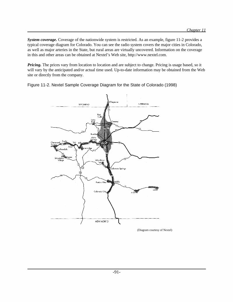
Chapter 11
-91-
System coverage. Coverage of the nationwide system is restricted. As an example, figure 11-2 provides atypical coverage diagram for Colorado. You can see the radio system covers the major cities in Colorado,as well as major arteries in the State, but rural areas are virtually uncovered. Information on the coveragein this and other areas can be obtained at Nextel’s Web site, http://www.nextel.com.
Pricing. The prices vary from location to location and are subject to change. Pricing is usage based, so itwill vary by the anticipated and/or actual time used. Up-to-date information may be obtained from the Website or directly from the company.
Figure 11-2. Nextel Sample Coverage Diagram for the State of Colorado (1998)
(Diagram courtesy of Nextel)
Part 4
-92-
Sample Vendor—Lower Colorado River Authority
The Lower Colorado River Authority (LCRA) is a conservation and reclamation district in Texas thatmonitors and controls portions of the Colorado River. LCRA has a very extensive ComNet EricssonEDACS digital radio system with extra capacity available for leasing to other utilities and, most recently,to public safety organizations.
When the San Marcos, Texas, Police Department’s proposal for a $3.5 million upgrade for its radio systemwas rejected by the city council, the department needed to find a less costly alternative. LCRA provided aconvenient option. The Authority supplied a new communications tower and a seven-channel trunked(EDACS) 900 MHz radio system within San Marcos. The city council approved $700,000 for the purchaseof about 300 new mobile and portable radios, plus four new dispatch consoles. It also arranged for theinstallation of a T1 circuit to link the city communications center to the trunked repeaters.
San Marcos currently uses the radio system for voice transmissions. However, it will be installing laptopcomputers in squad cars in the near future. The city is evaluating new software for the dispatch center,which will allow laptops to communicate directly with NCIC.
San Marcos is paying LCRA a flat channel fee of $19.95 per month per mobile unit and $9.99 per monthfor each portable. LCRA takes care of all maintenance at its trunked facility.
Although LCRA will not prioritize public safety traffic along the network, when the first San Marcosemergency (27 inches of rain fell in October 1998) pushed the number of radio transmissions up from anormal average of 16,000 per day to 41,000 per day, the system operated well, with only a few minorhitches.
Advantages of an SMR/ESMR System
1. Capital expenses are amortized in monthly invoices and spread over the total customer base of thecompany.
2. Many modes of operation are available by using this service, as discussed above.
Disadvantages of an SMR/ESMR System
1. The agency must purchase special telephone/radio units.
2. Prioritizing transmissions for public safety agencies is generally not provided at this time. In case of anemergency, public safety agencies may not be preferred customers.
3. Flat rate billing may not be provided. Rates are commonly based upon a fixed fee plus usage.
4. The service may not be available in your area.
Chapter 12
-93-
Chapter 12_____
Wireless Data Systems
Data transmission requirements of local public safety agencies continue to increase as computer-to-computer communications needs spread. Today, agencies need rapid radio access to governmentaldatabases to obtain relevant information about vehicles, drivers, histories, hazardous material storageareas, and so forth.
Laptop computers are becoming standard equipment in vehicles to allow for accurate and quick inquiries.These computers may be connected to almost any radio system, with the proper modem. Agencies haveused and continue to use dedicated, agency-owned radio systems for data, both conventional and trunked.However, increasingly commercial options have appeared in the marketplace. One such system (describedbelow), which has become more and more popular, is cellular digital packet data, with expanded offeringsin many parts of the country.
Regardless of the type of radio system used for data transmission, software also is required for thesesystems to work properly. Software on the laptop (usually licensed on a per-PC basis) and software back atthe main computer site must both be present and be able to talk to each other over whatever backbone youselect. The effective speed of your data network will depend heavily on the efficiency of the software usedto pass the data back and forth.
Cellular Digital Packet Data (CDPD)
If you are planning on transmitting data for dispatching, for license and criminal record information, or forwriting accident reports, CDPD may be the technology to use. CDPD uses packet radio hardware andsoftware and is regularly used with laptop computers or mobile data terminals. CDPD may be availablefrom a cellular supplier in your area. Some CDPD suppliers with interesting offerings are described in thefollowing section.
Sample Vendors
AT&T Wireless. AT&T Wireless Services developed a white paper in 1997 titled “CDPD for PublicSafety,” outlining the use of CDPD by law enforcement agencies. The document includes information onthe wireless environment applicable to public safety dispatch users and the economics for CDPD usage. Itcompares CDPD with the other options available to public safety organizations for the transmission of
Part 4
12 Vlcek, Charles, “CDPD for Public Safety,” AT&T White Paper, May 29, 1997.
13 Wireless Week (June 1, 1998): 28.
14 Radio Resource Magazine (June-July 1998): 46.
15 Ibid, p. 48.
-94-
wireless mobile data, including government-owned voice- and data-dedicated private mobile radio systems,specialized mobile radio (SMR) trunked radio systems, and public networks.12 Note that the document is amarketing piece and, thus, tends to downplay the disadvantages of CDPD, but not unfairly.
AT&T is offering CDPD service for public safety use on a fixed-price per vehicle per month schedule;other providers have not yet followed suit.
The McKinney Police Department (near Dallas, Texas) is using AT&T CDPD and claims to have savedclose to $500,000 by using AT&T’s wireless network. The department equipped its patrol cars withlaptops, modems, and other necessary equipment. The city is using the network to obtain history reports ondomestic violence and to perform criminal and vehicle checks.13
Bell Atlantic Mobile. Bell Atlantic Mobile offers their Airbridge® service using CDPD to access theInternet as well as corporate or local government internal computers for database inquiries.
The Metropolitan Police Department of Washington, D.C., uses Airbridge®, and patrol car personnelregularly access criminal databases and motor vehicle records using laptop computers.14
GTE Wireless. GTE offers an “Intelligent Patrol” turnkey package that bundles together hardware(including a ruggedized laptop computer and modem), software and service, training, installation,integration, and maintenance, with a leasing option.15 The laptop computer can handle inquiries to criminaldatabases, warrants, and mug shots. Besides retrieving information, laptops can also dispatch using CDPD.GTE offers usage-based pricing on its service.
Advantages of CDPD
1. The service is available in many areas in the United States and is ideal for applications involving shortrapid data exchange. Police officers can readily access local, State, and national databases from their patrolcars.
2. The capital expenses are only for computers, modems, and software. The communications network isprovided by the cellular service provider, so entry costs for agencies are quite low.
3. Information may be obtained quickly from database resources, including NCIC, without the need toextend time to go through a dispatcher.
Chapter 12
-95-
4. The accuracy of the information may be better if it is directly obtained from a law enforcement databasewithout any voice involved.
5. Industry standard TCP/IP protocols make the connection with standard databases.
6. Some service providers are willing to prioritize traffic on their CDPD networks so that law enforcementmay be able to displace noncritical traffic during emergencies.
7. Hardware and software are available from multiple sources, allowing for competitive bids in acommunity where there is more than one source.
8. CDPD can act as a backup communications network if the primary law enforcement radiocommunications network goes down.
Disadvantages of CDPD
1. CDPD cell coverage may be limited or not available in sparsely populated communities or rural areas.
2. There may not be enough capacity to handle law enforcement requirements during a heavy rush forinformation.
3. The maximum data rate is 19,200 bps, which may not be satisfactory for obtaining high-qualityfingerprints or complex mug shots quickly.
4. In large agencies with a large number of vehicles, the cumulative cost of CDPD service could exceed thecost of a dedicated radio infrastructure.
5. Some service providers will not prioritize traffic for public safety users.
Private National Data Networks
At this time, there are two private national data networks: ARDIS and RAM. Both networks offer datacommunications services within urban areas and between many cities across the continental United States,Alaska, and Hawaii.
Sample Vendors
Motient Wireless Data Network (founded as American Mobile Satellite Corporation). Motient completedits acquisition of the ARDIS mobile data network in March 1988. The company name was changed inApril 2000. Motient has an extensive data network in more than 500 U.S. cities (including cities in Alaska,Hawaii, Puerto Rico, and U.S. Virgin Islands), providing services for in-building, on-street, and in-vehiclelocations. Some 1,900 base stations are tied together to form a national backbone. PC, LAN, and
Part 4
16“RAM Mobile System Overview,” Executive Summary, August 1995.
-96-
mainframe systems can be connected to the Motient network via radio modems, dial-up, or dedicated leasedlines.
The company now claims to provide services to many rural areas (90 percent of the U.S. area containing80 percent of the population), much of which is not well covered by other wireless services. As a result,small public safety entities in remote areas may have a commercial option for obtaining databaseinformation from far-flung databases or for other computer or voice communications.
Packet data network technology is employed by the system. According to the company, the combinedsatellite/terrestrial network allows the company to optimize the transmission of data by using bothterrestrial and satellite paths, thus minimizing their costs.
Services provided by the company include:
1. Wide-area two-way voice and messaging services.2. Telephone interconnect.3. Digital voice dispatch.4. Data communications.5. Position reporting services. 6. Internet messaging.
The system can employ a number of different hardware configurations, including laptop and palmtopcomputers with appropriate wireless modems. The system is software and middleware driven. Compatiblesoftware and hardware are supplied by a number of vendors. Motient has nationwide contracts withorganizations such as AT&T, Pitney Bowes, IBM, Avis, Sears, and Otis Elevator Company.
BellSouth® Mobile Data (RAM Network). BellSouth Mobile Data Corporation took over RAM MobileData in early 1998 and is expanding the number of base stations in metropolitan areas across the UnitedStates. According to BellSouth, “the primary objective of the RAM network is to send and receivemessages and data from anywhere at anytime.”16
The system is a data-only, packet-switched network and uses packets of 512 bytes transmitted at an 8 Kbpsrate. Efficient addressing, automatic repeat requests, and forward error correction are used in the networkmaking it 99.99 percent reliable, according to the company.
The base stations use transmitters with 200 watts ERP, and mobiles transmit with up to 2 watts. Amultitude of trunked base stations are used throughout all the metropolitan areas in the United States. UHFSMR channels are used to transmit the data. The data are encrypted by scrambling the packets to provideprivacy to customers and may be further encrypted by customers, if required.
Chapter 12
17“MOBITEX Features and Services,” RAM Mobile Data White Paper, February 1997.
-97-
The service is based upon ComNet Ericsson’s Mobitex® standard used throughout Europe. The networksupports many data communications protocols including UDP/IP, TCP/IP, SNA/3270, X.25,asynchronous, and MPT/1 transport protocol.17
The network can perform the following tasks:
1. Transmit and receive messages and pages, including inquiries to databases. 2. Allow transmission of group messages.3. Respond within 6 to 10 seconds to the pages and messages as a positive acknowledgment.4. Send text-to-voice messages.5. Query Web sites.6. Send faxes.7. Send and receive e-mail.8. Connect to PSTN to dedicated lines or to the Internet.9. Store and forward messages for up to 72 hours.
To operate on the RAM network, an agency needs laptop or palmtop computers, application softwaresupported by appropriate middleware, a wireless modem, and BellSouth’s RAM wireless two-way datatransmission service. BellSouth provides open interfaces that enable many vendors to supply hardware,software, and system integration services.
Coverage information may be obtained from the company’s Web site. As said previously, an agency isencouraged to perform its own coverage testing before making a commitment for the use of the network.
Information on the system may be obtained by calling BellSouth or by visiting its Web site.
Advantages of Private National Data Networks
1. Network store and forward. Packets may be stored for sending at a later time.
2. Companies guarantee fast network response and delivery of data, within seconds of being transmitted.
3. Both companies provide encrypted service, if desired.
4. Costs are proportional to usage.
Disadvantages of Private National Data Networks
1. The two national data networks do not yet support data rates in excess of 8 kbps.
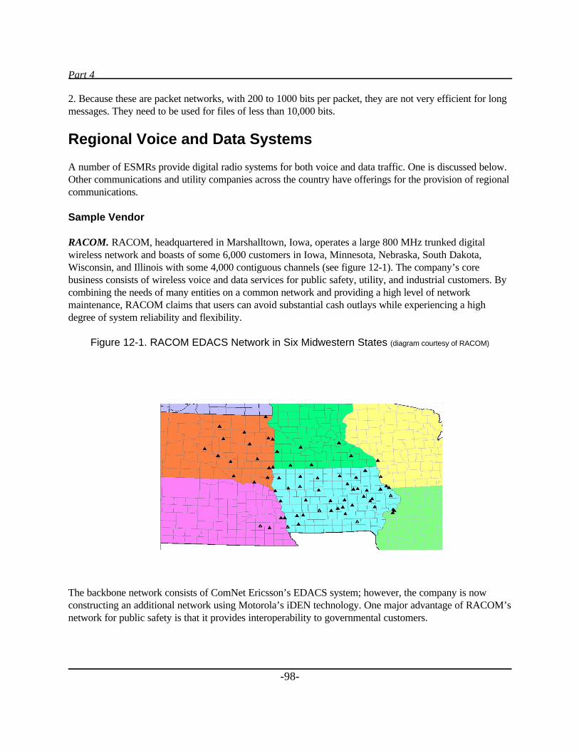
Part 4
-98-
2. Because these are packet networks, with 200 to 1000 bits per packet, they are not very efficient for longmessages. They need to be used for files of less than 10,000 bits.
Regional Voice and Data Systems
A number of ESMRs provide digital radio systems for both voice and data traffic. One is discussed below.Other communications and utility companies across the country have offerings for the provision of regionalcommunications.
Sample Vendor
RACOM. RACOM, headquartered in Marshalltown, Iowa, operates a large 800 MHz trunked digitalwireless network and boasts of some 6,000 customers in Iowa, Minnesota, Nebraska, South Dakota,Wisconsin, and Illinois with some 4,000 contiguous channels (see figure 12-1). The company’s corebusiness consists of wireless voice and data services for public safety, utility, and industrial customers. Bycombining the needs of many entities on a common network and providing a high level of networkmaintenance, RACOM claims that users can avoid substantial cash outlays while experiencing a highdegree of system reliability and flexibility.
Figure 12-1. RACOM EDACS Network in Six Midwestern States (diagram courtesy of RACOM)
The backbone network consists of ComNet Ericsson’s EDACS system; however, the company is nowconstructing an additional network using Motorola’s iDEN technology. One major advantage of RACOM’snetwork for public safety is that it provides interoperability to governmental customers.
Chapter 12
18SMR/Private Radio, “Agencies to Operate RACOM System,” Wireless Week (March 30, 1998).
19 Ibid.
-99-
For example, the cities of Moline and East Moline, Illinois, put out bid requests for dispatch centers andradio equipment for their police, fire, emergency medical, and public works departments. Two biddersresponded. One proposed two dispatch centers; the other, RACOM, proposed a combined center. TheRACOM proposal offered each department in each city separate frequencies for specific talk groups andoffered clear channels for intra-city communications when required.18 The cities went with the RACOMplan, thus saving the money to be spent on a second center.
RACOM provided the Fort Dodge (Iowa) Correction Facility with the capability for transmitting voice,data, dispatch, and vehicle-tracking signals. Of special concern was the plausibility of being able totransmit and receive signals within all areas of the prison. RACOM established a transmitting facilitywithin a half mile of the prison, and, as a result, there are no dead spots within the prison facility.19
Besides RACOM’s public safety customers mentioned above, as of 1999, the company serviced BlackHawk County, Iowa; Dubuque County, Iowa; Polk County, Iowa; Sioux City, Iowa; Lincoln, Nebraska;Milan, Illinois; Rock Island Arsenal, Illinois; Yankton, South Dakota; city of Waterloo, Iowa; and the U.S.Army Corps of Engineers. Additionally, RACOM has commercial customers including Deere & Co.,General Mills, Rockwell International, MidAmerican Energy, Utilicorp, and East River Electric.
Advantages of Regional Voice and Data Systems
1. Lower capital outlay by sharing existing system.
2. Maintenance is taken care of by the system supplier.
3. Capital expenses are amortized in monthly invoices and spread over the total customer base of thecompany.
4. Many modes of operation are available by using this service, as discussed previously.
Disadvantages of Regional Voice and Data Systems
1. Law enforcement agency does not have complete control over the system.
2. The agency must purchase special telephone/radio units.
3. Prioritizing transmissions for public safety is often not provided. In case of an emergency, public safetyagencies may not be preferred customers.

Part 4
-100-
4. Flat rate billing may not be provided by companies. Rates are commonly based upon a fixed fee plususage.
5. The service may not be available in your area.
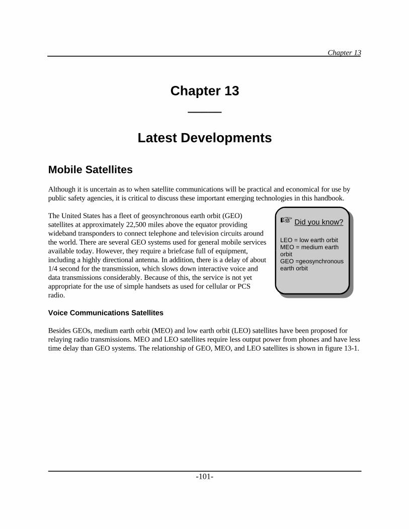
Chapter 13
-101-
Chapter 13_____
Latest Developments
Mobile Satellites
Although it is uncertain as to when satellite communications will be practical and economical for use bypublic safety agencies, it is critical to discuss these important emerging technologies in this handbook.
The United States has a fleet of geosynchronous earth orbit (GEO)satellites at approximately 22,500 miles above the equator providingwideband transponders to connect telephone and television circuits aroundthe world. There are several GEO systems used for general mobile servicesavailable today. However, they require a briefcase full of equipment,including a highly directional antenna. In addition, there is a delay of about1/4 second for the transmission, which slows down interactive voice anddata transmissions considerably. Because of this, the service is not yetappropriate for the use of simple handsets as used for cellular or PCSradio.
Voice Communications Satellites
Besides GEOs, medium earth orbit (MEO) and low earth orbit (LEO) satellites have been proposed forrelaying radio transmissions. MEO and LEO satellites require less output power from phones and have lesstime delay than GEO systems. The relationship of GEO, MEO, and LEO satellites is shown in figure 13-1.
L Did you know?
LEO = low earth orbitMEO = medium earthorbitGEO =geosynchronousearth orbit
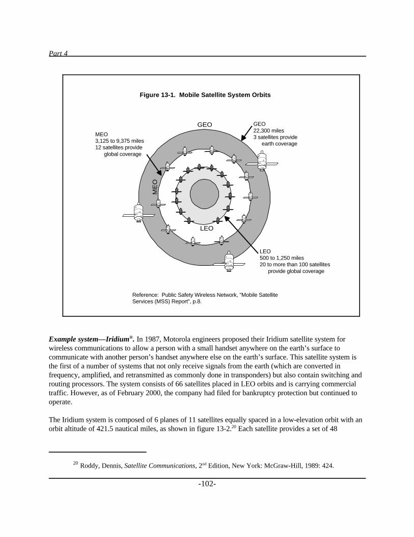
Part 4
20 Roddy, Dennis, Satellite Communications, 2nd Edition, New York: McGraw-Hill, 1989: 424.
-102-
Example system—Iridium®. In 1987, Motorola engineers proposed their Iridium satellite system forwireless communications to allow a person with a small handset anywhere on the earth’s surface tocommunicate with another person’s handset anywhere else on the earth’s surface. This satellite system isthe first of a number of systems that not only receive signals from the earth (which are converted infrequency, amplified, and retransmitted as commonly done in transponders) but also contain switching androuting processors. The system consists of 66 satellites placed in LEO orbits and is carrying commercialtraffic. However, as of February 2000, the company had filed for bankruptcy protection but continued tooperate.
The Iridium system is composed of 6 planes of 11 satellites equally spaced in a low-elevation orbit with anorbit altitude of 421.5 nautical miles, as shown in figure 13-2.20 Each satellite provides a set of 48
MEO3,125 to 9,375 miles12 satellites provide global coverage
GEO22,300 miles3 satellites provide
earth coverage
LEO500 to 1,250 miles20 to more than 100 satellites
provide global coverage
GEO
ME
O
LEO
Figure 13-1. Mobile Satellite System Orbits
Reference: Public Safety Wireless Network, "Mobile SatelliteServices (MSS) Report", p.8.
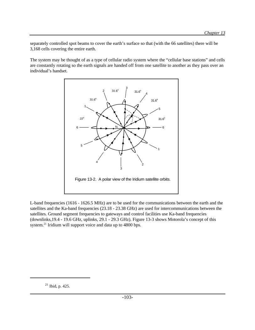
Chapter 13
21 Ibid, p. 425.
-103-
separately controlled spot beams to cover the earth’s surface so that (with the 66 satellites) there will be3,168 cells covering the entire earth.
The system may be thought of as a type of cellular radio system where the “cellular base stations” and cellsare constantly rotating so the earth signals are handed off from one satellite to another as they pass over anindividual’s handset.
L-band frequencies (1616 - 1626.5 MHz) are to be used for the communications between the earth and thesatellites and the Ka-band frequencies (23.18 - 23.38 GHz) are used for intercommunications between thesatellites. Ground segment frequencies to gateways and control facilities use Ka-band frequencies(downlinks,19.4 - 19.6 GHz, uplinks, 29.1 - 29.3 GHz). Figure 13-3 shows Motorola’s concept of thissystem.21 Iridium will support voice and data up to 4800 bps.
Figure 13-2. A polar view of the Iridium satellite orbits.
1
32
5
4
4
32
1
6
5
6 N.
22o
31.6o
31.6o
31.6o31.6o
31.6o
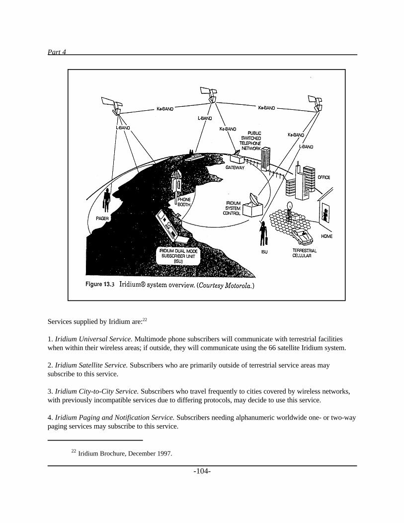
Part 4
22 Iridium Brochure, December 1997.
-104-
Services supplied by Iridium are:22
1. Iridium Universal Service. Multimode phone subscribers will communicate with terrestrial facilitieswhen within their wireless areas; if outside, they will communicate using the 66 satellite Iridium system.
2. Iridium Satellite Service. Subscribers who are primarily outside of terrestrial service areas maysubscribe to this service.
3. Iridium City-to-City Service. Subscribers who travel frequently to cities covered by wireless networks,with previously incompatible services due to differing protocols, may decide to use this service.
4. Iridium Paging and Notification Service. Subscribers needing alphanumeric worldwide one- or two-waypaging services may subscribe to this service.
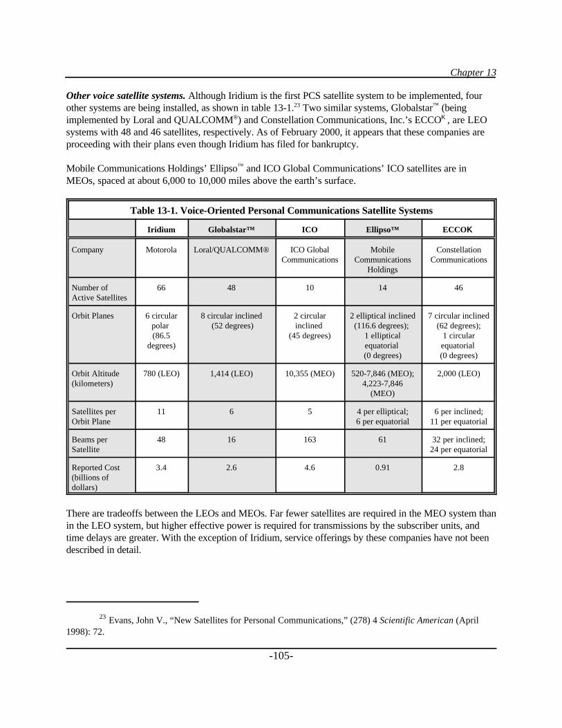
Chapter 13
23 Evans, John V., “New Satellites for Personal Communications,” (278) 4 Scientific American (April1998): 72.
-105-
Other voice satellite systems. Although Iridium is the first PCS satellite system to be implemented, fourother systems are being installed, as shown in table 13-1.23 Two similar systems, Globalstar™ (beingimplemented by Loral and QUALCOMM®) and Constellation Communications, Inc.’s ECCOK, are LEOsystems with 48 and 46 satellites, respectively. As of February 2000, it appears that these companies areproceeding with their plans even though Iridium has filed for bankruptcy.
Mobile Communications Holdings’ Ellipso™ and ICO Global Communications’ ICO satellites are inMEOs, spaced at about 6,000 to 10,000 miles above the earth’s surface.
Table 13-1. Voice-Oriented Personal Communications Satellite Systems
Iridium Globalstar™ ICO Ellipso™ ECCOKK
Company Motorola Loral/QUALCOMM® ICO GlobalCommunications
MobileCommunications
Holdings
ConstellationCommunications
Number ofActive Satellites
66 48 10 14 46
Orbit Planes 6 circularpolar (86.5
degrees)
8 circular inclined (52 degrees)
2 circularinclined
(45 degrees)
2 elliptical inclined(116.6 degrees);
1 ellipticalequatorial (0 degrees)
7 circular inclined(62 degrees);
1 circularequatorial (0 degrees)
Orbit Altitude(kilometers)
780 (LEO) 1,414 (LEO) 10,355 (MEO) 520-7,846 (MEO);4,223-7,846
(MEO)
2,000 (LEO)
Satellites perOrbit Plane
11 6 5 4 per elliptical;6 per equatorial
6 per inclined;11 per equatorial
Beams perSatellite
48 16 163 61 32 per inclined;24 per equatorial
Reported Cost(billions ofdollars)
3.4 2.6 4.6 0.91 2.8
There are tradeoffs between the LEOs and MEOs. Far fewer satellites are required in the MEO system thanin the LEO system, but higher effective power is required for transmissions by the subscriber units, andtime delays are greater. With the exception of Iridium, service offerings by these companies have not beendescribed in detail.
Part 4
24 Ibid, p. 73.
-106-
Pricing of services has not yet been finalized, but it is estimated that prices will be in the range of $3 to $5per minute. Almost all of these companies have Web sites. Visit those sites as the technologies develop toevaluate the use of satellite services as they become operational. Because of the large number ofcommercial providers for both voice and data systems, there will most likely be considerable competitionwhen all of the systems are turned up.
Data Communications Satellites
Since 1992, American Mobile Satellite Corp. has offered SKYCELL® service employing geosynchronoussatellites for communication of data up to 4800 bps. Both voice and data may be handled on the samesystem. One type of use of the SKYCELL® system includes mobile messaging services for large fleets thatcan be used virtually anywhere in North America.. The system uses “L-band” technology with antennasmounted in small domes on the roofs of vehicles to allow for two-way data transmission and positiontracking. Interfaces use standard dispatch application software. The service may be used to send datareports, e-mail, and faxes, as well as to connect to the Internet.
With an OmniQuest portable satellite telephone, notebook computer, portable printer or scanner, and/ordigital camera, public safety personnel can get in touch with national databases or headquarters. Adispatcher can open a voice channel and connect with one or a fleet of mobiles. Communications, accordingto SKYCELL®, are secure. Features include full duplex voice communications, up to 4800 bps datatransmission, 24-hour customer service, voice mail, call forwarding, conference calling, call barring, andland line access to talk groups. SKYCELL® provides dual mode services allowing mobile units to use theirterrestrial service when within their coverage area and to automatically switch over to satellite when theterrestrial system is not available.
Wideband, data-oriented LEO and MEO PCS satellites are being studied and proposed at this time, asshown in table 13-2.24 These satellite systems will have the ability to carry high-speed data around theworld at up to10 gbps.
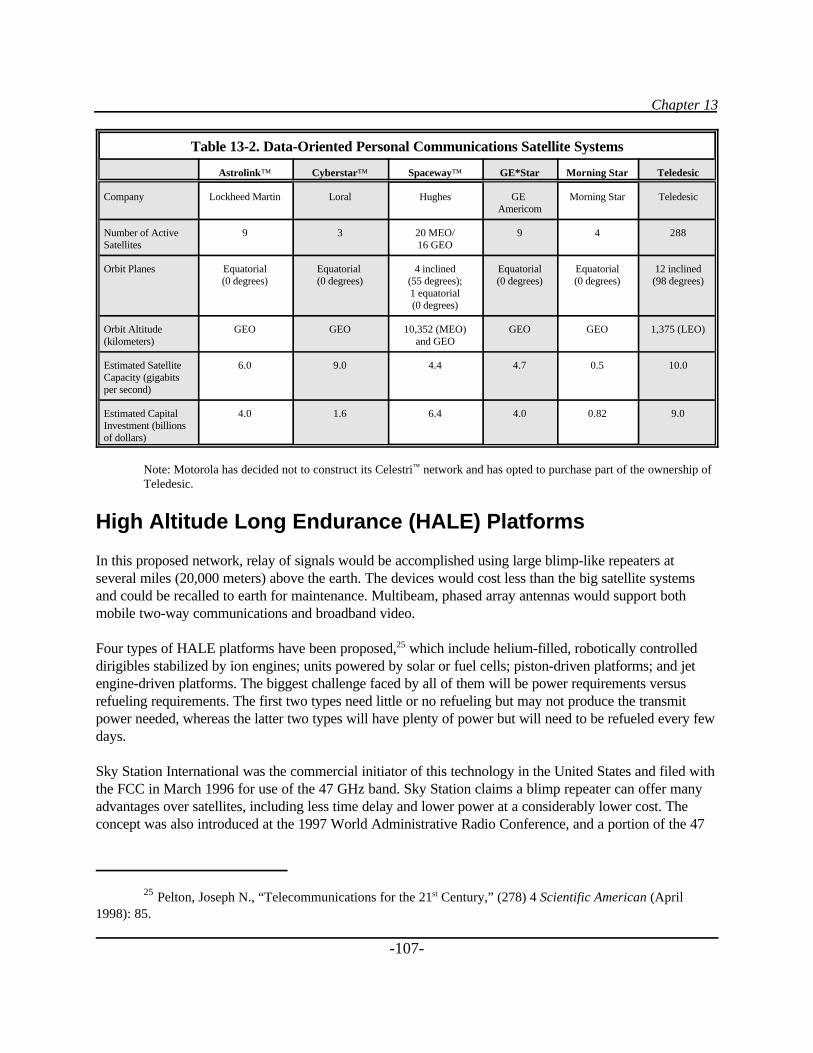
Chapter 13
25 Pelton, Joseph N., “Telecommunications for the 21st Century,” (278) 4 Scientific American (April1998): 85.
-107-
Table 13-2. Data-Oriented Personal Communications Satellite Systems
Astrolink™ Cyberstar™ Spaceway™ GE*Star Morning Star Teledesic
Company Lockheed Martin Loral Hughes GE Americom
Morning Star Teledesic
Number of ActiveSatellites
9 3 20 MEO/16 GEO
9 4 288
Orbit Planes Equatorial(0 degrees)
Equatorial (0 degrees)
4 inclined(55 degrees);1 equatorial(0 degrees)
Equatorial(0 degrees)
Equatorial(0 degrees)
12 inclined(98 degrees)
Orbit Altitude(kilometers)
GEO GEO 10,352 (MEO)and GEO
GEO GEO 1,375 (LEO)
Estimated SatelliteCapacity (gigabitsper second)
6.0 9.0 4.4 4.7 0.5 10.0
Estimated CapitalInvestment (billionsof dollars)
4.0 1.6 6.4 4.0 0.82 9.0
Note: Motorola has decided not to construct its Celestri™ network and has opted to purchase part of the ownership ofTeledesic.
High Altitude Long Endurance (HALE) Platforms
In this proposed network, relay of signals would be accomplished using large blimp-like repeaters atseveral miles (20,000 meters) above the earth. The devices would cost less than the big satellite systemsand could be recalled to earth for maintenance. Multibeam, phased array antennas would support bothmobile two-way communications and broadband video.
Four types of HALE platforms have been proposed,25 which include helium-filled, robotically controlleddirigibles stabilized by ion engines; units powered by solar or fuel cells; piston-driven platforms; and jetengine-driven platforms. The biggest challenge faced by all of them will be power requirements versusrefueling requirements. The first two types need little or no refueling but may not produce the transmitpower needed, whereas the latter two types will have plenty of power but will need to be refueled every fewdays.
Sky Station International was the commercial initiator of this technology in the United States and filed withthe FCC in March 1996 for use of the 47 GHz band. Sky Station claims a blimp repeater can offer manyadvantages over satellites, including less time delay and lower power at a considerably lower cost. Theconcept was also introduced at the 1997 World Administrative Radio Conference, and a portion of the 47
Part 4
-108-
GHz band was tentatively allocated. The 47 GHz band is severely limited by rain, so space diversityground circuits will most likely be required.
The basic concept is to have “very high antenna towers” allowing for very wide-area communications. Thismight be an alternative to backbone microwave terrestrial systems. Sky Station indicated that one couldstart with communications in local areas, expand to regional areas, and eventually cover the country. TheFCC has made no decisions at this time. The concept has many technical and political challenges, and itsdevelopment should be interesting to watch as it evolves.
-109-
SUMMARY
At no time in the history of public safety communications have so many options been available.Technological advances and regulatory changes have combined to make selecting a communications systemvery complex. As we move into the future, it is unlikely to get any better.
NLECTC–Rocky Mountain and other groups [such as the Federal Public Safety Wireless Networkprogram (PSWN)] are dedicated to helping you through the maze of technology jargon and bureaucraticrules as you proceed on your communications project.
We hope this guidebook has been useful to you. We welcome your comments and suggestions forimprovement.

-111-
GLOSSARY AND ACRONYMS
Glossary
-113-
Glossary
Amplifier: A device for obtaining an increase in voltage, current, or power.
Amplitude: The maximum departure of the value of an alternating current or radio wave from the averagevalue.
Analog: A signal that may vary continuously over a specific range of values.
Antenna: A device (usually metallic) for radiating or receiving radio waves.
Band: A well-defined range of wavelengths or frequencies.
Bandwidth: The range within a band of frequencies. A measure of the amount of information that can flowthrough a given point at any given time.
Bit: Abbreviation for binary digit (either a 0 or a 1), the basic unit for storing data in a computer.
Block grant: Federal grant funds that are allocated based on a predetermined statutory formula.
Cavity filter: A device used to shield the receiver from the transmitter and to form a circuit called aduplexer.
Channel: A band of frequencies of sufficient width to allow a single radio communication.
Combiner: A device used to combine the output signals from a number of transmitters connected to thesame antenna (in trunked radio systems).
Coverage: The amount or percentage of area reached by a communications medium.
Cycle: One complete performance of a vibration, electrical oscillation, current alternation, or other periodicprocess.
Digital: Information that can be represented by two discrete states (either 0 or 1). Most information in thespeaking/seeing world is not digital, but must be converted into this form to be used by computers.
Dipole: A radio antenna consisting of two horizontal rods in line with each other, with their ends slightlyseparated.
Discretionary grant: Federal grant funds that are distributed at the discretion of the agency administeringthe funds.
Glossary and Acronyms
-114-
Duplexer: A switching device that allows alternate transmission and reception with the same radio antenna.
Effective Radiated Power: A term for describing radio power levels.
Flowchart: A diagram showing the step-by-step progression through a complicated process or system.
Formula grant: Federal grant funds that are allocated based on a predetermined statutory formula.
Frequency: The number of repetitions of a periodic process in a unit of time.
Frequency multiplier: A device for multiplying the frequency up to a desired output frequency.
Gain: The effectiveness of a directional antenna expressed as the ratio in decibels of standard antenna inputpower to the directional antenna input power that will produce the same field strength in the desireddirection.
Guard band: A nonoverlapping space between radio channels used to minimize interference.
Hertz: Abbreviation for cycles per second.
Implementation team: A group of officials charged with ensuring that a project is planned, managed, andcompleted.
Infrastructure: The underlying permanent installations required for radio communications.
Interference: Confusion of received radio signals due to strays or undesired signals.
Isolator: A device that may be added to the circuit between each transmitter and the combiner and used toincrease the isolation to the other transmitter outputs.
Isotropic radiator: A theoretical antenna that radiates equally in all directions.
Modem: An acronym for modulator/demodulator, which is a device that translates digital signals comingfrom your computer into analog signals that can be transmitted over standard telephone lines. The modemalso translates the analog signal back into a digital signal that your computer can understand.
Modulation: The process of varying the amplitude, frequency, or phase of a carrier or signal in telephone,radio, or television.
Multicoupler: A device used to connect a multitude of receivers to a single antenna.
Noise: An unwanted signal or disturbance (e.g., static) in a radio communications system.
Omnidirectional: Receiving or sending radio waves equally well in all directions.
Glossary
-115-
Oscillator: A device for producing alternating current, specifically for producing radio frequencies.
Polarization: The action or process of affecting radiation so that the vibrations of the wave assume adefinite form.
Propagation: The action of traveling and spreading through space, in reference to wave energy.
Receiver: The portion of a radio device that converts the radio waves into audible signals.
Refarming: An administrative process being conducted by the FCC to reduce channel bandwidths and, as aresult, promote spectrum efficiency.
Repeater: A transmitter and a receiver operating on different frequencies and often connected to a commonantenna.
Skip: The phenomenon by which a radio wave reflects from the ionosphere during the height of the sunspotcycle, often resulting in severe interference problems.
Spectrum: The region of the electromagnetic spectrum in which radio transmission and detectiontechniques may be used.
Spectrum efficiency: The ability to optimize the amount of information sent through a given amount ofbandwidth.
Steering Committee: A group of usually high-level officials charged with setting policy for a project.
Transmitter: The portion of a radio device that sends out the radio signal.
Vocoder: Abbreviation for voice coder, a circuit that samples a voice frequency and then changes thesampled information into binary digits to modulate the carrier.
Wave: A disturbance or variation that transfers energy progressively from point to point in a medium andthat may take the form of a variation in electric or magnetic intensity or electric potential.
Wavelength: The distance in the progression of a wave from any one point to the next point ofcorresponding phase.
Acronyms
-117-
Acronyms
AASHTO American Association of State Highway Transportation OfficialsACSB Amplitude Compandered Single SidebandAM Amplitude ModulationAMPS Advanced Mobile Phone SystemAPCO Association of Public-Safety Communications Officials, InternationalBJA Bureau of Justice AssistanceBJS Bureau of Justice StatisticsCDMA Code Division Multiple AccessCDPD Cellular Digital Packet DataCFR Code of Federal RegulationsCOPS Community Oriented Policing Services COTS Common Off-the-Shelf SoftwareDoD Department of DefenseDOJ Department of JusticeDOT Department of TransportationEHF Extremely High FrequencyEMS Emergency Medical ServiceERP Effective Radiated PowerESMR Enhanced Specialized Mobile RadioFAA Federal Aviation AdministrationFBI Federal Bureau of InvestigationFCC Federal Communications CommissionFCCA Forestry Conservation Communication AssociationFDMA Frequency Division Multiple AccessFEMA Federal Emergency Management AgencyFM Frequency ModulationFSK Frequency Shift KeyingGEO Geosynchronous Earth OrbitGHz Gigahertz (1 billion cycles per second)GPS Global Positioning SystemGSA General Services AdministrationHALE High Altitude Long EnduranceHF High FrequencyHz Hertz (cycles per second)IGA Intergovernmental AgreementIM IntermodulationIMSA International Municipal Signal AssociationJPA Joint Powers AuthorityKHz Kilohertz (1,000 cycles per second)
Glossary and Acronyms
-118-
LCRA Lower Colorado River AuthorityLEAA Law Enforcement Assistance AdministrationLEO Low Earth OrbitLLEBG Local Law Enforcement Block GrantsLOS Line of SightMEO Medium Earth OrbitMHz Megahertz (1 million cycles per second)MIU Mobile Imaging UnitMTSO Mobile Telephone Switching OfficeNAMPS Narrowband Advanced Mobile Phone SystemNASTD National Association of State Telecommunications DirectorsNCIC National Crime Information CenterNCJRS National Criminal Justice Reference ServiceNCS National Communications SystemsNENA National Emergency Number AssociationNIJ National Institute of JusticeNLECTC National Law Enforcement and Corrections Technology CenterNTIA National Telecommunications and Information AdministrationOET Office of Engineering and TechnologyOJJDP Office of Juvenile Justice and Delinquency PreventionOJP Office of Justice ProgramsPBX Private Branch ExchangePCS Personal Communications SystemPLMRS Private Land Mobile Radio ServicesPOCSAG Post Office Standardization Advisory GroupPSCC Public Safety Coordinating CouncilPSTN Public Switched Telephone NetworkPSWN Public Safety Wireless NetworkRF Radio FrequencyRFI Request for InformationRFP Request for ProposalsRFQ Request for QuotationSHF Super High FrequencySIS State Identification SystemsSMR Specialized Mobile RadioTCP/IP Transmission Control Protocol/Internet ProtocolTDMA Time Division Multiple AccessTETRA TErrestrial TRunked RAdioTIIAP Telecommunications and Information Infrastructure Assistance ProgramTOP Technology Opportunities Program (formerly TIIAP)UART Universal Receiver/TransmitterUHF Ultra High FrequencyVHF Very High Frequency

-119-
APPENDIXES

Appendix A
-121-
Appendix AState Agencies Administering Byrne Program
Grants
ALABAMAOffice of the Governor334–242–7100
ALASKAAlaska State Troopers907–269–5082
AMERICAN SAMOACriminal Justice PlanningAgency011–684–633–5221
ARIZONACriminal Justice Commission602–230–0252
ARKANSASSentencing Commission501–682–5018
CALIFORNIAOffice of Criminal JusticePlanning916–324–9163
COLORADODepartment of Public Safety303–239–4400
CONNECTICUTOffice of Policy andManagement860–418–6416
DELAWARECriminal Justice Council302–577–5030
DISTRICT OF COLUMBIAOffice of Grants Managementand Development202–727–6537
FLORIDADepartment of LawEnforcement850–410–7001
GEORGIACriminal Justice CoordinatingCouncil404–559–4949
GUAMGovernor’s Office011–671–472–4201
HAWAIIOffice of the Attorney General808–586–1151
IDAHODepartment of LawEnforcement208–884–7040
ILLINOISCriminal Justice InformationAuthority312–793–8550
INDIANACriminal Justice Institute317–232–1230
IOWADepartment of Public Safety515–281–3211
KANSASCriminal Justice CoordinatingCouncil913–296–0926
KENTUCKYJustice Cabinet502–564–7554
LOUISIANACommission on LawEnforcement225–925–4430
MAINEDepartment of Public Safety207–287–3619
MARYLANDGovernor’s Office of CrimeControl and Prevention410–321–3521
MASSACHUSETTSExecutive Office of PublicSafety617–727–7775
MICHIGANMichigan State Police517–336–6158
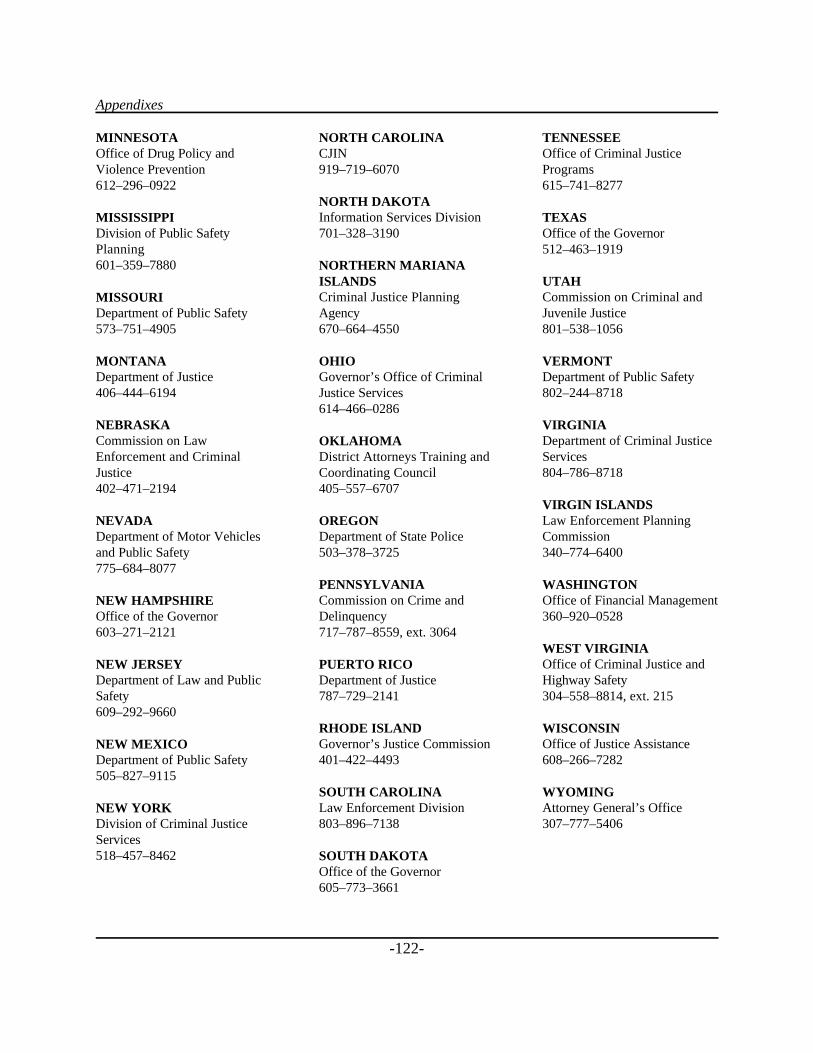
Appendixes
-122-
MINNESOTAOffice of Drug Policy andViolence Prevention612–296–0922
MISSISSIPPIDivision of Public SafetyPlanning601–359–7880
MISSOURIDepartment of Public Safety573–751–4905
MONTANADepartment of Justice406–444–6194
NEBRASKACommission on LawEnforcement and CriminalJustice402–471–2194
NEVADADepartment of Motor Vehiclesand Public Safety775–684–8077
NEW HAMPSHIREOffice of the Governor603–271–2121
NEW JERSEYDepartment of Law and PublicSafety609–292–9660
NEW MEXICODepartment of Public Safety505–827–9115
NEW YORKDivision of Criminal JusticeServices518–457–8462
NORTH CAROLINACJIN919–719–6070
NORTH DAKOTAInformation Services Division701–328–3190
NORTHERN MARIANAISLANDSCriminal Justice PlanningAgency670–664–4550
OHIOGovernor’s Office of CriminalJustice Services614–466–0286
OKLAHOMADistrict Attorneys Training andCoordinating Council405–557–6707
OREGONDepartment of State Police503–378–3725
PENNSYLVANIACommission on Crime andDelinquency717–787–8559, ext. 3064
PUERTO RICODepartment of Justice787–729–2141
RHODE ISLANDGovernor’s Justice Commission401–422–4493
SOUTH CAROLINALaw Enforcement Division803–896–7138
SOUTH DAKOTAOffice of the Governor605–773–3661
TENNESSEEOffice of Criminal JusticePrograms615–741–8277
TEXASOffice of the Governor512–463–1919
UTAHCommission on Criminal andJuvenile Justice801–538–1056
VERMONTDepartment of Public Safety802–244–8718
VIRGINIADepartment of Criminal JusticeServices804–786–8718
VIRGIN ISLANDSLaw Enforcement PlanningCommission340–774–6400
WASHINGTONOffice of Financial Management360–920–0528
WEST VIRGINIAOffice of Criminal Justice andHighway Safety304–558–8814, ext. 215
WISCONSINOffice of Justice Assistance608–266–7282
WYOMINGAttorney General’s Office307–777–5406
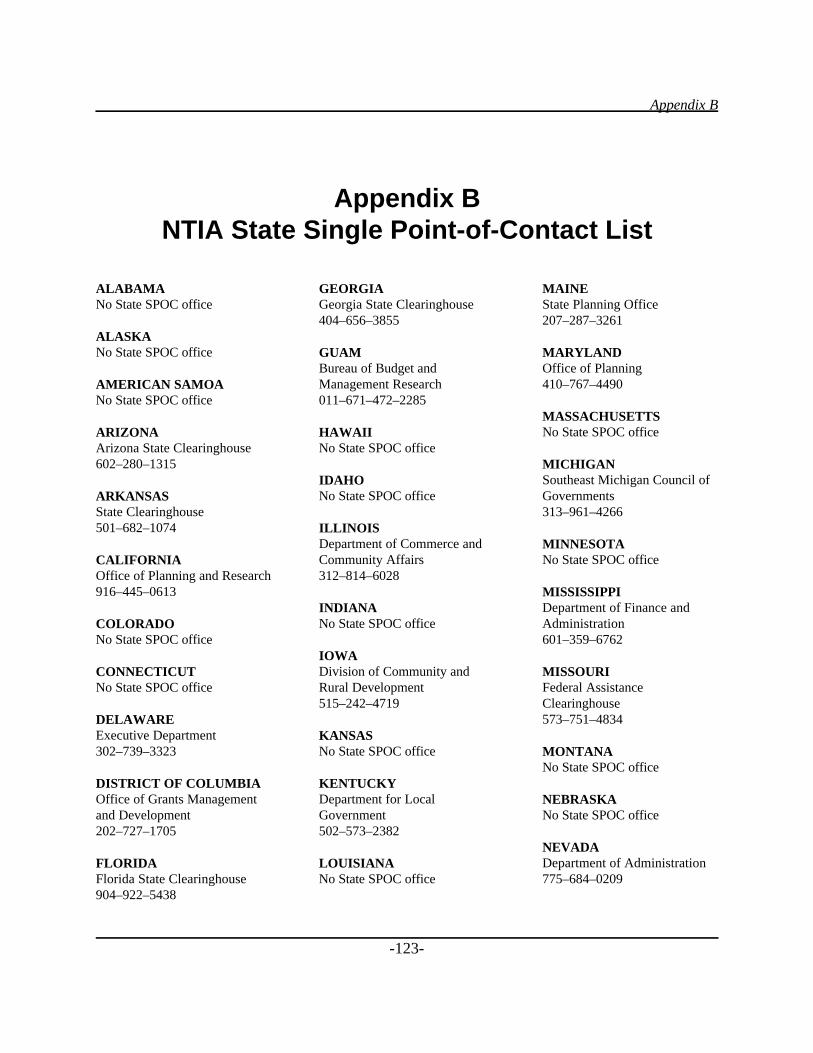
Appendix B
-123-
Appendix BNTIA State Single Point-of-Contact List
ALABAMANo State SPOC office
ALASKANo State SPOC office
AMERICAN SAMOANo State SPOC office
ARIZONAArizona State Clearinghouse602–280–1315
ARKANSASState Clearinghouse501–682–1074
CALIFORNIAOffice of Planning and Research916–445–0613
COLORADONo State SPOC office
CONNECTICUTNo State SPOC office
DELAWAREExecutive Department302–739–3323
DISTRICT OF COLUMBIAOffice of Grants Managementand Development202–727–1705
FLORIDAFlorida State Clearinghouse904–922–5438
GEORGIAGeorgia State Clearinghouse404–656–3855
GUAMBureau of Budget andManagement Research011–671–472–2285
HAWAIINo State SPOC office
IDAHONo State SPOC office
ILLINOISDepartment of Commerce andCommunity Affairs312–814–6028
INDIANANo State SPOC office
IOWADivision of Community andRural Development515–242–4719
KANSASNo State SPOC office
KENTUCKYDepartment for LocalGovernment502–573–2382
LOUISIANANo State SPOC office
MAINEState Planning Office207–287–3261
MARYLANDOffice of Planning410–767–4490
MASSACHUSETTSNo State SPOC office
MICHIGANSoutheast Michigan Council ofGovernments313–961–4266
MINNESOTANo State SPOC office
MISSISSIPPIDepartment of Finance andAdministration601–359–6762
MISSOURIFederal AssistanceClearinghouse573–751–4834
MONTANANo State SPOC office
NEBRASKANo State SPOC office
NEVADADepartment of Administration775–684–0209
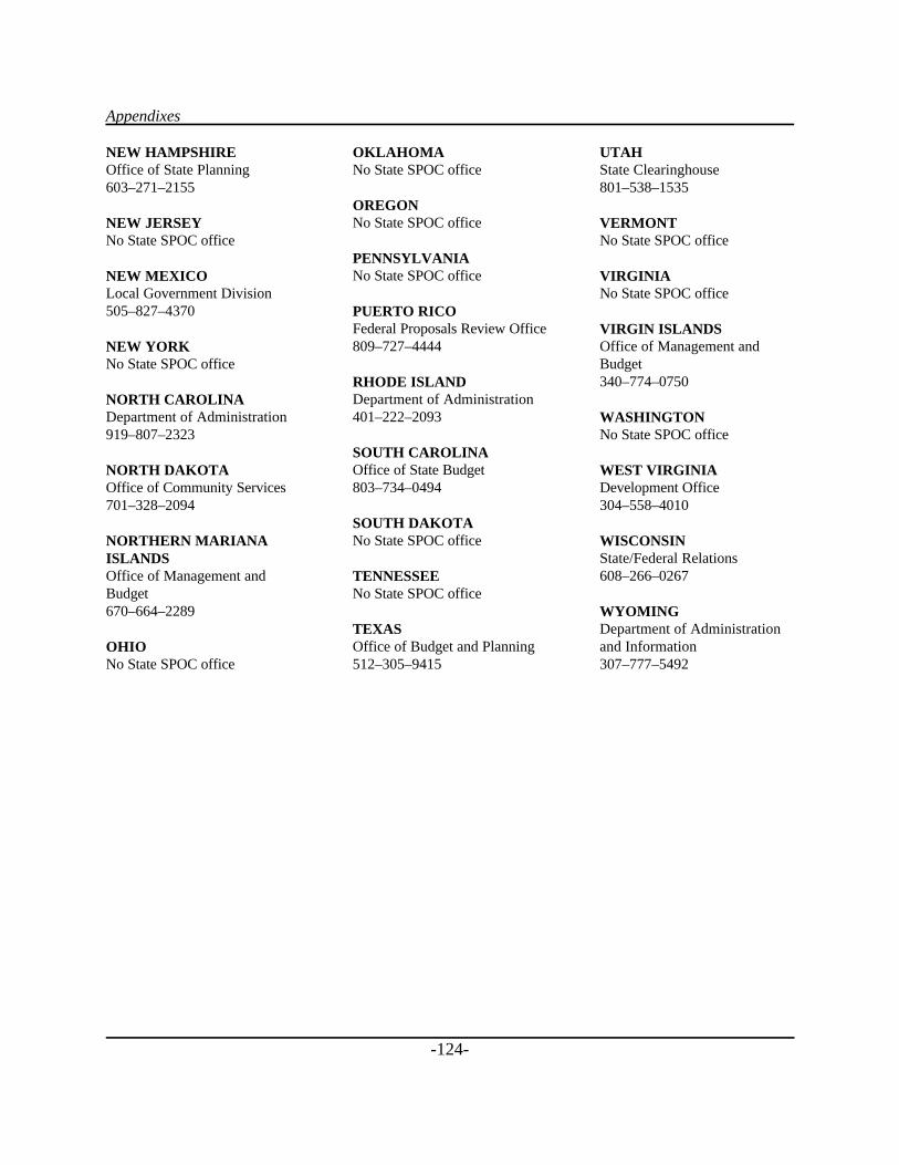
Appendixes
-124-
NEW HAMPSHIREOffice of State Planning603–271–2155
NEW JERSEYNo State SPOC office
NEW MEXICOLocal Government Division505–827–4370
NEW YORKNo State SPOC office
NORTH CAROLINADepartment of Administration919–807–2323
NORTH DAKOTAOffice of Community Services701–328–2094
NORTHERN MARIANAISLANDSOffice of Management andBudget670–664–2289
OHIONo State SPOC office
OKLAHOMANo State SPOC office
OREGONNo State SPOC office
PENNSYLVANIANo State SPOC office
PUERTO RICOFederal Proposals Review Office809–727–4444
RHODE ISLANDDepartment of Administration401–222–2093
SOUTH CAROLINAOffice of State Budget803–734–0494
SOUTH DAKOTANo State SPOC office
TENNESSEENo State SPOC office
TEXASOffice of Budget and Planning512–305–9415
UTAHState Clearinghouse801–538–1535
VERMONTNo State SPOC office
VIRGINIANo State SPOC office
VIRGIN ISLANDSOffice of Management andBudget340–774–0750
WASHINGTONNo State SPOC office
WEST VIRGINIADevelopment Office304–558–4010
WISCONSINState/Federal Relations608–266–0267
WYOMINGDepartment of Administrationand Information307–777–5492
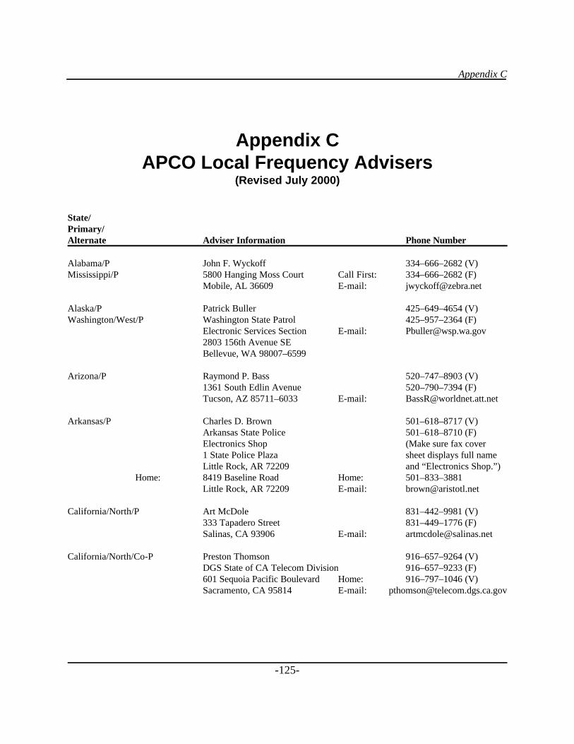
Appendix C
-125-
Appendix CAPCO Local Frequency Advisers
(Revised July 2000)
State/Primary/Alternate Adviser Information Phone Number
Alabama/P John F. Wyckoff 334–666–2682 (V)Mississippi/P 5800 Hanging Moss Court Call First: 334–666–2682 (F)
Mobile, AL 36609 E-mail: [email protected]
Alaska/P Patrick Buller 425–649–4654 (V)Washington/West/P Washington State Patrol 425–957–2364 (F)
Electronic Services Section E-mail: [email protected] 156th Avenue SEBellevue, WA 98007–6599
Arizona/P Raymond P. Bass 520–747–8903 (V)1361 South Edlin Avenue 520–790–7394 (F)Tucson, AZ 85711–6033 E-mail: [email protected]
Arkansas/P Charles D. Brown 501–618–8717 (V)Arkansas State Police 501–618–8710 (F)Electronics Shop (Make sure fax cover 1 State Police Plaza sheet displays full nameLittle Rock, AR 72209 and “Electronics Shop.”)
Home: 8419 Baseline Road Home: 501–833–3881Little Rock, AR 72209 E-mail: [email protected]
California/North/P Art McDole 831–442–9981 (V)333 Tapadero Street 831–449–1776 (F)Salinas, CA 93906 E-mail: [email protected]
California/North/Co-P Preston Thomson 916–657–9264 (V)DGS State of CA Telecom Division 916–657–9233 (F)601 Sequoia Pacific Boulevard Home: 916–797–1046 (V)Sacramento, CA 95814 E-mail: [email protected]
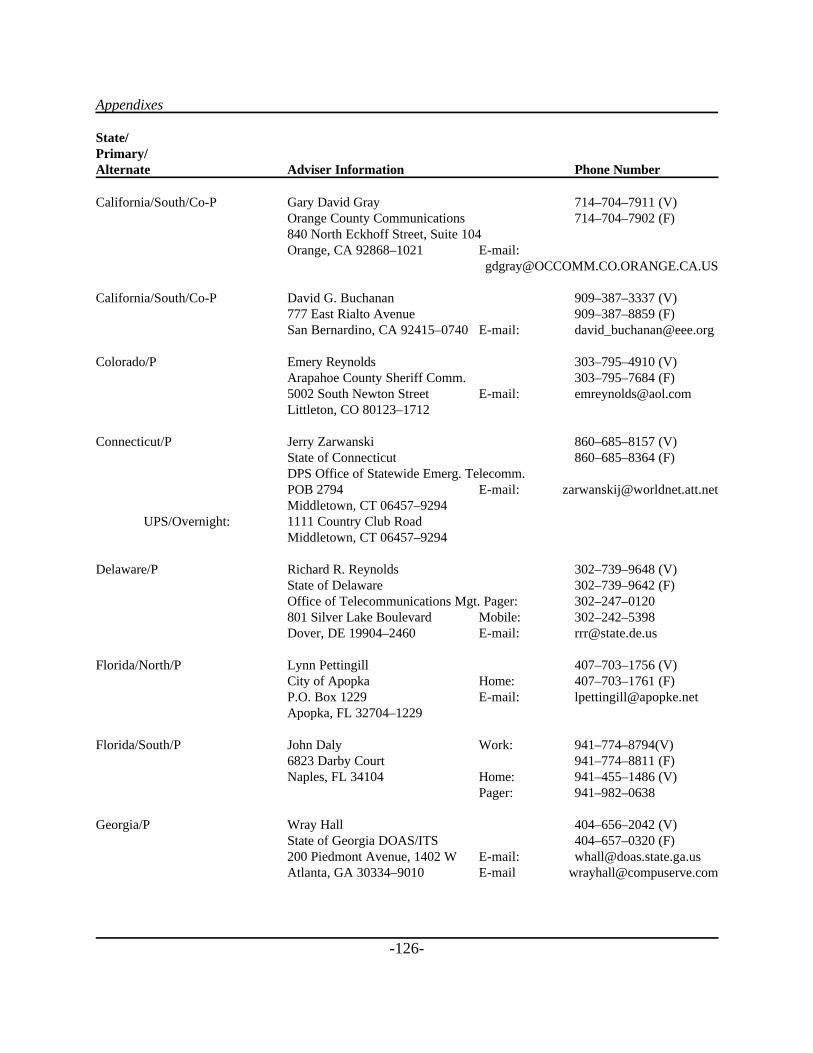
Appendixes
-126-
State/Primary/Alternate Adviser Information Phone Number
California/South/Co-P Gary David Gray 714–704–7911 (V)Orange County Communications 714–704–7902 (F)840 North Eckhoff Street, Suite 104Orange, CA 92868–1021 E-mail:
California/South/Co-P David G. Buchanan 909–387–3337 (V)777 East Rialto Avenue 909–387–8859 (F)San Bernardino, CA 92415–0740 E-mail: [email protected]
Colorado/P Emery Reynolds 303–795–4910 (V)Arapahoe County Sheriff Comm. 303–795–7684 (F)5002 South Newton Street E-mail: [email protected], CO 80123–1712
Connecticut/P Jerry Zarwanski 860–685–8157 (V)State of Connecticut 860–685–8364 (F)DPS Office of Statewide Emerg. Telecomm.POB 2794 E-mail: [email protected], CT 06457–9294
UPS/Overnight: 1111 Country Club Road Middletown, CT 06457–9294
Delaware/P Richard R. Reynolds 302–739–9648 (V)State of Delaware 302–739–9642 (F)Office of Telecommunications Mgt. Pager: 302–247–0120801 Silver Lake Boulevard Mobile: 302–242–5398 Dover, DE 19904–2460 E-mail: [email protected]
Florida/North/P Lynn Pettingill 407–703–1756 (V)City of Apopka Home: 407–703–1761 (F)P.O. Box 1229 E-mail: [email protected], FL 32704–1229
Florida/South/P John Daly Work: 941–774–8794(V)6823 Darby Court 941–774–8811 (F)Naples, FL 34104 Home: 941–455–1486 (V)
Pager: 941–982–0638
Georgia/P Wray Hall 404–656–2042 (V)State of Georgia DOAS/ITS 404–657–0320 (F)200 Piedmont Avenue, 1402 W E-mail: [email protected], GA 30334–9010 E-mail [email protected]
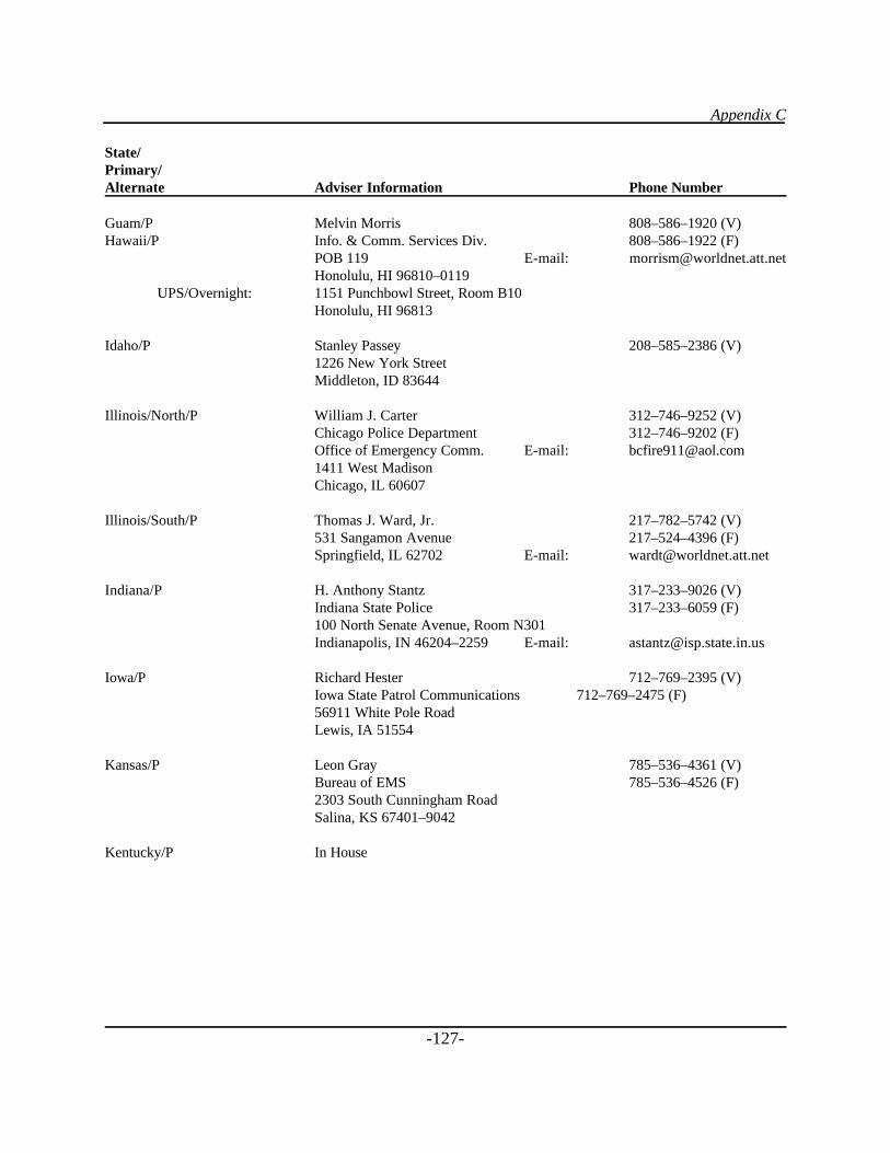
Appendix C
-127-
State/Primary/Alternate Adviser Information Phone Number
Guam/P Melvin Morris 808–586–1920 (V)Hawaii/P Info. & Comm. Services Div. 808–586–1922 (F)
POB 119 E-mail: [email protected], HI 96810–0119
UPS/Overnight: 1151 Punchbowl Street, Room B10Honolulu, HI 96813
Idaho/P Stanley Passey 208–585–2386 (V)1226 New York StreetMiddleton, ID 83644
Illinois/North/P William J. Carter 312–746–9252 (V)Chicago Police Department 312–746–9202 (F)Office of Emergency Comm. E-mail: [email protected] West MadisonChicago, IL 60607
Illinois/South/P Thomas J. Ward, Jr. 217–782–5742 (V)531 Sangamon Avenue 217–524–4396 (F)Springfield, IL 62702 E-mail: [email protected]
Indiana/P H. Anthony Stantz 317–233–9026 (V)Indiana State Police 317–233–6059 (F)100 North Senate Avenue, Room N301Indianapolis, IN 46204–2259 E-mail: [email protected]
Iowa/P Richard Hester 712–769–2395 (V)Iowa State Patrol Communications 712–769–2475 (F)56911 White Pole RoadLewis, IA 51554
Kansas/P Leon Gray 785–536–4361 (V)Bureau of EMS 785–536–4526 (F)2303 South Cunningham RoadSalina, KS 67401–9042
Kentucky/P In House
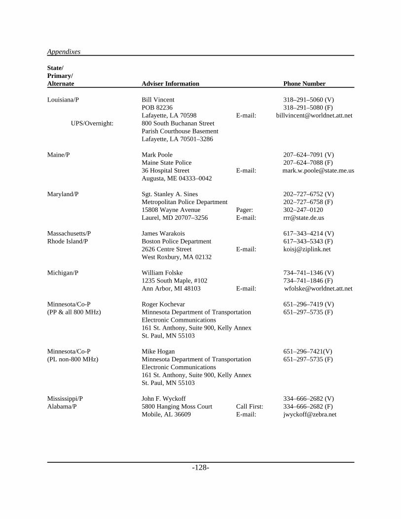
Appendixes
-128-
State/Primary/Alternate Adviser Information Phone Number
Louisiana/P Bill Vincent 318–291–5060 (V)POB 82236 318–291–5080 (F)Lafayette, LA 70598 E-mail: [email protected]
UPS/Overnight: 800 South Buchanan StreetParish Courthouse BasementLafayette, LA 70501–3286
Maine/P Mark Poole 207–624–7091 (V)Maine State Police 207–624–7088 (F)36 Hospital Street E-mail: [email protected], ME 04333–0042
Maryland/P Sgt. Stanley A. Sines 202–727–6752 (V)Metropolitan Police Department 202–727–6758 (F)15808 Wayne Avenue Pager: 302–247–0120Laurel, MD 20707–3256 E-mail: [email protected]
Massachusetts/P James Warakois 617–343–4214 (V)Rhode Island/P Boston Police Department 617–343–5343 (F)
2626 Centre Street E-mail: [email protected] Roxbury, MA 02132
Michigan/P William Folske 734–741–1346 (V)1235 South Maple, #102 734–741–1846 (F)Ann Arbor, MI 48103 E-mail: [email protected]
Minnesota/Co-P Roger Kochevar 651–296–7419 (V)(PP & all 800 MHz) Minnesota Department of Transportation 651–297–5735 (F)
Electronic Communications161 St. Anthony, Suite 900, Kelly AnnexSt. Paul, MN 55103
Minnesota/Co-P Mike Hogan 651–296–7421(V)(PL non-800 MHz) Minnesota Department of Transportation 651–297–5735 (F)
Electronic Communications161 St. Anthony, Suite 900, Kelly AnnexSt. Paul, MN 55103
Mississippi/P John F. Wyckoff 334–666–2682 (V)Alabama/P 5800 Hanging Moss Court Call First: 334–666–2682 (F)
Mobile, AL 36609 E-mail: [email protected]
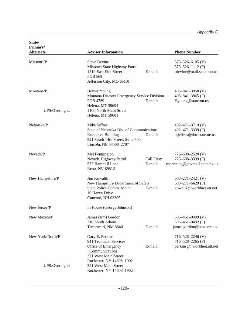
Appendix C
-129-
State/Primary/Alternate Adviser Information Phone Number
Missouri/P Steve Devine 573–526–6105 (V)Missouri State Highway Patrol 573–526–1112 (F)1510 East Elm Street E-mail: [email protected] 568Jefferson City, MO 65101
Montana/P Homer Young 406–841–3958 (V)Montana Disaster Emergency Service Division 406–841–3965 (F)POB 4789 E-mail: [email protected], MT 59604
UPS/Overnight: 1100 North Main StreetHelena, MT 59601
Nebraska/P Mike Jeffres 402–471–3719 (V)State of Nebraska Div. of Communications 402–471–3339 (F)Executive Building E-mail: [email protected] 521 South 14th Street, Suite 300Lincoln, NE 68508–2707
Nevada/P Mel Pennington 775–688–2528 (V)Nevada Highway Patrol Call First: 775–688–3339 (F)557 Hammill Lane E-mail: [email protected], NV 89512
New Hampshire/P Jim Kowalik 603–271–2421 (V)New Hampshire Department of Safety 603–271–6629 (F)State Police Comm. Maint. E-mail: [email protected] Hazen DriveConcord, NH 03305
New Jersey/P In House (George Johnson)
New Mexico/P James (Jim) Gordon 505–461–0499 (V)710 South Adams 505–461–0492 (F)Tucumcari, NM 88401 E-mail: [email protected]
New York/North/P Gary E. Perkins 716–528–2246 (V)911 Technical Services 716–528–2265 (F)Office of Emergency E-mail: [email protected] Communications321 West Main StreetRochester, NY 14608–1902
UPS/Overnight: 321 West Main StreetRochester, NY 14608–1902
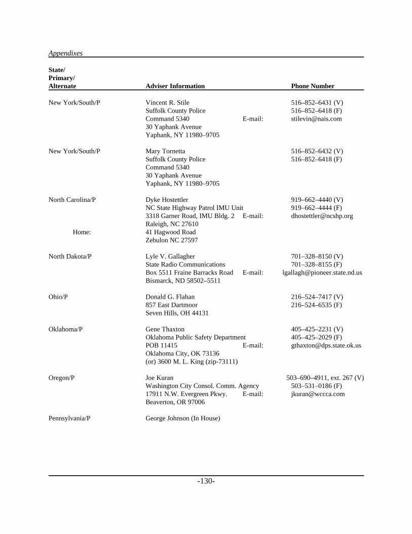
Appendixes
-130-
State/Primary/Alternate Adviser Information Phone Number
New York/South/P Vincent R. Stile 516–852–6431 (V)Suffolk County Police 516–852–6418 (F)Command 5340 E-mail: [email protected] Yaphank AvenueYaphank, NY 11980–9705
New York/South/P Mary Tornetta 516–852–6432 (V)Suffolk County Police 516–852–6418 (F)Command 534030 Yaphank AvenueYaphank, NY 11980–9705
North Carolina/P Dyke Hostettler 919–662–4440 (V)NC State Highway Patrol IMU Unit 919–662–4444 (F)3318 Garner Road, IMU Bldg. 2 E-mail: [email protected] Raleigh, NC 27610
Home: 41 Hagwood RoadZebulon NC 27597
North Dakota/P Lyle V. Gallagher 701–328–8150 (V)State Radio Communications 701–328–8155 (F)Box 5511 Fraine Barracks Road E-mail: [email protected] Bismarck, ND 58502–5511
Ohio/P Donald G. Flahan 216–524–7417 (V)857 East Dartmoor 216–524–6535 (F)Seven Hills, OH 44131
Oklahoma/P Gene Thaxton 405–425–2231 (V)Oklahoma Public Safety Department 405–425–2029 (F)POB 11415 E-mail: [email protected] City, OK 73136(or) 3600 M. L. King (zip-73111)
Oregon/P Joe Kuran 503–690–4911, ext. 267 (V)Washington City Consol. Comm. Agency 503–531–0186 (F)17911 N.W. Evergreen Pkwy. E-mail: [email protected], OR 97006
Pennsylvania/P George Johnson (In House)
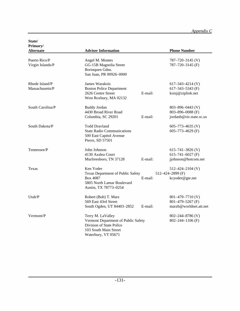
Appendix C
-131-
State/Primary/Alternate Adviser Information Phone Number
Puerto Rico/P Angel M. Montes 787–720–3145 (V)Virgin Islands/P GG-15B Magnolia Street 787–720–3145 (F)
Borinquen Gdns.San Juan, PR 00926–0000
Rhode Island/P James Warakois 617–343–4214 (V)Massachusetts/P Boston Police Department 617–343–5343 (F)
2626 Centre Street E-mail: [email protected] West Roxbury, MA 02132
South Carolina/P Buddy Jordan 803–896–0443 (V)4430 Broad River Road 803–896–0088 (F)Columbia, SC 29201 E-mail: [email protected]
South Dakota/P Todd Dravland 605–773–4635 (V)State Radio Communications 605–773–4629 (F)500 East Capitol AvenuePierre, SD 57501
Tennessee/P John Johnson 615–741–3826 (V)4130 Azalea Court 615–741–6027 (F)Murfreesboro, TN 37128 E-mail: [email protected]
Texas Ken Yoder 512–424–2104 (V)Texas Department of Public Safety 512–424–2899 (F)Box 4087 E-mail: [email protected] North Lamar BoulevardAustin, TX 78773–0254
Utah/P Robert (Bob) T. Marz 801–479–7710 (V)569 East 43rd Street 801–479–5267 (F)South Ogden, UT 84403–2852 E-mail: [email protected]
Vermont/P Terry M. LaValley 802–244–8786 (V)Vermont Department of Public Safety 802–244–1106 (F)Division of State Police103 South Main StreetWaterbury, VT 05671
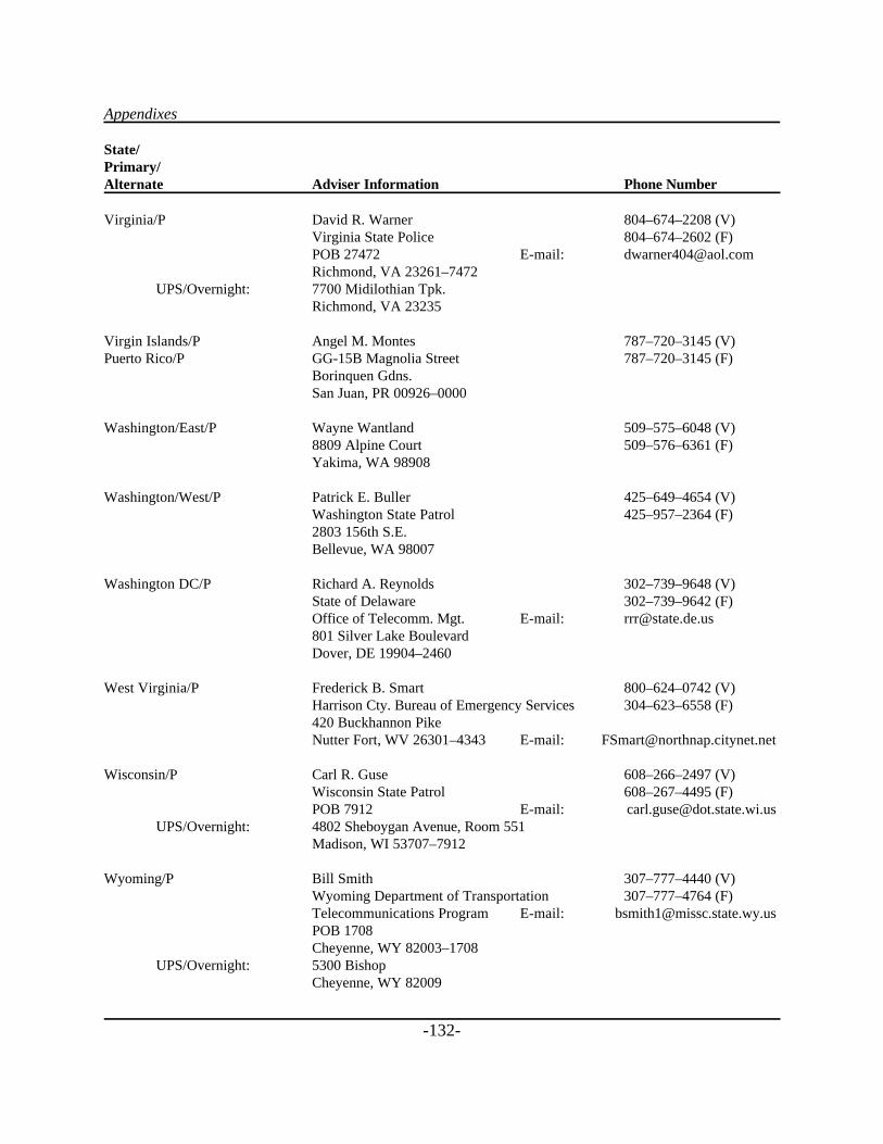
Appendixes
-132-
State/Primary/Alternate Adviser Information Phone Number
Virginia/P David R. Warner 804–674–2208 (V)Virginia State Police 804–674–2602 (F)POB 27472 E-mail: [email protected], VA 23261–7472
UPS/Overnight: 7700 Midilothian Tpk.Richmond, VA 23235
Virgin Islands/P Angel M. Montes 787–720–3145 (V)Puerto Rico/P GG-15B Magnolia Street 787–720–3145 (F)
Borinquen Gdns.San Juan, PR 00926–0000
Washington/East/P Wayne Wantland 509–575–6048 (V)8809 Alpine Court 509–576–6361 (F)Yakima, WA 98908
Washington/West/P Patrick E. Buller 425–649–4654 (V)Washington State Patrol 425–957–2364 (F)2803 156th S.E.Bellevue, WA 98007
Washington DC/P Richard A. Reynolds 302–739–9648 (V)State of Delaware 302–739–9642 (F)Office of Telecomm. Mgt. E-mail: [email protected] Silver Lake BoulevardDover, DE 19904–2460
West Virginia/P Frederick B. Smart 800–624–0742 (V)Harrison Cty. Bureau of Emergency Services 304–623–6558 (F)420 Buckhannon Pike Nutter Fort, WV 26301–4343 E-mail: [email protected]
Wisconsin/P Carl R. Guse 608–266–2497 (V)Wisconsin State Patrol 608–267–4495 (F)POB 7912 E-mail: [email protected]
UPS/Overnight: 4802 Sheboygan Avenue, Room 551Madison, WI 53707–7912
Wyoming/P Bill Smith 307–777–4440 (V)Wyoming Department of Transportation 307–777–4764 (F)Telecommunications Program E-mail: [email protected] POB 1708Cheyenne, WY 82003–1708
UPS/Overnight: 5300 BishopCheyenne, WY 82009
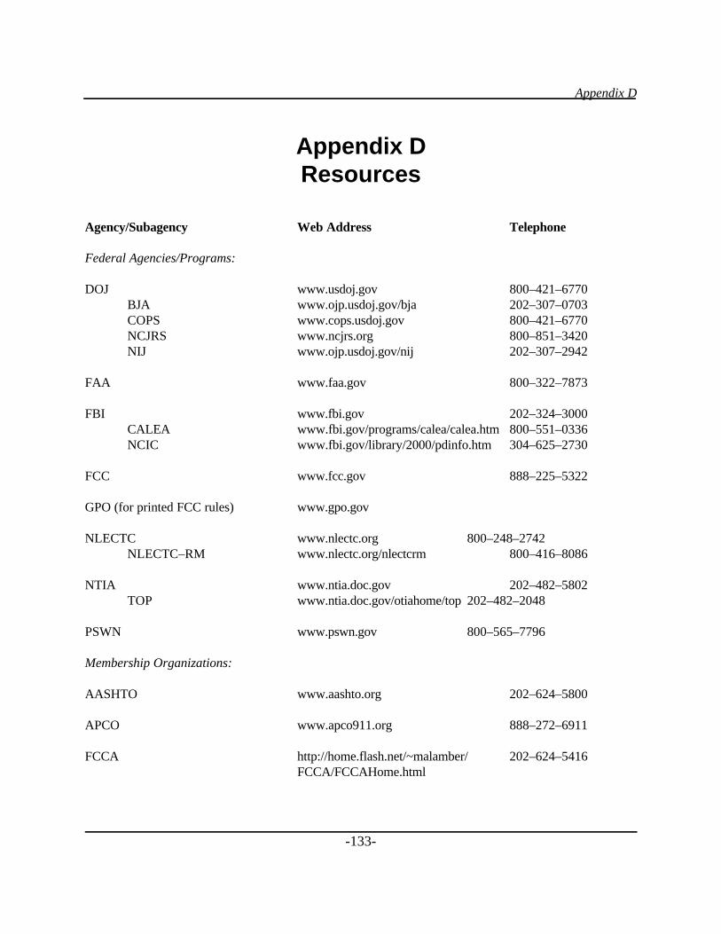
Appendix D
-133-
Appendix DResources
Agency/Subagency Web Address Telephone
Federal Agencies/Programs:
DOJ www.usdoj.gov 800–421–6770BJA www.ojp.usdoj.gov/bja 202–307–0703COPS www.cops.usdoj.gov 800–421–6770NCJRS www.ncjrs.org 800–851–3420NIJ www.ojp.usdoj.gov/nij 202–307–2942
FAA www.faa.gov 800–322–7873
FBI www.fbi.gov 202–324–3000CALEA www.fbi.gov/programs/calea/calea.htm 800–551–0336NCIC www.fbi.gov/library/2000/pdinfo.htm 304–625–2730
FCC www.fcc.gov 888–225–5322
GPO (for printed FCC rules) www.gpo.gov
NLECTC www.nlectc.org 800–248–2742NLECTC–RM www.nlectc.org/nlectcrm 800–416–8086
NTIA www.ntia.doc.gov 202–482–5802TOP www.ntia.doc.gov/otiahome/top 202–482–2048
PSWN www.pswn.gov 800–565–7796
Membership Organizations:
AASHTO www.aashto.org 202–624–5800
APCO www.apco911.org 888–272–6911
FCCA http://home.flash.net/~malamber/ 202–624–5416FCCA/FCCAHome.html

Appendixes
-134-
IMSA www.imsasafety.org 800–723–4672
NENA www.nena9-1-1.org 800–332–3911