Embed Size (px)
Citation preview

Underwater Revolution Inc.
ROV Tricolor Turtle RS-01
Adonis CaraballoCFO
KimberlyBracamonte
CEO
Company Members
Carlos MarínDesign Engineer
Macgregori BriceñoROV Pilot
Asociación Civil “La Nueva Vecindad”Caracas, VenezuelaJune 2013
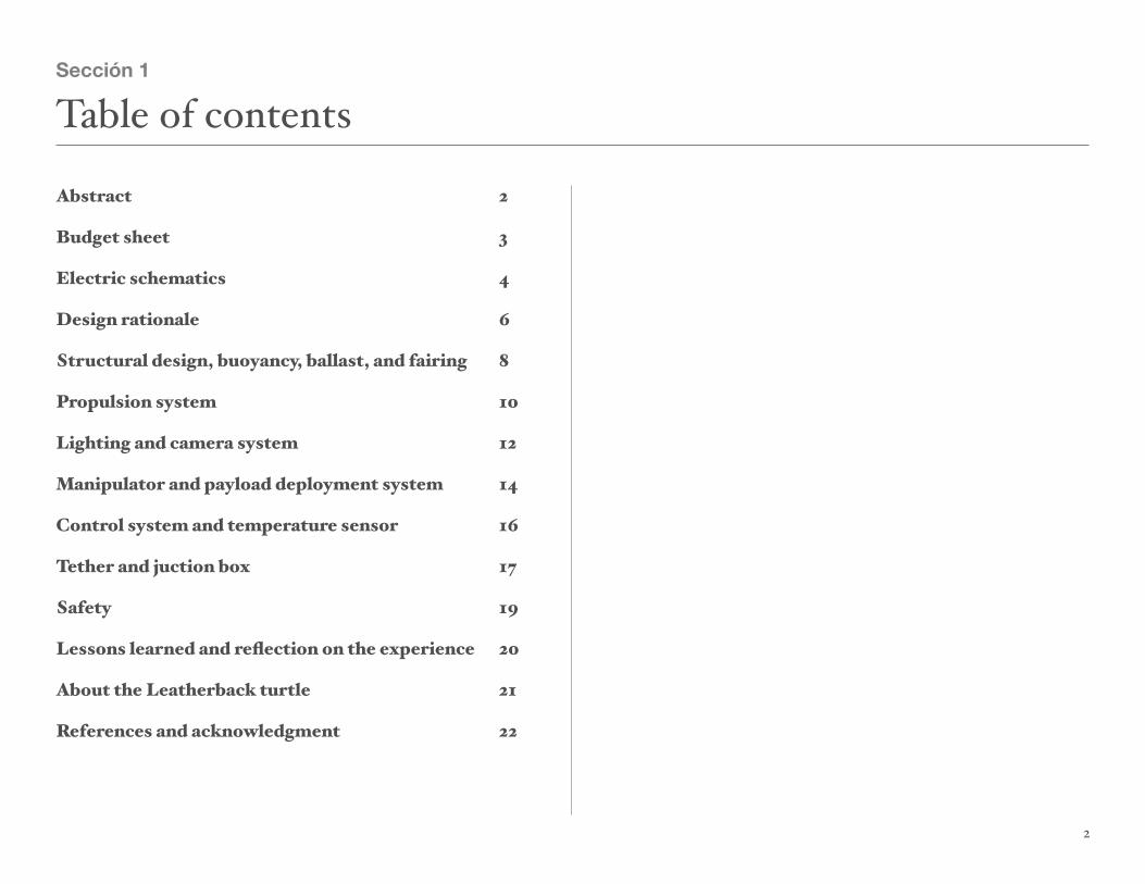
Abstract!! ! ! ! ! ! ! ! ! 2
Budget sheet! ! ! ! ! ! ! ! ! 3
Electric schematics! ! ! ! ! ! ! 4
Design rationale! ! ! ! ! ! ! ! 6
Structural design, buoyancy, ballast, and fairing! 8
Propulsion system!! ! ! ! ! ! ! 10
Lighting and camera system! ! ! ! ! 12
Manipulator and payload deployment system! ! 14
Control system and temperature sensor! ! ! 16
Tether and juction box! ! ! ! ! ! ! 17
Safety! ! ! ! ! ! ! ! ! ! 19
Lessons learned and reflection on the experience! 20
About the Leatherback turtle! ! ! ! ! 21
References and acknowledgment! ! ! ! 22
2
Sección 1
Table of contents
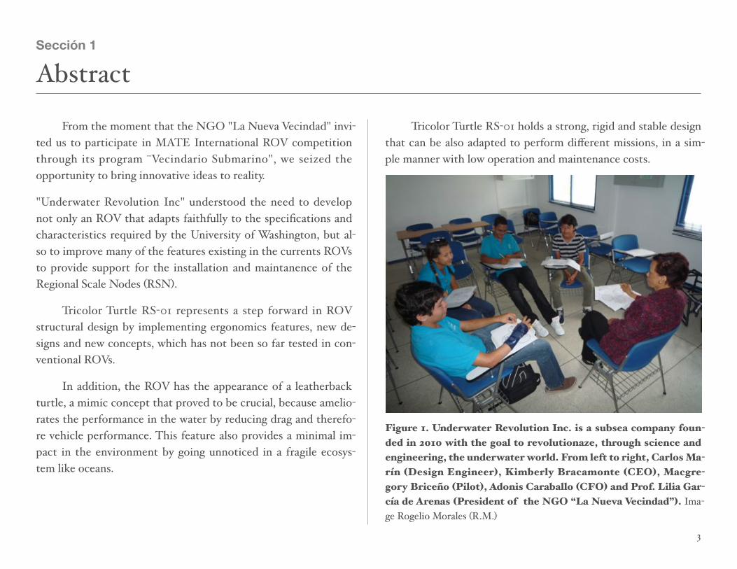
! From the moment that the NGO "La Nueva Vecindad" invi-ted us to participate in MATE International ROV competition through its program ¨Vecindario Submarino", we seized the opportunity to bring innovative ideas to reality.
"Underwater Revolution Inc" understood the need to develop not only an ROV that adapts faithfully to the specifications and characteristics required by the University of Washington, but al-so to improve many of the features existing in the currents ROVs to provide support for the installation and maintanence of the Regional Scale Nodes (RSN).
! Tricolor Turtle RS-01 represents a step forward in ROV structural design by implementing ergonomics features, new de-signs and new concepts, which has not been so far tested in con-ventional ROVs.
! In addition, the ROV has the appearance of a leatherback turtle, a mimic concept that proved to be crucial, because amelio-rates the performance in the water by reducing drag and therefo-re vehicle performance. This feature also provides a minimal im-pact in the environment by going unnoticed in a fragile ecosys-tem like oceans.
! Tricolor Turtle RS-01 holds a strong, rigid and stable design that can be also adapted to perform different missions, in a sim-ple manner with low operation and maintenance costs.
Figure 1. Underwater Revolution Inc. is a subsea company foun-ded in 2010 with the goal to revolutionaze, through science and engineering, the underwater world. From left to right, Carlos Ma-rín (Design Engineer), Kimberly Bracamonte (CEO), Macgre-gory Briceño (Pilot), Adonis Caraballo (CFO) and Prof. Lilia Gar-cía de Arenas (President of the NGO “La Nueva Vecindad”). Ima-ge Rogelio Morales (R.M.)
3
Sección 1
Abstract

4
Sección 2
Budget sheet
PART TOTAL COST (BSF) DONATIONS (BSF)DONATIONS (BSF)
1/2 inch PVC pipes and fittings 5,500.00
Stailess steel screws, bolts and nuts 1,450.00
Polyurethane painting 2,000.00
3/4 inch PVC pipes, fittings and caps 1,100.00
2 inch PVC pipes, caps and universal coupling 8,750.00
CMOS and CCD cameras 2,350.00
Cables (UTP, #10 AWG, twisted pair), PG9 and PG 16 3,250.00
Poly(methyl methacrylate) 5mm and 10mm plates 3,000.00
Robotic claw - MKII 350.00
Hermetic-sealed plastic containers 360.00
Bilge pumps 750 & 1100 GPH 8,000.00
Plastic propellers 1,750.00
Electric fan motor 200.00
Solenoides 190.00
Electric automotive antenna 1,200.00
Epoxy resin 1,800.00
Black heat shrink 2,000.00
Plaster bandages 1,650.001,650.00
Expanded rubber 1,200.00
PCB boards and components 4,000.00
T1o 1W LED lights 2,340.00
TOTAL 52,440 BsF.52,440 BsF. $1,850.00

10A H-Bridge PCB Motor Controller
To control eight 12V DC motors
SPDT 12V relays
To control 3 circuits: cameras & lighting, SIA and ADCP deplo-yment system
12V to 9V DC to DC converter circuit
For UNIT-T UT33 multimeter power supply
5
Sección 3
Electric schematics


Design rationale
! The underwater robot Tricolor Turtle RS-01, is the result of a brainstorming session among members of the company "Under-water Revolution Inc." whose primary purpose was to design and build a remotely operated vehicle (ROV) to fulfill the mission described by our customers, the University of Washington.
! In a series of well-argued debates, intrinsic characteristics of our organization, the best ideas and concepts where confron-ted to produce an optimal solution to meet the requirements and needs of our clients. In this particular case, the University of Wa-shington requires our services to install and maintenance the Re-gional Scale Nodes, a part of the Ocean Observatories Initiative (OOI). There were two proposals that fully complied with the description of the mission but differed, significantly, in their con-cept. The first proposal incorporated within the structure of the vehicle, all the tools needed to execute the mission, similar to a heavy lift helicopter (Figure 2).
! This presented many advantages, like drag reduction by im-plementing a streamlined fairing, payload safety, easy deployment of the Scientific Assembly Interface (SIA) and the new Acoustic Doppler Current Profiler (ADCP) and easy retrieval of the old ADCP. The variations in ROV buoyancy due to the release of the payload, be offset by an equivalent weight in water which would be activated at the time of release of scientific instruments The ROV will hold its cargo up and tight against its center spine to lessen drag and will also eliminate the pendulum effect when mo-ving forward.
Figure 2. The Sikorsky CH-54 Tarhe is a twin-engine heavy-lift helicopter designed by Sikorsky Aircraft for the United States Army. Wikimedia Commons.
! The latter proposal deploy the basket in the seabed, equidis-tant from the location of the mission tasks. Among the advanta-ges posed by the promoters of the idea were its easy handling of instruments and mission execution time reduction. Finally was selected option No. 1, as option No. 2 proved not offer advanta-ges in reducing the mission execution time and also increased the possibility of errors when moving from the basket to mission site.
7

! Defined the ROV basic concept, we proceeded to enumera-te the features that would be incorporate in the concept design, to guarantee the achievement of our goals:
1.Easy assembly, maintenance, repair and operation.
2.Excellent maneuverability.
3.Forward, backward, up, down, turn and pitch and lateral move-ments.
4.Mimic capabilities to minimize environment disruption.
5.Strong, rigid and stable structure.
6. A drag efficient shape.
7.Depth perception for manipulator control.
8.Easy and safety deployment of scientific instruments.
The Leatherback Turtle (Dermochelys coriacea)
! It was decided the shape of a Leatherback turtles for many reasons. First, they have the most hydrodynamic body design of all sea turtles, with a large teardrop-shaped body. Second, they are one of the deepest marine animals diving (depths as great as 1280 meters). Third, they are also the fastest moving reptiles at 35.28 kilometers per hour (The 1992 edition of the Guinness Book of Records). Fourth, despite its lack of a hard shell, it faces enormous predators such as orcas, great whitesharks and tiger sharks. Fifth, curiously leatherback turtles are species with a glo-bal distribution, nesting in the east coast of Venezuela (where we
are located) and can be found in the coast of Washington (where we are competing). A robotic platform that mimic these species of turtles can be an invaluable tool for scientist and researchers.
Figure 3. Leatherback Turtle (Dermochelys coriacea), German Oceanographic Museum, Stralsund. Wikimedia Commons.
! Underwater Revolution Inc. is a company with four year experience in underwater robotics. Our origins relate to our first project “ROV in a Bag” with the MATE Center in 2010.
Figure 4. ROV Green Turtle 1.0. A.C. La Nueva Vecindad. R.M.
8

Structure
! The structure of Tricolor Turtle RS-01 was designed taking into account that it has to be strong, rigid and stable, both under-water and on the surface, and with a modular configuration to en-sure easy access, maintenance and repair. To guarantee a structu-ral design that could achive our goals, the concept of “truss” was incorporated in the design. Truss is a structure comprising one or more triangular units constructed with straight members whose ends are connected at joints referred to as nodes. Trusses are composed of triangles because of the structural stability of that shape and design. A triangle is the simplest geometric figure that will not change shape when the lengths of the sides are fixed.
Figure 5. The Eiffel Tower, an iron lattice tower located in Paris, Fra n ce , i s a p e r f e c t example of truss imple-mentation. These effi-cent design allows the tower to reach an ama-zing 324.00 m height. Wikimedia Commons.
Figure 6. First PVC prototype of the ROV Tricolor Turtle RS-01. The structure was built around the SIA. R. M.
! This ensured a structure with very good features to com-pressive, torsional, tensile, bending and shear forces. Truss can also be designed with large internal spaces, without compromi-sing strength, allowing to incorporate the diversity of elements defined in the concept design. Structural CAD design was develo-ped later using the software Google Sketch Up 8 (Figure 7).
Modular features
9
Sección 1
Structural design, buoyancy, ballast and fairing

! Tricolor Turtle RS-01 was designed to be modular. The vehicle can be separated in three sections, yellow (front), blue (middle) and red (rear). Each of them is conected with eight cou-pling devices that consist of 1/2 inch PVC pipe and 1/2 inch PVC coupling. The PVC pipe is filled with epoxy resin (to strengthen the coupling) and drilled later to place stainless steel bolts and butterfly nut to secure and disassemble the structure (Figure 8). Another feature is the attachment device to place cameras and lights (Figure 8).
Figure 7. CAD structural design in Google Sketch Up 8. Truss im-plementation is evident in Tricolor Turtle RS-01 structure. R M.
Boyancy
! The flotation system is formed by all airtight containers, dis-tributed throughout the robot in the front, middle and rear sec-
tions. These elements produce buoyancy symmetrically to the longitudinal axis of the robot, which ensures horizontal stability. Ballast is achieved by lead fishing weights.
Figure 8. Left, coupling device. Right, attachment device. R.M.
Fairing
! The vehicle possess a sreamlined fairing, that emulates a letherback turtle. The purpose is to reduce drag and preserve all ROV system and scientific payload. The fairing was made of fiber-glass with plastic fins, in order to get a leatherback shape. A mold was made around the PVC structure with plaster bandages, then removed and covered with fiberglass and resin. Finally we painted the structure with polypropylene paint.
Fi g u re 9 . L e f t , applying the plaster b a d g e s t o t h e R OV structure to create the m o l d . R i g h t , R OV fiberglass fairing. R.M.
10

Thrusters
! Thruster were implemented to provide the range of possi-ble maneuvers required by the concept design. Two motors for moving in the horizontal plane, two motors for vertical and late-ral movements, and a fifth motor for rotation about the sideways horizontal axis or pitching. A Bilge Pump from Johnson Pump of 750 GPH 12V 3 A model 3270 for the ptching. Four Bilge Pump from Fuan Aidi Electric Co.Ltd of 1100 GPH 12V model SFBP1-G1100-01 for horizontal and vertical thrusters (Figure 10).
Figure 10. Johnson Pump 750 GPH bilge pump (left) and Fuan Aidi Electric Co.Ltd 1100 GPH bilge pump (right). R.M.
Thruster covert
! The thruster coverts were made with two 2 inch PVC cap secured to the structure with an attachment made of 1/2 inch PVC tee and filled with epoxy resin to reinforce it. Vertical thrus-ter were secured with a stainless steel hose clamps and horizonal thruster with stainless steel bolts and butterfly nuts (Figure 11). The idea was to build a strong thruster covert, durable, detacha-ble and with a better hydrodynamic shape.
Figure 11. Horizontal thruster covert (left). Vertical thruster co-vert (right). R.M.
11
Sección 2
Propulsion system

Propellers
! Initially, a SM 9101-21 tail blade (black) for SM 9101 Heli-copter was chosen as ROV propeller. But when the time came to test its performance, it was drawing, in forward mode, around 7.00 A. This put in risk the mission. At the last moment, the Octura 1250 glass filled plastic were tested in order to find a better thrust vs amperage ratio (Figure 12). The results (Table 1 and II) proved that Octura 1250 was the right choice.
Figure 12. SM 9101-21 tail blade (black) for SM 9101 Helicopter (left) and Octura 1250 glass filled plastic propeller (right) during Bollard pull test. R.M.
Pitching
! Beacuse of limitations in microcontroller expertise (for ins-tance, servo motor), it was necessary to find another way to in-crease the robotic claw limited movility for reaching, grabing or positioning objects during the mission. To achieve that purpose,
a 750 GPH Bilge Pump thruster was placed in the vehicle rear, to produce a rotation about the sideways horizontal axis that will allow the ROV to pitch up and down like a seesaw. Moreover, it brings the ability to submerge without vertical thruster, pitching the ROV nose down and forward the horizontal thrusters. The rear thruster improved, significally, ROV manoeuvrability.
12
Table IBilge Pump 1100 GPH
Table IBilge Pump 1100 GPH
Table IBilge Pump 1100 GPH
Table IBilge Pump 1100 GPH
Table IBilge Pump 1100 GPH
Table IBilge Pump 1100 GPH
PropellerAmp
No loadAmp
ForwardAmp
ReverseThrust
ForwardThrust
Reverse
Octura 1250 0.62 A 4.50 A 4.30 A 6.87 N 6.47 N
9101-15mm 0.62 A 7.00 A 6.95 A 6.18 N 4.71 N
9101-25mm 0.62 A 6.66 A 6.80 A 5.49 N 4.91 N
Table IIBilge Pump 750 GPH
Table IIBilge Pump 750 GPH
Table IIBilge Pump 750 GPH
Table IIBilge Pump 750 GPH
Table IIBilge Pump 750 GPH
Table IIBilge Pump 750 GPH
PropellerAmp
No loadAmp
ForwardAmp
ReverseThrust
ForwardThrust
Reverse
Octura 1250 0.55 A 4.00 A 3.72 A 6.87 N 6.28 N
9101-15mm cut
0.55 A 5.44 A 5.33 A 3.92 N 3.63 N
9101-25mmcut
0.55 A 5.20 A 5.19 A 4.32 N 3.04 N

! Tortuga Tricolor RS-01 uses four cameras and three LED arrays to acomplish every task in the mission.
Cameras
! Two color cameras CMOS 480 TVL 12V DC with a 3.6 mm lens, 500 mA by TTM Limited model TTM-828. One camera lo-cated in the front for panoramic view, the second one for rear view of the scientific payload (SIA and ADCPs). With the last one, lights and cameras were placed in the same pressure housing because of space limitations in the vehicle rear.
Figure 13. Left, rear CMOS 480 TVL camera integraded with a T10 high intensity LED array. Right, rear pressure housing that contains them. R.M.
Figure 14. Left, vehicle front cameras and lights. Right, presuure housing and LEDs array. R.M.
! A pair of color cameras with a 1/3 inch CCD, 600 TVL with a 3 ,6 mm lens, 12V DC 500 mA by LineMak model LS-4059CGN, used in CCTV systems. They were adapted to be use in the stereoscopic vision system.
Lighting systems
! Tortuga Tricolor RS-01 uses two arrays of seven T10 1W ultra bright SMD 5050 LEDs embed in black expanded rubber for front lighting. According to the manufacturer, a high inten
13
Sección 3
Lighting and camera system

Figure 15. Pilot Macgregori Briceño soldering the LEDs array. (left). Inside view of the LEDs array embend in black expanded rubber (right). R.M.
sity white light LED produces a luminous flux between 168-194 lumen, enough light to illuminate the scene. In adition, lights can be rotated around the X and Z axes to achieve a better illumina-tion. Both systems, cameras and lighting, are easy to repair or re-place thanks to a BNC plug connector adapter for video signal and a 2.1mm DC plug power adapter connector for power suply.
3D vision
! In order to improve pilot view during the use of the maniu-lator and given the importance of this tool in the mission, a ste-reoscopic system was developed to achieve a 3D vision and a sense of depth perception. To secure and align the cameras, per-manently, an acrylic plate of 10mm thick was used to embed ca-meras container. It is mandatory to keep both cameras perfectly align to attain a stereoscopic video. The stereoscopic cameras, as we mentioned before, are CCD color cameras with 600TVL re-solution.
! To capture stereoscopic 3D video, a free available software called “Stereoscopic Multiplexer” from www.3dtv.at was used. Ste-reoscopic Multiplexer is a Windows driver that allows you to cap-ture stereoscopic video from two separate cameras. We use a fea-ture of Stereoscopic Multiplexer to get stereoscopic previews. It is also posible with this feature, to align and setup the video ca-meras.
! The resulting 3D video is watched using anaglaphic red and cyan lenses. When viewed through the "color-coded" "anaglyph glasses", each of the two images reaches one eye, revealing an in-tegrated stereoscopic image. The visual cortex of the brain fuses this into perception of a three dimensional scene or composi-tion.
Pressure housing
! The sealed containers were implemented to ensure the her-meticism of electrical and electronic components in the vehicle. These containers are made of two materials, Polyvinyl chloride (PVC) and Polycarbonates (PC). For lights and cameras systems, the pressure housing uses two inches PVC pipe with two inches PVC caps and two inches PVC universal coupling. For viewport, Poly (methyl methacrylate) (PMMA). This is a concept taken from www.homebuiltrovs.com. Lock & Lock hermetically-sealed containers were used for the juctions box (1 lt) and for the PCB H-bridges (2 lt). To insert cables inside the container, white plas-tic PG9 waterproof cables glands connector were used (PG-9 and PG 16).
14

Manipulator
! A Robotic Claw MKII was adapted to be use as manipula-tor in Tricolor Turtle RS-01 . To close and open the robotic claw, a Tamiya dual gearbox kit model 70168 with the configuration for 114.7 to 1 gear ratio was used. The DC motor that came with the kit was substituted because of its low voltage operation (3-6 V) with a 12V DC motor (taken from an electric fan and later WP sealed) . The claw was placed in an extension boom made of 1/2 and 3/4 PVC pipe with a drill bit depth gauge as linear gear. The purpose was to mantain the manipulator close enough to the structure while the ROV is navigating (hydrodynamics), and to extend the boom when is required by the task (Figure 16)
Figure 16. Robotic Claw MKII and extension boom (left). Gear box modification and motor assem-bly (right). R.M.
Payload deployment system
! Tricolor Turtle RS-01 was designed around the Scien-tific Assembly Interface (SIA) and that is the reason to ha-ve a ROV with those dimensions. It was a priority for our company to guarantee that the SIA would be safe and tie inside the structure, and also, could be released easily with copilot command. The SIA deployment system was built on a 10mm thick Poly(methyl methacrylate) (PMMA) plate, attached to the structure with two alumi-num angles. Over the plate, it was set a trigger system that consists of a 12V universal automotive solenoide (Mul T Lock), two plastic pulley and a PVC latch conec-ted with a nylon thread to the solenoide. To fasten the SIA to the deployment system, expanded rubber was added beneath the PMMA plate. The SIA passes through a small groove in the plate and is locked with the latch. When the vehicle is in position over the Backbone Inter-face Assembly (BIA), the solenoide is triggered and the latch retracted causing the deployment of the SIA. After been triggered, the PVC latch returns to its initial posi-tion helped by a metal spring inside the latch (Figure 17).
15
Sección 4
Manipulator and payload deployment system

Figure 17. General view of the SIA deployment system (top). Sole-noide waterproof sealed with epoxy resin (bottom left and right). R.M.
! For the deployment of the new Acoustic Doppler Current Profiler (ADCP) a similar system was used, in this case, in a verti-cal position and with modified aluminum tiger carabiner key-chain as a release device (Figure 18). Both deployment systems for the SIA and the ADCP are robust and reliable.
Figure 18. Aluminum tiger carabiner keychain used for the ADCP deployment system (left). General view of the ADCP deployment system (right). R.M.
! To retrieve the old ADCP from the cradle, an electric auto-tive antenna was adapted (waterproof sealed) with a carabiner keychain on top (as a hook) to grab the ADCP and secure it, and then bring it inside the ROV structure (Figure 19). The pilot can see the hook using the right 600TVL high resolution color came-ra.
Figure 19. ADCP retrieval system. All deployment and retrieval systems are located w i t h i n t h e b l u e s e c t i o n (middle) of the vehicle. R.M.
16

Motor controller PCB and relays
Fi g u re 2 0. 1 0 A H-b r i d g e m o t o r c o n t ro l l e r P C B f ro m PyroElectro.com. R.M.
! This year, “Underwater Revolution Inc.” implemented the use of printed circuit board (PCB) in its ROVs. Previously, DPDT switches and DPDT relays were used in every mayor pro-ject. But in order to grow as a company, an advanced electronic training was given during four days to all company members. H-bridge PCBs were used primarly to control DC motors
forward/reverse direction. This applies to five thrusters (move-ment), two manipulator motors and one motor for the ADCP re-trieval system (electric automotive antenna). For switching on/off lights and cameras, SIA and ADCP deployment systems, three 12V Single Pole Double Throw (SPDT) automotive-style relays were used.
! The 10A H-bridge motor controller PCB design was taken from www.pyroelectro.com (Figure 20). In this website, all the steps, descriptions and materials to build the PCB are explained clearly and in an easy manner. The design uses darlington pair BJT power transistors to form the H-bridge. BJT transistors ha-ve an inherint Vce 0.7v drop, which with two transistors transla-tes to a 1.4v drop. Eventually, an improved electronic expersise will allow the company to optimize these issues.
Temperature sensor
! For task 2 (hydrothermal vent), the temperature sensor was implemented using a thermocouple from a digital multimeter UNIT-T model UT33, extendend with a twisted pair cabling. To keep the sensor in place during the mission, the sensor was em-bended in a lead fishing weight (42.52 gr). Later tests proved the proper operation of the device. A 12V to 9V DC converter was used to power the multimeter from the MATE Center 12V supply.
17
Sección 5
Control system and temperature sensor

! The tether of Tricolor Turtle RS-01 was designed and built to ensure easy transportation and safety operation by the ROV team. We built a decoupling system with a two inches PVC uni-versal coupling, two inches PVC pipe and two inches PVC caps. Plastic nylon cable gland PG9 (UTP cables) and PG 16 (No.10 AWG cable) were used to attach the conductor to the decou-pling system.
Figure 21. Left, plastic nylon cable gland PG9 (UTP cables) and PG 16 (No.10 AWG cable). Right, decoupling system positioned in the ROV tale. R.M.
! The tether uses three UTP cables distributed to operate eight H-bridges, three releys and four video signals. For power, rubber insulated power cable No. 10 AWG with two conductors. In the past, UTP cables have proved their value, therefor re-mains as our first choice for ROV control. We did change power cables in order to lower voltage drop in the tether. To balance
tether weight versus voltage drop we decided that a No. 10 AWG conductor was our best choice. According to the website www.supercircuits.com which has available a Voltage Drop Calcu-lator, we calculated that with a load of 10 A for a 17 m tether at 12 V DC we had a voltage drop of 1.23 V (industry standard is a voltage drop of no greater than 10%), but for a load of 25 A (maxi-mum amperage permitted by the competition) we had a voltage drop of 3.08 V and a voltage at load of 8.92 V. By keeping a razo-nable use of the 1100 GHP thruster (one pair at a time) we can guarantee a good performance of Tricolor Turtle RS-01 underwa-ter.
Figure 22. Left, inside view of the decoupling system. Rigth, 25 mm heat shrink applied to the tether. R.M.
18
Sección 6
Tether and juction box

! Another innovation implemented in this ROV, is the use of 25mm black heat shrink to cover and tie conductors and protect them from rubbing. The tether coupling is positioned in the ROV rear without affecting ADCP deployment operation. A ste-el safety hook serves to attach and detach the tether to the vehicle in the blue section (Figure 23)
Juction Box
! Lock & Lock hermetically-sealed containers were used for the juctions box (1 lt). There are 16 inlets connector from all ROV electrical components and four outlet connectors to con-nect the juction box with the control box. One feature of the juc-tion box is its possibility to rotate from inside to outside the vehicle, for an easy access, maintenance and repair.
Figure 23. Tether security hook attached to the back of the blue section (left). Juction box inlets, outlets and door hinge. R.M.
19

! Safety plays a preeminence role within our company. Since our founding. We have built a work environment that ensures the integrity and safety of our personnel. This philosophy is pal-pable in our products, which incorporate safety features, ergono-mics and simplicity.
! The ROV Tricolos Turtle RS-01 was designed taking into account the personnel who operate, maintain and repair our ro-botic platforms. Our vehicle has visual aids and design features that make easy for users to identify every component in the vehicle. This is achieved by using vivid colors and different and recognazable shapes in every section. Also, each sections has differentiated funtionalities and equipments. Front yellow sec-tion, cameras, lights, manipulator, and juction box. Middle blue section, deployment systems (SIA and ADCP), ADCP retrieval system, vertical thrusters and control box. Rear red section, Hori-zontal thrusters, pitching thruster, rear camera and tether cou-pling. This features guarantee a ROV that can be approached by sections or components. For instance, lighting and camera sys-tem can be inspected, maintained or replaced in few minutes.
! During operation, if the user needs to inspect the vehicle, the structural design allows an easy access to the vehicle interior, including the juction box. In addition, Tricolor Turtle RS-01 de-
sign guarantee the safety of scientific instruments and equipments.
Figure 24. Safety was our primary concern during ROV Tricolor Turtle RS-01 development. R.M.
20
Sección 7
Safety

! We have learned a little of everything with Tricolor Turtle RS-01. For instance, brainstorming, design, structural enginee-ring, motor controller PCB, watertight containers, hydrostatic pressure, buoyancy, electricity, CAD design, public speaking, team work, etc. But more important, the path to approach and solve complex and challenging problems.
! As a company, we expended almost 400 hours of learning, designing and constructing. However, all that effort, determina-tion and patiente payoff when you see completely assembled your ROV concept.
! Individually, we have growth a lot during the past five months. It is probably the more complex robot that we ever built. As a group, we still need to learn how to develop our full potential. However, the improvement is palpable “Tricolor Turtle RS-01”. What will be next?
! When we started in underwater robotics we were 11 and 12 years old students willing to learn. Today 14 and 15 years old, we feel more professionally mature, more experienced and with high expectation in the MATE ROV International Competitionas. It will be a turning point for us, whether or not we pursue underwa-ter robotics as career, it has made us better people.
21
Sección 8
Lessons learned and reflections on the experience

! After the decision to design and build a ROV that resemble a leatherback turtle (Dermochelys coriacea), our company star-ted to learn and research more about this marine reptile and dis-covered amazing facts about an animal that has existed for over 110 million years.
Figure 26. Leatherback sea turtle range. Wikimedia Commons.
! During the development of Tricolor Turtle RS-01, many en-gineering design ideas came from the leatherback turtle. That is why “Underwater Revolution Inc”, had a moral debt with this magnificent animal and decided to initiate a conservation cam-paign to aware people about the importance and dangers that this turtle faces.
Figure 27. A flyer (Spanish) to teach about the leatherback turtle.
! Through the non-governmental organization (NGO) CICTMAR foundation (www.tortuadopcion.com), an organiza-tion that preserve the leatherback turtle in Venezuela, we recei-ved information about its anatomy, physiology, habitat, distribu-tion, feeding and conservation. With that material, one member of the company (Carlos Marín) built a bulletin board in his school as a science project. To move forward the idea, in August 2013, our company has been invited by CICTMAR Foundation to teach underwater robotics to communities in the Paria Penin-sula, Sucre State where leatherback turtle nesting beaches are.
22
Sección 9
About the Leatherback turtle (Dermochelys coriacea)

Underwater Robotics
Science, Design & Fabrication
Moore, Bohm and Jensen
www.wikipedia.org
A multilingual, web-based, free-con-tent encyclopedia project operated by the Wikimedia Foundation and based on an openly editable model.
www.homebuildrov.com
A website dedicated to the Home-built Remote Operated Vehicles.
www.pyroelectro.com
We want to aknolwedge the MATE Cen-ter for give us the opportunity to partici-pate in this year competition, Jill Zande, Erika Moulton and Deidre Sullivan for their suport during the past 4 years in developing our education in underwater robotics.
The Asociación Civil “La Nueva Vecindad” for all these year of underwater robotic education and making our participation pos-sible.
Dr. Vicente Morales for helping us with the fairing mold. David Hernández for providing the SIA and the mooring platform.
Our parents and relatives for their support during all these months.
The Don Bosco Youth Centre for allow us to use their swimming pool.
23
Sección 10
References !! ! ! ! ! ! ! Acknowledgment