Embed Size (px)
Citation preview
1
Uniaxial Compression Test
� Uniaxial compression test is one of the
popular test which is done in rock
mechanic laboratories.
� Although this test is very simple, but it’s
has many application in rock problems.
2
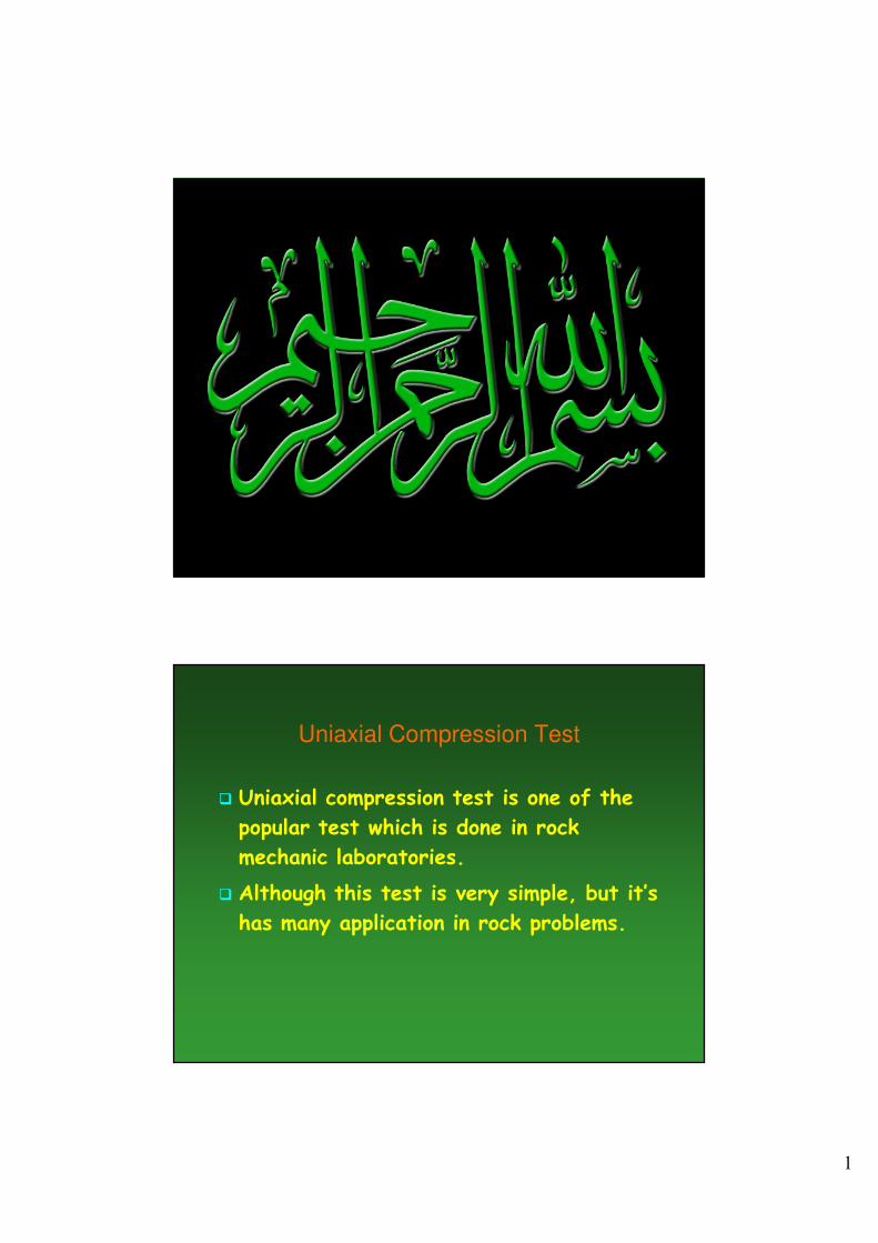
Effective parameter on UCS
� Internal parameters
� mineralogy
� density
� porosity
� shape and size of minerals
� anisotropy
� External parameters
� effect of loading places
� size of sample
� shape (geometry) of sample
� water
� rate of loading
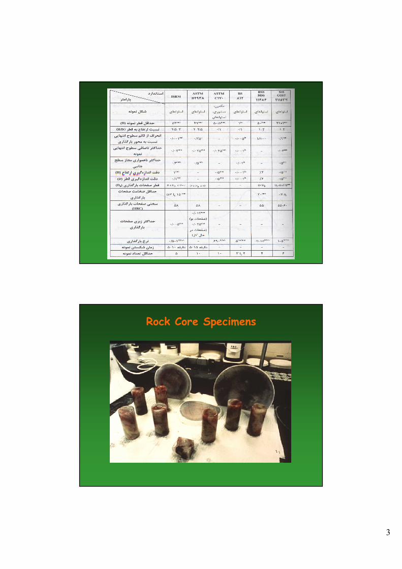
Uniaxial Compressive Strength
� Standard index property (qu = σσσσu = σσσσc)
� Analogous tests in concrete and soil (unconfined compression test).
� ASTM 4543.
� ISRM 1979, Suggested methods for determining the uniaxial compressive strength and deformability of rock materials. Int J Rock Mech Min Sci Geomech Abs 16(2), sid 135-140.
� ISRM 1999, Draft ISRM suggested method for the complete stress-strain curve for intact rock in uniaxial compression. Int J Rock Mech Min Sci 36(3), sid 279-289.
� Planar ends on NQ size core (d = 47.6 mm)
� Length-to-width ratio: 2 < H/d < 2.5
� Axial loading of cylindrical core specimen
� σσσσu = Max. Force/(ππππd2/4)
3
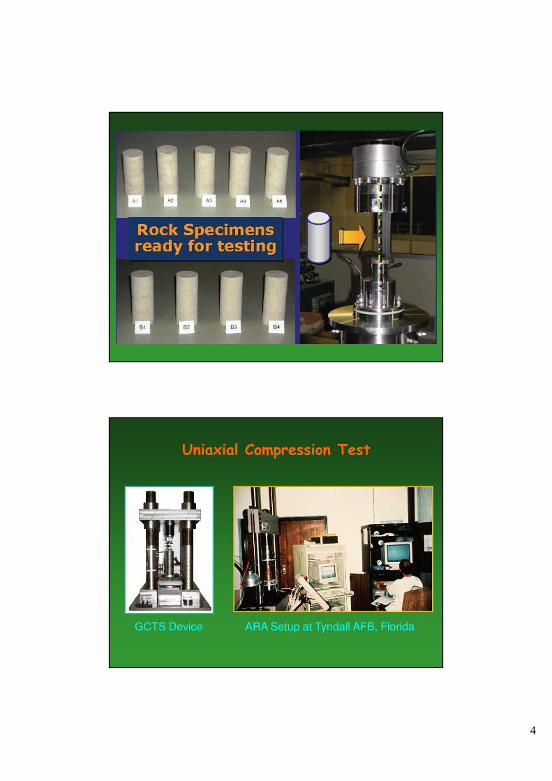
Rock Core Specimens
4
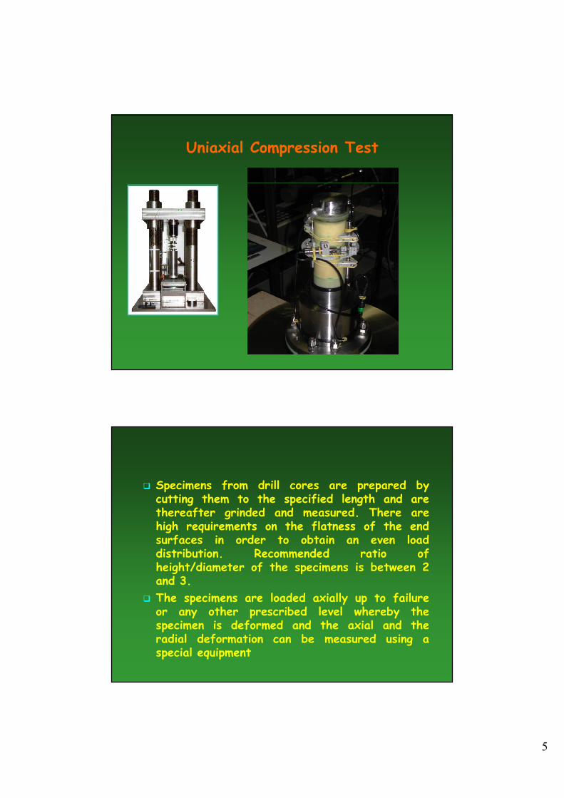
Uniaxial Compression Test
GCTS Device ARA Setup at Tyndall AFB, Florida
5
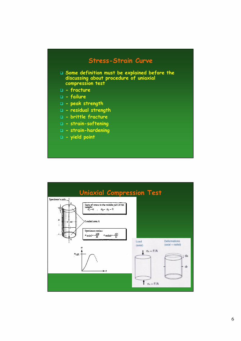
Uniaxial Compression Test
� Specimens from drill cores are prepared bycutting them to the specified length and arethereafter grinded and measured. There arehigh requirements on the flatness of the endsurfaces in order to obtain an even loaddistribution. Recommended ratio ofheight/diameter of the specimens is between 2and 3.
� The specimens are loaded axially up to failureor any other prescribed level whereby thespecimen is deformed and the axial and theradial deformation can be measured using aspecial equipment
6
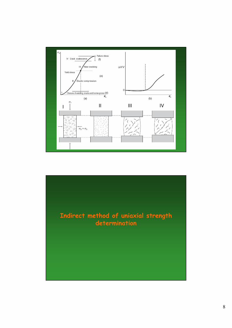
Stress-Strain Curve
� Some definition must be explained before the discussing about procedure of uniaxial compression test
� - fracture
� - failure
� - peak strength
� - residual strength
� - brittle fracture
� - strain-softening
� - strain-hardening
� - yield point
Uniaxial Compression Test
7
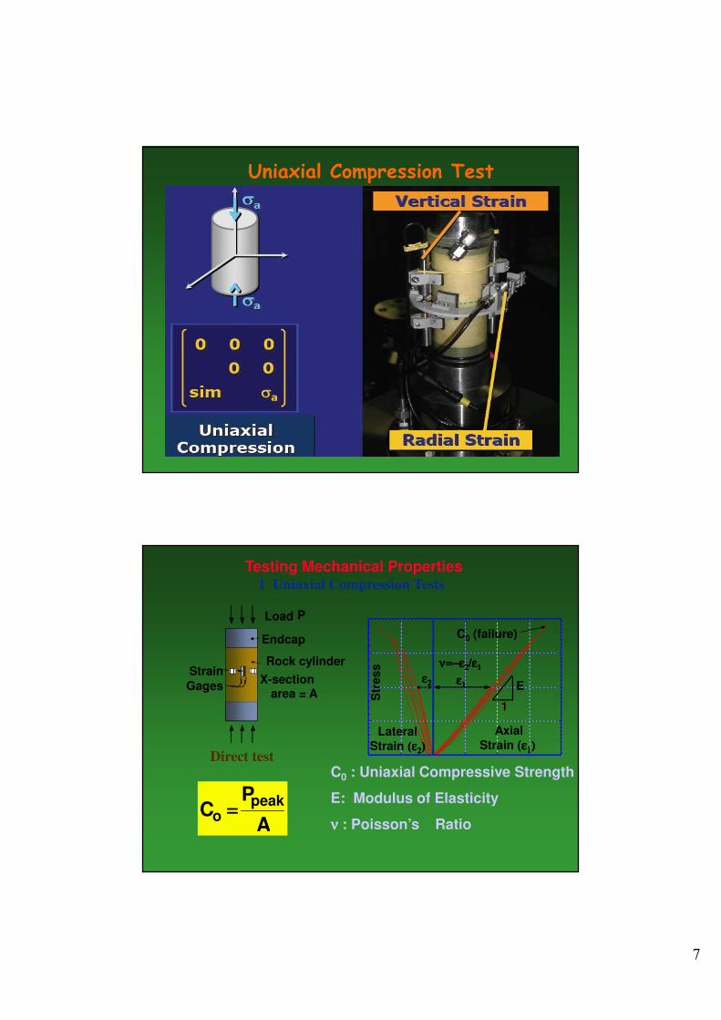
Uniaxial Compression Test
Testing Mechanical Properties1 Uniaxial Compression Tests
Direct test
Load P
Rock cylinder
X-section area = A
Endcap
Strain
Gages E
1
Str
ess
Axial
Strain (εεεε1111))))
Lateral
Strain (ε(ε(ε(ε2222))))
εεεε1111εεεε2222
ν=ν=ν=ν=−−−−εεεε2222/ε/ε/ε/ε1111
1
C0 (failure)
C0 : Uniaxial Compressive Strength
E: Modulus of Elasticity
νννν : Poisson’s RatioA
PC
peako ====
8
I II III IV
Indirect method of uniaxial strength determination
9
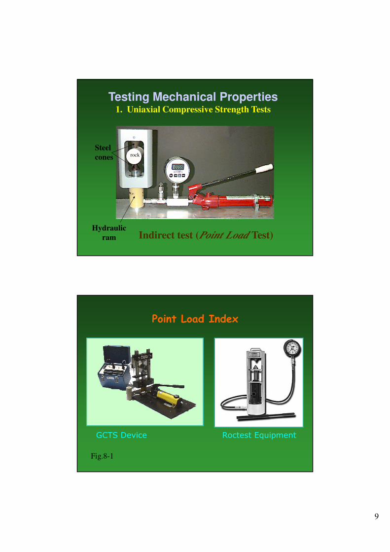
Indirect test (Point Load Test)
Steel
cones rock
Hydraulic
ram
Testing Mechanical Properties1. Uniaxial Compressive Strength Tests
Point Load Index
GCTS Device Roctest Equipment
Fig.8-1
10
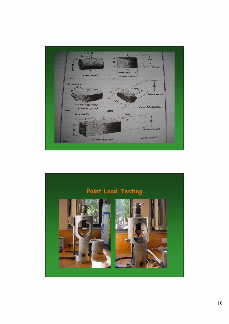
Point Load Testing
11
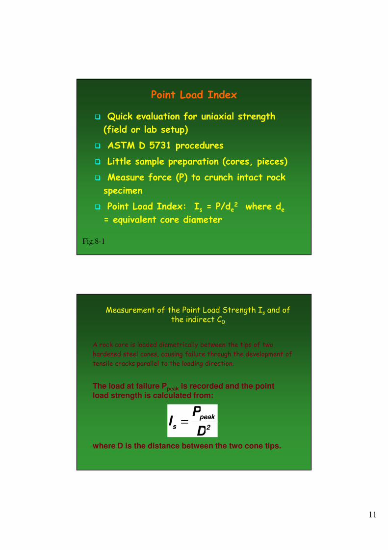
Point Load Index
� Quick evaluation for uniaxial strength
(field or lab setup)
� ASTM D 5731 procedures
� Little sample preparation (cores, pieces)
� Measure force (P) to crunch intact rock
specimen
� Point Load Index: Is = P/de2 where de= equivalent core diameter
Fig.8-1
Measurement of the Point Load Strength Is and of the indirect C0
A rock core is loaded diametrically between the tips of two
hardened steel cones, causing failure through the development of
tensile cracks parallel to the loading direction.
2
peak
sD
PI =
The load at failure Ppeak is recorded and the point load strength is calculated from:
where D is the distance between the two cone tips.
12
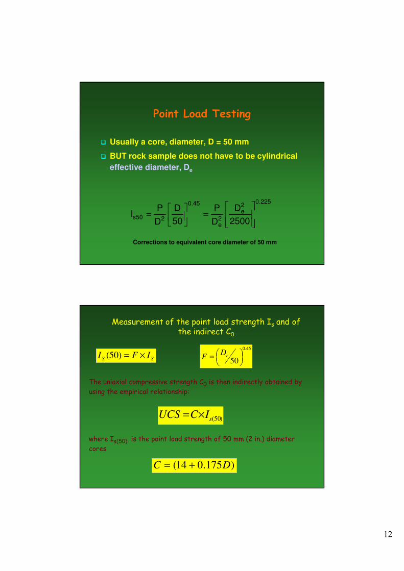
Point Load Testing
� Usually a core, diameter, D = 50 mm
� BUT rock sample does not have to be cylindrical
effective diameter, De
225.02e
2e
45.0
250s2500
D
D
P
50
D
D
PI
=
=
Corrections to equivalent core diameter of 50 mm
Measurement of the point load strength Is and of the indirect C0
The uniaxial compressive strength C0 is then indirectly obtained by
using the empirical relationship:
where Is(50) is the point load strength of 50 mm (2 in.) diameter
cores
)50(sICUCS ×=
SSIFI ×=)50(
45.0
50
= e
DF
)175.014( DC +=
13
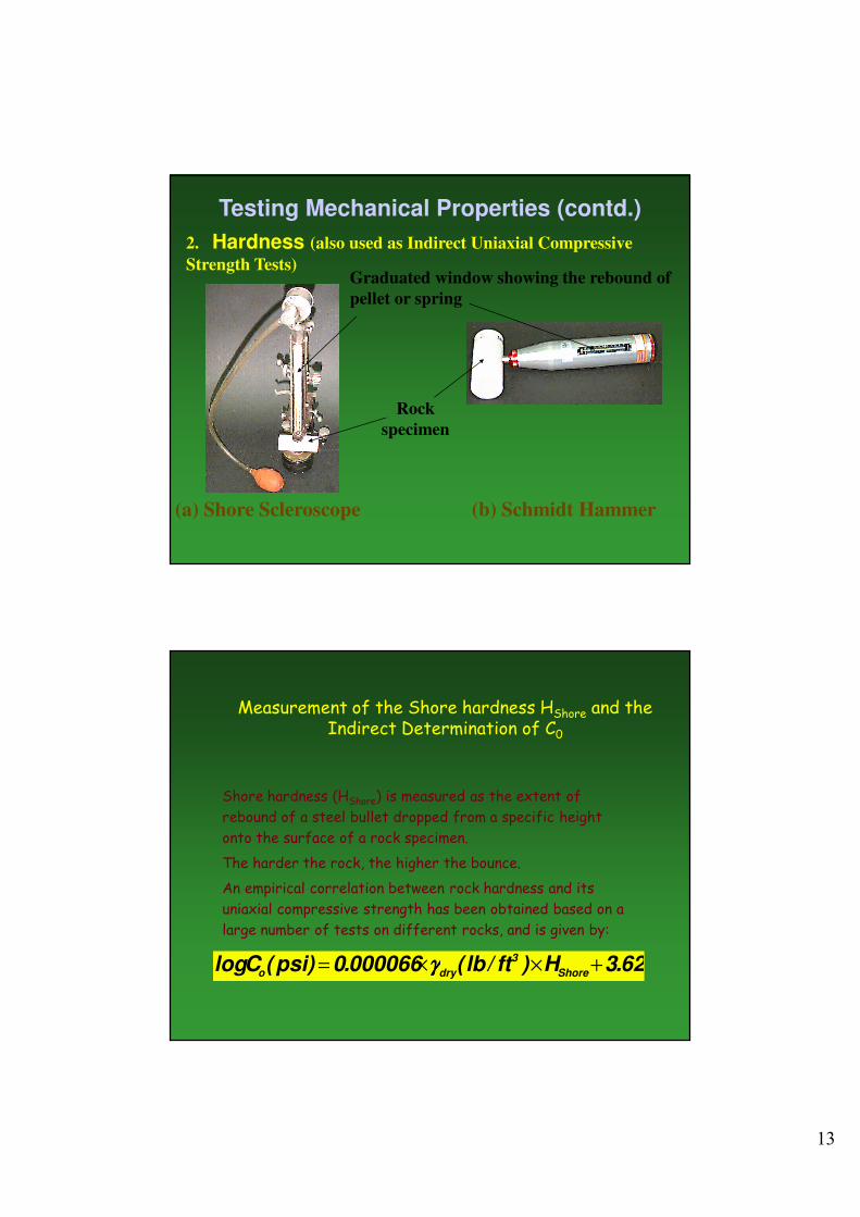
Testing Mechanical Properties (contd.)
2. Hardness (also used as Indirect Uniaxial Compressive
Strength Tests)
(a) Shore Scleroscope (b) Schmidt Hammer
Rock
specimen
Graduated window showing the rebound of
pellet or spring
Measurement of the Shore hardness HShore and the Indirect Determination of C0
Shore hardness (HShore) is measured as the extent of
rebound of a steel bullet dropped from a specific height
onto the surface of a rock specimen.
The harder the rock, the higher the bounce.
An empirical correlation between rock hardness and its
uniaxial compressive strength has been obtained based on a
large number of tests on different rocks, and is given by:
62.3H)ft/lb(000066.0)psi(ClogShore
3
dryo+××= γγγγ
14
Measurement of the Schmidt hardness HSmdt, and the Indirect Determination of C0
The Schmidt Hammer is a portable tool, similar in principle to the
Shore Scleroscope. It is used exclusively for rock and rock-like
materials and is easy of use in the field. It measures the
rebound off the surface of rock of a spring-driven steel pellet.
An empirical correlation between the Schmidt rock hardness and
uniaxial compressive strength has been obtained based on a large
number of tests on different rocks:
16.3H)ft/lb(00014.0)psi(ClogSmdt
3
dry0+××= γγγγ
( )[ ]wS
HUCS
γ×+×=
0087.016.0109.6
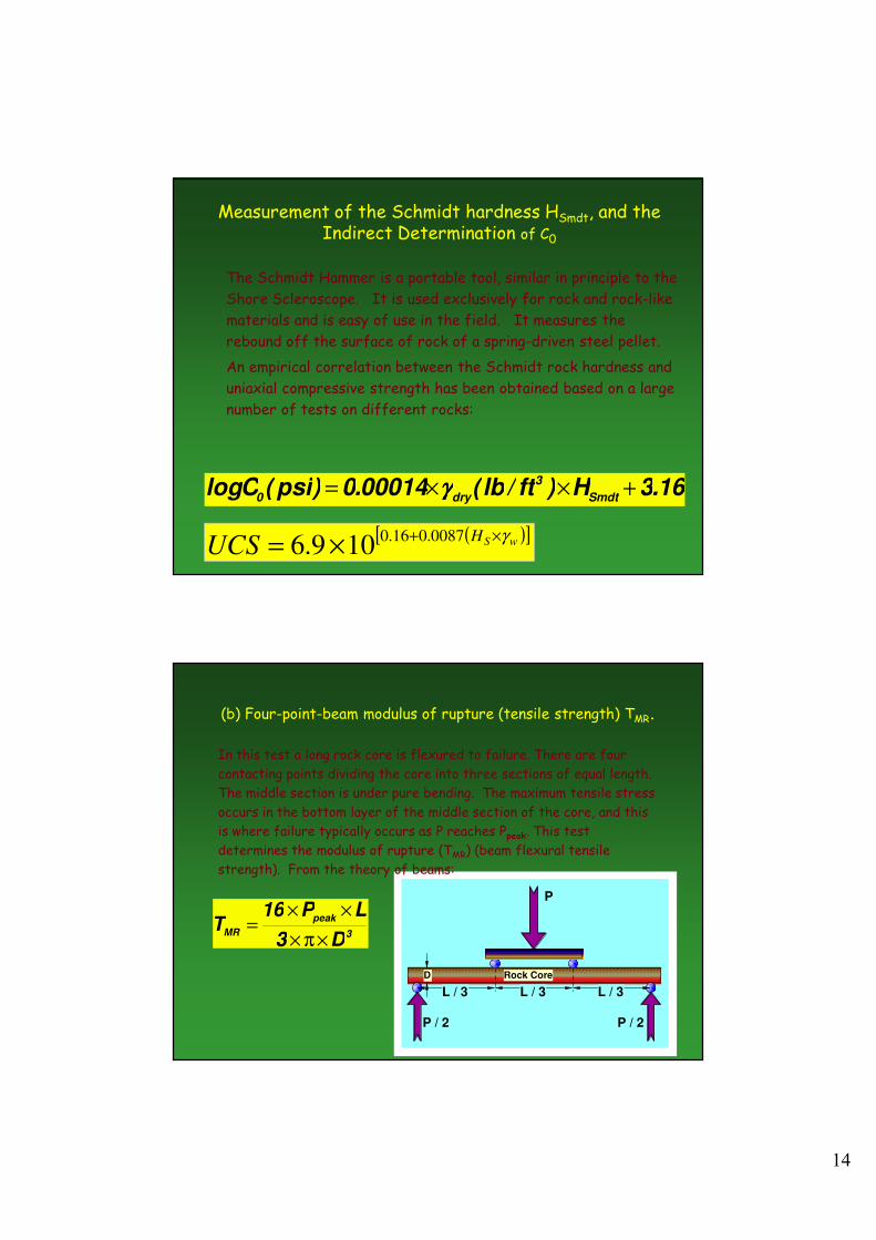
L / 3 L / 3 L / 3
P
P / 2 P / 2
D Rock Core
3
peak
MRD3
LP16T
×π×
××=
(b) Four-point-beam modulus of rupture (tensile strength) TMR.
In this test a long rock core is flexured to failure. There are four
contacting points dividing the core into three sections of equal length.
The middle section is under pure bending. The maximum tensile stress
occurs in the bottom layer of the middle section of the core, and this
is where failure typically occurs as P reaches Ppeak. This test
determines the modulus of rupture (TMR) (beam flexural tensile
strength). From the theory of beams:
15
Tensile strength
� Direct method
� Indirect method
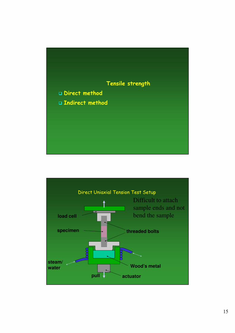
Direct Uniaxial Tension Test Setup
steam/water
actuator
Wood’s metal
pull
load cell
specimen threaded bolts
Difficult to attach
sample ends and not
bend the sample
16
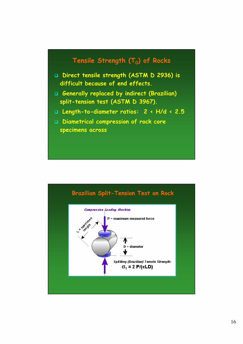
Tensile Strength (T0) of Rocks
� Direct tensile strength (ASTM D 2936) is
difficult because of end effects.
� Generally replaced by indirect (Brazilian)
split-tension test (ASTM D 3967).
� Length-to-diameter ratios: 2 < H/d < 2.5
� Diametrical compression of rock core
specimens across
Brazilian Split-Tension Test on Rock
17
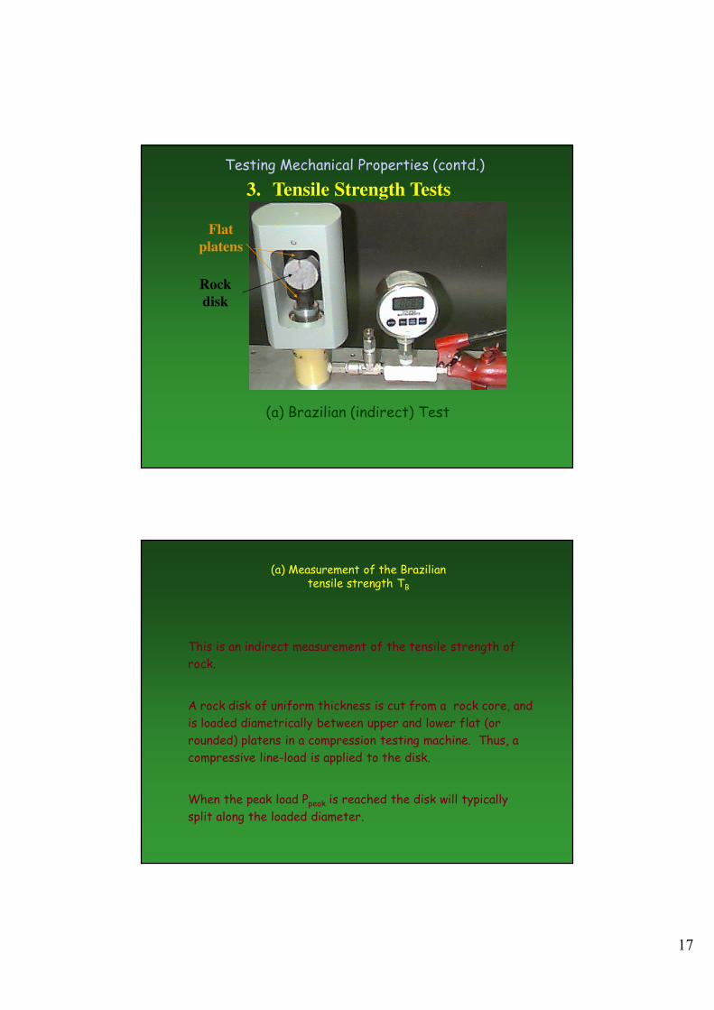
Testing Mechanical Properties (contd.)
3. Tensile Strength Tests
(a) Brazilian (indirect) Test
Flat
platens
Rock
disk
(a) Measurement of the Brazilian tensile strength TB
This is an indirect measurement of the tensile strength of
rock.
A rock disk of uniform thickness is cut from a rock core, and
is loaded diametrically between upper and lower flat (or
rounded) platens in a compression testing machine. Thus, a
compressive line-load is applied to the disk.
When the peak load Ppeak is reached the disk will typically
split along the loaded diameter.
18
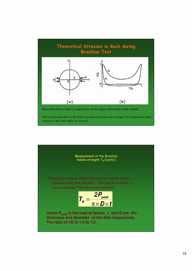
Theoretical Stresses in Rock during Brazilian Test
Stress Parallel to load is compressive at the edges and tensile in the middle.
Stress perpendicular to the load is greater but rocks are stronger in compression than
tension so the rock splits in tension.
Measurement of the Brazilian tensile strength TB (contd.)
Theoretical analysis shows that uniform tensile stress
develops along this diameter. The tensile strength TB
can be obtained from the elastic solution:
tD
P2T peak
B××π
=
where Ppeak is the load at failure, t and D are the thickness and diameter of the disk respectively.
The ratio of t/D is 1/4 to 1/2.
19
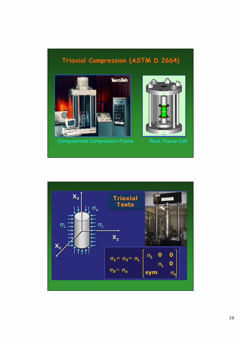
Triaxial Compression (ASTM D 2664)
Computerized Compression Frame Rock Triaxial Cell
20
21
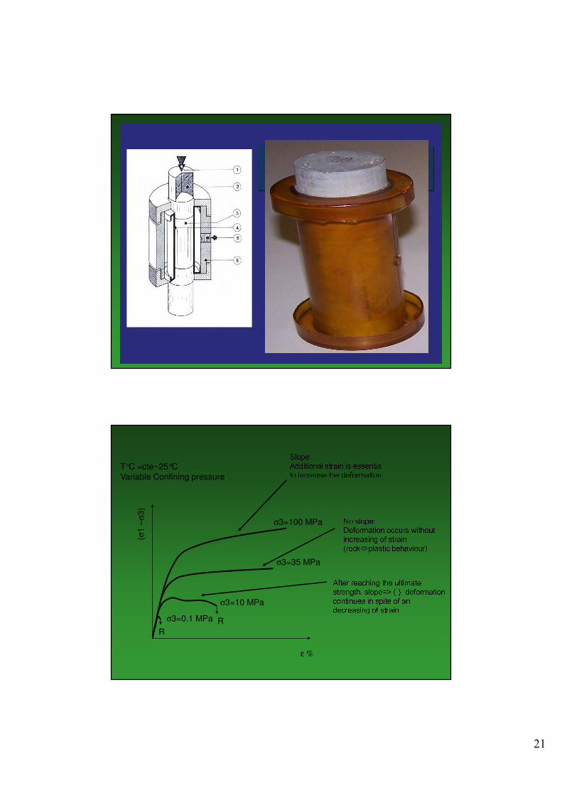
σ3=100 MPa
T°C =cte~25°C
Variable Confining pressure
Slope:Additional strain is essential to increase the deformation
(σ1
–σ
3)
ε %
σ3=35 MPa
σ3=10 MPa
σ3=0.1 MPa
R
R
No slope:Deformation occurs without increasing of strain (rock�plastic behaviour)After reaching the ultimate strength, slope=> (-), deformation continues in spite of an decreasing of strain
22
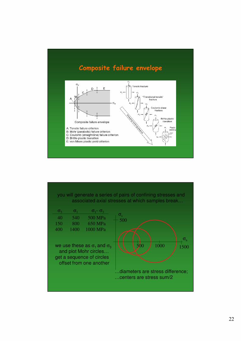
Composite failure envelope
you will generate a series of pairs of confining stresses and
associated axial stresses at which samples break…
40 540 500 MPa
150 800 650 MPa
400 1400 1000 MPa
σ1σ3
we use these as σ1 and σ3
and plot Mohr circles…
get a sequence of circles
offset from one another
σ1- σ3σs
σn
500
500
1000 1500
…diameters are stress difference;
…centers are stress sum/2