Embed Size (px)
Citation preview

Unicasts, Multicasts and Broadcasts
Part 1: Frame-Based LAN Operation
V1.0: Geoff Bennett

LANs as a Shared MediumLANs as a Shared Medium
A "Private" ConversationA "Private" Conversation
Multicast AddressingMulticast Addressing
Performance IssuesPerformance Issues
In this tutorial I'll explain the operation of address recognition on a conventional LAN, and highlight the implications of this mode of operation when we move to a connection-oriented ATM network.
To move directly to one of these sections, click on the relevant rectangle with the mouse. Otherwise, continue to the next slide.
ContentsContents

In this section I'll describe the way that shared LAN technologies operate with respect to frame addressing and recognition.
LANs as a Shared MediumLANs as a Shared Medium
A "Private" ConversationA "Private" Conversation
Multicast AddressingMulticast Addressing
Performance IssuesPerformance Issues
ContentsContents
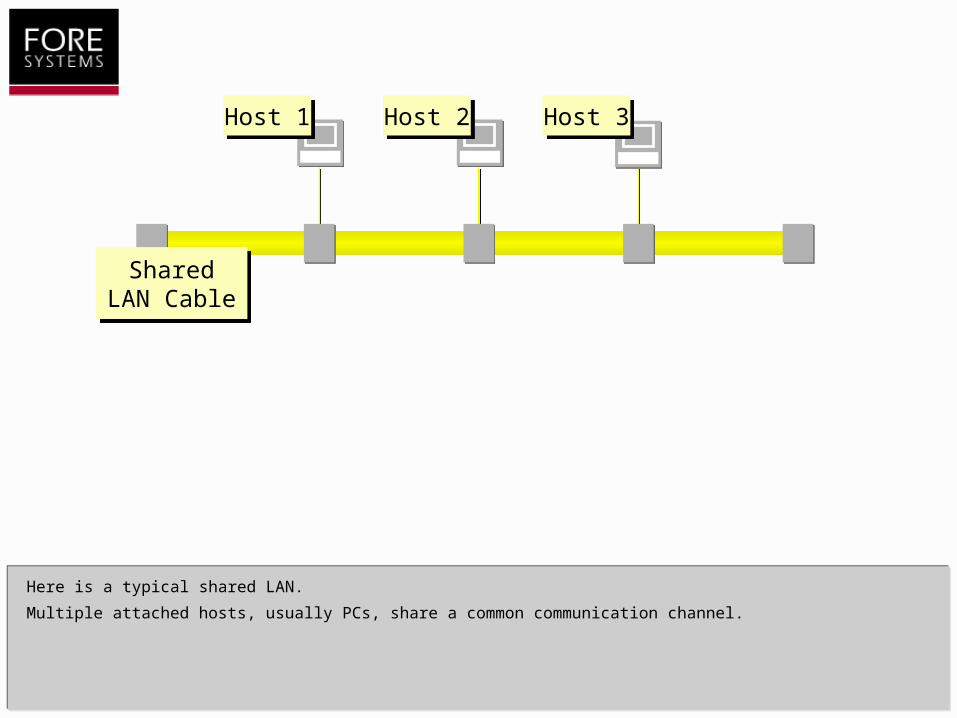
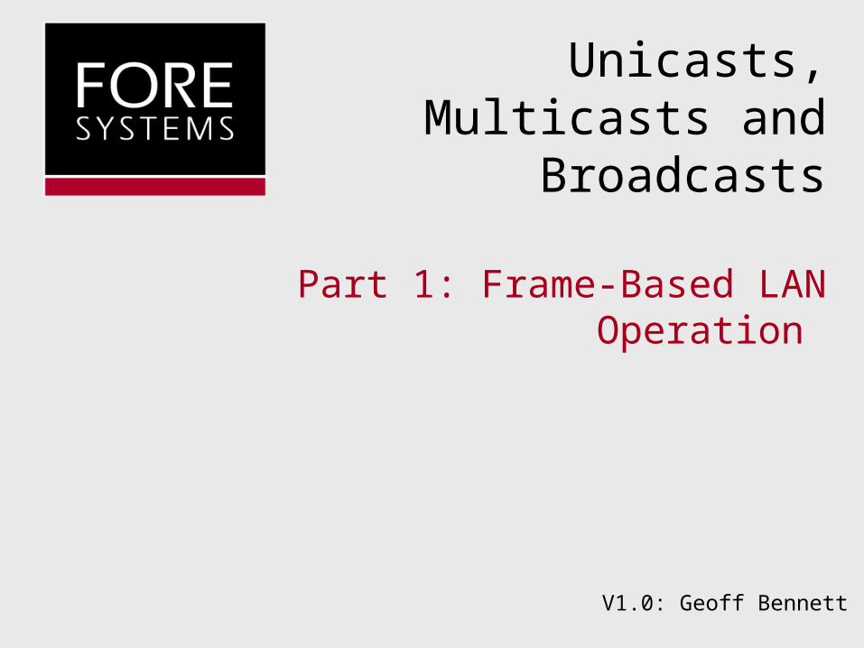
Here is a typical shared LAN.
Multiple attached hosts, usually PCs, share a common communication channel.
Host 1Host 1 Host 2Host 2 Host 3Host 3
Shared LAN Cable
Shared LAN Cable
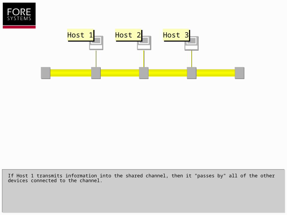
If Host 1 transmits information into the shared channel, then it "passes by" all of the other devices connected to the channel.
Host 1Host 1 Host 2Host 2 Host 3Host 3

Host 2Host 2 Host 3Host 3
If Host 1 transmits information into the shared channel, then it "passes by" all of the other devices connected to the channel.
Host 1Host 1
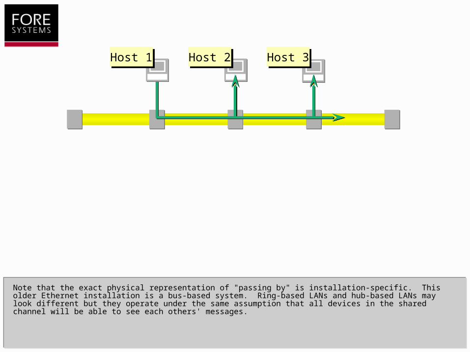
Note that the exact physical representation of "passing by" is installation-specific. This older Ethernet installation is a bus-based system. Ring-based LANs and hub-based LANs may look different but they operate under the same assumption that all devices in the shared channel will be able to see each others' messages.
Host 2Host 2 Host 3Host 3Host 1Host 1
Host 2Host 2 Host 3Host 3Host 1Host 1
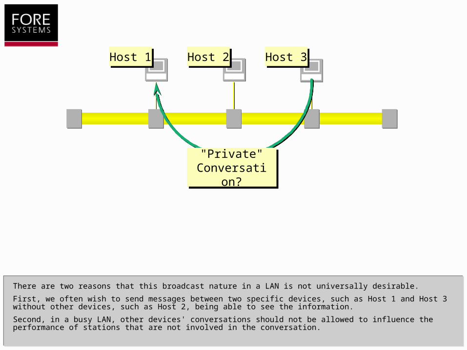
There are two reasons that this broadcast nature in a LAN is not universally desirable.
First, we often wish to send messages between two specific devices, such as Host 1 and Host 3 without other devices, such as Host 2, being able to see the information.
Second, in a busy LAN, other devices' conversations should not be allowed to influence the performance of stations that are not involved in the conversation.
"Private" Conversation
?
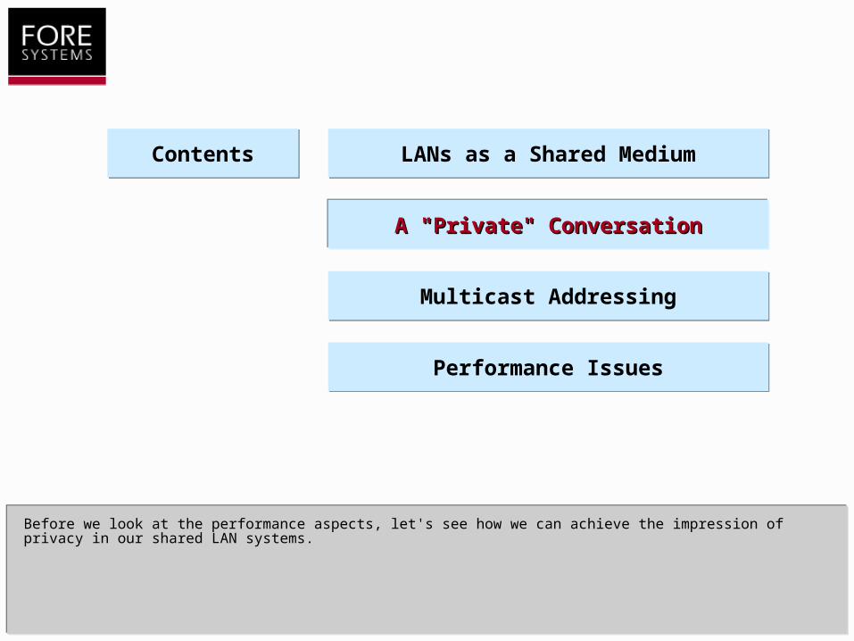
Before we look at the performance aspects, let's see how we can achieve the impression of privacy in our shared LAN systems.
LANs as a Shared MediumLANs as a Shared Medium
A "Private" ConversationA "Private" Conversation
Multicast AddressingMulticast Addressing
Performance IssuesPerformance Issues
ContentsContents
Host 1Host 1 Host 2Host 2 Host 3Host 3
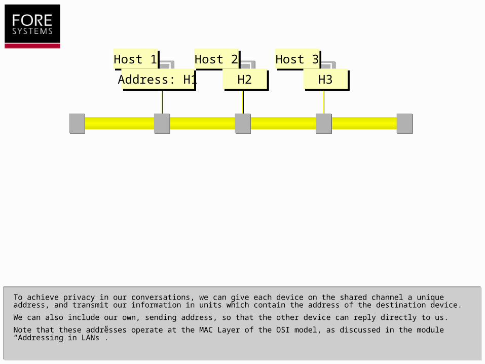
To achieve privacy in our conversations, we can give each device on the shared channel a unique address, and transmit our information in units which contain the address of the destination device.
We can also include our own, sending address, so that the other device can reply directly to us.
Note that these addresses operate at the MAC Layer of the OSI model, as discussed in the module “Addressing in LANs”.
Address: H1 H2 H3
Host 1Host 1 Host 2Host 2 Host 3Host 3
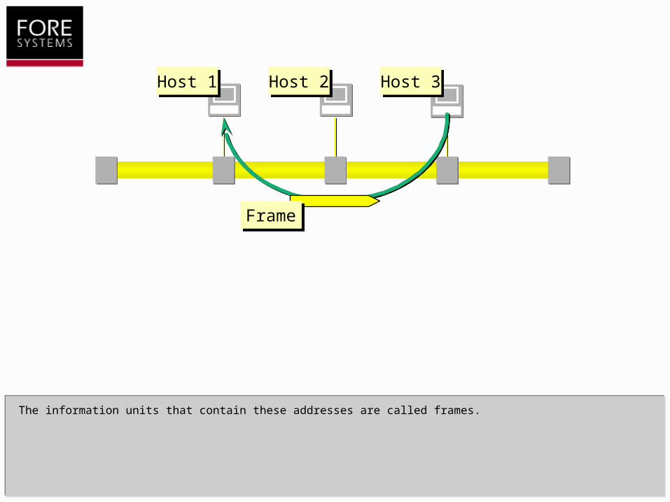
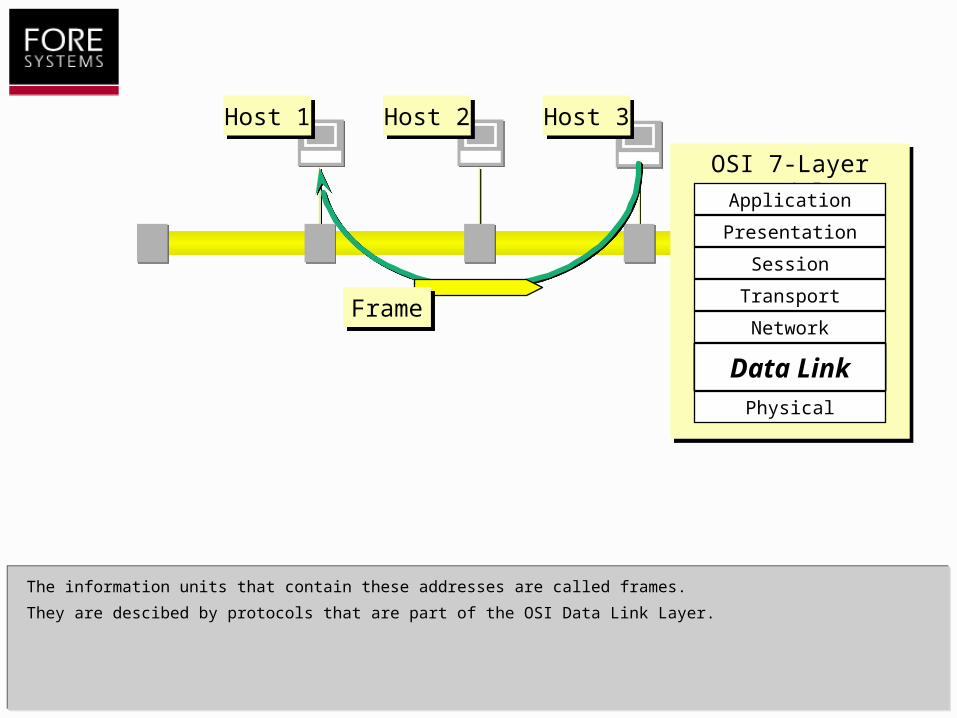
The information units that contain these addresses are called frames.
FrameFrame
The information units that contain these addresses are called frames.
They are descibed by protocols that are part of the OSI Data Link Layer.
FrameFrame
OSI 7-Layer ModelOSI 7-Layer Model
Data Link
Physical
Network
Transport
Session
Presentation
Application
Data LinkData LinkData Link
Host 1Host 1 Host 2Host 2 Host 3Host 3
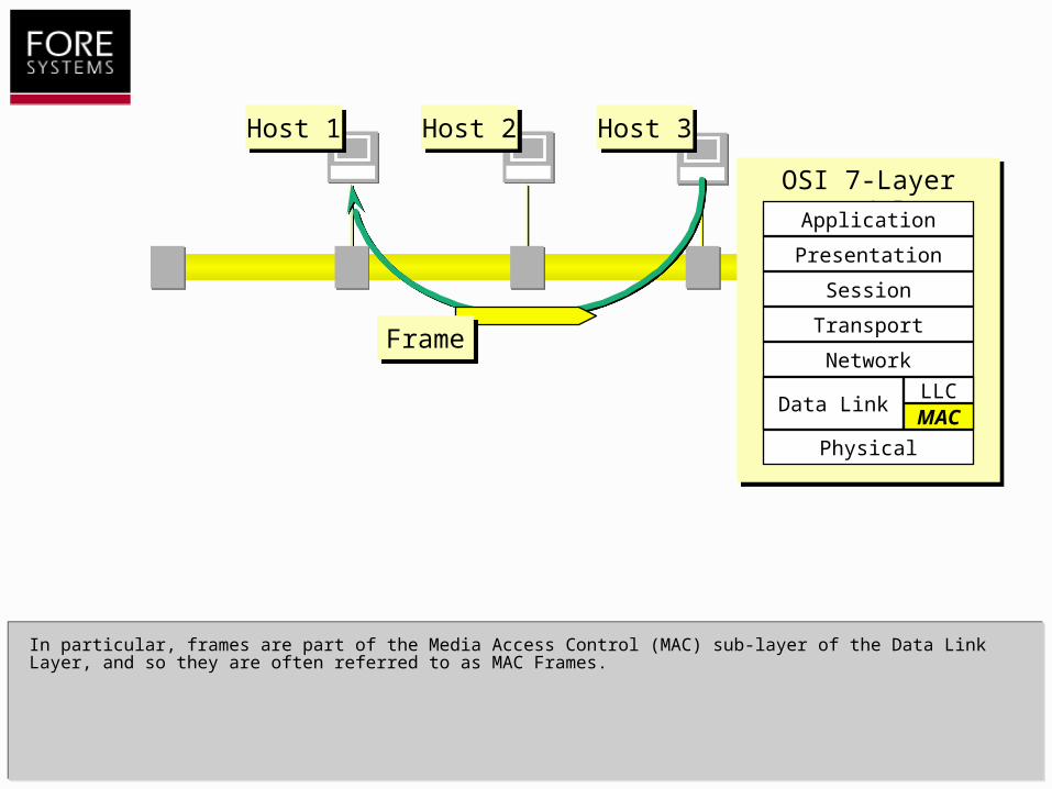
In particular, frames are part of the Media Access Control (MAC) sub-layer of the Data Link Layer, and so they are often referred to as MAC Frames.
FrameFrame
Host 1Host 1 Host 2Host 2 Host 3Host 3
OSI 7-Layer ModelOSI 7-Layer Model
Physical
Network
Transport
Session
Presentation
Application
Data LinkMACLLC
Data Link
Host 1Host 1 Host 2Host 2 Host 3Host 3
OSI 7-Layer ModelOSI 7-Layer Model
Physical
Network
Transport
Session
Presentation
Application
Data LinkMACLLC
Data Link
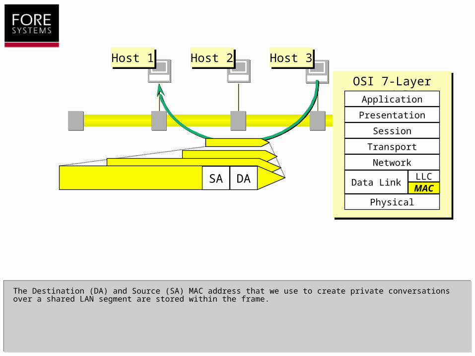
The Destination (DA) and Source (SA) MAC address that we use to create private conversations over a shared LAN segment are stored within the frame.
DASA
Host 1Host 1 Host 2Host 2 Host 3Host 3
OSI 7-Layer ModelOSI 7-Layer Model
Physical
Network
Transport
Session
Presentation
Application
Data LinkMACLLC
Data LinkDASA
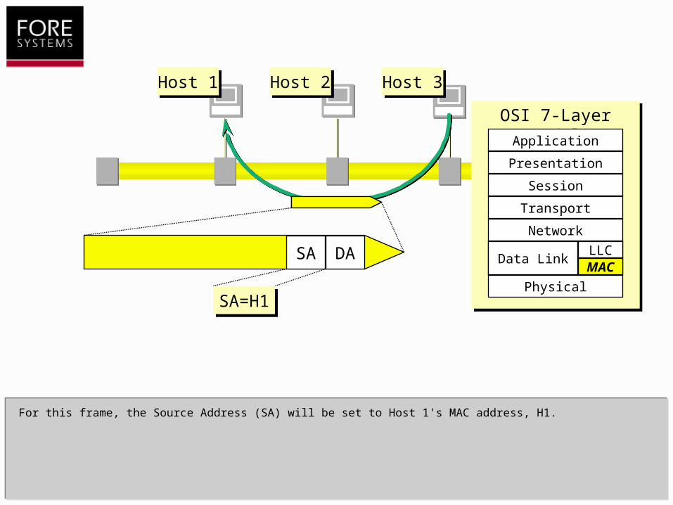
For this frame, the Source Address (SA) will be set to Host 1's MAC address, H1.
SA=H1SA=H1

Host 1Host 1 Host 2Host 2 Host 3Host 3
OSI 7-Layer ModelOSI 7-Layer Model
Physical
Network
Transport
Session
Presentation
Application
Data LinkMACLLC
Data LinkDASA
SA=H1SA=H1
For this frame, the Source Address (SA) will be set to Host 1's MAC address, H1.
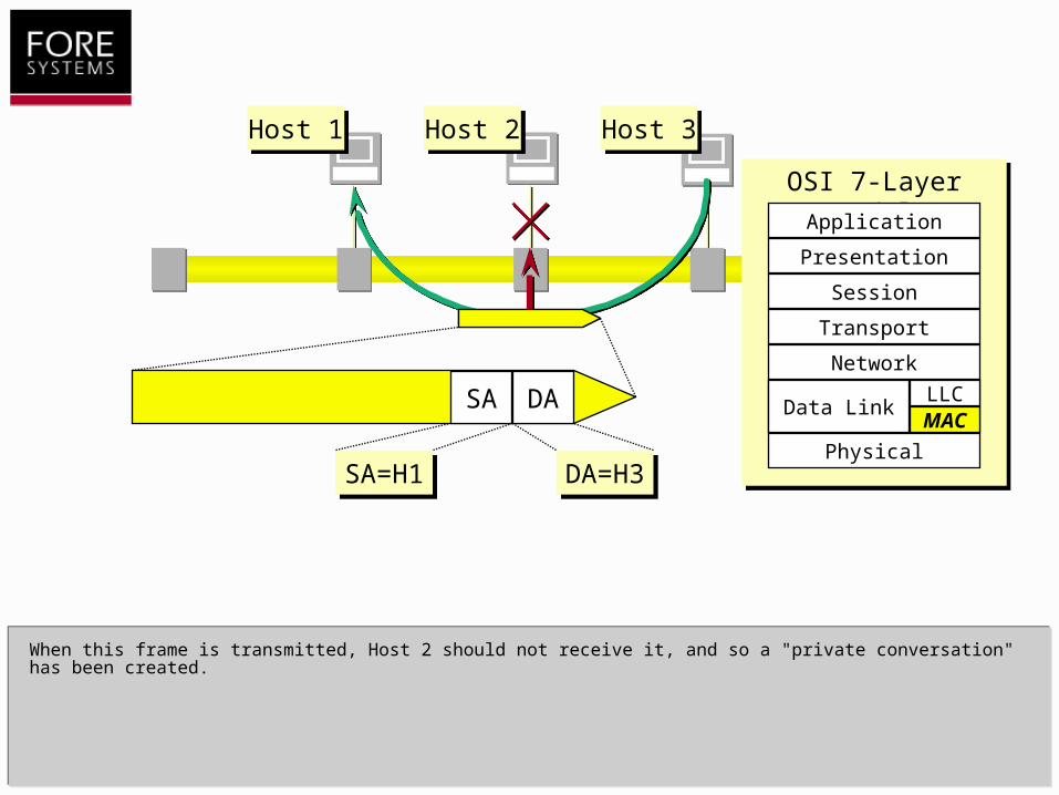
The Destination Address (DA) is set to Host 3's MAC address, H3.
DA=H3DA=H3
Host 1Host 1 Host 2Host 2 Host 3Host 3
OSI 7-Layer ModelOSI 7-Layer Model
Physical
Network
Transport
Session
Presentation
Application
Data LinkMACLLC
Data LinkDASA
SA=H1SA=H1
When this frame is transmitted, Host 2 should not receive it, and so a "private conversation" has been created.
DA=H3DA=H3
Host 1Host 1 Host 2Host 2 Host 3Host 3
OSI 7-Layer ModelOSI 7-Layer Model
Physical
Network
Transport
Session
Presentation
Application
Data LinkMACLLC
Data LinkDASA
SA=H1SA=H1
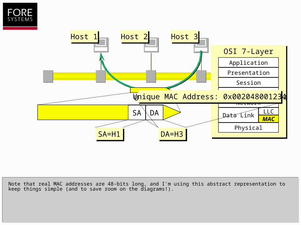
Note that real MAC addresses are 48-bits long, and I'm using this abstract representation to keep things simple (and to save room on the diagrams!).
DA=H3DA=H3
Unique MAC Address: 0x002048001234Unique MAC Address: 0x002048001234
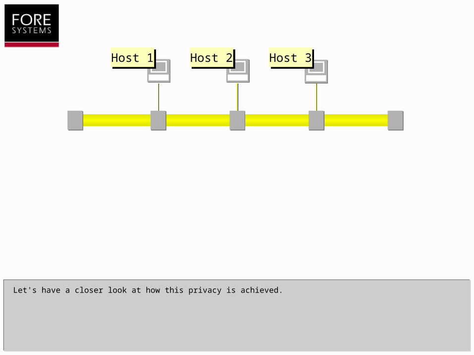
Let's have a closer look at how this privacy is achieved.
Host 1Host 1 Host 2Host 2 Host 3Host 3

Let's have a closer look at how this privacy is achieved.
I'm going to zoom in on Host 3.
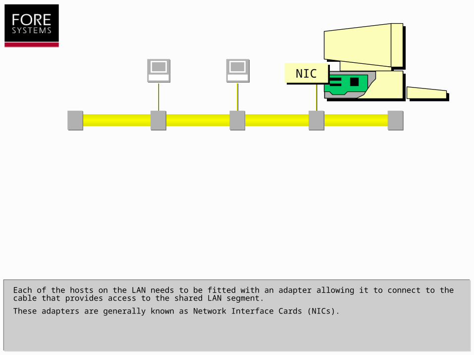
Each of the hosts on the LAN needs to be fitted with an adapter allowing it to connect to the cable that provides access to the shared LAN segment.
These adapters are generally known as Network Interface Cards (NICs).
NIC

NIC
Inside each NIC there is the unique, 48-bit MAC address to which this adapter will respond. This address is called the Unicast Address of the NIC.
The response is controlled by high-speed address recognition circuits that are implemented in hardware on the NIC.
These circuits are capable of scanning the bitstream at full wire speed for any Destination Address on a frame that matches the NIC's unique, unicast address.
Unique MAC Address: 0x002048001234Unique MAC Address: 0x002048001234
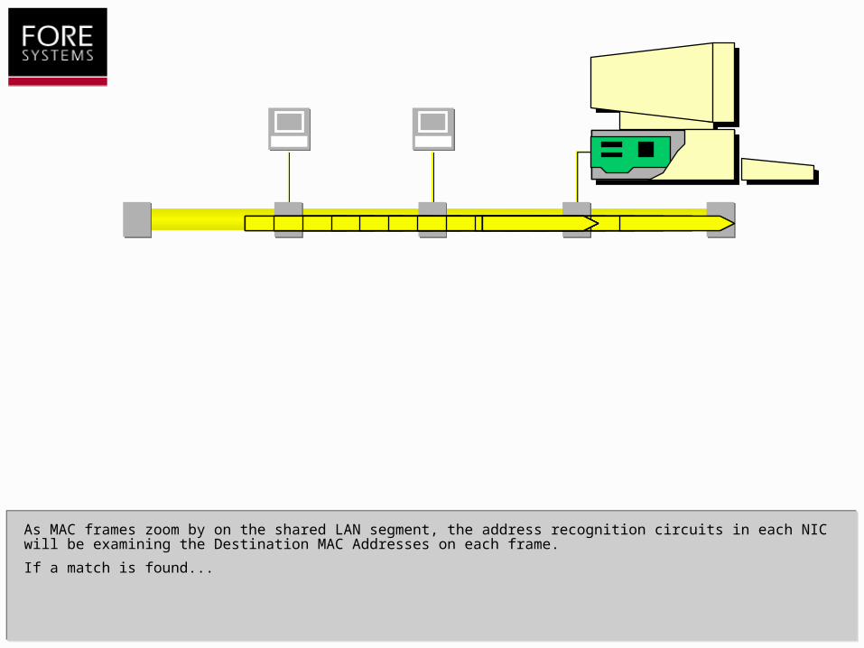
As MAC frames zoom by on the shared LAN segment, the address recognition circuits in each NIC will be examining the Destination MAC Addresses on each frame.
If a match is found...

…then the entire MAC frame will be copied into the receive buffer on the NIC.
Note that the term copy implies that the "original" frame that was recognised is allowed to continue along the LAN segment.
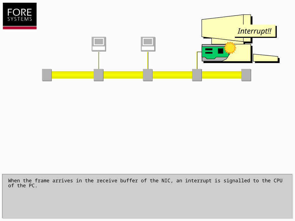
When the frame arrives in the receive buffer of the NIC, an interrupt is signalled to the CPU of the PC.
Interrupt!!Interrupt!!
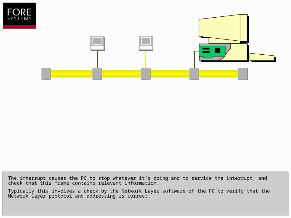
The interrupt causes the PC to stop whatever it's doing and to service the interrupt, and check that this frame contains relevant information.
Typically this involves a check by the Network Layer software of the PC to verify that the Network Layer protocol and addressing is correct.
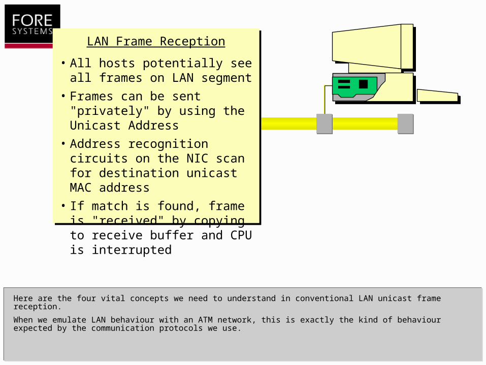
Here are the four vital concepts we need to understand in conventional LAN unicast frame reception.
When we emulate LAN behaviour with an ATM network, this is exactly the kind of behaviour expected by the communication protocols we use.
LAN Frame Reception
• All hosts potentially see all frames on LAN segment
• Frames can be sent "privately" by using the Unicast Address
• Address recognition circuits on the NIC scan for destination unicast MAC address
• If match is found, frame is "received" by copying to receive buffer and CPU is interrupted

So far I've discussed the idea of a private conversation on a LAN segment using unicast addressing.
In this next section I'll discuss another address type called multicasts, which are used to transmit the same piece of information to more than one device on the network.
LANs as a Shared MediumLANs as a Shared Medium
A "Private" ConversationA "Private" Conversation
Multicast AddressingMulticast Addressing
Performance IssuesPerformance Issues
ContentsContents

Suppose we have a slightly larger population of hosts on our LAN segment...
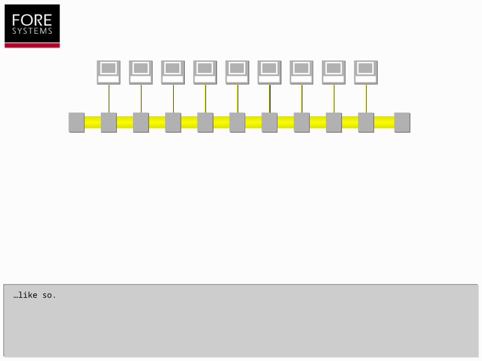
…like so.

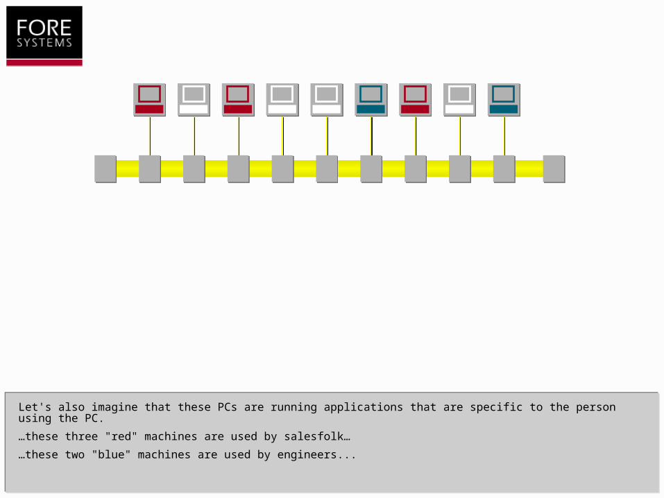
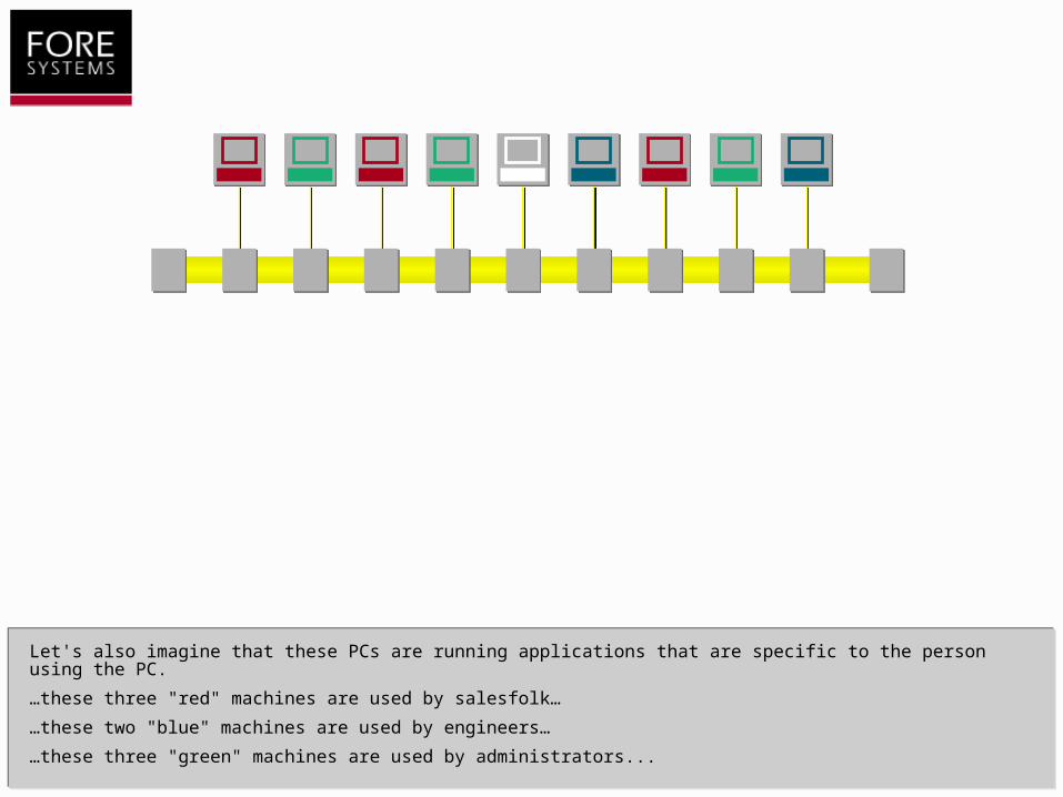
Let's also imagine that these PCs are running applications that are specific to the person using the PC.

Let's also imagine that these PCs are running applications that are specific to the person using the PC.
…these three "red" machines are used by salesfolk.
Let's also imagine that these PCs are running applications that are specific to the person using the PC.
…these three "red" machines are used by salesfolk…
…these two "blue" machines are used by engineers...
Let's also imagine that these PCs are running applications that are specific to the person using the PC.
…these three "red" machines are used by salesfolk…
…these two "blue" machines are used by engineers…
…these three "green" machines are used by administrators...
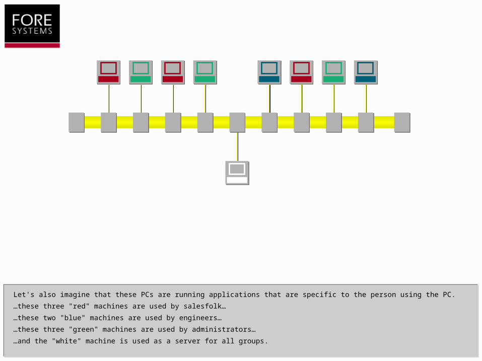
Let's also imagine that these PCs are running applications that are specific to the person using the PC.
…these three "red" machines are used by salesfolk…
…these two "blue" machines are used by engineers…
…these three "green" machines are used by administrators…
…and the "white" machine is used as a server for all groups.
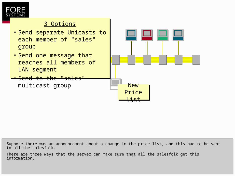
Suppose there was an announcement about a change in the price list, and this had to be sent to all the salesfolk.
There are three ways that the server can make sure that all the salesfolk get this information.
New Price List
New Price List
3 Options
• Send separate Unicasts to each member of "sales" group
• Send one message that reaches all members of LAN segment
• Send to the "sales" multicast group

The first method requires the server to send an explicit unicast message to each member of the Sales group in turn.
Remember that each member of the LAN segment has a unique, unicast address.
Each frame sent will be received by only one member of the group because it is addressed to the unicast destination for that member.
New Price List
New Price List
H1
H9
H2
H8
H5
H7
H3
H4
H6

New Price List
New Price List
H1
H9
H2
H8
H5
H7
H3
H4
H6
In order to send frames to the sales group (the red PCs, remember), the server will need a list of unicast MAC addresses belonging to the sales group...
Option 1: Multiple Unicast Messages to Group Members
Group Membership
• Sales: H1, H2, H7Sales: H1, H2, H7
• Engineering: H5, H4
• Admin: H9, H8, H3

New Price List
New Price List
H1
H9
H2
H8
H5
H7
H3
H4
H6
Group Membership
• Sales: H1, H2, H7
• Engineering: H5, H4
• Admin: H9, H8, H3
The server can now send one or more frames that represent the message about the new Price List to each member in turn. Note the number of frames sent by the server will be equal to the number of members in the group multiplied by the number of frames in the complete message.
So, for example, a message made up of a thousand frames (about 1MByte) sent to three group members will consist of three thousand individual frame transmissions. As the number of group members increases, so does the work done by the server.
Option 1: Multiple Unicast Messages to Group Members
New Price List
New Price List
H1
H9
H2
H8
H5
H7
H3
H4
H6
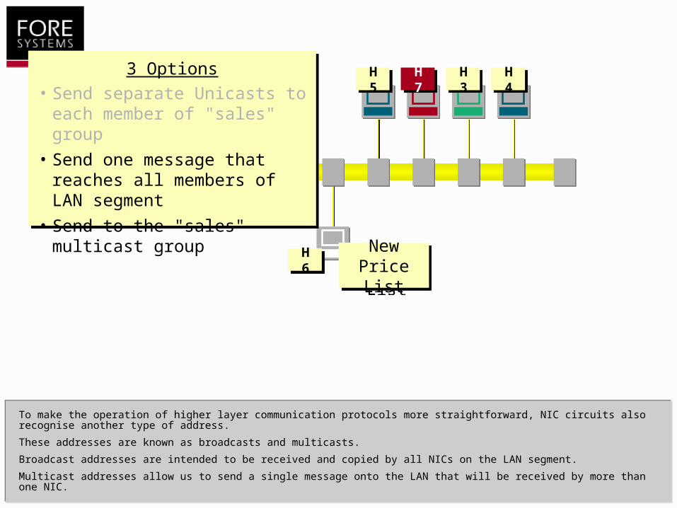
To make the operation of higher layer communication protocols more straightforward, NIC circuits also recognise another type of address.
These addresses are known as broadcasts and multicasts.
Broadcast addresses are intended to be received and copied by all NICs on the LAN segment.
Multicast addresses allow us to send a single message onto the LAN that will be received by more than one NIC.
3 Options
• Send separate Unicasts to each member of "sales" group
• Send one message that reaches all members of LAN segment
• Send to the "sales" multicast group

Let's take a closer look at the NIC.
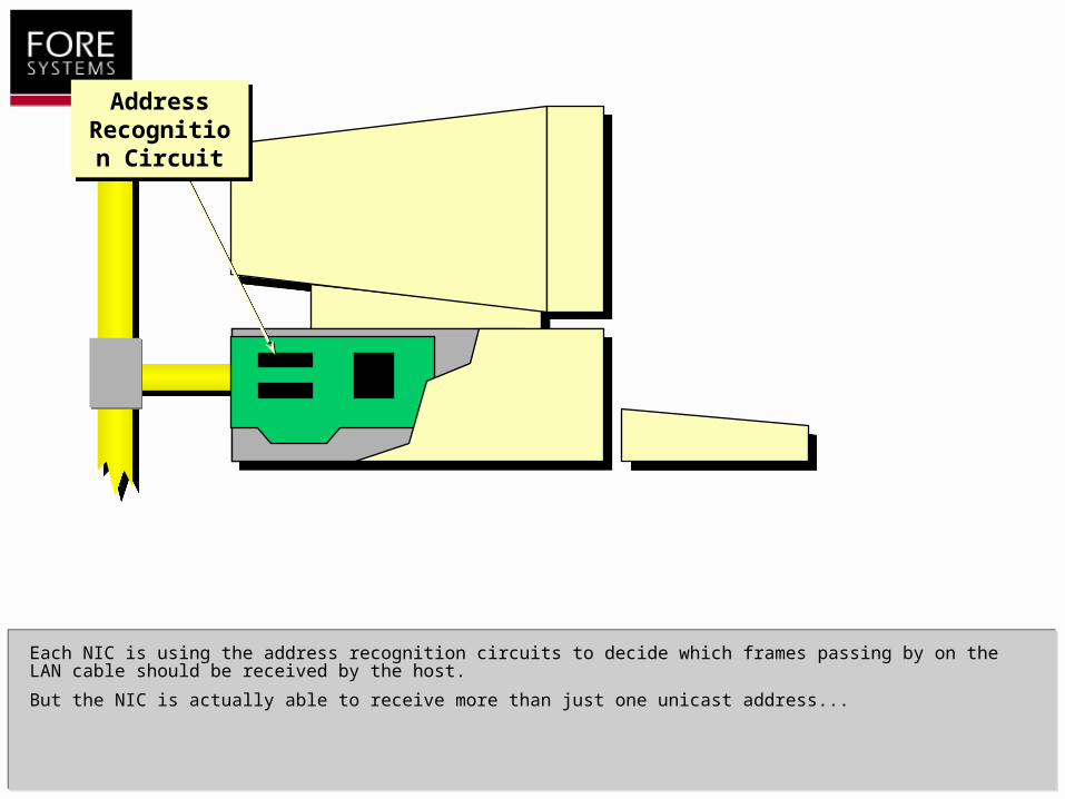
Each NIC is using the address recognition circuits to decide which frames passing by on the LAN cable should be received by the host.
But the NIC is actually able to receive more than just one unicast address...
Address Recognition
Circuit
Address Recognition
Circuit

The unicast address I've described so far is usually known as the burned-in address because it is permanently stored inside a component on the NIC.
The manufacturer of the NIC is assigned a unique block of MAC addresses, and is responsible for allocating unique unicast addresses within this block to each NIC it produces.
Addresses I RecogniseAddresses I Recognise
1. Burned-in unicast address
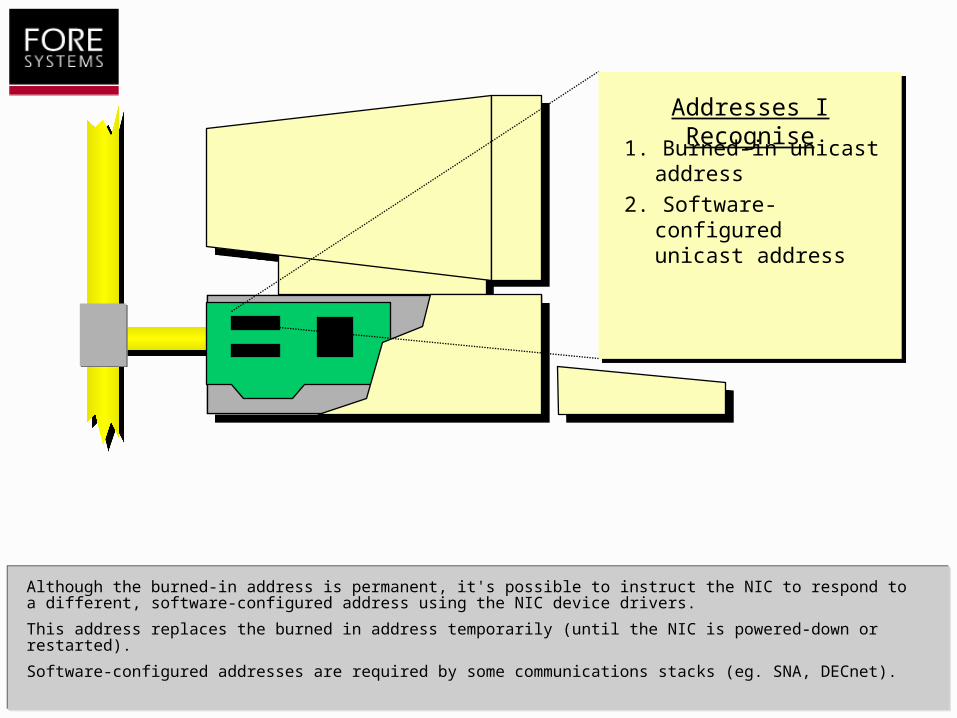
Although the burned-in address is permanent, it's possible to instruct the NIC to respond to a different, software-configured address using the NIC device drivers.
This address replaces the burned in address temporarily (until the NIC is powered-down or restarted).
Software-configured addresses are required by some communications stacks (eg. SNA, DECnet).
Addresses I RecogniseAddresses I Recognise
1. Burned-in unicast address
2. Software-configured unicast address

Addresses I RecogniseAddresses I Recognise
The NIC may also be software-configured with a small number (usually 8) multicast addresses.
1. Burned-in unicast address
2. Software-configured unicast address
3. One or more multicast addresses

Finally, all NICs should respond to a special form of multicast address known as the broadcast address.
A broadcast message is intended to be received and copied by all hosts that are on the LAN segment.
Many older communication protocols make use of broadcasts to discover hosts on the LAN, or to advertise services to LAN clients.
Addresses I RecogniseAddresses I Recognise
1. Burned-in unicast address
2. Software-configured unicast address
3. One or more multicast addresses
4. The broadcast address
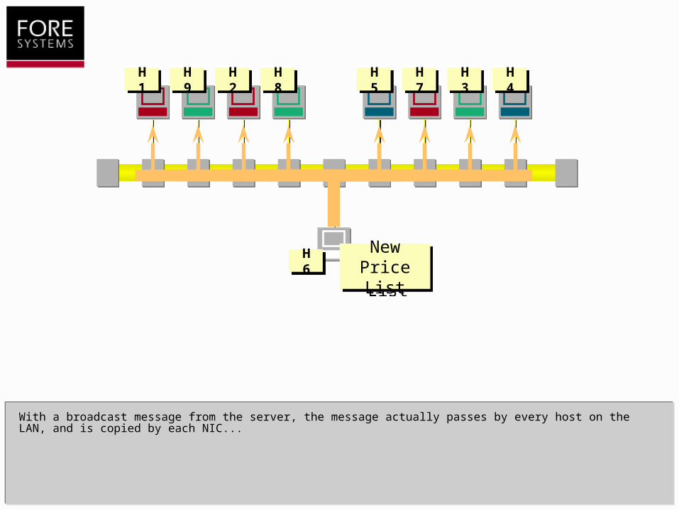
With a broadcast message from the server, the message actually passes by every host on the LAN, and is copied by each NIC...
New Price List
New Price List
H1
H9
H2
H8
H5
H7
H3
H4
H6
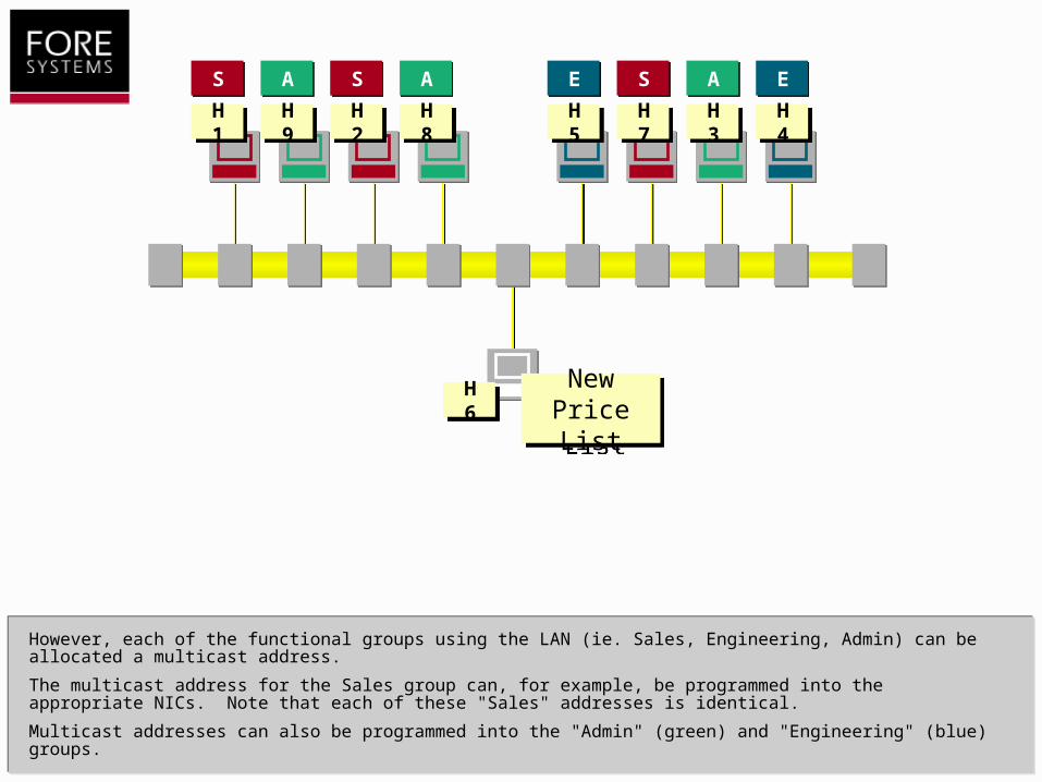
However, each of the functional groups using the LAN (ie. Sales, Engineering, Admin) can be allocated a multicast address.
The multicast address for the Sales group can, for example, be programmed into the appropriate NICs. Note that each of these "Sales" addresses is identical.
Multicast addresses can also be programmed into the "Admin" (green) and "Engineering" (blue) groups.
S S SA A AE E
New Price List
New Price List
H1
H9
H2
H8
H5
H7
H3
H4
H6

H1
H9
H2
H8
H5
H7
H3
H4
As long as the server knows the "Sales" multicast address, then it can send out frames with this multicast address.
These frames will only be received by NICs that are programmed with the multicast address.
Protocol stacks such as TCP/IP include a dynamic host multicast registration protocol (IGMP for TCP/IP).
SS SS SS
New Price List
New Price List
H6
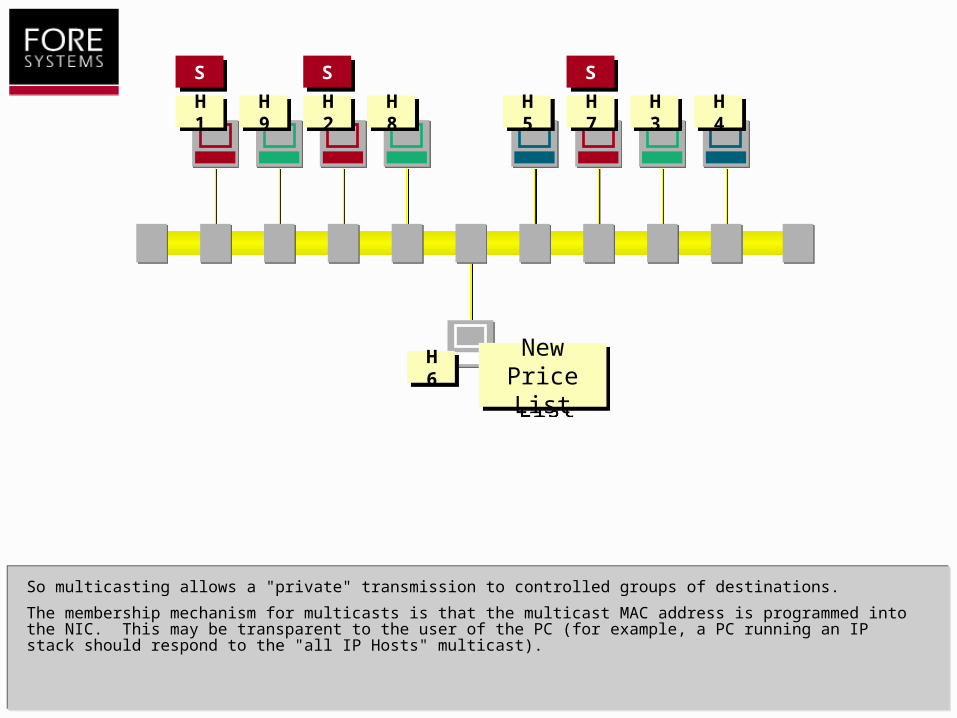
So multicasting allows a "private" transmission to controlled groups of destinations.
The membership mechanism for multicasts is that the multicast MAC address is programmed into the NIC. This may be transparent to the user of the PC (for example, a PC running an IP stack should respond to the "all IP Hosts" multicast).
H1
H9
H2
H8
H5
H7
H3
H4
SS SS SS
New Price List
New Price List
H6

A PC can belong to multiple multicast groups, as well as responding to its unicast address.
As I mentioned earlier, a typical Ethernet adapter can be programmed with up to 8 multicast addresses.
Addresses I RecogniseAddresses I Recognise
1. My unicast address
2. All-IP Hosts multicast
3. One or more application
multicast addresses
4. The broadcast address
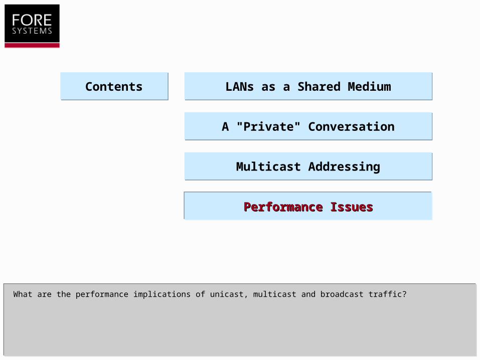
What are the performance implications of unicast, multicast and broadcast traffic?
LANs as a Shared MediumLANs as a Shared Medium
A "Private" ConversationA "Private" Conversation
Multicast AddressingMulticast Addressing
Performance IssuesPerformance Issues
ContentsContents
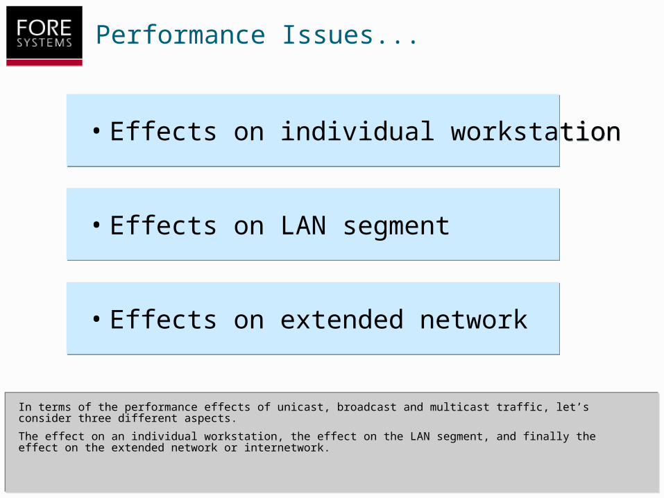
Performance Issues...
In terms of the performance effects of unicast, broadcast and multicast traffic, let’s consider three different aspects.
The effect on an individual workstation, the effect on the LAN segment, and finally the effect on the extended network or internetwork.
• Effects on individual workstation• Effects on individual workstation
• Effects on LAN segment• Effects on LAN segment
• Effects on extended network• Effects on extended network
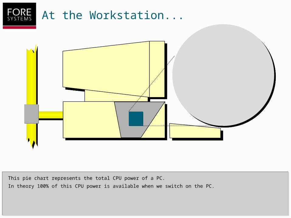
This pie chart represents the total CPU power of a PC.
In theory 100% of this CPU power is available when we switch on the PC.
At the Workstation...

Some percentage of the CPU power is taken up by "housekeeping" duties, represented by the grey portion of the pie.
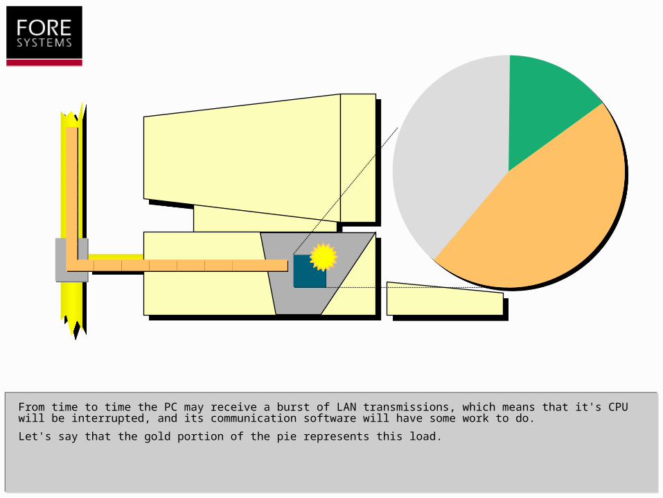
From time to time the PC may receive a burst of LAN transmissions, which means that it's CPU will be interrupted, and its communication software will have some work to do.
Let's say that the gold portion of the pie represents this load.
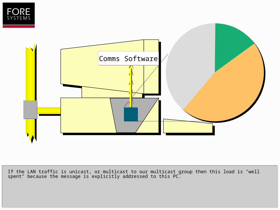
If the LAN traffic is unicast, or multicast to our multicast group then this load is "well spent" because the message is explicitly addressed to this PC.
Comms SoftwareComms SoftwareComms SoftwareComms SoftwareComms SoftwareComms Software
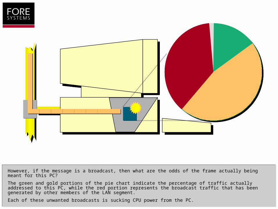
However, if the message is a broadcast, then what are the odds of the frame actually being meant for this PC?
The green and gold portions of the pie chart indicate the percentage of traffic actually addressed to this PC, while the red portion represents the broadcast traffic that has been generated by other members of the LAN segment.
Each of these unwanted broadcasts is sucking CPU power from the PC.
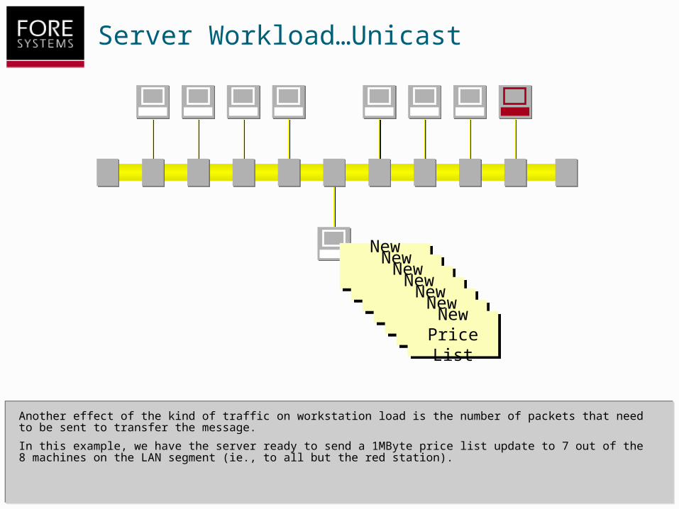
Server Workload…Unicast
Another effect of the kind of traffic on workstation load is the number of packets that need to be sent to transfer the message.
In this example, we have the server ready to send a 1MByte price list update to 7 out of the 8 machines on the LAN segment (ie., to all but the red station).
New Price List
New Price List
New Price List
New Price List
New Price List
New Price List
New Price List
New Price List
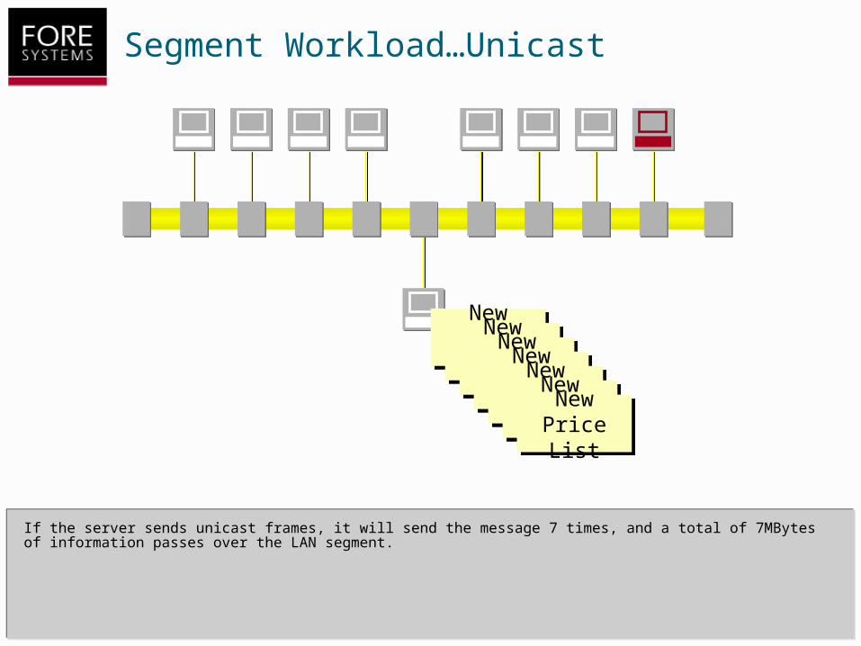
Segment Workload…Unicast
If the server sends unicast frames, it will send the message 7 times, and a total of 7MBytes of information passes over the LAN segment.
New Price List
New Price List
New Price List
New Price List
New Price List
New Price List
New Price List
New Price List

WAN Workload…Unicast
If the LAN segment is connected to the rest of the world through a router, unicasts to the 7 workstations will never “leak” onto the bandwidth-restricted WAN.
“Rest of the
World”
“Rest of the
World”
New Price List
New Price List
New Price List
New Price List
New Price List
New Price List
New Price List
New Price List

WAN Workload…Unicast
But if there is another set of workstations across the WAN that need to receive the price list update, then an additional copy of the message will have to be sent for each workstation.
Clearly the multiple unicast mechanism is not a scalable approach.
New Price List
New Price List
“Rest of the
World”
“Rest of the
World”

Server Workload…Broadcast
For a broadcast message the server sends only one copy...
New Price List
New Price List

Server Workload…Broadcast
For a broadcast message the server sends only one copy…
…but as I mentioned earlier, every station on the LAN segment will copy the message. At best this places a CPU interrupt burden on the red workstation, at worst it poses a security issue.
New Price List
New Price List
I got it too!
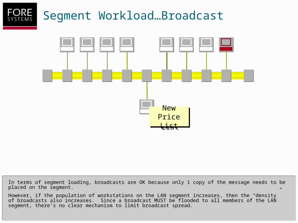
Segment Workload…Broadcast
In terms of segment loading, broadcasts are OK because only 1 copy of the message needs to be placed on the segment.
However, if the population of workstations on the LAN segment increases, then the “density” of broadcasts also increases. Since a broadcast MUST be flooded to all members of the LAN segment, there’s no clear mechanism to limit broadcast spread.
New Price List
New Price List
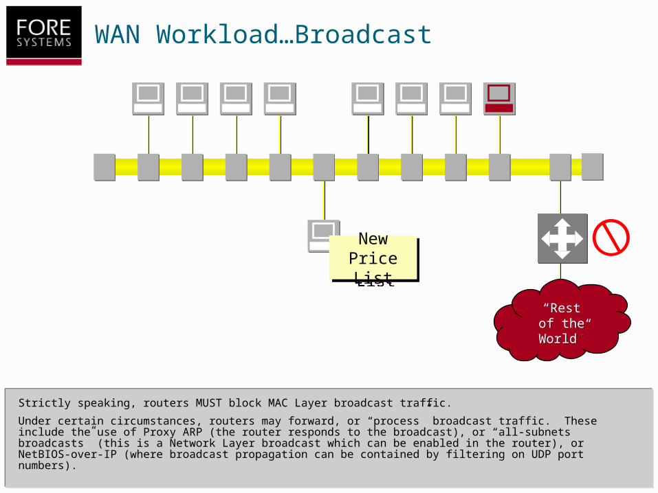
WAN Workload…Broadcast
Strictly speaking, routers MUST block MAC Layer broadcast traffic.
Under certain circumstances, routers may forward, or “process” broadcast traffic. These include the use of Proxy ARP (the router responds to the broadcast), or “all-subnets broadcasts” (this is a Network Layer broadcast which can be enabled in the router), or NetBIOS-over-IP (where broadcast propagation can be contained by filtering on UDP port numbers).
“Rest of the
World”
“Rest of the
World”
New Price List
New Price List
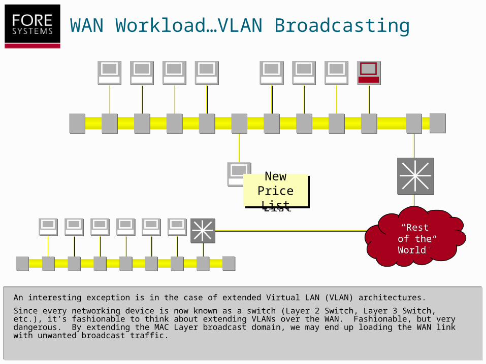
WAN Workload…VLAN Broadcasting
An interesting exception is in the case of extended Virtual LAN (VLAN) architectures.
Since every networking device is now known as a switch (Layer 2 Switch, Layer 3 Switch, etc.), it’s fashionable to think about extending VLANs over the WAN. Fashionable, but very dangerous. By extending the MAC Layer broadcast domain, we may end up loading the WAN link with unwanted broadcast traffic.
New Price List
New Price List
“Rest of the
World”
“Rest of the
World”
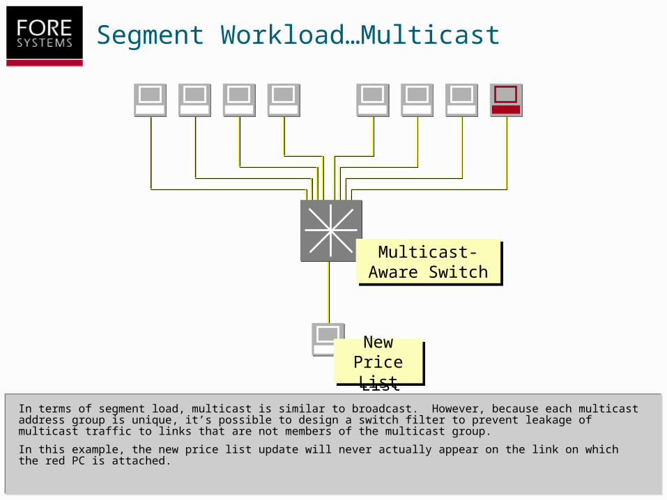
Segment Workload…Multicast
New Price List
New Price List
In terms of segment load, multicast is similar to broadcast. However, because each multicast address group is unique, it’s possible to design a switch filter to prevent leakage of multicast traffic to links that are not members of the multicast group.
In this example, the new price list update will never actually appear on the link on which the red PC is attached.
Multicast-Aware Switch
Multicast-Aware Switch
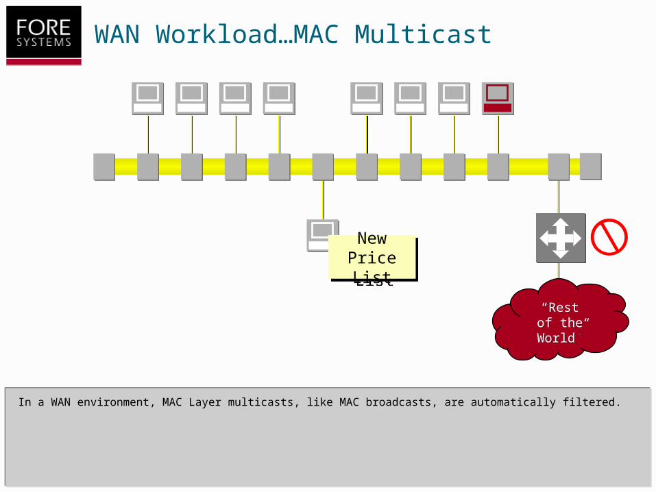
WAN Workload…MAC Multicast
In a WAN environment, MAC Layer multicasts, like MAC broadcasts, are automatically filtered.
“Rest of the
World”
“Rest of the
World”
New Price List
New Price List
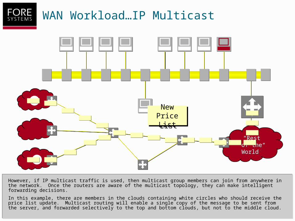
WAN Workload…IP Multicast
However, if IP multicast traffic is used, then multicast group members can join from anywhere in the network. Once the routers are aware of the multicast topology, they can make intelligent forwarding decisions.
In this example, there are members in the clouds containing white circles who should receive the price list update. Multicast routing will enable a single copy of the message to be sent from the server, and forwarded selectively to the top and bottom clouds, but not to the middle cloud.
“Rest of the
World”
“Rest of the
World”
New Price List
New Price List

Summary of Part 1
There are three different address formats used on a conventional, frame-based LAN. Unicasts, in which only one end system in the segment will respond to the address. Broadcasts, in which all end systems on the LAN segment will respond to the address. Multicasts, in which selected groups of end systems will respond to the address.
• There are three different address types on frame-based LANs
– Unicast
– Broadcast
– Multicast
• Each frame type has a specific use
• Each frame type has an impact on performance
– Workstation Performance
– Segment Performance
– Extended Network Performance

Summary of Part 1
Each of the frame types has a specific use in the network. Unicasts are used for private conversations between pairs of end systems.
Broadcasts are generally used for the resolution of name or address information, or for status updates (eg. Routing updates, name table updates, etc.).
Multicasts are a more controlled option for status updates, and also have a specific role in terms of multicast application deployment.
• There are three different address types on frame-based LANs
– Unicast
– Broadcast
– Multicast
• Each frame type has a specific use
• Each frame type has an impact on performance
– Workstation Performance
– Segment Performance
– Extended Network Performance

Summary of Part 1
The use of each frame type has an impact on the overall performance of the system. This impact can be expressed in terms of the effect on the workstation, the effect on the LAN segment and the effect on the extended network.
• There are three different address types on frame-based LANs
– Unicast
– Broadcast
– Multicast
• Each frame type has a specific use
• Each frame type has an impact on performance
– Workstation Performance
– Segment Performance
– Extended Network Performance
The End
This concludes the tutorial.
If you aren’t viewing this tutorial on the FORE Systems’ ATM Academy Site, then you can find additional tutorials at:
http://academy.fore.com/