Embed Size (px)
Citation preview
������������� ��� �������������������������������������������� ����!������������������������
���������
���� ���� ������������������������������ ���� ��!��"������������#��������������!#��� ����������$���
Robert P. CharetteHarold E. Marshall
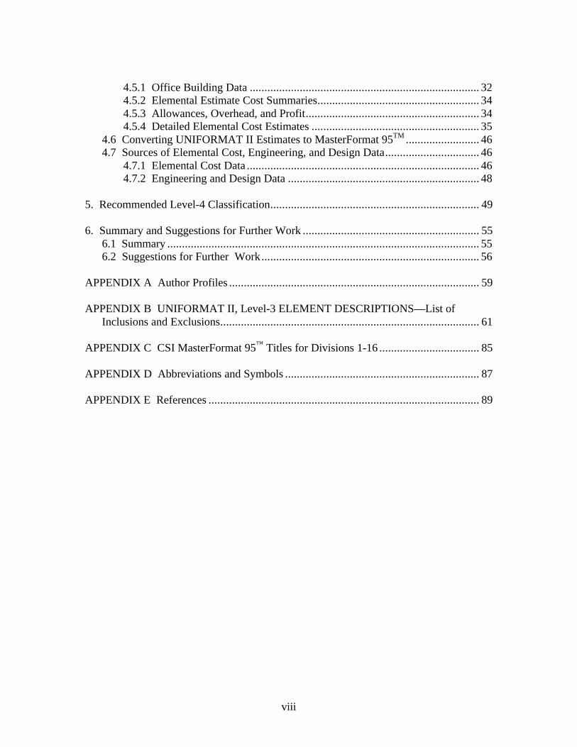
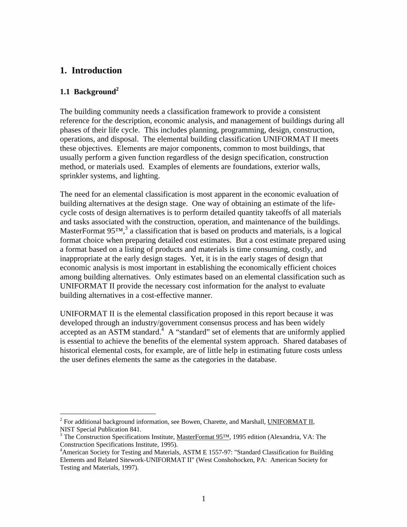
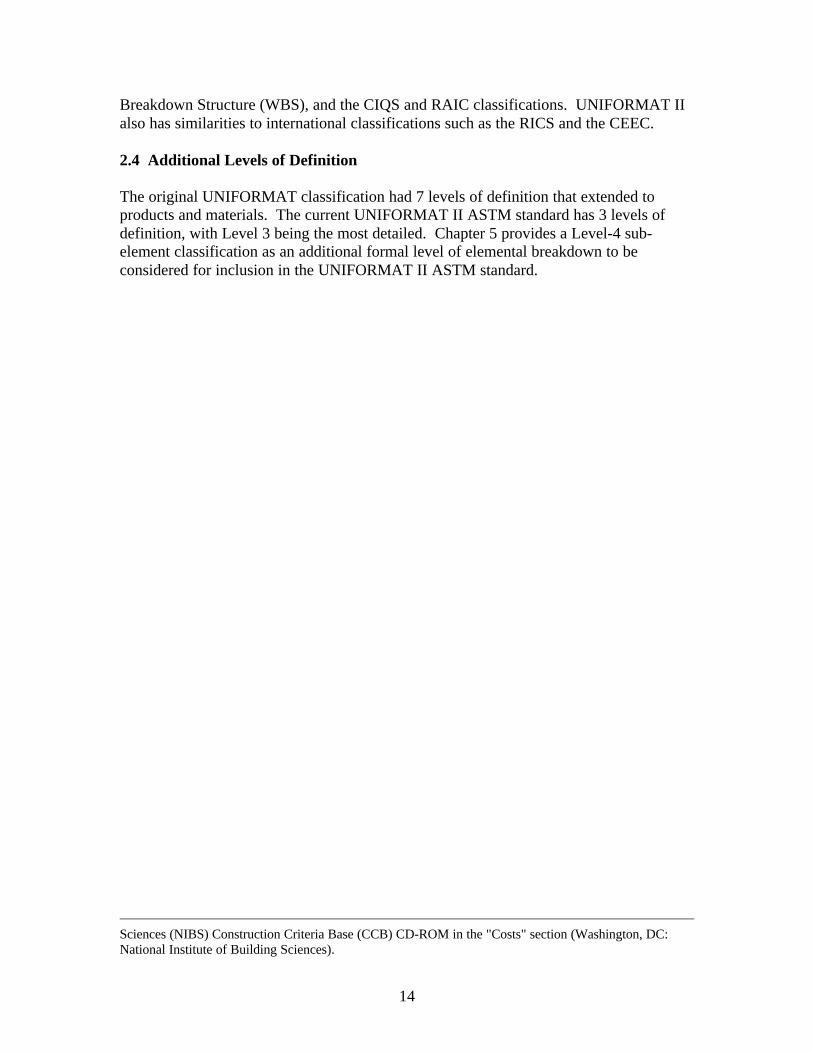
ASTM Uniformat II Classification for Building Elements (E1557-97)Level 1
Major Group ElementsLevel 2
Group ElementsLevel 3
Individual ElementsA10 Foundations A1010 Standard Foundations
A1020 Special FoundationsA1030 Slab on Grade
A SUBSTRUCTURE
A20 Basement Construction A2010 Basement ExcavationA2020 Basement Walls
B10 Superstructure B1010 Floor ConstructionB1020 Roof Construction
B20 Exterior Enclosure B2010 Exterior WallsB2020 Exterior WindowsB2030 Exterior Doors
B SHELL
B30 Roofing B3010 Roof CoveringsB3020 Roof Openings
C10 Interior Construction C1010 PartitionsC1020 Interior DoorsC1030 Fittings
C20 Stairs C2010 Stair ConstructionC2020 Stair Finishes
C INTERIORS
C30 Interior Finishes C3010 Wall FinishesC3020 Floor FinishesC3030 Ceiling Finishes
D10 Conveying D1010 Elevators & LiftsD1020 Escalators & Moving WalksD1090 Other Conveying Systems
D20 Plumbing D2010 Plumbing FixturesD2020 Domestic Water DistributionD2030 Sanitary WasteD2040 Rain Water DrainageD2090 Other Plumbing Systems
D30 HVAC D3010 Energy SupplyD3020 Heat Generating SystemsD3030 Cooling Generating SystemsD3040 Distribution SystemsD3050 Terminal & Package UnitsD3060 Controls & InstrumentationD3070 Systems Testing & BalancingD3090 Other HVAC Systems & Equipment
D40 Fire Protection D4010 SprinklersD4020 StandpipesD4030 Fire Protection SpecialtiesD4090 Other Fire Protection Systems
D SERVICES
D50 Electrical D5010 Electrical Service &Distribution
D5020 Lighting and Branch WiringD5030 Communications & SecurityD5090 Other Electrical Systems
E10 Equipment E1010 Commercial EquipmentE1020 Institutional EquipmentE1030 Vehicular EquipmentE1090 Other Equipment
E EQUIPMENT & FURNISHINGS
E20 Furnishings E2010 Fixed FurnishingsE2020 Movable Furnishings
F10 Special Construction F1010 Special StructuresF1020 Integrated ConstructionF1030 Special Construction SystemsF1040 Special FacilitiesF1050 Special Controls and Instrumentation
F SPECIAL CONSTRUCTION & DEMOLITION
F20 Selective Building Demolition
F2010 Building Elements DemolitionF2020 Hazardous Components Abatement
������������� ��� �������������������������������������������� ����!������������������������
���������
���� ���� �� ��������������������������� ���� ��!��"������������#����������������!#�� ����������$���
Robert P. CharetteConcordia UniversityMontreal, Canada
and
Harold E. MarshallOffice of Applied EconomicsBuilding and Fire Research LaboratoryNational Institute of Standards and Technology
October 1999
U.S. DEPARTMENT OF COMMERCEWilliam M. Daley, Secretary
Technology AdministrationCheryl L. Shavers, Under Secretary for Technology
National Institute of Standards and TechnologyRaymond G. Kammer, Director

i
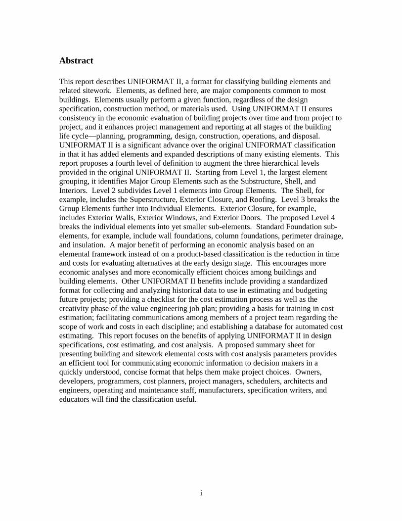
Abstract
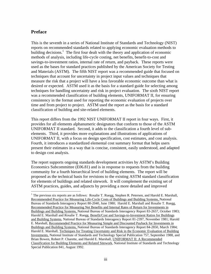
This report describes UNIFORMAT II, a format for classifying building elements andrelated sitework. Elements, as defined here, are major components common to mostbuildings. Elements usually perform a given function, regardless of the designspecification, construction method, or materials used. Using UNIFORMAT II ensuresconsistency in the economic evaluation of building projects over time and from project toproject, and it enhances project management and reporting at all stages of the buildinglife cycle—planning, programming, design, construction, operations, and disposal.UNIFORMAT II is a significant advance over the original UNIFORMAT classificationin that it has added elements and expanded descriptions of many existing elements. Thisreport proposes a fourth level of definition to augment the three hierarchical levelsprovided in the original UNIFORMAT II. Starting from Level 1, the largest elementgrouping, it identifies Major Group Elements such as the Substructure, Shell, andInteriors. Level 2 subdivides Level 1 elements into Group Elements. The Shell, forexample, includes the Superstructure, Exterior Closure, and Roofing. Level 3 breaks theGroup Elements further into Individual Elements. Exterior Closure, for example,includes Exterior Walls, Exterior Windows, and Exterior Doors. The proposed Level 4breaks the individual elements into yet smaller sub-elements. Standard Foundation sub-elements, for example, include wall foundations, column foundations, perimeter drainage,and insulation. A major benefit of performing an economic analysis based on anelemental framework instead of on a product-based classification is the reduction in timeand costs for evaluating alternatives at the early design stage. This encourages moreeconomic analyses and more economically efficient choices among buildings andbuilding elements. Other UNIFORMAT II benefits include providing a standardizedformat for collecting and analyzing historical data to use in estimating and budgetingfuture projects; providing a checklist for the cost estimation process as well as thecreativity phase of the value engineering job plan; providing a basis for training in costestimation; facilitating communications among members of a project team regarding thescope of work and costs in each discipline; and establishing a database for automated costestimating. This report focuses on the benefits of applying UNIFORMAT II in designspecifications, cost estimating, and cost analysis. A proposed summary sheet forpresenting building and sitework elemental costs with cost analysis parameters providesan efficient tool for communicating economic information to decision makers in aquickly understood, concise format that helps them make project choices. Owners,developers, programmers, cost planners, project managers, schedulers, architects andengineers, operating and maintenance staff, manufacturers, specification writers, andeducators will find the classification useful.

ii
iii
Preface
This is the seventh in a series of National Institute of Standards and Technology (NIST)reports on recommended standards related to applying economic evaluation methods tobuilding decisions.1 The first four dealt with the theory and application of economicmethods of analysis, including life-cycle costing, net benefits, benefit-to-cost andsavings-to-investment ratios, internal rate of return, and payback. These reports wereused as the bases for standard practices published by the American Society for Testingand Materials (ASTM). The fifth NIST report was a recommended guide that focused ontechniques that account for uncertainty in project input values and techniques thatmeasure the risk that a project will have a less favorable economic outcome than what isdesired or expected. ASTM used it as the basis for a standard guide for selecting amongtechniques for handling uncertainty and risk in project evaluation. The sixth NIST reportwas a recommended classification of building elements, UNIFORMAT II, for ensuringconsistency in the format used for reporting the economic evaluation of projects overtime and from project to project. ASTM used the report as the basis for a standardclassification of building and site-related elements.
This report differs from the 1992 NIST UNIFORMAT II report in four ways. First, itprovides for all elements alphanumeric designators that conform to those of the ASTMUNIFORMAT II standard. Second, it adds to the classification a fourth level of sub-elements. Third, it provides more explanations and illustrations of applications ofUNIFORMAT II, with a focus on design specification, cost estimates, and cost analysis.Fourth, it introduces a standardized elemental cost summary format that helps userspresent their estimates in a way that is concise, consistent, easily understood, and adaptedto design cost analysis.
The report supports ongoing standards development activities by ASTM’s BuildingEconomics Subcommittee (E06.81) and is in response to requests from the buildingcommunity for a fourth hierarchical level of building elements. The report will beproposed as the technical basis for revisions to the existing ASTM standard classificationfor elements of buildings and related sitework. It will complement the existing set ofASTM practices, guides, and adjuncts by providing a more detailed and improved 1 The previous six reports are as follows: Rosalie T. Ruegg, Stephen R. Petersen, and Harold E. Marshall,Recommended Practice for Measuring Life-Cycle Costs of Buildings and Building Systems, NationalBureau of Standards Interagency Report 80-2040, June 1980; Harold E. Marshall and Rosalie T. Ruegg,Recommended Practice for Measuring Net Benefits and Internal Rates of Return for Investments inBuildings and Building Systems, National Bureau of Standards Interagency Report 83-2657, October 1983;Harold E. Marshall and Rosalie T. Ruegg, Benefit/Cost and Savings-to-Investment Ratios for Buildingsand Building Systems, National Bureau of Standards Interagency Report 81-2397, November 1981; HaroldE. Marshall, Recommended Practice for Measuring Simple and Discounted Payback for Investments inBuildings and Building Systems, National Bureau of Standards Interagency Report 84-2850, March 1984;Harold E. Marshall, Techniques for Treating Uncertainty and Risk in the Economic Evaluation of BuildingInvestments, National Institute of Standards and Technology Special Publication 757, September 1988, andBrian Bowen, Robert P. Charette, and Harold E. Marshall, UNIFORMAT II: A RecommendedClassification for Building Elements and Related Sitework, National Institute of Standards and TechnologySpecial Publication 841, August 1992.
iv
classification for collecting and evaluating costs in the economic evaluation of buildingsand building systems. The report’s format for presenting an elemental cost summary willbe proposed as the basis of a new ASTM standard classification for elemental costsummaries.
Note: The policy of the National Institute of Standards and Technology is to use theInternational System of Units (SI) for all measurements in its publications. However, inthe construction and construction materials industries in North America, certain non-SIunits are so widely used that it is more practical and less confusing to includemeasurement values for customary units only in the document. For example, much of thetabular material in the report comes from cost estimating guides, which use customaryunits. The appendix entitled “Symbols” lists all of the measurement symbols and theirmeanings as used in the report.
Disclaimer: Certain trade names and company products are mentioned in the text oridentified in an illustration in order to adequately specify the experimental procedure andequipment used. In no case does such an identification imply recommendation orendorsement by the National Institute of Standards and Technology, nor does it implythat the products are necessarily the best available for the purpose.
v
Acknowledgments
Thanks are due to the ASTM members and others who participated in the discussions ofan improved UNIFORMAT II for building elements and thereby helped determine theframework of this report. Technical support from professional societies and the publicand private sectors contributed to arriving at a consensus for the new fourth level ofclassification. Special appreciation is extended to Brian Bowen, President of Hanscomb,Inc., for his contribution to the development of the Level 4 UNIFORMAT II; to RobertChapman of NIST for his technical contributions; to Sandra Kelley and Cathy Linthicumfor their typing and preparation of the document for printing; and to Amy Boyles for herassistance in computer formatting of tables. Thanks are also due to John Ferguson, R.S.Means Co., Inc., for his help in identifying appropriate costs for inclusion in the chartsand tables, and to Ayers Saint Gross, Architects and Planners, for the cover artwork ofthe Johns Hopkins University School of Nursing.

vi
vii
Table of Contents
Abstract ........................................................................................................................... i
Preface ........................................................................................................................... iii
Acknowledgments........................................................................................................... v
Table of Contents .......................................................................................................... vii
List of Figures................................................................................................................ ix
List of Tables .................................................................................................................. x
List of Charts ................................................................................................................. xi
1. Introduction................................................................................................................ 11.1 Background ........................................................................................................ 11.2 History................................................................................................................ 21.3 Purpose and Benefits .......................................................................................... 31.4 The Building Life Cycle ..................................................................................... 51.5 Organization ....................................................................................................... 8
2. UNIFORMAT II ...................................................................................................... 112.1 Standard Classification of Elements.................................................................. 112.2 Criteria for Classification.................................................................................. 112.3 The Relationship of UNIFORMAT II to Other Elemental Classifications ......... 132.4 Additional Levels of Definition ........................................................................ 14
3. Applying UNIFORMAT II For Specifications.......................................................... 153.1 Overview.......................................................................................................... 153.2 Performance Specifications............................................................................... 173.3 Technical Requirements.................................................................................... 183.4 Preliminary Project Description (PPD) ............................................................. 18
4. UNIFORMAT II For Elemental Estimates and Design Cost Analysis....................... 234.1 Overview of Design and Construction Cost Estimates....................................... 234.2 Benefits of Elemental Design Estimates............................................................ 254.3 Elemental Costs................................................................................................ 26
4.3.1 Unit Rates and Quantities ....................................................................... 274.3.2 Assembly Costs ...................................................................................... 284.3.3 Component Costs ................................................................................... 294.3.4 Units of Measurement ............................................................................ 29
4.4 Cost Analysis Parameters ................................................................................. 314.5 Elemental Cost Estimate Summary Format and Case Illustration ...................... 31
viii
4.5.1 Office Building Data .............................................................................. 324.5.2 Elemental Estimate Cost Summaries....................................................... 344.5.3 Allowances, Overhead, and Profit........................................................... 344.5.4 Detailed Elemental Cost Estimates ......................................................... 35
4.6 Converting UNIFORMAT II Estimates to MasterFormat 95TM ......................... 464.7 Sources of Elemental Cost, Engineering, and Design Data................................ 46
4.7.1 Elemental Cost Data ............................................................................... 464.7.2 Engineering and Design Data ................................................................. 48
5. Recommended Level-4 Classification....................................................................... 49
6. Summary and Suggestions for Further Work ............................................................ 556.1 Summary .......................................................................................................... 556.2 Suggestions for Further Work.......................................................................... 56
APPENDIX A Author Profiles ..................................................................................... 59
APPENDIX B UNIFORMAT II, Level-3 ELEMENT DESCRIPTIONS—List ofInclusions and Exclusions........................................................................................ 61
APPENDIX C CSI MasterFormat 95™ Titles for Divisions 1-16 .................................. 85
APPENDIX D Abbreviations and Symbols .................................................................. 87
APPENDIX E References ............................................................................................ 89
ix
List of Figures
Figure 1.1 Five Phases of the Building Life Cycle .......................................................... 6
Figure 4.1 Office Building Plans and Elevation ............................................................. 32
Figure 6.1 Framework of the Built Environment ........................................................... 57
x
List of Tables
Table 4.1 B2010 Exterior Walls—Quality Levels and Unit Costs................................. 26
Table 4.2 Assembly Costs for Floor Construction, Element B1010................................ 28
Table 4.3 UNIFORMAT II Building Elemental Cost Summary for Buildings .............. 36
Table 4.4 UNIFORMAT II Elemental Cost Summary for Sitework.............................. 37
Table 4.5 Total Construction Cost Summary (TCC) ..................................................... 37
Table 4.6 Detailed Elemental Cost Estimates for Buildings .......................................... 38
Table 4.7 Detailed Elemental Cost Estimates for Sitework ........................................... 43
Table 4.8 Elemental Cost Calculations for Element A1010, Standard Foundations ................................................................................................. 45
xi
List of Charts
Chart 1.1 Elemental Classifications ................................................................................ 4
Chart 2.1 ASTM UNIFORMAT II Classification for Building Elements (E1557-97) ... 12
Chart 2.2 ASTM UNIFORMAT II Classification for Building-Related Sitework(E1557-97) ................................................................................................. 13
Chart 3.1 Program and Design Specifications............................................................... 16
Chart 3.2 Performance and Descriptive Specifications For Element B3010, RoofCoverings................................................................................................... 17
Chart 3.3 Examples of UNIFORMAT II Used in Presenting Technical ProgramRequirements ............................................................................................. 19
Chart 3.4 Preliminary Project Description (PPD).......................................................... 20
Chart 4.1 UNIFORMAT II Links Elemental Preliminary Project Descriptions andDesign Cost Estimates ................................................................................ 24
Chart 4.2 Unit Rates for Brick Face Composite Wall, Element B2010.......................... 27
Chart 4.3 Component Costs for Element D3020, 100 MBH Heat Generating System ... 30
Chart 4.4 UNIFORMAT II Elemental Project Description (Level 2) — 8 StoreyOffice Building........................................................................................... 33
Chart 4.5 Relationship of UNIFORMAT to MasterFormat™ ....................................... 47
Chart 5.1 Suggested Level 4 for the UNIFORMAT II Classification of BuildingElements .................................................................................................... 50
Chart 5.2 Suggested Level 4 for the UNIFORMAT II Classification of Building-Related Sitework ........................................................................................ 53

xii
1
1. Introduction
1.1 Background2
The building community needs a classification framework to provide a consistentreference for the description, economic analysis, and management of buildings during allphases of their life cycle. This includes planning, programming, design, construction,operations, and disposal. The elemental building classification UNIFORMAT II meetsthese objectives. Elements are major components, common to most buildings, thatusually perform a given function regardless of the design specification, constructionmethod, or materials used. Examples of elements are foundations, exterior walls,sprinkler systems, and lighting.
The need for an elemental classification is most apparent in the economic evaluation ofbuilding alternatives at the design stage. One way of obtaining an estimate of the life-cycle costs of design alternatives is to perform detailed quantity takeoffs of all materialsand tasks associated with the construction, operation, and maintenance of the buildings.MasterFormat 95™,3 a classification that is based on products and materials, is a logicalformat choice when preparing detailed cost estimates. But a cost estimate prepared usinga format based on a listing of products and materials is time consuming, costly, andinappropriate at the early design stages. Yet, it is in the early stages of design thateconomic analysis is most important in establishing the economically efficient choicesamong building alternatives. Only estimates based on an elemental classification such asUNIFORMAT II provide the necessary cost information for the analyst to evaluatebuilding alternatives in a cost-effective manner.
UNIFORMAT II is the elemental classification proposed in this report because it wasdeveloped through an industry/government consensus process and has been widelyaccepted as an ASTM standard.4 A “standard” set of elements that are uniformly appliedis essential to achieve the benefits of the elemental system approach. Shared databases ofhistorical elemental costs, for example, are of little help in estimating future costs unlessthe user defines elements the same as the categories in the database.
2 For additional background information, see Bowen, Charette, and Marshall, UNIFORMAT II,NIST Special Publication 841.3 The Construction Specifications Institute, MasterFormat 95™, 1995 edition (Alexandria, VA: TheConstruction Specifications Institute, 1995).4American Society for Testing and Materials, ASTM E 1557-97: "Standard Classification for BuildingElements and Related Sitework-UNIFORMAT II" (West Conshohocken, PA: American Society forTesting and Materials, 1997).
2
1.2 History
Hanscomb Associates in the United States developed for the American Institute ofArchitects (AIA) in 1973 an elemental format called MASTERCOST.5 The GeneralServices Administration (GSA) was also developing an elemental format, which wascalled UNIFORMAT. AIA and GSA ultimately agreed on a common format whichbecame known officially as UNIFORMAT. It was incorporated into AIA's practice onconstruction cost management 6 and GSA's project estimating requirements.7
UNIFORMAT never gained "standard" status or Federal recognition as an officialelemental classification. Yet, it is the basis of most elemental formats used in the UnitedStates.
In 1989, the E06.81 ASTM Subcommittee on Building Economics, representing a widespectrum of the construction industry, initiated the development of an ASTM StandardClassification for Building Elements based in part on the original UNIFORMAT. Thenew classification was called UNIFORMAT II to emphasize its ties to the originalUNIFORMAT.
In August of 1992, NIST issued Special Publication 841 entitled UNIFORMAT II - ARecommended Classification for Building Elements and Related Sitework.8 The purposeof the publication was to obtain consensus from the design and construction industry inpreparation for writing an ASTM standard on UNIFORMAT II. ASTM Standard E1557,"Standard Classification for Building Elements and Related Sitework-UNIFORMAT II,"approved in 1993, was the result. The standard was revised in 1997 and designated asE1557-97.9
UNIFORMAT II provides significant advances over the original UNIFORMAT producedfor GSA and AIA. UNIFORMAT II takes into consideration a broader range of buildingtypes than those originally considered, and numerous suggestions for improvement madeby practitioners using the original UNIFORMAT were incorporated. These includedsuggestions of the United States defense agencies that were also using variants ofUNIFORMAT.
Elemental formats were developed in other countries prior to UNIFORMAT in a searchfor a better framework to help perform economic analyses of building projects. Britishquantity surveyors first developed an elemental format after World War II while helpingthe Department of Education develop a cost planning and cost control approach in
5 American Institute of Architects, MASTERCOST Instruction Manual (Washington, DC: AmericanInstitute of Architects, 1974).6 American Institute of Architects, "Practice 3.73—Construction Cost Management," The ArchitectsHandbook of Professional Practice—7th Edition (Washington, DC: American Institute of Architects, 1992),pp. 681-702.7 General Services Administration, Handbook PBS P3440.5, Project Estimating Requirements(Washington, DC: General Services Administration, August 24, 1981).8 Bowen, Charette, and Marshall, UNIFORMAT II, NIST Special Publication 841.9 ASTM Standard E 1557-97: "Standard Classification for Building Elements and Related Sitework."
3
rebuilding and expanding the British school system.10 This led to the Royal Institution ofChartered Surveyors (RICS) publishing a standard list of elements11 in 1969 that thebuilding community uses routinely in the United Kingdom. As quantity surveyors whotrained in Britain performed their jobs around the globe, they took the elemental formatwith them. By 1972, the Canadian Institute of Quantity Surveyors promulgated its ownstandard classification of elements for buildings12 which was subsequently adopted by theRoyal Architectural Institute of Canada (RAIC). The United Kingdom, Belgium,Germany, France, Ireland, Switzerland, Denmark, South Africa, Japan, the Netherlands,Hong Kong, and many of the former British colonies now have an elementalclassification system. The need for a universal elemental system has encouraged theInternational Council for Building Research Studies and Documentation (CIB) and theConstruction Economics European Committee (CEEC) to establish an elemental formatto collect costs for international exchange. A major objective of the CEEC format is tomake it compatible with the existing formats of as many European countries as possible.However, the CEEC format has not been widely adopted.
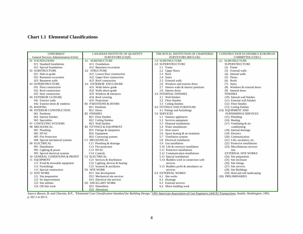
Chart 1.1 summarizes the four elemental classifications referred to earlier —UNIFORMAT, sponsored by GSA and AIA, variants of which are used informally in theUnited States; the Canadian CIQS classification; the United Kingdom RICSclassification, and the European CEEC classification for data exchange.
1.3 Purpose and Benefits
There are three purposes of this report: (1) to expand the classification to a fourth level ofdefinition which would form the basis for revising and expanding the UNIFORMAT IIASTM standard, E1557-97; (2) to describe several applications of the UNIFORMAT IIclassification and the benefits of its use over the phases of a building project's life cycle,with particular emphasis on specifications and estimates during programming and design;and (3) to recommend a standard format for summarizing an elemental cost estimateusing UNIFORMAT II.
The prime benefit of applying UNIFORMAT II as described in this report is to increaseefficiency in carrying out each phase of the building life cycle defined in section 1.4.
10 For a history of the quantity surveying profession in the United Kingdom, see Nisbet, James, Called toAccount—Quantity Surveying 1936-1986 (London, England: Stokes Publications, 1989).11 Royal Institution of Chartered Surveyors (RICS), Standard Form of Cost Analysis (London, England:The Building Cost Information Service, 1969 (reprinted December 1987)).12 Canadian Institute of Quantity Surveyors, Elemental Cost Analysis—Method of Measurement andPricing (Toronto, Ontario, Canada: Canadian Institute of Quantity Surveyors, first issued 1972, revised1990).
4
Chart 1.1 Elemental Classifications
UNIFORMATGeneral Services Administration (GSA)
CANADIAN INSTITUTE OF QUANTITYSURVEYORS (CIQS)
THE ROYAL INSTITUTION OF CHARTEREDSURVEYORS (RICS-UK)
CONSTRUCTION ECONOMICS EUROPEANCOMMITTEE (CEEC)
01 FOUNDATIONS A1 SUBSTRUCTURE 1.0 SUBSTRUCTURE (1) SUBSTRUCTURE 011 Standard foundations A11 Foundations 2.0 SUPERSTRUCTURE SUPERSTRUCTURE 012 Special foundations A12 Basement excavation 2.1 Frame (2) Frame02 SUBSTRUCTURE A2 STRUCTURE 2.2 Upper floors (3) External walls 021 Slab on grade A21 Lowest floor construction 2.3 Roof (4) Internal walls 022 Basement excavation A22 Upper floor construction 2.4 Stairs (5) Floors 023 Basement walls A23 Roof construction 2.5 External walls (6) Roofs03 SUPERSTRUCTURE A3 EXTERIOR ENCLOSURE 2.6 Windows and exterior doors (7) Stairs 031 Floor construction A31 Walls below grade 2.7 Interior walls & interior partitions (8) Windows & external doors 032 Roof construction A32 Walls above grade 2.8 Interior doors (9) Internal doors 033 Stair construction A33 Windows & entrances 3.0 INTERNAL FINISHES FINISHES04 EXTERIOR CLOSURE A34 Roof covering 3.1 Wall finishes (10) Internal wall finishes 041 Exterior walls A35 Projections 3.2 Floor finishes (11) External wall finishes 042 Exterior doors & windows B1 PARTITIONS & DOORS 3.3 Ceiling finishes (12) Floor finishes05 ROOFING B11 Partitions 4.0 FITTINGS AND FURNITURE (13) Ceiling finishes06 INTERIOR CONSTRUCTION B12 Doors 4.1 Fittings and furnishings (14) EQUIPMENT AND 061 Partitions B2 FINISHES 5.0 SERVICES FURNISHINGS SERVICES 062 Interior finishes B21 Floor finishes 5.1 Sanitary appliances (15) Plumbing 063 Specialties B22 Ceiling finishes 5.2 Services equipment (16) Heating07 CONVEYING SYSTEMS B23 Wall finishes 5.3 Disposal installations (17) Ventilating & air-08 MECHANICAL B3 FITTINGS & EQUIPMENT 5.4 Water installations conditioning 081 Plumbing B31 Fittings & equipment 5.5 Heat source (18) Internal drainage 082 HVAC B32 Equipment 5.6 Space heating & air treatment (19) Electrics 083 Fire Protection B33 Conveying systems 5.7 Ventilation systems (20) Communication 084 Special mechanical systems C1 MECHANICAL 5.8 Electrical installation (21) Lifts, escalators, etc.09 ELECTRICAL C11 Plumbing & drainage 5.9 Gas installation (22) Protective installations 091 Distribution C12 Fire protection 5.10 Life & conveyor installation (23) Miscellaneous services 092 Lighting & power C13 HVAC 5.11 Protective installations inst. 093 Special electrical systems C14 Controls 5.12 Communication installations EXTERNAL SITE WORKS10 GENERAL CONDITIONS & PROFIT C2 ELECTRICAL 5.13 Special installations (24) Site preparation11 EQUIPMENT C21 Services & distribution 5.14 Builders work in connection with (25) Site enclosure 111 Fixed & moveable equipment C22 Lighting, devices & heating services (26) Site fittings 112 Furnishings C23 Systems & ancillaries 5.15 Builders profit & attendance on (27) Site services 113 Special construction D1 SITE WORK services (28) Site Buildings12 SITE WORK D11 Site development 6.0 EXTERNAL WORKS (29) Hard and soft landscaping 121 Site preparation D12 Mechanical site services 6.1 Site works (30) PRELIMINARIES 122 Sit improvements D13 Electrical site services 6.2 Drainage 123 Site utilities D2 ANCILLARY WORK 6.3 External services 124 Off-Site work D21 Demolition
D22 Alterations 6.4 Minor building work
Source:Bowen, B. and Charette, R.P., "Elemental Cost Classification Standard for Building Design,"1991 American Association of Cost Engineers (AACE) Transactions, Seattle, Washington, 1991,p. H2-1 to H2-5.
5
Applying UNIFORMAT II at each step of the building process provides significantsavings to industry. Data entered in a consistent format will not have to be reentered atsubsequent phases of the building life cycle. Users will understand and be able tocompare information at every phase because it is linked to a common, uniform,standardized, elemental classification structure. Better information, generated at lesscost, will help owners, project managers, designers, builders, facility managers, and usersbuild and manage their buildings for lower life-cycle costs.
1.4 The Building Life Cycle
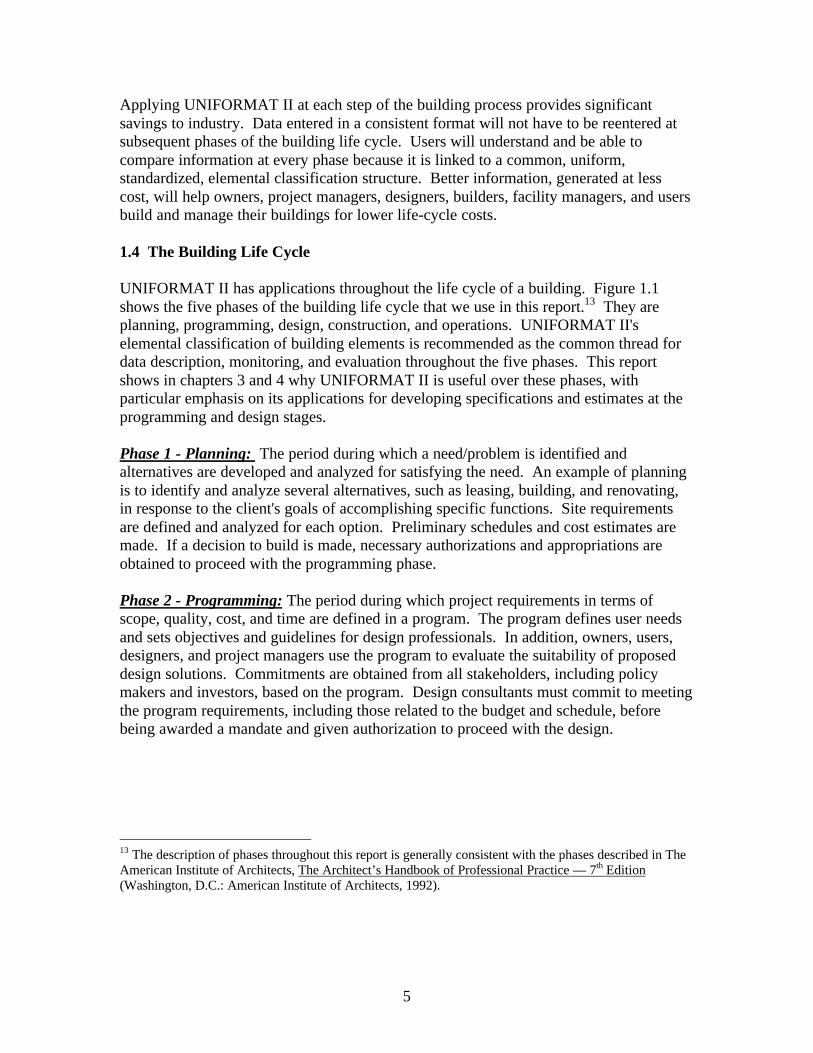
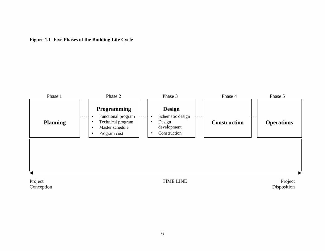
UNIFORMAT II has applications throughout the life cycle of a building. Figure 1.1shows the five phases of the building life cycle that we use in this report.13 They areplanning, programming, design, construction, and operations. UNIFORMAT II'selemental classification of building elements is recommended as the common thread fordata description, monitoring, and evaluation throughout the five phases. This reportshows in chapters 3 and 4 why UNIFORMAT II is useful over these phases, withparticular emphasis on its applications for developing specifications and estimates at theprogramming and design stages.
Phase 1 - Planning: The period during which a need/problem is identified andalternatives are developed and analyzed for satisfying the need. An example of planningis to identify and analyze several alternatives, such as leasing, building, and renovating,in response to the client's goals of accomplishing specific functions. Site requirementsare defined and analyzed for each option. Preliminary schedules and cost estimates aremade. If a decision to build is made, necessary authorizations and appropriations areobtained to proceed with the programming phase.
Phase 2 - Programming: The period during which project requirements in terms ofscope, quality, cost, and time are defined in a program. The program defines user needsand sets objectives and guidelines for design professionals. In addition, owners, users,designers, and project managers use the program to evaluate the suitability of proposeddesign solutions. Commitments are obtained from all stakeholders, including policymakers and investors, based on the program. Design consultants must commit to meetingthe program requirements, including those related to the budget and schedule, beforebeing awarded a mandate and given authorization to proceed with the design.
13 The description of phases throughout this report is generally consistent with the phases described in TheAmerican Institute of Architects, The Architect’s Handbook of Professional Practice — 7th Edition(Washington, D.C.: American Institute of Architects, 1992).
6
Figure 1.1 Five Phases of the Building Life Cycle
Phase 1 Phase 2 Phase 3 Phase 4 Phase 5
Project TIME LINE ProjectConception Disposition
Planning
Programming• Functional program• Technical program• Master schedule• Program cost
Design• Schematic design• Design
development• Construction
documents
Construction Operations
7
We consider the program as having four principal sections:14 (1) a functional program;(2) a technical program; (3) a master schedule; and (4) a program cost estimate. Thefunctional program documents and analyzes spatial relations; the number of occupantsand their functional responsibility; space requirements expressed in both net and grossareas; and constraints. Site functional requirements are also documented and analyzed.
The technical program provides designers the performance specifications and technicalrequirements for the building elements and individual spaces. Performance specificationsdescribe requirements in a manner that (1) indicates required results and (2) provides thecriteria for verifying compliance with the specifications without stating how to achievethe results. Technical requirements are specific client directives and other technicalinformation given to designers with respect to building systems, products, materials,design criteria, standards, practices, codes, and constraints. Organizations that constructfacilities on a continuing basis, such as government agencies, the military, universities,large corporations, restaurant franchises, and chain stores generally incorporate technicalrequirements in their "Design Standards" documentation.
The master schedule for design and construction presents a plan of the major projecttasks/milestones and completion dates. Project delivery options are analyzed in preparingthe program schedule to determine the most cost-effective alternatives that meet theclient's objectives.
The program cost estimate is based on the functional and technical programrequirements. It provides a distribution of costs by building elements within the allocatedbudget. These costs reflect the performance and quality levels (See Table 4.1)anticipated by the client. This estimate is also a cost plan for comparing subsequentestimates and for monitoring and controlling costs as design progresses.
Phase 3 - Design: The period during which stated needs in the program are translated toplans and specifications. Detailed solutions to program requirements, updated costestimates, and revised schedules are submitted for client approval as design progresses.Funds are appropriated, bids requested, and contracts awarded.The facilities design is typically prepared in a series of three, sequential, design sub-phases (Phase 3 block in figure 1.1). In each, the architect brings the design to an interimlevel of development, updates estimates, has the owner review and approve the work, andmoves the project forward to the next level. The three sub-phases are schematic design,design development, and construction documents.
Schematic design establishes the general scope, conceptual design, and the scalerelationships among the parts of the project. The primary goal is to clearly define afeasible concept within the allocated budget in a form that clients understand and approvebefore proceeding to design development.
14 The composition of Phases 2 and 3 is shown in figure 1.1. We treat the programming phase and thefollowing design phase in greater detail than the other phases because the focus of our UNIFORMAT IIapplications in chapters 3 and 4 is on these two phases.
8
In design development, all aspects of the design for each discipline are developed andcoordinated. Drawings and specifications include floor plans, sections, exteriorelevations, and for some parts of the building, interior elevations, reflected ceiling plans,wall sections, and key details. Basic mechanical, electrical, plumbing, and fire protectionsystems are also defined. Design development ends with approval by the owner of theplans, projected cost, and schedule.
In the construction documents sub-phase, the design team works on the final material andsystem selections, details, and dimensions. Final plans and construction specificationsare provided to bidders, and contracts are awarded.
Phase 4 - Construction: The period during which plans and specifications areimplemented into a finished structure which conforms to the specification requirements,construction schedule, and budget. Following commissioning, the building is ready foroccupancy by the user.
Phase 5 - Operations: The longest phase of a building's life cycle, during which it isoperated to fulfill the owner's objectives. It is initiated at the date of beneficialoccupancy. During this phase, a building may be retrofitted or recycled for a newfunction any number if times. Its life is terminated when the building is decommissionedand removed from the site.
1.5 Organization
Chapter 2 introduces the ASTM E1557-97 UNIFORMAT II classification that comprisesthree hierarchical levels for both building elements and related sitework elements. Thechapter also presents the criteria used to determine which categories of elements wereincluded and in what part of the hierarchy to include them. This classification differsfrom the 1992 version of UNIFORMAT II in NIST SP 841 in two respects: it has (1) analphanumeric organizational system for all elements in the hierarchy and (2) revisionsbrought about by five years of the ASTM consensus process.
Chapter 3 describes how to apply UNIFORMAT II in writing performance specifications,technical requirements, and preliminary project descriptions. The chapter also lists andexplains many of the benefits from using UNIFORMAT II in these applications.
Chapter 4 distinguishes elemental estimating from product-based estimating and explainsthe advantages of using elemental estimates in the design of buildings. Examples showthe three ways to calculate element costs--using element unit rates and quantities,assembly costs and quantities, or component costs and quantities. Cost analysisparameters are defined and benefits from applying them are described. The chapterpresents a two-page summary of an elemental estimate for an eight-story office buildingand explains how such a summary format aids communication among projectstakeholders. A list of sources of elemental cost, engineering, and design data completesthe chapter.
9
Chapter 5 presents a proposed list of Level-4 sub-elements for UNIFORMAT II. Theadvantages of having Level-4 sub-elements are described in detail.
Chapter 6 concludes the report with a summary and suggestions for further work.
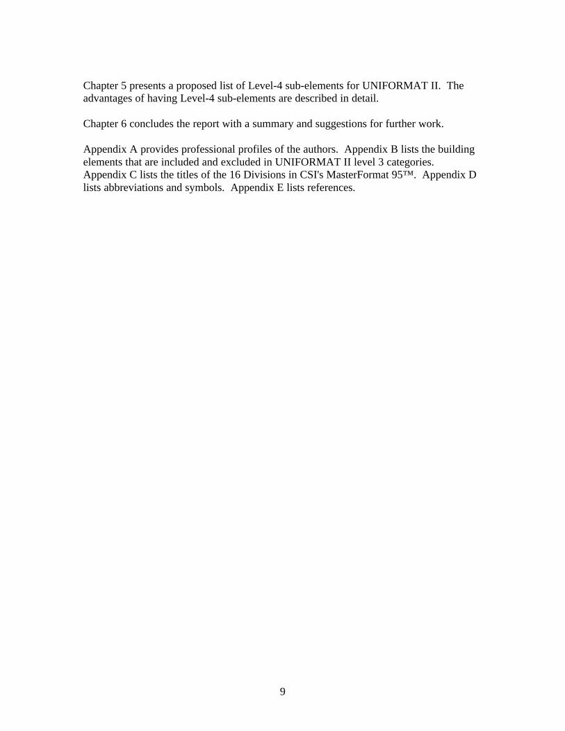
Appendix A provides professional profiles of the authors. Appendix B lists the buildingelements that are included and excluded in UNIFORMAT II level 3 categories.Appendix C lists the titles of the 16 Divisions in CSI's MasterFormat 95™. Appendix Dlists abbreviations and symbols. Appendix E lists references.

10
11
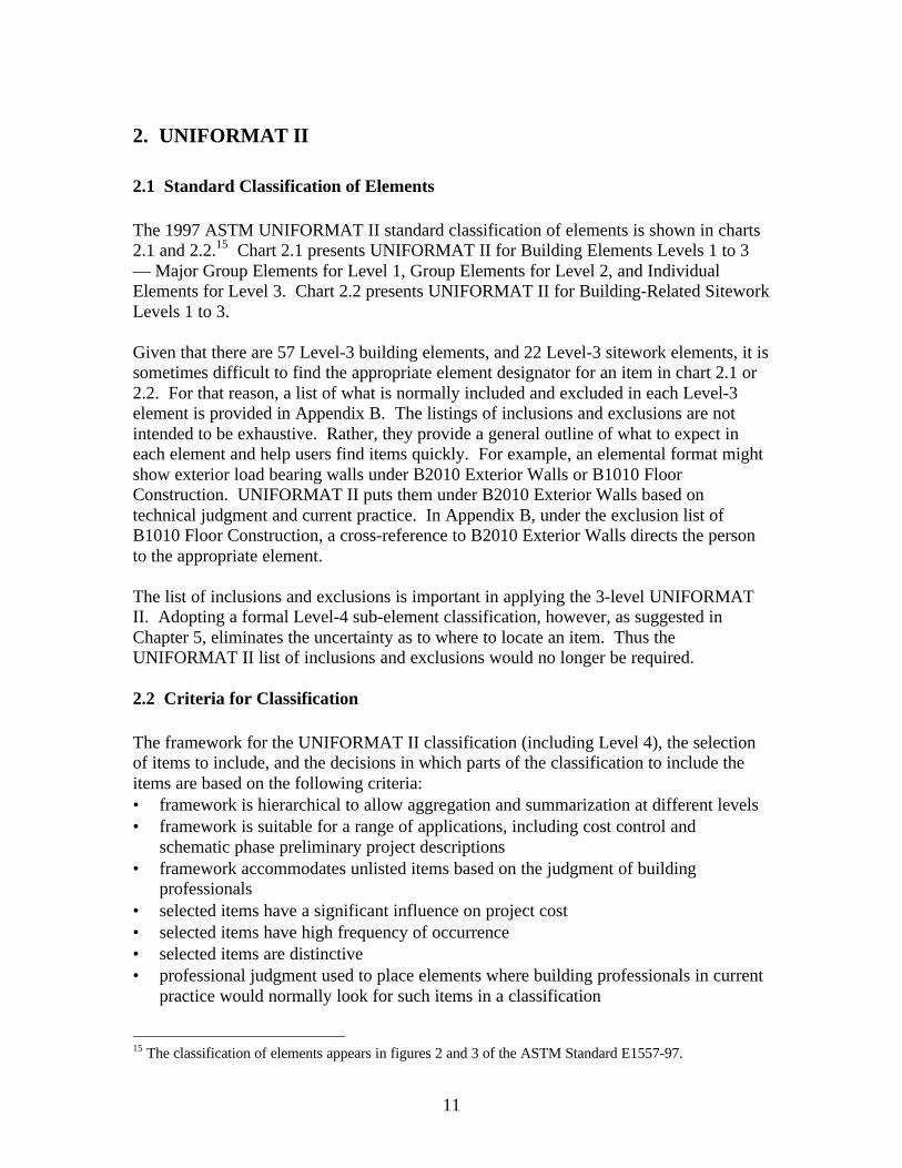
2. UNIFORMAT II
2.1 Standard Classification of Elements
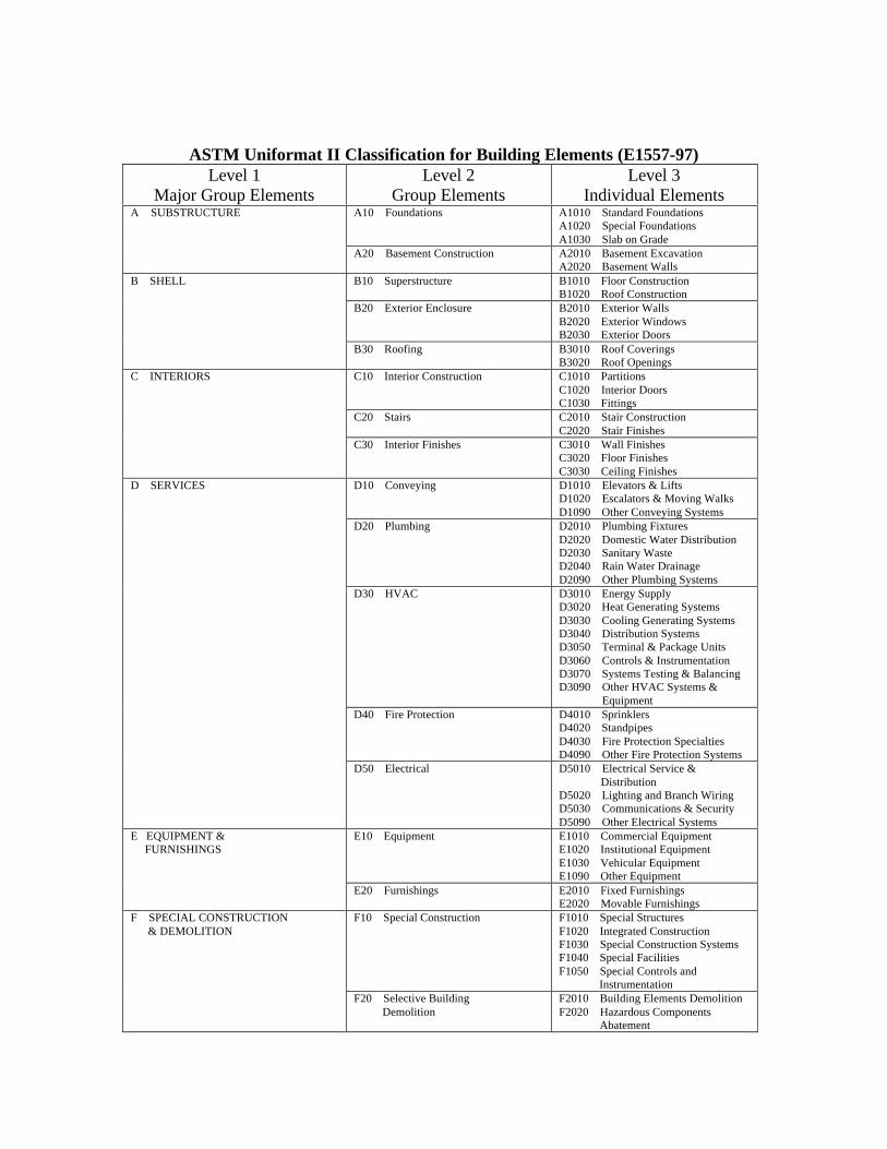
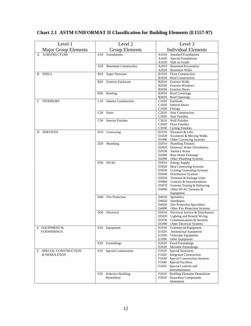
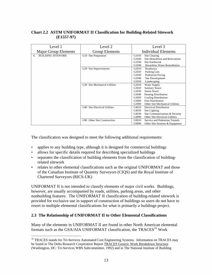
The 1997 ASTM UNIFORMAT II standard classification of elements is shown in charts2.1 and 2.2.15 Chart 2.1 presents UNIFORMAT II for Building Elements Levels 1 to 3— Major Group Elements for Level 1, Group Elements for Level 2, and IndividualElements for Level 3. Chart 2.2 presents UNIFORMAT II for Building-Related SiteworkLevels 1 to 3.
Given that there are 57 Level-3 building elements, and 22 Level-3 sitework elements, it issometimes difficult to find the appropriate element designator for an item in chart 2.1 or2.2. For that reason, a list of what is normally included and excluded in each Level-3element is provided in Appendix B. The listings of inclusions and exclusions are notintended to be exhaustive. Rather, they provide a general outline of what to expect ineach element and help users find items quickly. For example, an elemental format mightshow exterior load bearing walls under B2010 Exterior Walls or B1010 FloorConstruction. UNIFORMAT II puts them under B2010 Exterior Walls based ontechnical judgment and current practice. In Appendix B, under the exclusion list ofB1010 Floor Construction, a cross-reference to B2010 Exterior Walls directs the personto the appropriate element.
The list of inclusions and exclusions is important in applying the 3-level UNIFORMATII. Adopting a formal Level-4 sub-element classification, however, as suggested inChapter 5, eliminates the uncertainty as to where to locate an item. Thus theUNIFORMAT II list of inclusions and exclusions would no longer be required.
2.2 Criteria for Classification
The framework for the UNIFORMAT II classification (including Level 4), the selectionof items to include, and the decisions in which parts of the classification to include theitems are based on the following criteria:• framework is hierarchical to allow aggregation and summarization at different levels• framework is suitable for a range of applications, including cost control and
schematic phase preliminary project descriptions• framework accommodates unlisted items based on the judgment of building
professionals• selected items have a significant influence on project cost• selected items have high frequency of occurrence• selected items are distinctive• professional judgment used to place elements where building professionals in current
practice would normally look for such items in a classification
15 The classification of elements appears in figures 2 and 3 of the ASTM Standard E1557-97.
12
Chart 2.1 ASTM UNIFORMAT II Classification for Building Elements (E1557-97)
Level 1Major Group Elements
Level 2Group Elements
Level 3Individual Elements
A10 Foundations A1010 Standard FoundationsA1020 Special FoundationsA1030 Slab on Grade
A SUBSTRUCTURE
A20 Basement Construction A2010 Basement ExcavationA2020 Basement Walls
B10 Super Structure B1010 Floor ConstructionB1020 Roof Construction
B20 Exterior Enclosure B2010 Exterior WallsB2020 Exterior WindowsB2030 Exterior Doors
B SHELL
B30 Roofing B3010 Roof CoveringsB3020 Roof Openings
C10 Interior Construction C1010 PartitionsC1020 Interior DoorsC1030 Fittings
C20 Stairs C2010 Stair ConstructionC2020 Stair Finishes
C INTERIORS
C30 Interior Finishes C3010 Wall FinishesC3020 Floor FinishesC3030 Ceiling Finishes
D10 Conveying D1010 Elevators & LiftsD1020 Escalators & Moving WalksD1090 Other Conveying Systems
D20 Plumbing D2010 Plumbing FixturesD2020 Domestic Water DistributionD2030 Sanitary WasteD2040 Rain Water DrainageD2090 Other Plumbing Systems
D30 HVAC D3010 Energy SupplyD3020 Heat Generating SystemsD3030 Cooling Generating SystemsD3040 Distribution SystemsD3050 Terminal & Package UnitsD3060 Controls & InstrumentationD3070 Systems Testing & BalancingD3090 Other HVAC Systems & Equipment
D40 Fire Protection D4010 SprinklersD4020 StandpipesD4030 Fire Protection SpecialtiesD4090 Other Fire Protection Systems
D SERVICES
D50 Electrical D5010 Electrical Service & DistributionD5020 Lighting and Branch WiringD5030 Communications & SecurityD5090 Other Electrical Systems
E10 Equipment E1010 Commercial EquipmentE1020 Institutional EquipmentE1030 Vehicular EquipmentE1090 Other Equipment
E EQUIPMENT & FURNISHINGS
E20 Furnishings E2010 Fixed FurnishingsE2020 Movable Furnishings
F10 Special Construction F1010 Special StructuresF1020 Integrated ConstructionF1030 Special Construction SystemsF1040 Special FacilitiesF1050 Special Controls and Instrumentation
F SPECIAL CONSTRUCTION & DEMOLITION
F20 Selective Building Demolition
F2010 Building Elements DemolitionF2020 Hazardous Components Abatement
13
Chart 2.2 ASTM UNIFORMAT II Classification for Building-Related Sitework(E1557-97)
Level 1Major Group Elements
Level 2Group Elements
Level 3Individual Elements
G10 Site Preparation G1010 Site ClearingG1020 Site Demolition and RelocationsG1030 Site EarthworkG1040 Hazardous Waste Remediation
G20 Site Improvements G2010 RoadwaysG2020 Parking LotsG2030 Pedestrian PavingG2040 Site DevelopmentG2050 Landscaping
G30 Site Mechanical Utilities G3010 Water SupplyG3020 Sanitary SewerG3030 Storm SewerG3040 Heating DistributionG3050 Cooling DistributionG3060 Fuel DistributionG3090 Other Site Mechanical Utilities
G40 Site Electrical Utilities G4010 Electrical DistributionG4020 Site LightingG4030 Site Communications & SecurityG4090 Other Site Electrical Utilities
G BUILDING SITEWORK
G90 Other Site Construction G9010 Service and Pedestrian TunnelsG9090 Other Site Systems & Equipment
The classification was designed to meet the following additional requirements:
• applies to any building type, although it is designed for commercial buildings• allows for specific details required for describing specialized buildings• separates the classification of building elements from the classification of building-
related sitework• relates to other elemental classifications such as the original UNIFORMAT and those
of the Canadian Institute of Quantity Surveyors (CIQS) and the Royal Institute ofChartered Surveyors (RICS-UK)
UNIFORMAT II is not intended to classify elements of major civil works. Buildings,however, are usually accompanied by roads, utilities, parking areas, and othernonbuilding features. The UNIFORMAT II classification of building-related sitework isprovided for exclusive use in support of construction of buildings so users do not have toresort to multiple elemental classifications for what is primarily a buildings project.
2.3 The Relationship of UNIFORMAT II to Other Elemental Classifications
Many of the elements in UNIFORMAT II are found in other North American elementalformats such as the GSA/AIA UNIFORMAT classification, the TRACES16 Work
16 TRACES stands for Tri-Services Automated Cost Engineering Systems. Information on TRACES maybe found in The Delta Research Corporation Report TRACES Generic Work Breakdown Structure(Washington, DC: Tri-Services WBS Subcommittee, 1992) and in The National Institute of Building
14
Breakdown Structure (WBS), and the CIQS and RAIC classifications. UNIFORMAT IIalso has similarities to international classifications such as the RICS and the CEEC.
2.4 Additional Levels of Definition
The original UNIFORMAT classification had 7 levels of definition that extended toproducts and materials. The current UNIFORMAT II ASTM standard has 3 levels ofdefinition, with Level 3 being the most detailed. Chapter 5 provides a Level-4 sub-element classification as an additional formal level of elemental breakdown to beconsidered for inclusion in the UNIFORMAT II ASTM standard.
Sciences (NIBS) Construction Criteria Base (CCB) CD-ROM in the "Costs" section (Washington, DC:National Institute of Building Sciences).
15
3. Applying UNIFORMAT II For Specifications
3.1 Overview
While the original UNIFORMAT classification was developed specifically for designphase estimates, UNIFORMAT II is applicable in all phases of a building’s life cycle.The classification is currently applied for:
• Planning Estimates• Program Performance Specifications• Program Technical Requirements• Program Estimates• Preliminary Project Descriptions• Preliminary Construction Schedules and Cash Flow Projections17
• Design Phase Estimates• CAD Layering• Cost Risk Analysis18
• Life-Cycle Cost Analysis Reporting• Function-Cost Models and Brainstorming Checklists in Value Engineering19
• Checklists for Technical Design Reviews• Design-Build Facilities Procurement• Construction Progress Reporting for Interim Payments• Construction Claims Analysis• Building Condition Evaluation• Scope of Work Definition for Building Renovations and Retrofits• Long-Term Capital Replacement Budgeting• Classifying and Filing Product Literature• Organizing Design, Engineering, and Cost Information for Manuals and Databases• Organizing Maintenance and Life-Cycle Cost Data
In this Chapter and Chapter 4, we focus on selected applications of UNIFORMAT II inthe programming and design phases of the building life cycle. Chapter 3 treatsspecifications, and Chapter 4 treats estimates. We select these applications forillustration for two reasons: each building construction project requires specifications andestimates, and significant benefits are expected from the use of UNIFORMAT II.
17 Ahuja, N. Hira, and Campbell, Walter J., Estimating from Concept to Completion (Englewood Cliffs, NJ:Prentice-Hall, Inc., 1988), and The Royal Architectural Institute of Canada, "Cost Planning and CostControl Techniques," Volume 3, Canadian Handbook of Practice for Architects, 1st Edition (Ottawa,Ontario, Canada: The Royal Architectural Institute of Canada, 1978), pp. 43-49.18 American Society for Testing and Materials, ASTM E1496: "Standard Practice for Measuring Cost Riskof Buildings and Building Systems" (West Conshohocken, PA: American Society for Testing andMaterials, 1998).19 Dell'Isola, Michael, "Value Engineering Applications Using UNIFORMAT II," Proceedings of theSociety of American Value Engineers (SAVE) (Atlanta, GA: 1998), pp.72-82.
16
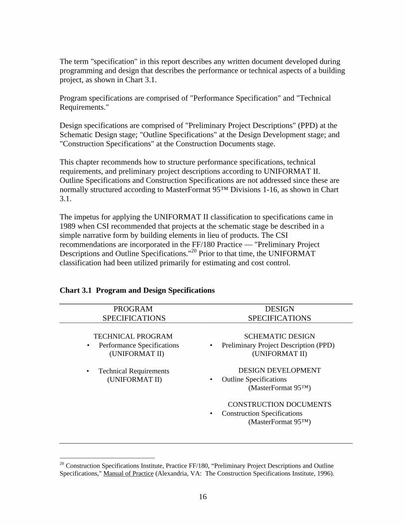
The term "specification" in this report describes any written document developed duringprogramming and design that describes the performance or technical aspects of a buildingproject, as shown in Chart 3.1.
Program specifications are comprised of "Performance Specification" and "TechnicalRequirements."
Design specifications are comprised of "Preliminary Project Descriptions" (PPD) at theSchematic Design stage; "Outline Specifications" at the Design Development stage; and"Construction Specifications" at the Construction Documents stage.
This chapter recommends how to structure performance specifications, technicalrequirements, and preliminary project descriptions according to UNIFORMAT II.Outline Specifications and Construction Specifications are not addressed since these arenormally structured according to MasterFormat 95™ Divisions 1-16, as shown in Chart3.1.
The impetus for applying the UNIFORMAT II classification to specifications came in1989 when CSI recommended that projects at the schematic stage be described in asimple narrative form by building elements in lieu of products. The CSIrecommendations are incorporated in the FF/180 Practice — "Preliminary ProjectDescriptions and Outline Specifications."20 Prior to that time, the UNIFORMATclassification had been utilized primarily for estimating and cost control.
Chart 3.1 Program and Design Specifications
PROGRAM SPECIFICATIONS
DESIGNSPECIFICATIONS
TECHNICAL PROGRAM SCHEMATIC DESIGN• Performance Specifications
(UNIFORMAT II)
• Technical Requirements (UNIFORMAT II)
• Preliminary Project Description (PPD)(UNIFORMAT II)
DESIGN DEVELOPMENT• Outline Specifications
(MasterFormat 95™)
CONSTRUCTION DOCUMENTS• Construction Specifications
(MasterFormat 95™)
20 Construction Specifications Institute, Practice FF/180, “Preliminary Project Descriptions and OutlineSpecifications," Manual of Practice (Alexandria, VA: The Construction Specifications Institute, 1996).
17
3.2 Performance Specifications
Performance specifications set forth results to be achieved but not the means forachieving them. Performance specifications thus differ from prescriptive or descriptivespecifications that describe specific products or systems. With performancespecifications there is more freedom of choice for the materials, fabrication technique,and method of installation. Performance specifications encourage the use of creativityand innovation in fulfilling requirements in a manner that is most economical to theowner. By using UNIFORMAT II to structure the performance specification, an objectreference base is created for evaluating and monitoring the performance of buildingelements throughout the project's life cycle.
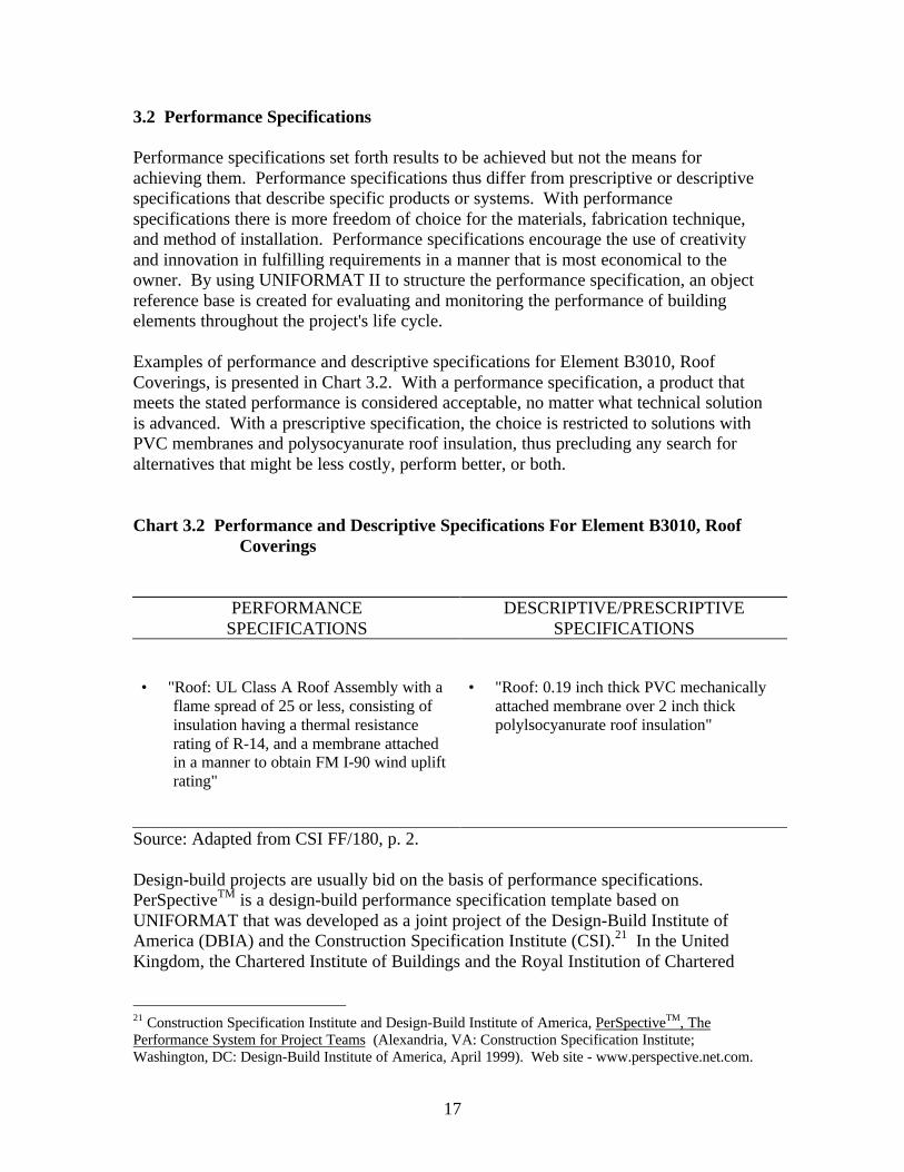
Examples of performance and descriptive specifications for Element B3010, RoofCoverings, is presented in Chart 3.2. With a performance specification, a product thatmeets the stated performance is considered acceptable, no matter what technical solutionis advanced. With a prescriptive specification, the choice is restricted to solutions withPVC membranes and polysocyanurate roof insulation, thus precluding any search foralternatives that might be less costly, perform better, or both.
Chart 3.2 Performance and Descriptive Specifications For Element B3010, RoofCoverings
PERFORMANCESPECIFICATIONS
DESCRIPTIVE/PRESCRIPTIVESPECIFICATIONS
• "Roof: UL Class A Roof Assembly with aflame spread of 25 or less, consisting ofinsulation having a thermal resistancerating of R-14, and a membrane attachedin a manner to obtain FM I-90 wind upliftrating"
• "Roof: 0.19 inch thick PVC mechanicallyattached membrane over 2 inch thickpolylsocyanurate roof insulation"
Source: Adapted from CSI FF/180, p. 2.
Design-build projects are usually bid on the basis of performance specifications.PerSpectiveTM is a design-build performance specification template based onUNIFORMAT that was developed as a joint project of the Design-Build Institute ofAmerica (DBIA) and the Construction Specification Institute (CSI).21 In the UnitedKingdom, the Chartered Institute of Buildings and the Royal Institution of Chartered
21 Construction Specification Institute and Design-Build Institute of America, PerSpectiveTM, ThePerformance System for Project Teams (Alexandria, VA: Construction Specification Institute;Washington, DC: Design-Build Institute of America, April 1999). Web site - www.perspective.net.com.
18
Surveyors also recommend elemental performance specifications for design-buildprojects.22
3.3 Technical Requirements
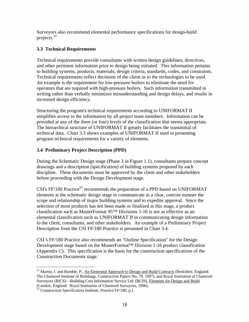
Technical requirements provide consultants with written design guidelines, directives,and other pertinent information prior to design being initiated. This information pertainsto building systems, products, materials, design criteria, standards, codes, and constraints.Technical requirements reflect decisions of the client as to the technologies to be used.An example is the requirement for low-pressure boilers to eliminate the need foroperators that are required with high-pressure boilers. Such information transmitted inwriting rather than verbally minimizes misunderstanding and design delays, and results inincreased design efficiency.
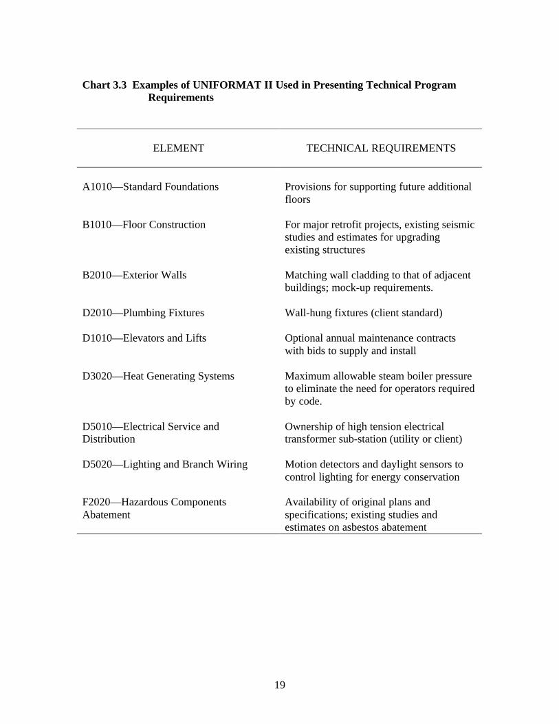
Structuring the program's technical requirements according to UNIFORMAT IIsimplifies access to the information by all project team members. Information can beprovided at any of the three (or four) levels of the classification that seems appropriate.The hierarchical structure of UNIFORMAT II greatly facilitates the transmittal oftechnical data. Chart 3.3 shows examples of UNIFORMAT II used in presentingprogram technical requirements for a variety of elements.
3.4 Preliminary Project Description (PPD)
During the Schematic Design stage (Phase 3 in Figure 1.1), consultants prepare conceptdrawings and a description (specification) of building systems proposed by eachdiscipline. These documents must be approved by the client and other stakeholdersbefore proceeding with the Design Development stage.
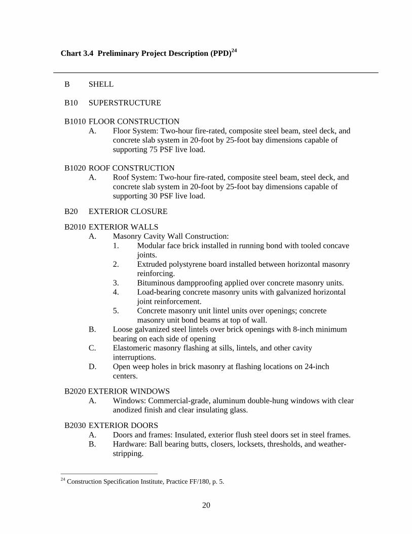
CSI's FF/180 Practice23 recommends the preparation of a PPD based on UNIFORMATelements at the schematic design stage to communicate in a clear, concise manner thescope and relationship of major building systems and to expedite approval. Since theselection of most products has not been made or finalized at this stage, a productclassification such as MasterFormat 95™ Divisions 1-16 is not as effective as anelemental classification such as UNIFORMAT II in communicating design informationto the client, consultants, and other stakeholders. An example of a Preliminary ProjectDescription from the CSI FF/180 Practice is presented in Chart 3.4.
CSI’s FF/180 Practice also recommends an "Outline Specification" for the DesignDevelopment stage based on the MasterFormat™ Division 1-16 product classification(Appendix C). This specification is the basis for the construction specifications of theConstruction Documents stage.
22 Martin, J. and Rumble, P., An Elemental Approach to Design and Build Contracts (Berkshire, England:The Chartered Institute of Buildings, Construction Papers No. 79, 1997), and Royal Institution of CharteredSurveyors (RICS)—Building Cost Information Service Ltd. (BCIS), Elements for Design and Build(London, England: Royal Institution of Chartered Surveyors, 1996).23 Construction Specification Institute, Practice FF/180, p.1.
19
Chart 3.3 Examples of UNIFORMAT II Used in Presenting Technical ProgramRequirements
ELEMENT TECHNICAL REQUIREMENTS
A1010—Standard Foundations Provisions for supporting future additionalfloors
B1010—Floor Construction For major retrofit projects, existing seismicstudies and estimates for upgradingexisting structures
B2010—Exterior Walls Matching wall cladding to that of adjacentbuildings; mock-up requirements.
D2010—Plumbing Fixtures Wall-hung fixtures (client standard)
D1010—Elevators and Lifts Optional annual maintenance contractswith bids to supply and install
D3020—Heat Generating Systems Maximum allowable steam boiler pressureto eliminate the need for operators requiredby code.
D5010—Electrical Service andDistribution
Ownership of high tension electricaltransformer sub-station (utility or client)
D5020—Lighting and Branch Wiring Motion detectors and daylight sensors tocontrol lighting for energy conservation
F2020—Hazardous ComponentsAbatement
Availability of original plans andspecifications; existing studies andestimates on asbestos abatement
20
Chart 3.4 Preliminary Project Description (PPD)24
B SHELL
B10 SUPERSTRUCTURE
B1010 FLOOR CONSTRUCTIONA. Floor System: Two-hour fire-rated, composite steel beam, steel deck, and
concrete slab system in 20-foot by 25-foot bay dimensions capable ofsupporting 75 PSF live load.
B1020 ROOF CONSTRUCTIONA. Roof System: Two-hour fire-rated, composite steel beam, steel deck, and
concrete slab system in 20-foot by 25-foot bay dimensions capable ofsupporting 30 PSF live load.
B20 EXTERIOR CLOSURE
B2010 EXTERIOR WALLSA. Masonry Cavity Wall Construction:
1. Modular face brick installed in running bond with tooled concavejoints.
2. Extruded polystyrene board installed between horizontal masonryreinforcing.
3. Bituminous dampproofing applied over concrete masonry units.4. Load-bearing concrete masonry units with galvanized horizontal
joint reinforcement.5. Concrete masonry unit lintel units over openings; concrete
masonry unit bond beams at top of wall.B. Loose galvanized steel lintels over brick openings with 8-inch minimum
bearing on each side of openingC. Elastomeric masonry flashing at sills, lintels, and other cavity
interruptions.D. Open weep holes in brick masonry at flashing locations on 24-inch
centers.
B2020 EXTERIOR WINDOWSA. Windows: Commercial-grade, aluminum double-hung windows with clear
anodized finish and clear insulating glass.
B2030 EXTERIOR DOORSA. Doors and frames: Insulated, exterior flush steel doors set in steel frames.B. Hardware: Ball bearing butts, closers, locksets, thresholds, and weather-
stripping.
24 Construction Specification Institute, Practice FF/180, p. 5.
21
Some of the benefits from using UNIFORMAT II to structure PPDs at the SchematicDesign stage are the following.
Requiring all disciplines to think the project through at the Schematic Design stage ratherthan at the later Design Development stage reduces cycle time and design costs. TheUNIFORMAT II structure on which the PPD narrative is based makes the project moreunderstandable to all disciplines and stakeholders—the client, project manager, designers,facility managers, and end users. The PPD organized according to the UNIFORMAT IIframework encourages comments more quickly than usual, thereby facilitating andencouraging design changes early in the design process when they are least costly.
Using Levels 3 and 4 of UNIFORMAT II as checklists for all disciplines when definingthe project reduces the probability of omissions in the PPD.
Defining baseline systems in the PPD facilitates preparing elemental cost estimates andallows the analyst to compare them early to established budgets, both for initialinvestment costs and operations and maintenance costs over the project life. This resultsin fewer allowances for unknowns, reduced contingencies, and more detailed andaccurate estimates, thereby reducing the likelihood of future cost overruns and costlyredesigns.
Using the UNIFORMAT II framework for constructing the PPD and initial elementalcost estimate encourages the project team to carry out life-cycle costing, energy analysis,and value engineering before design development begins. This helps designers makecost-effective choices early in the building life cycle, when the greatest savings are to beachieved.
Having an elemental PPD makes it easier to establish an audit trail as called for in ISO9000 Quality Management Programs.25
Using UNIFORMAT II consistently in preparing PPDs, regardless of the project type,location, or design team, improves communication among all stakeholders. It encouragesthe coordination of building systems to start earlier among all disciplines. Possiblebenefits are project managers having more time to manage, a reduced cycle time forproject commissioning, and owners seeing more projects completed within the budget.
25 International Organization for Standardization, ISO 9001, "Standard Model for Quality Assurance inDesign, Development, Production, Installation, and Servicing," Element 4.9—Process Control (Geneva,Switzerland: International Organization for Standardization), p. 6.

22
23
4. UNIFORMAT II For Elemental Estimates and Design Cost Analysis
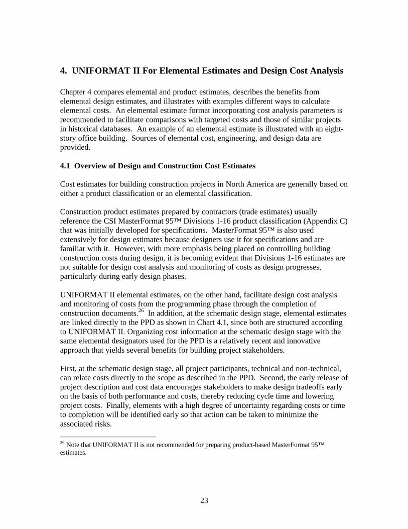
Chapter 4 compares elemental and product estimates, describes the benefits fromelemental design estimates, and illustrates with examples different ways to calculateelemental costs. An elemental estimate format incorporating cost analysis parameters isrecommended to facilitate comparisons with targeted costs and those of similar projectsin historical databases. An example of an elemental estimate is illustrated with an eight-story office building. Sources of elemental cost, engineering, and design data areprovided.
4.1 Overview of Design and Construction Cost Estimates
Cost estimates for building construction projects in North America are generally based oneither a product classification or an elemental classification.
Construction product estimates prepared by contractors (trade estimates) usuallyreference the CSI MasterFormat 95™ Divisions 1-16 product classification (Appendix C)that was initially developed for specifications. MasterFormat 95™ is also usedextensively for design estimates because designers use it for specifications and arefamiliar with it. However, with more emphasis being placed on controlling buildingconstruction costs during design, it is becoming evident that Divisions 1-16 estimates arenot suitable for design cost analysis and monitoring of costs as design progresses,particularly during early design phases.
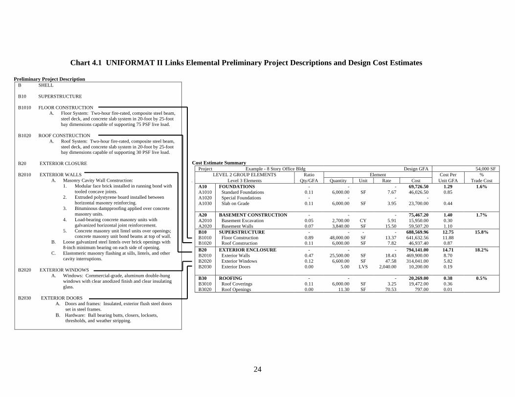
UNIFORMAT II elemental estimates, on the other hand, facilitate design cost analysisand monitoring of costs from the programming phase through the completion ofconstruction documents.26 In addition, at the schematic design stage, elemental estimatesare linked directly to the PPD as shown in Chart 4.1, since both are structured accordingto UNIFORMAT II. Organizing cost information at the schematic design stage with thesame elemental designators used for the PPD is a relatively recent and innovativeapproach that yields several benefits for building project stakeholders.
First, at the schematic design stage, all project participants, technical and non-technical,can relate costs directly to the scope as described in the PPD. Second, the early release ofproject description and cost data encourages stakeholders to make design tradeoffs earlyon the basis of both performance and costs, thereby reducing cycle time and loweringproject costs. Finally, elements with a high degree of uncertainty regarding costs or timeto completion will be identified early so that action can be taken to minimize theassociated risks.
26 Note that UNIFORMAT II is not recommended for preparing product-based MasterFormat 95™estimates.
24
Chart 4.1 UNIFORMAT II Links Elemental Preliminary Project Descriptions and Design Cost Estimates
Preliminary Project DescriptionB SHELL
B10 SUPERSTRUCTURE
B1010 FLOOR CONSTRUCTIONA. Floor System: Two-hour fire-rated, composite steel beam,
steel deck, and concrete slab system in 20-foot by 25-footbay dimensions capable of supporting 75 PSF live load.
B1020 ROOF CONSTRUCTIONA. Roof System: Two-hour fire-rated, composite steel beam,
steel deck, and concrete slab system in 20-foot by 25-footbay dimensions capable of supporting 30 PSF live load.
B20 EXTERIOR CLOSURE
B2010 EXTERIOR WALLSA. Masonry Cavity Wall Construction:
1. Modular face brick installed in running bond withtooled concave joints.
2. Extruded polystyrene board installed betweenhorizontal masonry reinforcing.
3. Bituminous dampproofing applied over concretemasonry units.
4. Load-bearing concrete masonry units withgalvanized horizontal joint reinforcement.
5. Concrete masonry unit lintel units over openings;concrete masonry unit bond beams at top of wall.
B. Loose galvanized steel lintels over brick openings with8-inch minimum bearing on each side of opening.
C. Elastomeric masonry flashing at sills, lintels, and othercavity interruptions.
B2020 EXTERIOR WINDOWSA. Windows: Commercial-grade, aluminum double-hung
windows with clear anodized finish and clear insulatingglass.
B2030 EXTERIOR DOORSA. Doors and frames: Insulated, exterior flush steel doors set in steel frames.B. Hardware: Ball bearing butts, closers, locksets, thresholds, and weather stripping.
Cost Estimate SummaryProject Example - 8 Story Office Bldg Design GFA 54,000 SF
LEVEL 2 GROUP ELEMENTS Ratio Element Cost Per %Level 3 Elements Qty/GFA Quantity Unit Rate Cost Unit GFA Trade Cost
A10A1010A1020A1030
FOUNDATIONS Standard Foundations Special Foundations Slab on Grade
-0.11
-0.11
-6,000.00
-6,000.00
SF
SF
-7.67
-3.95
69,726.5046,026.50
-23,700.00
1.290.85
0.44
1.6%
A20A2010A2020
BASEMENT CONSTRUCTION Basement Excavation Basement Walls
-0.050.07
-2,700.003,840.00
CYSF
-5.91
15.50
75,467.2015,950.0059,507.20
1.400.301.10
1.7%
B10B1010B1020
SUPERSTRUCTURE Floor Construction Roof Construction
-0.890.11
-48,000.00
6,000.00
-SFSF
-13.377.82
688,569.96641,632.56
46,937.40
12.7511.880.87
15.8%
B20B2010B2020B2030
EXTERIOR ENCLOSURE Exterior Walls Exterior Windows Exterior Doors
-0.470.120.00
-25,500.00
6,600.005.00
SFSF
LVS
-18.4347.58
2,040.00
794,141.00469,900.00314,041.00
10,200.00
14.718.705.820.19
18.2%
B30B3010B3020
ROOFING Roof Coverings Roof Openings
-0.110.00
-6,000.00
11.30SFSF
-3.25
70.53
20,269.0019,472.00
797.00
0.380.360.01
0.5%
25
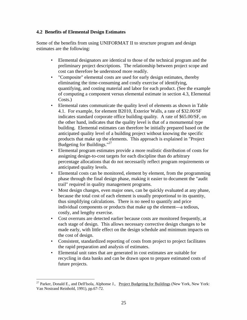
4.2 Benefits of Elemental Design Estimates
Some of the benefits from using UNIFORMAT II to structure program and designestimates are the following:
• Elemental designators are identical to those of the technical program and thepreliminary project descriptions. The relationship between project scope andcost can therefore be understood more readily.
• "Composite" elemental costs are used for early design estimates, therebyeliminating the time-consuming and costly exercise of identifying,quantifying, and costing material and labor for each product. (See the exampleof computing a component versus elemental estimate in section 4.3, ElementalCosts.)
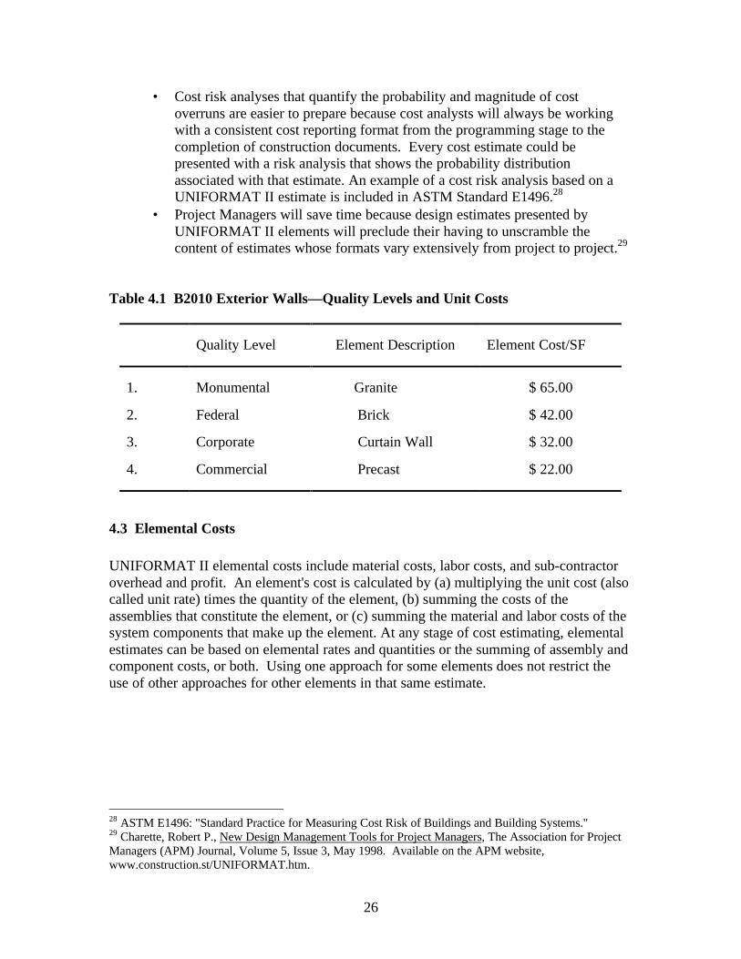
• Elemental rates communicate the quality level of elements as shown in Table4.1. For example, for element B2010, Exterior Walls, a rate of $32.00/SFindicates standard corporate office building quality. A rate of $65.00/SF, onthe other hand, indicates that the quality level is that of a monumental typebuilding. Elemental estimates can therefore be initially prepared based on theanticipated quality level of a building project without knowing the specificproducts that make up the elements. This approach is explained in "ProjectBudgeting for Buildings."27
• Elemental program estimates provide a more realistic distribution of costs forassigning design-to-cost targets for each discipline than do arbitrarypercentage allocations that do not necessarily reflect program requirements oranticipated quality levels.
• Elemental costs can be monitored, element by element, from the programmingphase through the final design phase, making it easier to document the "audittrail" required in quality management programs.
• Most design changes, even major ones, can be quickly evaluated at any phase,because the total cost of each element is usually proportional to its quantity,thus simplifying calculations. There is no need to quantify and priceindividual components or products that make up the element—a tedious,costly, and lengthy exercise.
• Cost overruns are detected earlier because costs are monitored frequently, ateach stage of design. This allows necessary corrective design changes to bemade early, with little effect on the design schedule and minimum impacts onthe cost of design.
• Consistent, standardized reporting of costs from project to project facilitatesthe rapid preparation and analysis of estimates.
• Elemental unit rates that are generated in cost estimates are suitable forrecycling in data banks and can be drawn upon to prepare estimated costs offuture projects.
27 Parker, Donald E., and Dell'Isola, Alphonse J., Project Budgeting for Buildings (New York, New York:Van Nostrand Reinhold, 1991), pp.67-72.
26
• Cost risk analyses that quantify the probability and magnitude of costoverruns are easier to prepare because cost analysts will always be workingwith a consistent cost reporting format from the programming stage to thecompletion of construction documents. Every cost estimate could bepresented with a risk analysis that shows the probability distributionassociated with that estimate. An example of a cost risk analysis based on aUNIFORMAT II estimate is included in ASTM Standard E1496.28
• Project Managers will save time because design estimates presented byUNIFORMAT II elements will preclude their having to unscramble thecontent of estimates whose formats vary extensively from project to project.29
Table 4.1 B2010 Exterior Walls—Quality Levels and Unit Costs
Quality Level Element Description Element Cost/SF
1. Monumental Granite $ 65.00
2. Federal Brick $ 42.00
3. Corporate Curtain Wall $ 32.00
4. Commercial Precast $ 22.00
4.3 Elemental Costs
UNIFORMAT II elemental costs include material costs, labor costs, and sub-contractoroverhead and profit. An element's cost is calculated by (a) multiplying the unit cost (alsocalled unit rate) times the quantity of the element, (b) summing the costs of theassemblies that constitute the element, or (c) summing the material and labor costs of thesystem components that make up the element. At any stage of cost estimating, elementalestimates can be based on elemental rates and quantities or the summing of assembly andcomponent costs, or both. Using one approach for some elements does not restrict theuse of other approaches for other elements in that same estimate.
28 ASTM E1496: "Standard Practice for Measuring Cost Risk of Buildings and Building Systems."29 Charette, Robert P., New Design Management Tools for Project Managers, The Association for ProjectManagers (APM) Journal, Volume 5, Issue 3, May 1998. Available on the APM website,www.construction.st/UNIFORMAT.htm.
27
4.3.1 Unit Rates and Quantities
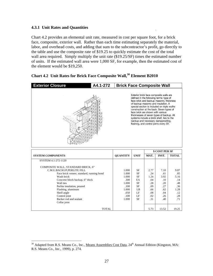
Chart 4.2 provides an elemental unit rate, measured in cost per square foot, for a brickface, composite, exterior wall. Rather than each time estimating separately the material,labor, and overhead costs, and adding that sum to the subcontractor’s profit, go directly tothe table and use the composite rate of $19.25 to quickly estimate the cost of the totalwall area required. Simply multiply the unit rate ($19.25/SF) times the estimated numberof units. If the estimated wall area were 1,000 SF, for example, then the estimated cost ofthe element would be $19,250.
Chart 4.2 Unit Rates for Brick Face Composite Wall,30 Element B2010
Exterior Closure A4.1-272 Brick Face Composite Wall
$ COST PER SF
SYSTEM COMPONENTS QUANTITY UNIT MAT. INST. TOTAL
SYSTEM 4.1-272-1120
COMPOSITE WALL, STANDARD BRICK, 6”C.M.U.BACKUP,PERLITE FILL
Face brick veneer, standard, running bondWash brickConcrete block backup, 6” thickWall tiesPerlite insulation, pouredFlashing, aluminumShelf angleControl jointBacker rod and sealantCollar joint
1.0001.0001.000 .3001.000 .1001.000 .050 .1001.000
SFSFSFEASFSF LBLFLFSF
2.77 .241.24 .04 .28 .09 .66 .08 .02 .31
7.10 .61 3.92 .10 .20 .27 .62 .04 .26 .40
9.87 .85 5.16 .14 .48 .36 1.28 .12 .28 .71
TOTAL 5.73 13.52 19.25
30 Adapted from R.S. Means Co., Inc., Means Assemblies Cost Data, 24th Annual Edition (Kingston, MA:R.S. Means Co., Inc., 1999), p. 274.
28
4.3.2 Assembly Costs
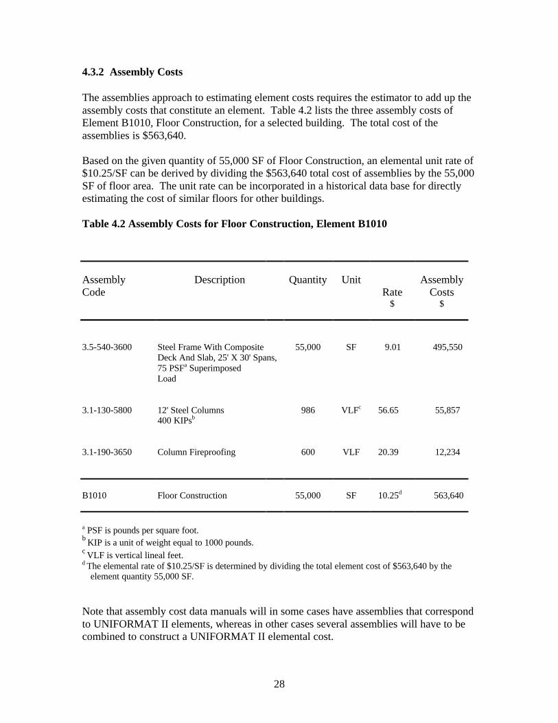
The assemblies approach to estimating element costs requires the estimator to add up theassembly costs that constitute an element. Table 4.2 lists the three assembly costs ofElement B1010, Floor Construction, for a selected building. The total cost of theassemblies is $563,640.
Based on the given quantity of 55,000 SF of Floor Construction, an elemental unit rate of$10.25/SF can be derived by dividing the $563,640 total cost of assemblies by the 55,000SF of floor area. The unit rate can be incorporated in a historical data base for directlyestimating the cost of similar floors for other buildings.
Table 4.2 Assembly Costs for Floor Construction, Element B1010
AssemblyCode
Description Quantity UnitRate
AssemblyCosts
$ $
3.5-540-3600 Steel Frame With CompositeDeck And Slab, 25' X 30' Spans,75 PSFa Superimposed
55,000 SF 9.01 495,550
Load
3.1-130-5800 12' Steel Columns400 KIPsb
986 VLFc 56.65 55,857
3.1-190-3650 Column Fireproofing 600 VLF 20.39 12,234
B1010 Floor Construction 55,000 SF 10.25d 563,640
a PSF is pounds per square foot.b KIP is a unit of weight equal to 1000 pounds.c VLF is vertical lineal feet.d The elemental rate of $10.25/SF is determined by dividing the total element cost of $563,640 by the
element quantity 55,000 SF.
Note that assembly cost data manuals will in some cases have assemblies that correspondto UNIFORMAT II elements, whereas in other cases several assemblies will have to becombined to construct a UNIFORMAT II elemental cost.
29
4.3.3 Component Costs
The component approach is similar to the assemblies approach for estimating elementalcosts, except that individual component costs are summed to estimate the cost of anelement. Chart 4.3 shows how the cost of a 100 MBH heat generation system iscalculated from the cost of its individual components, such as the boiler, piping, pumps,insulation, and chimney. The sum of the costs of components for this element is$7,576.90.
To calculate a unit rate for estimating costs of similar-sized heat generating systems,divide the $7,576.90 by the unit measure 100 MBH. This resulting elemental rate of$75.77 per MBH can be incorporated in a historical database for estimating future projectcosts.
4.3.4 Units of Measurement
Suitable units of measurement are needed for estimating elemental costs by multiplyingelemental rates times quantities. Furthermore, these units of measurement are anessential part of the historical database of unit rates that will be used in preparing futurebudgets and estimates. Examples of units of measurement and corresponding unit ratesare as follows:
• A1010, Standard Foundations, are measured in square feet of footprint area (FPA). Ifthe cost of element A1010 is $30,433 for an FPA of 6,000 SF, the unit rate is$5.07/SF of FPA.
• B3010, Roof Coverings, are measured in square feet of roof area. If the cost is$17,506 for a 6,000 SF roof, the rate is $2.92/SF of roof area.
• C1010, Partitions, are measured in terms of square feet area of partition area. If thecost of C1010 is $160,846 for a quantity of 28,979 SF, the unit rate is $5.55/SF ofpartition area.
• D2040, Rain Water Drainage, is measured in square feet of roof area. If the cost ofD2040 is $6,137 for a 6000 SF roof, the unit rate is $1.02/SF of roof area.
• D3030, Cooling Generation, is measured in tons of refrigeration (TR). If the cost ofD3030 is $137,200 for a 150 ton chilled water cooling system, the rate is $915/TR.
Cost data sources based on appropriate units of measurement are listed in Section 4.7.1.
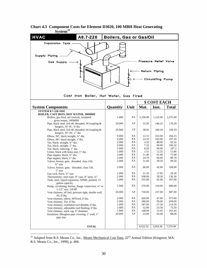
30
Chart 4.3 Component Costs for Element D3020, 100 MBH Heat GeneratingSystem31
HVACHVAC A8.7-220A8.7-220 Boilers, Gas or GasBoilers, Gas or Gas/OilOil
$ COST EACHSystem Components Quantity Unit Mat. Inst. Total
SYSTEM 8.7-220-1010BOILER, CAST IRON, HOT WATER, 100MBH
Boilers, gas fired, std controls, insulated, gross output, 100MBH
Pipe, black steel, Sch 40, threaded, W/coupling &hangers, 10’ 0C, ¾’dia
Pipe, black steel, Sch 40, threaded, W/coupling &hangers, 10’ OC, 1” dia
Elbow, 90°, black straight, ¾” dia.Elbow, 90°, black straight, 1”dia.Tee, black, straight, ¾” dia.Tee, black, straight, 1” dia.Tee, black, reducing, 1” dia.Union, black with brass seat, 1” dia.Pipe nipples, black, ¾” dia.Pipe nipples, black, 1” dia.Valves, bronze, gate, threaded, class 150,
¾” sizeValves, bronze, gate, threaded, class 150,
1” sizeGas cock, brass, ¾” sizeThermometer, stem type, 9” case, 8” stem, ¾”Tank, steel, liquid expansion, ASME, painted, 15
gallon capacityPump, circulating, bronze, flange connection, ¾” to
1-1/2” size, 1/8 HPVent chimney, all fuel, pressure tight, double wall,
SS, 6"dia.Vent chimney, elbow, 90ºfixed, 6"dia.Vent chimney, Tee, 6"dia.Vent chimney, ventilated roof thimble, 6"dia.Vent chimney, adjustable roof flashing, 6"dia.Vent chimney, stack cap. 6" diameterInsulation, fiberglass pipe covering, 1" wall, 1"
pipe size
1.000
20.000
20.000
9.000 6.000 2.000 2.000 2.000 1.000 2.000 2.000 2.000
2.000
1.000 2.000 1.000
1.000
20.000
2.000 2.000 1.000 1.000 1.000
20.000
EA
LF
LF
EAEAEAEAEAEAEAEAEA
EA
EAEAEA
EA
LF
EAEAEAEAEALF
1,350.00
31.95
38.92
12.1514.10
4.327.328.201.51
11.4014.7051.00
66.00
11.35108.00355.00
570.00
750.00
426.00280.00187.00
52.00148.00
23.60
1,125.00
146.25
160.18
252.00 183.00 88.00 99.00 99.00 12.35
61.0066.0039.50
42.00
17.95 28.30 42.00
119.00
237.00
47.00 59.00 27.50 23.50 15.45 64.40
2,475.00
178.20
199.10
264.15197.10
92.32106.32
107.213.8672.4080.7090.50
108.00
29.30136.30397.00
689.00
987.00
473.00339.00214.50
75.50163.45
88.00
TOTAL 4,522.52 3,054.38 7,576.90
31 Adapted from R.S. Means Co., Inc., Means Mechanical Cost Data, 22nd Annual Edition (Kingston, MA:R.S. Means Co., Inc., 1999), p. 466.
31
4.4 Cost Analysis Parameters
Cost analysis parameters developed in building and sitework elemental estimatesummaries facilitate analysis, control, and monitoring of costs from the programmingphase through design completion. Estimates using MasterFormat 95™ Divisions 1-16,based on products and materials, are less effective for these purposes.
Summaries of building elemental cost estimates (as shown in Table 4.3) contain thefollowing cost analysis parameters:
• Building construction cost (BCC) per unit GFA32 that includes all mark-ups.• Level 3 elemental costs per unit of measurement.• Level 3 elemental costs per unit of GFA.• Level 2 group elemental costs per unit of GFA.• Quantity of element per unit of GFA.
Corresponding parameters for the sitework cost summary are included in Table 4.4.
There are two primary reasons for using cost analysis parameters in evaluating estimates.The first is to analyze and monitor costs, element by element, as design progresses, toensure that costs are within the allocated budget and within the range of the costs ofcomparable historical projects with similar quality levels.
The second reason is to identify the likely source of budget overruns as early as possible.This facilitates making revisions to plans and specifications that may be required to meetthe budget with minimum impact on the design schedule and design cost.
4.5 Elemental Cost Estimate Summary Format and Case Illustration
This section proposes an elemental estimate summary format. It communicates costinformation in a concise, consistent manner to the client and project team members. Thesummary format helps them (1) understand the cost profile of the entire project,(2)analyze costs using analytic parameters, and (3) identify potential cost overruns earlyto initiate corrective action. We present a case illustration of an elemental estimate for an8-story office building. Cost data come from several Means Cost Manuals, primarily the1999 Means Assemblies Cost Data.33
32 Note that four of the five cost analysis parameters are based on Gross Floor Area (GFA). Thus, the GFAmust be determined in a consistent manner to produce reliable estimates and cost analysis parameters. Wehave chosen the AIA method of measurement for GFA in this report as described in AIA DocumentD101—The Architectural Area and Volume of Buildings (Washington, DC: The American Institute ofArchitects, 1980).33 R.S. Means Co., Inc., Means Assemblies Cost Data, 1999.
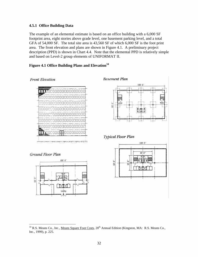
32
4.5.1 Office Building Data
The example of an elemental estimate is based on an office building with a 6,000 SFfootprint area, eight stories above grade level, one basement parking level, and a totalGFA of 54,000 SF. The total site area is 43,560 SF of which 6,000 SF is the foot printarea. The front elevation and plans are shown in Figure 4.1. A preliminary projectdescription (PPD) is shown in Chart 4.4. Note that the elemental PPD is relatively simpleand based on Level-2 group elements of UNIFORMAT II.
Figure 4.1 Office Building Plans and Elevation34
34 R.S. Means Co., Inc., Means Square Foot Costs, 20th Annual Edition (Kingston, MA: R.S. Means Co.,Inc., 1999), p. 225.
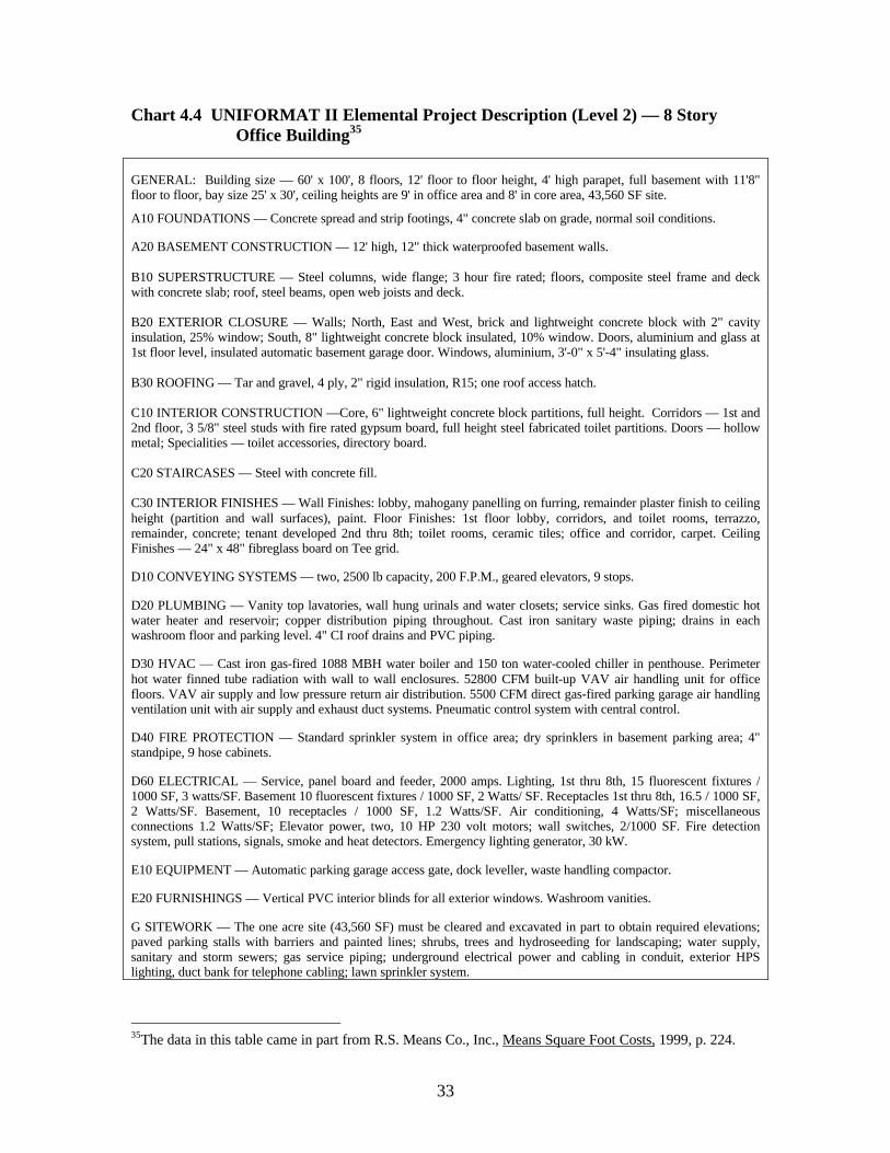
33
Chart 4.4 UNIFORMAT II Elemental Project Description (Level 2) — 8 StoryOffice Building35
GENERAL: Building size — 60' x 100', 8 floors, 12' floor to floor height, 4' high parapet, full basement with 11'8"floor to floor, bay size 25' x 30', ceiling heights are 9' in office area and 8' in core area, 43,560 SF site.
A10 FOUNDATIONS — Concrete spread and strip footings, 4" concrete slab on grade, normal soil conditions.
A20 BASEMENT CONSTRUCTION — 12' high, 12" thick waterproofed basement walls.
B10 SUPERSTRUCTURE — Steel columns, wide flange; 3 hour fire rated; floors, composite steel frame and deckwith concrete slab; roof, steel beams, open web joists and deck.
B20 EXTERIOR CLOSURE — Walls; North, East and West, brick and lightweight concrete block with 2" cavityinsulation, 25% window; South, 8" lightweight concrete block insulated, 10% window. Doors, aluminium and glass at1st floor level, insulated automatic basement garage door. Windows, aluminium, 3'-0" x 5'-4" insulating glass.
B30 ROOFING — Tar and gravel, 4 ply, 2" rigid insulation, R15; one roof access hatch.
C10 INTERIOR CONSTRUCTION —Core, 6" lightweight concrete block partitions, full height. Corridors — 1st and2nd floor, 3 5/8" steel studs with fire rated gypsum board, full height steel fabricated toilet partitions. Doors — hollowmetal; Specialities — toilet accessories, directory board.
C20 STAIRCASES — Steel with concrete fill.
C30 INTERIOR FINISHES — Wall Finishes: lobby, mahogany panelling on furring, remainder plaster finish to ceilingheight (partition and wall surfaces), paint. Floor Finishes: 1st floor lobby, corridors, and toilet rooms, terrazzo,remainder, concrete; tenant developed 2nd thru 8th; toilet rooms, ceramic tiles; office and corridor, carpet. CeilingFinishes — 24" x 48" fibreglass board on Tee grid.
D10 CONVEYING SYSTEMS — two, 2500 lb capacity, 200 F.P.M., geared elevators, 9 stops.
D20 PLUMBING — Vanity top lavatories, wall hung urinals and water closets; service sinks. Gas fired domestic hotwater heater and reservoir; copper distribution piping throughout. Cast iron sanitary waste piping; drains in eachwashroom floor and parking level. 4" CI roof drains and PVC piping.
D30 HVAC — Cast iron gas-fired 1088 MBH water boiler and 150 ton water-cooled chiller in penthouse. Perimeterhot water finned tube radiation with wall to wall enclosures. 52800 CFM built-up VAV air handling unit for officefloors. VAV air supply and low pressure return air distribution. 5500 CFM direct gas-fired parking garage air handlingventilation unit with air supply and exhaust duct systems. Pneumatic control system with central control.
D40 FIRE PROTECTION — Standard sprinkler system in office area; dry sprinklers in basement parking area; 4"standpipe, 9 hose cabinets.
D60 ELECTRICAL — Service, panel board and feeder, 2000 amps. Lighting, 1st thru 8th, 15 fluorescent fixtures /1000 SF, 3 watts/SF. Basement 10 fluorescent fixtures / 1000 SF, 2 Watts/ SF. Receptacles 1st thru 8th, 16.5 / 1000 SF,2 Watts/SF. Basement, 10 receptacles / 1000 SF, 1.2 Watts/SF. Air conditioning, 4 Watts/SF; miscellaneousconnections 1.2 Watts/SF; Elevator power, two, 10 HP 230 volt motors; wall switches, 2/1000 SF. Fire detectionsystem, pull stations, signals, smoke and heat detectors. Emergency lighting generator, 30 kW.
E10 EQUIPMENT — Automatic parking garage access gate, dock leveller, waste handling compactor.
E20 FURNISHINGS — Vertical PVC interior blinds for all exterior windows. Washroom vanities.
G SITEWORK — The one acre site (43,560 SF) must be cleared and excavated in part to obtain required elevations;paved parking stalls with barriers and painted lines; shrubs, trees and hydroseeding for landscaping; water supply,sanitary and storm sewers; gas service piping; underground electrical power and cabling in conduit, exterior HPSlighting, duct bank for telephone cabling; lawn sprinkler system.
35The data in this table came in part from R.S. Means Co., Inc., Means Square Foot Costs, 1999, p. 224.
34
4.5.2 Elemental Estimate Cost Summaries
A major advantage of the elemental estimate summaries presented here is that theyprovide cost analysis parameters and other information necessary to make a quick initialanalysis of costs. This can be done for most elements without having to refer to back-upinformation contained in the detail sheets.
The estimate cost summaries are presented in three tables36—Table 4.3 for the Building,Table 4.4 for the Sitework, and Table 4.5 for Total Construction Cost. Note that it isimportant that sitework costs be separated from building costs for meaningful costanalysis.
Table 4.3, UNIFORMAT II Elemental Cost Summary for Buildings, displays theestimated building costs only. It includes design and inflation allowances plus generalcontractor overhead and profit. The estimated building construction cost (BCC) for the8-story building is $5,461,571 ($101.14/SF of GFA).
Table 4.4, UNIFORMAT II Elemental Cost Summary for Sitework, displays estimatedcosts for sitework only. It too includes design and inflation allowances, plus the generalcontractor overhead and profit. The estimated sitework construction cost (SCC) is$236,895 ($6.31/SF of NSA or net site area).
Table 4.5, Total Construction Cost Summary, lists Level 3 elemental costs without designallowances, design allowances, overhead and profit, and inflation allowances for a totalconstruction cost (TCC) of $5,698,466.
4.5.3 Allowances, Overhead, and Profit
Construction cost summaries include mark-ups for (1) design allowances (contingencies),(2) the general contractor's overhead and profit (OH&P), and (3) inflation allowances.Incorporating these mark-ups in a consistent manner within UNIFORMAT II estimatesfacilitates meaningful comparisons of estimated costs from different projects anddifferent sources.
In Tables 4.3 (buildings) and 4.4 (sitework), all mark-ups are shown with "Z"designators. Note that these designators are not incorporated in the ASTM E1557standard because E1557 is a classification of building elements only, and not anestimating standard. The "Z" designators in the estimate summaries are the following:
• Design Allowances — Z10 (buildings), Z50(sitework)
36 The estimate cost summary format proposed in this report is incorporated in software available from G/CEMUNI, Inc., www.gcei.ca The three cost summary tables in this report were produced using thatsoftware.
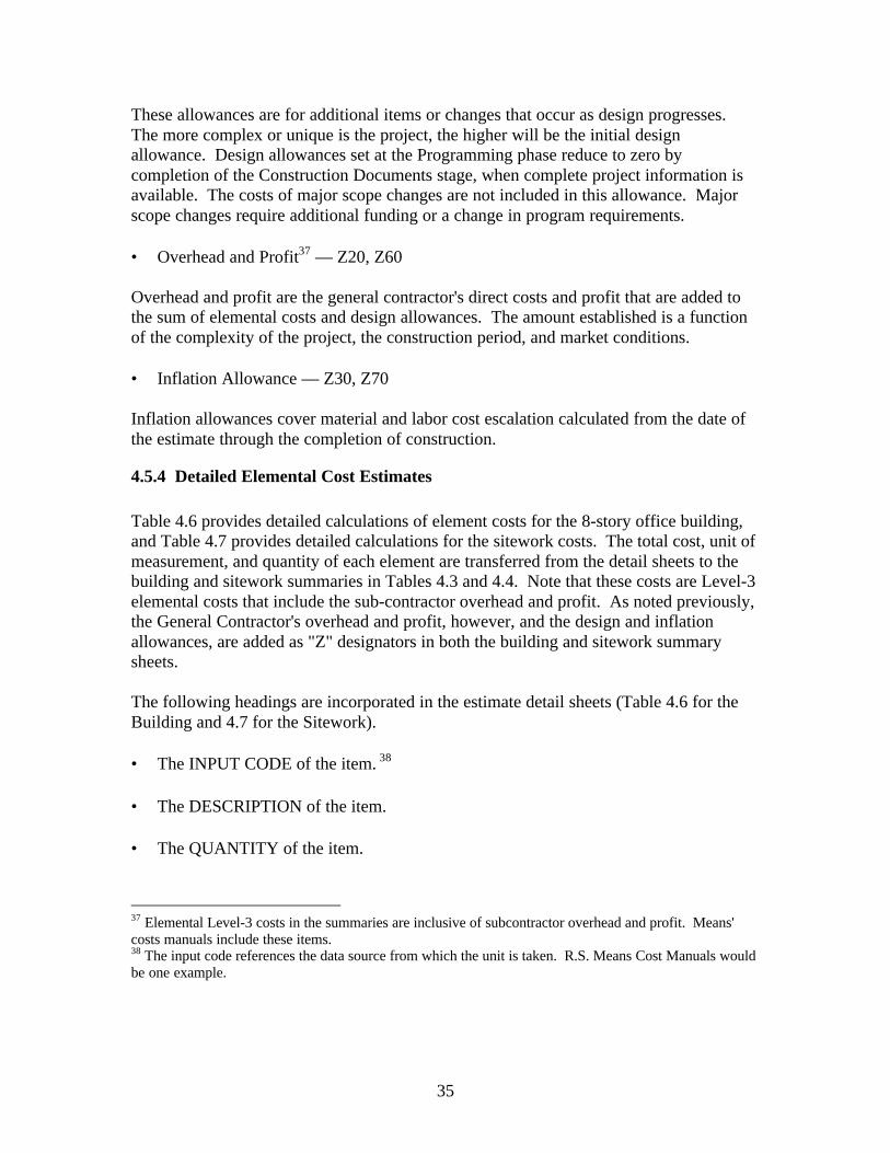
35
These allowances are for additional items or changes that occur as design progresses.The more complex or unique is the project, the higher will be the initial designallowance. Design allowances set at the Programming phase reduce to zero bycompletion of the Construction Documents stage, when complete project information isavailable. The costs of major scope changes are not included in this allowance. Majorscope changes require additional funding or a change in program requirements.
• Overhead and Profit37 — Z20, Z60
Overhead and profit are the general contractor's direct costs and profit that are added tothe sum of elemental costs and design allowances. The amount established is a functionof the complexity of the project, the construction period, and market conditions.
• Inflation Allowance — Z30, Z70
Inflation allowances cover material and labor cost escalation calculated from the date ofthe estimate through the completion of construction.
4.5.4 Detailed Elemental Cost Estimates
Table 4.6 provides detailed calculations of element costs for the 8-story office building,and Table 4.7 provides detailed calculations for the sitework costs. The total cost, unit ofmeasurement, and quantity of each element are transferred from the detail sheets to thebuilding and sitework summaries in Tables 4.3 and 4.4. Note that these costs are Level-3elemental costs that include the sub-contractor overhead and profit. As noted previously,the General Contractor's overhead and profit, however, and the design and inflationallowances, are added as "Z" designators in both the building and sitework summarysheets.
The following headings are incorporated in the estimate detail sheets (Table 4.6 for theBuilding and 4.7 for the Sitework).
• The INPUT CODE of the item. 38
• The DESCRIPTION of the item.
• The QUANTITY of the item.
37 Elemental Level-3 costs in the summaries are inclusive of subcontractor overhead and profit. Means'costs manuals include these items.38 The input code references the data source from which the unit is taken. R.S. Means Cost Manuals wouldbe one example.
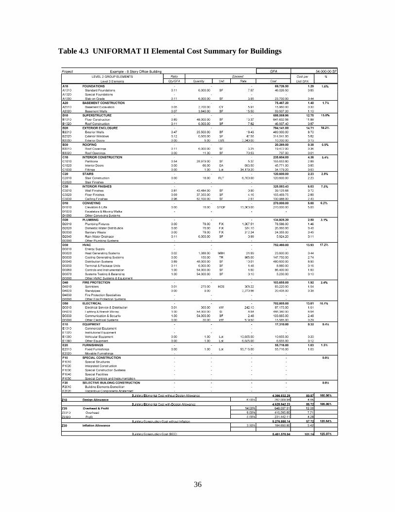
36
Table 4.3 UNIFORMAT II Elemental Cost Summary for Buildings
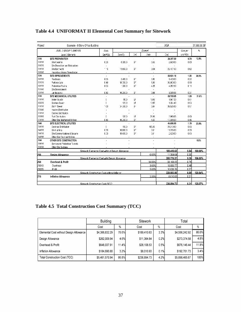
37
Table 4.4 UNIFORMAT II Elemental Cost Summary for Sitework
Table 4.5 Total Construction Cost Summary (TCC)
38
Table 4.6 Detailed Elemental Cost Estimates for Buildings
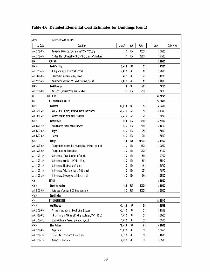
39
Table 4.6 Detailed Elemental Cost Estimates for Buildings (cont.)
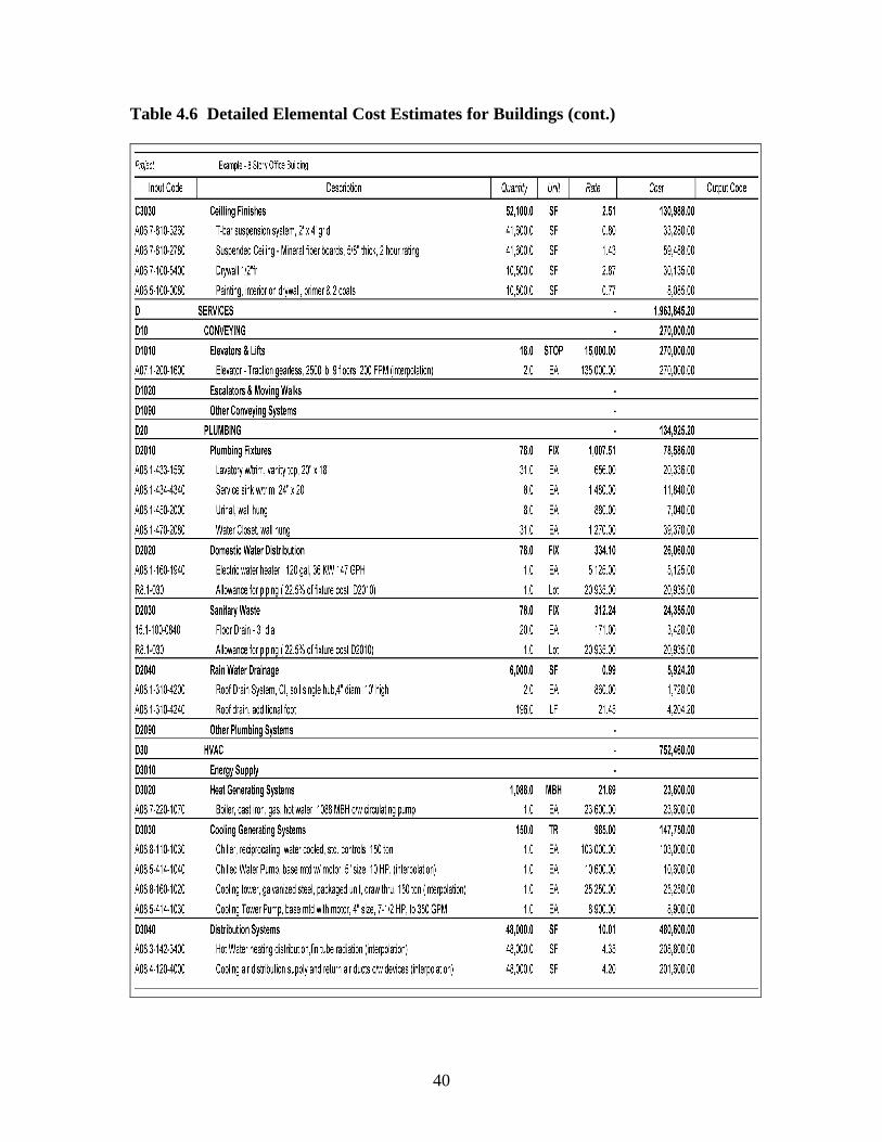
40
Table 4.6 Detailed Elemental Cost Estimates for Buildings (cont.)
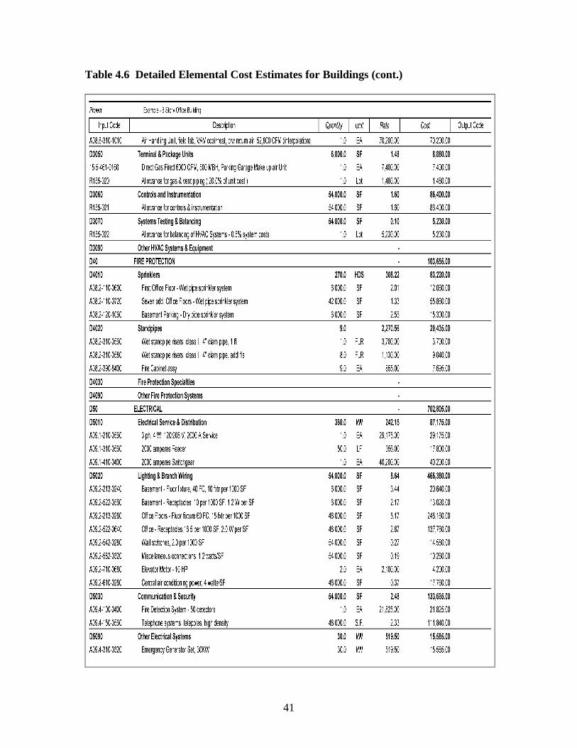
41
Table 4.6 Detailed Elemental Cost Estimates for Buildings (cont.)
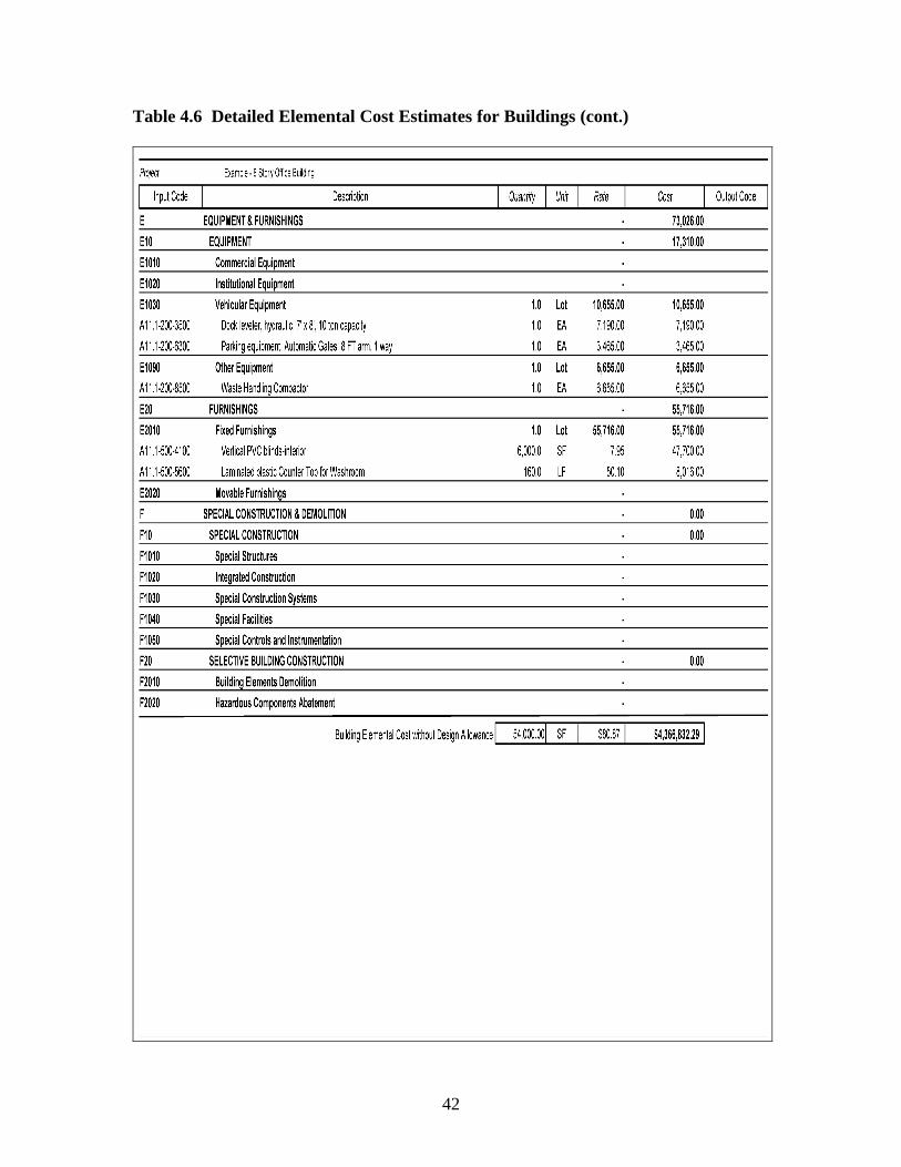
42
Table 4.6 Detailed Elemental Cost Estimates for Buildings (cont.)
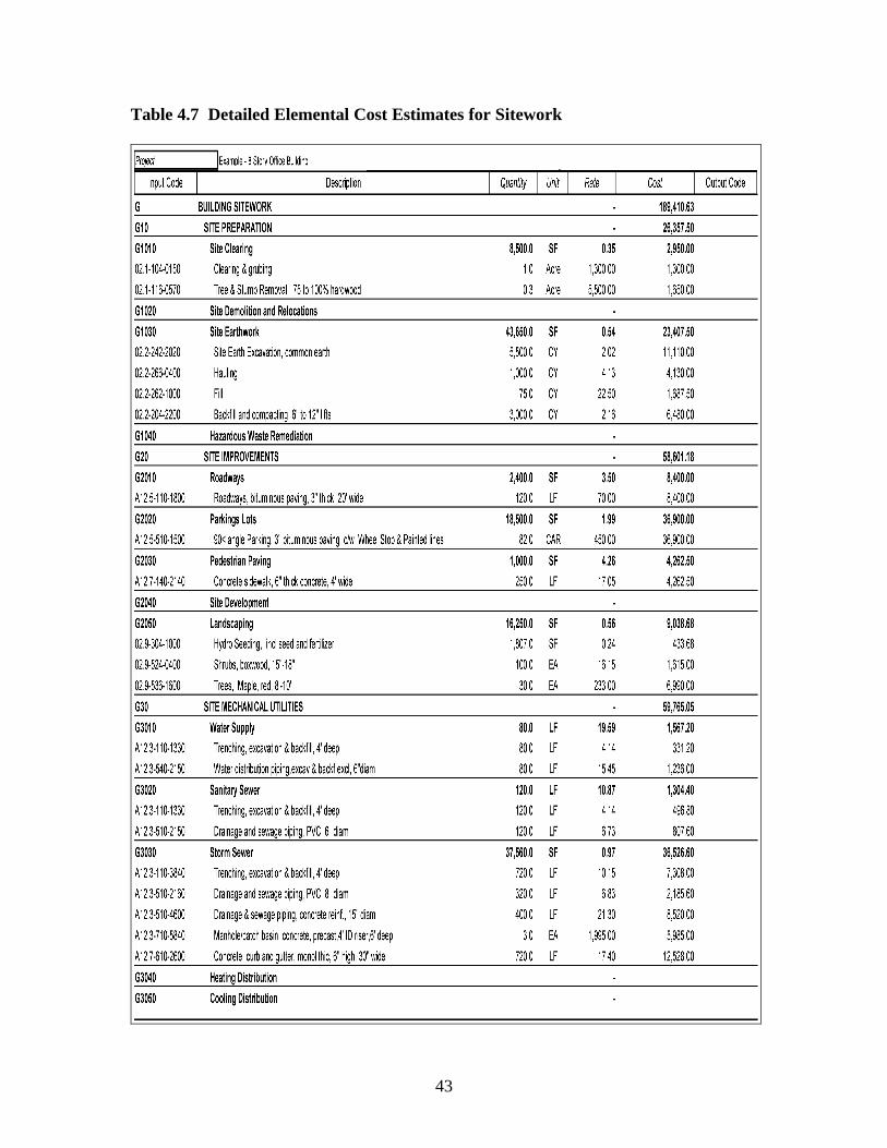
43
Table 4.7 Detailed Elemental Cost Estimates for Sitework
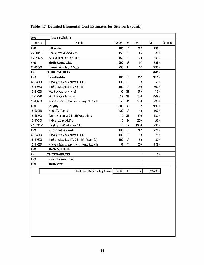
44
Table 4.7 Detailed Elemental Cost Estimates for Sitework (cont.)
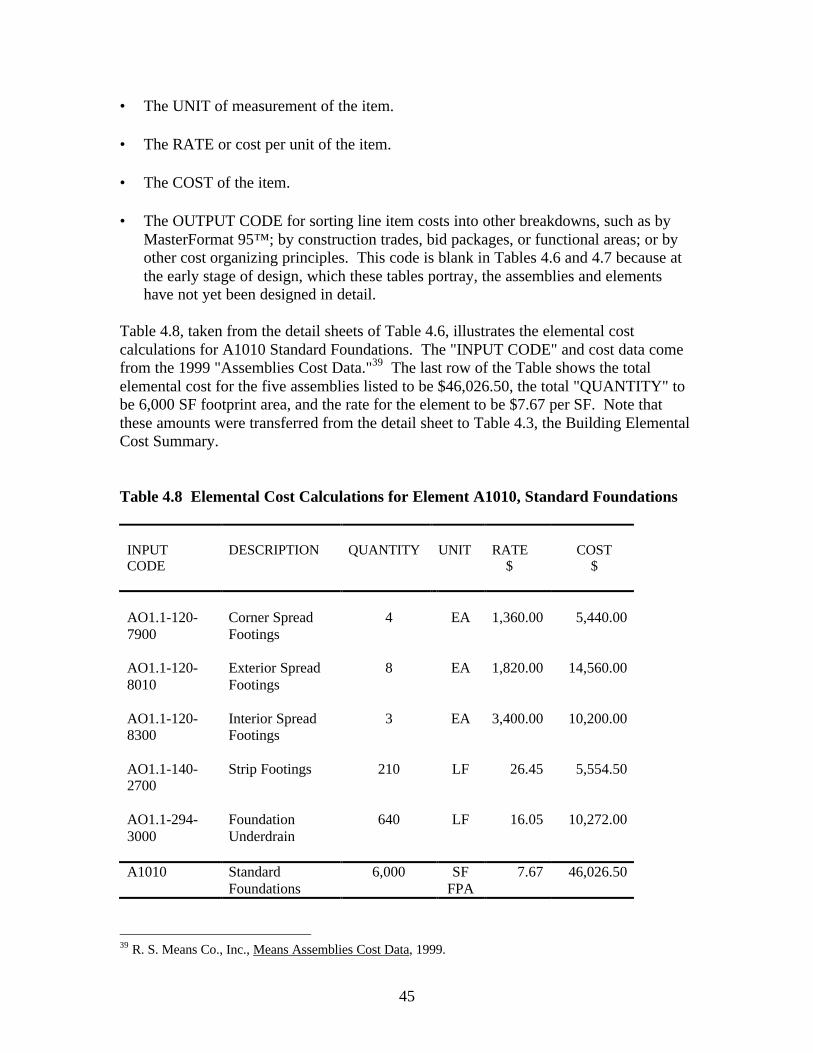
45
• The UNIT of measurement of the item.
• The RATE or cost per unit of the item.
• The COST of the item.
• The OUTPUT CODE for sorting line item costs into other breakdowns, such as byMasterFormat 95™; by construction trades, bid packages, or functional areas; or byother cost organizing principles. This code is blank in Tables 4.6 and 4.7 because atthe early stage of design, which these tables portray, the assemblies and elementshave not yet been designed in detail.
Table 4.8, taken from the detail sheets of Table 4.6, illustrates the elemental costcalculations for A1010 Standard Foundations. The "INPUT CODE" and cost data comefrom the 1999 "Assemblies Cost Data."39 The last row of the Table shows the totalelemental cost for the five assemblies listed to be $46,026.50, the total "QUANTITY" tobe 6,000 SF footprint area, and the rate for the element to be $7.67 per SF. Note thatthese amounts were transferred from the detail sheet to Table 4.3, the Building ElementalCost Summary.
Table 4.8 Elemental Cost Calculations for Element A1010, Standard Foundations
INPUTCODE
DESCRIPTION QUANTITY UNIT RATE $
COST $
AO1.1-120-7900
Corner SpreadFootings
4 EA 1,360.00 5,440.00
AO1.1-120-8010
Exterior SpreadFootings
8 EA 1,820.00 14,560.00
AO1.1-120-8300
Interior SpreadFootings
3 EA 3,400.00 10,200.00
AO1.1-140-2700
Strip Footings 210 LF 26.45 5,554.50
AO1.1-294-3000
FoundationUnderdrain
640 LF 16.05 10,272.00
A1010 StandardFoundations
6,000 SFFPA
7.67 46,026.50
39 R. S. Means Co., Inc., Means Assemblies Cost Data, 1999.
46
4.6 Converting UNIFORMAT II Estimates to MasterFormat 95TM
Elemental formats can be tied to product formats. For example, the elements of theoriginal UNIFORMAT have been related to the CSI MasterFormatTM for a specificdesign, as shown in Chart 4.5. It is drawn from Chapter B5, "Design and ConstructionCost Management," of the American Institute of Architects Handbook of ProfessionalPractice (1984).40 This mapping of one format to the other is useful in converting pre-bidelemental estimates to MasterFormat 95™ Divisions 1-16, and from there to the tradecosts of the project. A publication41 that lists product and material codes for elements isavailable to facilitate this conversion.
4.7 Sources of Elemental Cost, Engineering, and Design Data
4.7.1 Elemental Cost Data
Elemental cost data structured according to UNIFORMAT or UNIFORMAT II isavailable in the following publications:
• Means Assemblies Cost Data, 24th Annual Edition, 1999, R. S. Means, Co. Inc.,Kingston, MA
• Means Facilities Maintenance and Repair Cost Data, 7th Annual Edition, 1999, R. S.Means Co. Inc., Kingston, MA
• The Assemblies Sections of the following Annual Means Publications− Means 1999 Electrical Cost Data− Means 1999 Interior Cost Data− Means 1999 Mechanical Cost Data− Means 1999 Plumbing Cost Data− Means 1999 Residential Cost Data− Means 1999 Sitework and Landscape Cost Data− Means 1999 Square Foot Costs− Hanscomb's 1999 Yardsticks for Costing (Composite Unit Rate Section—
Canadian Institute of Quantity Surveyors Format)• Dell'Isola and Kirk, Life-Cycle Costing for Design Professionals42
• The Whitestone Building Maintenance and Repair Cost Reference: 199943
40 Table 6.1 also appeared in General Services Administration Handbook PBS P 3440.5, Project EstimatingRequirements, August 24, 1981. Note that it is based on UNIFORMAT — not UNIFORMAT II.41 Construction Specifications Institute, UniFormatTM: A Uniform Classification of Construction Systemsand Assemblies (Alexandria, VA: The Construction Specifications Institute, 1998 Edition).42 Dell'Isola, A.J. and Kirk, S.J., Life Cycle Costing for Design Professionals—2nd Edition (New York, NY:McGraw-Hill, Inc., 1995).43 Whitestone Research, The Whitestone Building Maintenance and Repair Cost Reference (Santa Barbara,CA: Whitestone Research Corporation, 1999).
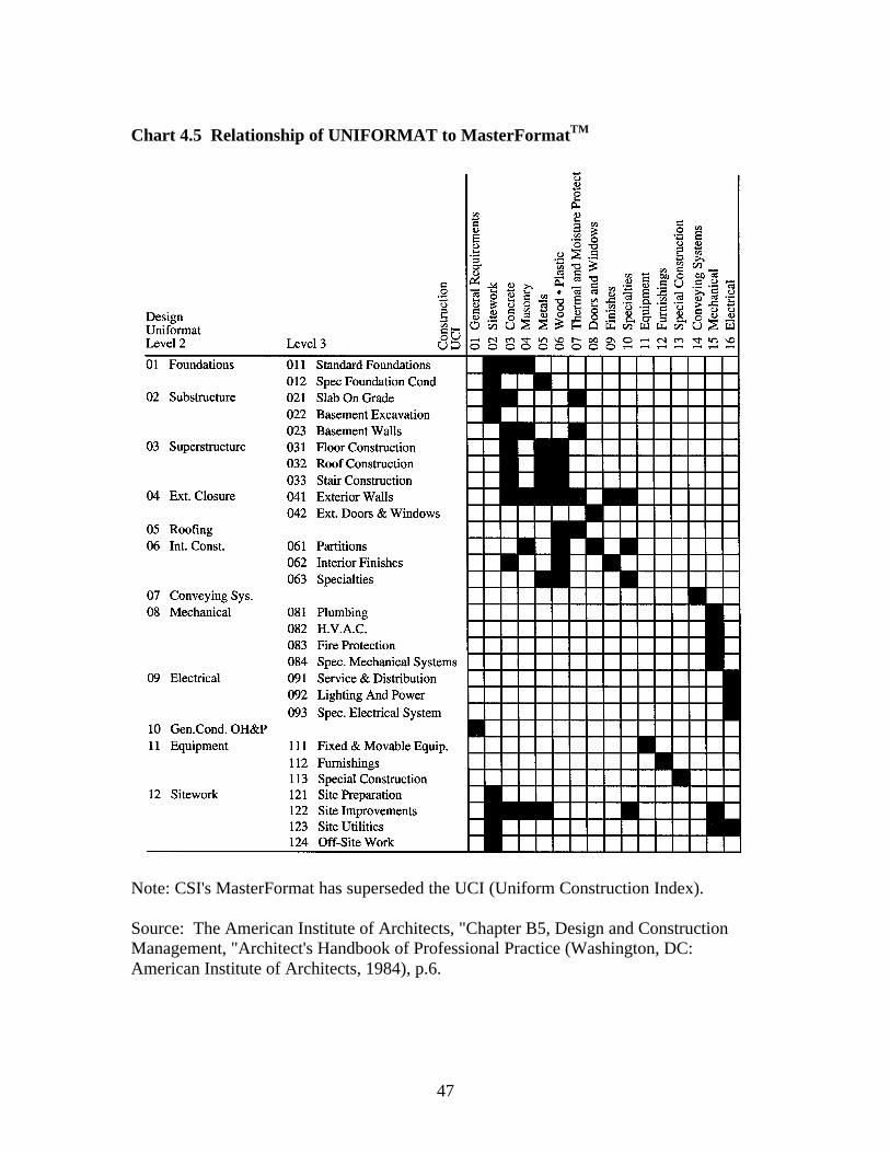
47
Chart 4.5 Relationship of UNIFORMAT to MasterFormatTM
Note: CSI's MasterFormat has superseded the UCI (Uniform Construction Index).
Source: The American Institute of Architects, "Chapter B5, Design and ConstructionManagement, "Architect's Handbook of Professional Practice (Washington, DC:American Institute of Architects, 1984), p.6.
48
4.7.2 Engineering and Design Data
The following publications have engineering and design data structured according toUNIFORMAT or UNIFORMAT II.
• Cox and Horsley, Square Foot Estimating Methods.44
• Killingsworth, Cost Control in Building Design.45
• Means Assemblies Cost Data, Reference Section, 24th Annual Edition 1999, R.S.Means Co. Inc., Kingston, MA.
• Means Building Construction Cost Data, Reference Section, 57th Annual Edition1997, R.S. Means Co. Inc., Kingston, MA.
• Means Graphic Construction Standards, 1986, R.S. Means Co., Inc., Kingston, MA
• McGraw-Hill Time Saver Standards for Architectural Design, 7th ed., McGraw Hill,1997.
44 Cox, B.J. and Horsley, William, Square Foot Estimating Methods, 2nd Edition (Kingston, MA: R.S.Means Co., Inc., 1995).45 Killingsworth, Roger, Cost Control in Building Design (Kingston, MA: R.S. Means Co., Inc., 1988).
49
5. Recommended Level-4 Classification
ASTM's UNIFORMAT II incorporates three hierarchical levels. Some users ofUNIFORMAT have felt the need, however, for a fourth level of sub-elements. We usedthe lists of exclusions and inclusions in Appendix B associated with Level-3 descriptionsas a starting point to construct and formalize a suggested UNIFORMAT II Level-4breakdown. The Level-4 sub-elements are presented in Charts 5.1 for buildings and 5.2for sitework.
The Level-4 sub-elements are based in part on the original UNIFORMAT Level-4 sub-elements46 and the Tri-Services TRACES Work Breakdown Structure (WBS).Standardizing Level 4 has the following advantages.
Better Cost Data—Increasing the number of designators in the classification by adding anadditional level facilitates the development of more comprehensive databases, therebyproviding more information for cost estimating and cost control. For example, thisbroader framework of classification will help estimators to prepare more accurate anddetailed estimates, and reduce the magnitude of allowances and contingencies. Projectdescriptions can be more specific with the addition of the recommended 274 designatorsfor the building and 128 for the sitework.
Consistency—Expansion of UNIFORMAT II to 4 levels ensures consistency as to whereitems belong. For example, without Level 4, there is ambiguity as to whether the interiorfinish to exterior walls belongs to B2010 (Exterior Walls) or C3010 (Wall Finishes).Knowing that an item consistently goes to a specific element category will reduce laborcosts of estimating and improve coordination among users of UNIFORMAT II.
More Comprehensive Historical Database—Having a deeper hierarchy of data for a givenstock of buildings will strengthen the validation of current cost estimates against the costsof similar buildings constructed in the past.
Interface with MasterFormat 95™—Level-3 elements are general in character. A moredetailed level of description is needed to relate UNIFORMAT II elements toMasterFormat 95™. For example, in the case of B3010, Roof Coverings, Level 4 wouldcategorize several components that would map directly to MasterFormat 95™, includingthe membrane, vapor retarder, and insulation.
Preliminary Construction Schedules—Preliminary elemental construction schedules canbe prepared in more detail during early design because construction tasks can be definedin more detail with Level-4 sub-elements. The more detailed schedule is useful inestablishing cash flow requirements for the project since construction costs can beestablished for sub-elements of the project.
46 Hanscomb Associates, Inc., Automated Cost Control & Estimating System (Washington, DC: GeneralServices Administration, 1975).
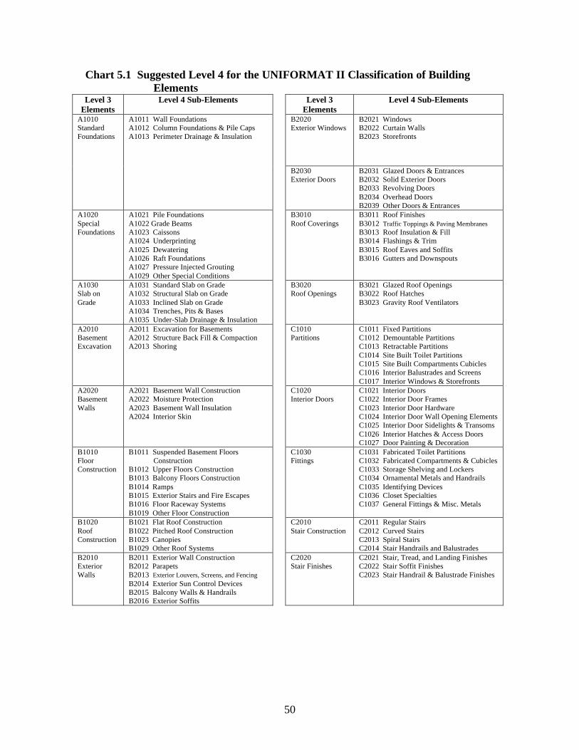
50
Chart 5.1 Suggested Level 4 for the UNIFORMAT II Classification of BuildingElements
Level 3Elements
Level 4 Sub-Elements Level 3Elements
Level 4 Sub-Elements
A1010StandardFoundations
A1011 Wall FoundationsA1012 Column Foundations & Pile CapsA1013 Perimeter Drainage & Insulation
B2020Exterior Windows
B2021 WindowsB2022 Curtain WallsB2023 Storefronts
B2030Exterior Doors
B2031 Glazed Doors & EntrancesB2032 Solid Exterior DoorsB2033 Revolving DoorsB2034 Overhead DoorsB2039 Other Doors & Entrances
A1020SpecialFoundations
A1021 Pile FoundationsA1022 Grade BeamsA1023 CaissonsA1024 UnderprintingA1025 DewateringA1026 Raft FoundationsA1027 Pressure Injected GroutingA1029 Other Special Conditions
B3010Roof Coverings
B3011 Roof FinishesB3012 Traffic Toppings & Paving MembranesB3013 Roof Insulation & FillB3014 Flashings & TrimB3015 Roof Eaves and SoffitsB3016 Gutters and Downspouts
A1030Slab onGrade
A1031 Standard Slab on GradeA1032 Structural Slab on GradeA1033 Inclined Slab on GradeA1034 Trenches, Pits & BasesA1035 Under-Slab Drainage & Insulation
B3020Roof Openings
B3021 Glazed Roof OpeningsB3022 Roof HatchesB3023 Gravity Roof Ventilators
A2010BasementExcavation
A2011 Excavation for BasementsA2012 Structure Back Fill & CompactionA2013 Shoring
C1010Partitions
C1011 Fixed PartitionsC1012 Demountable PartitionsC1013 Retractable PartitionsC1014 Site Built Toilet PartitionsC1015 Site Built Compartments CubiclesC1016 Interior Balustrades and ScreensC1017 Interior Windows & Storefronts
A2020BasementWalls
A2021 Basement Wall ConstructionA2022 Moisture ProtectionA2023 Basement Wall InsulationA2024 Interior Skin
C1020Interior Doors
C1021 Interior DoorsC1022 Interior Door FramesC1023 Interior Door HardwareC1024 Interior Door Wall Opening ElementsC1025 Interior Door Sidelights & TransomsC1026 Interior Hatches & Access DoorsC1027 Door Painting & Decoration
B1010FloorConstruction
B1011 Suspended Basement FloorsConstruction
B1012 Upper Floors ConstructionB1013 Balcony Floors ConstructionB1014 RampsB1015 Exterior Stairs and Fire EscapesB1016 Floor Raceway SystemsB1019 Other Floor Construction
C1030Fittings
C1031 Fabricated Toilet PartitionsC1032 Fabricated Compartments & CubiclesC1033 Storage Shelving and LockersC1034 Ornamental Metals and HandrailsC1035 Identifying DevicesC1036 Closet SpecialtiesC1037 General Fittings & Misc. Metals
B1020RoofConstruction
B1021 Flat Roof ConstructionB1022 Pitched Roof ConstructionB1023 CanopiesB1029 Other Roof Systems
C2010Stair Construction
C2011 Regular StairsC2012 Curved StairsC2013 Spiral StairsC2014 Stair Handrails and Balustrades
B2010ExteriorWalls
B2011 Exterior Wall ConstructionB2012 ParapetsB2013 Exterior Louvers, Screens, and FencingB2014 Exterior Sun Control DevicesB2015 Balcony Walls & HandrailsB2016 Exterior Soffits
C2020Stair Finishes
C2021 Stair, Tread, and Landing FinishesC2022 Stair Soffit FinishesC2023 Stair Handrail & Balustrade Finishes
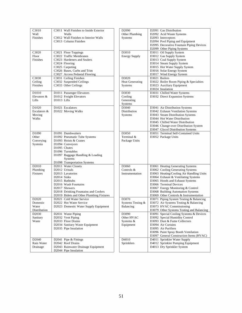
51
C3010WallFinishes
C3011 Wall Finishes to Inside Exterior WallsC3012 Wall Finishes to Interior WallsC3013 Column Finishes
D2090Other PlumbingSystems
D2091 Gas DistributionD2092 Acid Waste SystemsD2093 InterceptorsD2094 Pool Piping and EquipmentD2095 Decorative Fountain Piping DevicesD2099 Other Piping Systems
C3020FloorFinishes
C3021 Floor ToppingsC3022 Traffic MembranesC3023 Hardeners and SealersC3024 FlooringC3025 CarpetingC3026 Bases, Curbs and TrimC3027 Access Pedastal Flooring
D3010Energy Supply
D3011 Oil Supply SystemD3012 Gas Supply SystemD3013 Coal Supply SystemD3014 Steam Supply SystemD3015 Hot Water Supply SystemD3016 Solar Energy SystemD3017 Wind Energy System
C3030CeilingFinishes
C3031 Ceiling FinishesC3032 Suspended CeilingsC3033 Other Ceilings
D3020Heat GeneratingSystems
D3021 BoilersD3022 Boiler Room Piping & SpecialtiesD3023 Auxiliary EquipmentD3024 Insulation
D1010Elevators &Lifts
D1011 Passenger ElevatorsD1012 Freight ElevatorsD1013 Lifts
D3030CoolingGeneratingSystems
D3031 Chilled Water SystemsD3032 Direct Expansion Systems
D1020Escalators &MovingWalks
D1021 EscalatorsD1022 Moving Walks
D3040DistributionSystems
D3041 Air Distribution SystemsD3042 Exhaust Ventilation SystemsD3043 Steam Distribution SystemsD3044 Hot Water DistributionD3045 Chilled Water DistributionD3046 Change-over Distribution SystemD3047 Glycol Distribution Systems
D1090OtherConveyingSystems
D1091 DumbwaitersD1092 Pneumatic Tube SystemsD1093 Hoists & CranesD1094 ConveyorsD1095 ChutesD1096 TurntablesD1097 Baggage Handling & Loading SystemsD1098 Transportation Systems
D3050Terminal &Package Units
D3051 Terminal Self-Contained UnitsD3052 Package Units
D2010PlumbingFixtures
D2011 Water ClosetsD2012 UrinalsD2013 LavatoriesD2014 SinksD2015 BathtubsD2016 Wash FountainsD2017 ShowersD2018 Drinking Fountains and CoolersD2019 Bidets and Other Plumbing Fixtures
D3060Controls &Instrumentation
D3061 Heating Generating SystemsD3062 Cooling Generating SystemsD3063 Heating/Cooling Air Handling UnitsD3064 Exhaust & Ventilating SystemsD3065 Hoods and Exhaust SystemsD3066 Terminal DevicesD3067 Energy Monitoring & ControlD3068 Building Automation SystemsD3069 Other Controls & Instrumentation
D2020DomesticWaterDistribution
D2021 Cold Water ServiceD2022 Hot Water ServiceD2023 Domestic Water Supply Equipment
D3070Systems Testing &Balancing
D3071 Piping System Testing & BalancingD3072 Air Systems Testing & BalancingD3073 HVAC CommissioningD3079 Other Systems Testing and Balancing
D2030SanitaryWaste
D2031 Waste PipingD2032 Vent PipingD2033 Floor DrainsD2034 Sanitary Waste EquipmentD2035 Pipe Insulation
D3090Other HVACSystems &Equipment
D3091 Special Cooling Systems & DevicesD3092 Special Humidity ControlD3093 Dust & Fume CollectorsD3094 Air CurtainsD3095 Air PurifiersD3096 Paint Spray Booth VentilationD3097 General Construction Items (HVAC)
D2040Rain WaterDrainage
D2041 Pipe & FittingsD2042 Roof DrainsD2043 Rainwater Drainage EquipmentD2044 Pipe Insulation
D4010Sprinklers
D4011 Sprinkler Water SupplyD4012 Sprinkler Pumping EquipmentD4013 Dry Sprinkler System
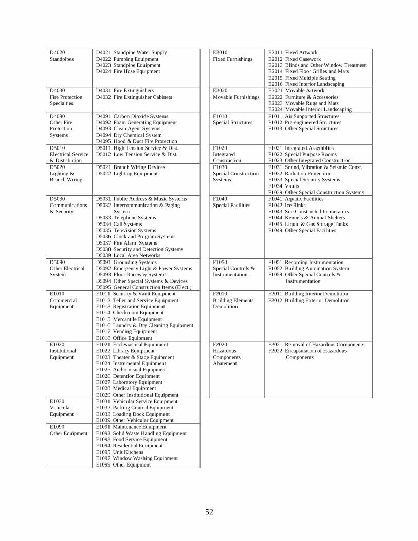
52
D4020Standpipes
D4021 Standpipe Water SupplyD4022 Pumping EquipmentD4023 Standpipe EquipmentD4024 Fire Hose Equipment
E2010Fixed Furnishings
E2011 Fixed ArtworkE2012 Fixed CaseworkE2013 Blinds and Other Window TreatmentE2014 Fixed Floor Grilles and MatsE2015 Fixed Multiple SeatingE2016 Fixed Interior Landscaping
D4030Fire ProtectionSpecialties
D4031 Fire ExtinguishersD4032 Fire Extinguisher Cabinets
E2020Movable Furnishings
E2021 Movable ArtworkE2022 Furniture & AccessoriesE2023 Movable Rugs and MatsE2024 Movable Interior Landscaping
D4090Other FireProtectionSystems
D4091 Carbon Dioxide SystemsD4092 Foam Generating EquipmentD4093 Clean Agent SystemsD4094 Dry Chemical SystemD4095 Hood & Duct Fire Protection
F1010Special Structures
F1011 Air Supported StructuresF1012 Pre-engineered StructuresF1013 Other Special Structures
D5010Electrical Service& Distribution
D5011 High Tension Service & Dist.D5012 Low Tension Service & Dist.
F1020IntegratedConstruction
F1021 Integrated AssembliesF1022 Special Purpose RoomsF1023 Other Integrated Construction
D5020Lighting &Branch Wiring
D5021 Branch Wiring DevicesD5022 Lighting Equipment
F1030Special ConstructionSystems
F1031 Sound, Vibration & Seismic Const.F1032 Radiation ProtectionF1033 Special Security SystemsF1034 VaultsF1039 Other Special Construction Systems
D5030Communications& Security
D5031 Public Address & Music SystemsD5032 Intercommunication & Paging SystemD5033 Telephone SystemsD5034 Call SystemsD5035 Television SystemsD5036 Clock and Program SystemsD5037 Fire Alarm SystemsD5038 Security and Detection SystemsD5039 Local Area Networks
F1040Special Facilities
F1041 Aquatic FacilitiesF1042 Ice RinksF1043 Site Constructed IncineratorsF1044 Kennels & Animal SheltersF1045 Liquid & Gas Storage TanksF1049 Other Special Facilities
D5090Other ElectricalSystem
D5091 Grounding SystemsD5092 Emergency Light & Power SystemsD5093 Floor Raceway SystemsD5094 Other Special Systems & DevicesD5095 General Construction Items (Elect.)
F1050Special Controls &Instrumentation
F1051 Recording InstrumentationF1052 Building Automation SystemF1059 Other Special Controls & Instrumentation
E1010CommercialEquipment
E1011 Security & Vault EquipmentE1012 Teller and Service EquipmentE1013 Registration EquipmentE1014 Checkroom EquipmentE1015 Mercantile EquipmentE1016 Laundry & Dry Cleaning EquipmentE1017 Vending EquipmentE1018 Office Equipment
F2010Building ElementsDemolition
F2011 Building Interior DemolitionF2012 Building Exterior Demolition
E1020InstitutionalEquipment
E1021 Ecclesiastical EquipmentE1022 Library EquipmentE1023 Theater & Stage EquipmentE1024 Instrumental EquipmentE1025 Audio-visual EquipmentE1026 Detention EquipmentE1027 Laboratory EquipmentE1028 Medical EquipmentE1029 Other Institutional Equipment
F2020HazardousComponentsAbatement
F2021 Removal of Hazardous ComponentsF2022 Encapsulation of Hazardous Components
E1030VehicularEquipment
E1031 Vehicular Service EquipmentE1032 Parking Control EquipmentE1033 Loading Dock EquipmentE1039 Other Vehicular Equipment
E1090Other Equipment
E1091 Maintenance EquipmentE1092 Solid Waste Handling EquipmentE1093 Food Service EquipmentE1094 Residential EquipmentE1095 Unit KitchensE1097 Window Washing EquipmentE1099 Other Equipment
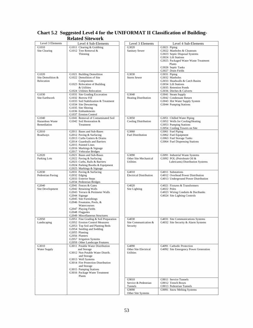
53
Chart 5.2 Suggested Level 4 for the UNIFORMAT II Classification of Building-Related Sitework
Level 3 Elements Level 4 Sub-Elements Level 3 Elements Level 4 Sub-ElementsG1010Site Clearing
G1011 Clearing & GrubbingG1012 Tree Removal & Thinning
G3020Sanitary Sewer
G3021 PipingG3022 Manholes & CleanoutsG3023 Septic Disposal SystemsG3024 Lift StationsG3025 Packaged Water Waste Treatment
PlantsG3026 Septic TanksG3027 Drain Fields
G1020Site Demolition &Relocation
G1021 Building DemolitionG1022 Demolition of Site ComponentsG1023 Relocation of Building & UtilitiesG1024 Utilities Relocation
G3030Storm Sewer
G3031 PipingG3032 ManholesG3033 Headwalls & Catch BasinsG3034 Lift StationsG3035 Retention PondsG3036 Ditches & Culverts
G1030Site Earthwork
G1031 Site Grading ExcavationG1032 Borrow FillG1033 Soil Stabilization & TreatmentG1034 Site DewateringG1035 Site ShoringG1036 EmbankmentsG1037 Erosion Control
G3040Heating Distribution
G3041 Steam SupplyG3042 Condensate ReturnG3043 Hot Water Supply SystemG3044 Pumping Stations
G1040Hazardous WasteRemediation
G1041 Removal of Contaminated SoilG1042 Soil Restoration & Treatment
G3050Cooling Distribution
G3051 Chilled Water PipingG3052 Wells for Cooling/HeatingG3053 Pumping StationsG3054 Cooling Towers on Site
G2010Roadways
G2011 Bases and Sub-BasesG2012 Paving & SurfacingG2013 Curbs Gutters & DrainsG2014 Guardrails and BarriersG2015 Painted LinesG2016 Markings & SignageG2017 Vehicular Bridges
G3060Fuel Distribution
G3061 Fuel PipingG3062 Fuel EquipmentG3063 Fuel Storage TanksG3064 Fuel Dispensing Stations
G2020Parking Lots
G2021 Bases and Sub-BasesG2022 Paving & SurfacingG2023 Curbs, Rails & BarriersG2024 Parking Booths & EquipmentG2025 Markings & Signage
G3090Other Site MechanicalUtilities
G3091 Industrial Waste SystemsG3092 POL (Petroleum Oil & Lubricants) Distribution Systems
G2030Pedestrian Paving
G2031 Paving & SurfacingG2032 EdgingG2033 Exterior StepsG2034 Pedestrian Bridges
G4010Electrical Distribution
G4011 SubstationsG4012 Overhead Power DistributionG4013 Underground Power Distribution
G2040Site Development
G2041 Fences & GatesG2042 Retaining WallsG2043 Terrace & Perimeter WallsG2044 SignageG2045 Site FurnishingsG2046 Fountains, Pools, & WatercoursesG2047 Playing FieldsG2048 FlagpolesG2049 Miscellaneous Structures
G4020Site Lighting
G4021 Fixtures & TransformersG4022 PolesG4023 Wiring Conduits & DuctbanksG4024 Site Lighting Controls
G2050Landscaping
G2051 Fine Grading & Soil PreparationG2052 Erosion Control MeasuresG2053 Top Soil and Planting BedsG2054 Seeding and SoddingG2055 PlantingG2056 PlantersG2057 Irrigation SystemsG2059 Other Landscape Features
G4030Site Communication &Security
G4031 Site Communications SystemsG4032 Site Security & Alarm Systems
G3010Water Supply
G3011 Potable Water Distribution and StorageG3012 Non Potable Water Distrib. and StorageG3013 Well SystemsG3014 Fire Protection Distribution and StorageG3015 Pumping StationsG3016 Package Water Treatment Plants
G4090Other Site ElectricalUtilities
G4091 Cathodic ProtectionG4092 Site Emergency Power Generation
G9010Service & PedestrianTunnels
G9011 Service TunnelsG9012 Trench BoxesG9013 Pedestrian Tunnels
G9090Other Site Systems
G9091 Snow Melting Systems
54
Improved Life-Cycle Costing—A Level-4 classification permits a more comprehensivelevel of building detail for assembling operation, maintenance, and repair costs inaddition to initial construction costs. Having lower level costs early in the design processhelps users select cost-effective sub-elements and whole building alternatives on a life-cycle cost basis.
Building Condition Assessment—Evaluating building conditions for Level-4 sub-elements as opposed to higher levels allows facility managers to track conditions at alevel that corresponds to typical operation, maintenance, and repair activities. Thisfacilitates reporting physical condition and estimating costs for correction, as well aspreparing long-term capital replacement budgets.
Library of Technical Data—By classifying and filing technical and product dataaccording to a Level-4 format, users will be able to find data more quickly.
Civil Works Sitework—The addition of 128 sub-elements in Level-4 sitework makesUNIFORMAT II feasible as a tool for organizing sitework on small and medium civilworks projects, such as parks.
Detailed Checklist—A formal Level-4 definition can be used as a checklist for mostUNIFORMAT II applications described in Sections 3 and 4. These includespecifications, estimates, technical design reviews, and building condition assessment. Agreater level of detail will enhance project control and improve cost effectiveness.

55
6. Summary and Suggestions for Further Work
6.1 Summary
The building community needs a building classification framework to provide aconsistent reference for the description, economic analysis, and management of buildingsduring all phases of their life cycle. This includes the planning, programming, design,construction, operations, and disposal phases. An elemental classification best satisfiesthis need because it facilitates economic analysis early in the design stage beforeadequate information has been developed to generate product-based estimates of projectcosts. Building elements are major components that are common to most buildings andthat perform a given function regardless of the design specification, construction method,or materials. Building foundations, exterior walls, and lighting are examples of elements.
UNIFORMAT II is an elemental classification that has been standardized by ASTM andis being widely adopted. It is proposed in this report as the appropriate classification foruse in every phase of the building process. Data entered in a consistent format will nothave to be reentered at subsequent phases of the building life cycle. Users willunderstand and be able to compare information at every phase because it is linked viacommon, uniform, physical elements or activities—the standard elements ofUNIFORMAT II. Better information, generated early in the construction process and atless cost, will help owners, builders, designers, facility managers, and occupants buildand manage their building for lower life-cycle costs.
Chapter 2 presents the 1997 ASTM UNIFORMAT II classification in three hierarchicallevels for both building elements and related sitework elements. The criteria for decidingin which part of the framework to locate each element is described in detail. Althoughthis 3-level hierarchy has been successfully implemented, some Level-3 elements aresufficiently general that it is not always clear where to classify more finely detailed items.For this reason we introduce a fourth hierarchical level (presented in detail in Chapter 5).Having a fourth-level category will improve communication, enhance project control, andincrease cost effectiveness in the building process.
Chapter 3 lists the many applications of UNIFORMAT II now in practice in all phases ofthe building life cycle. Selected applications in writing performance specifications,technical requirements, and preliminary project descriptions are described in detail. Anexample of a major benefit from using UNIFORMAT II in preliminary projectdescriptions at schematic design is that value engineering, life-cycle costing, and energyanalysis can be initiated before the design development stage is initiated. This allowsoptimization when there is potential for significant cost savings—i.e., before the projectdesign becomes locked in.
Chapter 4 treats elemental estimating, how it differs from product estimates, and theimportance of design cost analysis parameters. An elemental estimate formatincorporating cost analysis parameters is recommended to facilitate comparisons with

56
targeted costs and those of similar projects in historical databases. The elementalestimate format is illustrated with cost estimates generated for an eight-story officebuilding. Underlying estimate data sheets are also provided to help explain the derivationof the building’s summary elemental costs. To facilitate using UNIFORMAT II , sourcesof elemental cost and engineering data are provided.
Chapter 5 presents a recommended fourth level of sub-elements for UNIFORMAT II.The Level-4 sub-elements provide numerous advantages over the current three levels ofUNIFORMAT II. Improved cost data emerge, resulting in better cost estimates and animproved historical cost database. Most importantly, a Level-4 classification permitsmore comprehensive building details for assembling operation, maintenance, and repaircosts as well as initial construction costs. This helps users better estimate life-cycle costsand thereby make life-cycle, cost-effective building selections early in the design processwhen the potential for cost savings is greatest. Finally, having Level-4 sub-elementsallows facility managers to assess building conditions at a level that corresponds totypical operation, maintenance, and repair activities. This facilitates the reporting ofbuilding condition, the estimation of maintenance, repair, renovation, and retrofit costs,and the preparation of long-term capital replacement budgets.
6.2 Suggestions for Further Work
Five suggestions are proposed for further work. The first is to revise the ASTMUNIFORMAT II classification to incorporate the Level-4 sub-elements described inChapter 5. This will require collaboration among users of the classification and writersof the standard to arrive at a consensus of enhancements that will better helpUNIFORMAT II meet user needs. A Level-4 classification of sub-elements in building-related sitework with 128 designations would produce a framework that could beapplicable for small-to-medium-sized civil works projects such as parks, thus expandingsignificantly the user base for the standard.
The second suggestion is to develop counterpart formats to UNIFORMAT II for non-building applications. Figure 6.1 shows potential industry users of UNIFORMAT II.The shaded building and site-related boxes indicate that a standard format exists for thoseapplications. The dark-bordered box for bridges indicates that there is a “standard inprocess” on UNIFORMAT II for bridges. The other boxes represent potential areas forthe development of specialized UNIFORMAT II standard formats. Note that theanticipated benefits of a UNIFORMAT II for bridges or any of these other applicationsare similar to what we described in this report for buildings.
The third suggestion is to develop standard elemental units of measurement and costanalysis parameters or factors for use in comparing cost estimates among similar projectsand to a database of elemental costs. These units of measurement and cost analysisfactors would be candidates for ASTM standards.

57
Figure 6.1 Framework of the Built Environment
The fourth suggestion is to present to ASTM a standard summary format (based onTables 4.3, 4.4, and 4.5) for presenting elemental cost estimates of buildings duringdesign. Using the same UNIFORMAT II format consistently over time and over allprojects will ensure that managers and other audiences of economic presentations willunderstand exactly what elements contain and what they are projected to cost.UNIFORMAT II becomes the thread that ties project information together through allphases of the building’s life cycle.
The fifth suggestion is to use the UNIFORMAT II format to record information on theNational Construction Goals (NCGs). The NCGs were formulated by a broad crosssection of the construction industry to promote the competitiveness of the U.S.Construction industry. The program provides baseline measures of industry practices andtools and information on ways to reduce construction cycle time, first costs, life-cyclecosts, and injuries and illnesses. By providing a definitive and consistent format,UNIFORMAT II would promote performance improvement efforts through reference toinformation on industry norms (e.g., first costs for Levels 3 and 4) and the ability toidentify and benchmark against industry leaders.
SiteAcquisitions
Buildings(Chart 2.1)
RelatedSitework
(Chart 2.2)
Construction
Buildings Bridges Roads Dams Tunnels Railroads Other
BuiltEnvironment

58

59
APPENDIX A Author Profiles
ROBERT P. CHARETTE
Mr. Charette, a professional engineer, is an associate adjunct professor at ConcordiaUniversity. He led the ASTM Building Economics Subcommittee in developing ASTM'sUNIFORMAT II Standard Classification for Building Elements and Related Sitework.He is accredited as a Certified Value Specialist by the Society of American ValueEngineers and qualified as a Professional Quantity Surveyor with the Canadian Instituteof Quantity Surveyors. He was formerly National Director of the Value Engineering andLife-Cycle Costing Services for Hanscomb Consultants in Canada and the United States.Mr. Charette is a member of the Architectural Engineering Institute of the AmericanSociety of Civil Engineers, the Construction Specification Institute, the Design-BuildInstitute of America, and the Association for Project Managers. He has lectured andpresented seminars on Value Engineering, Life-Cycle Costing, and UNIFORMAT II forDesign Management at both the undergraduate and post graduate levels at McGillUniversity's School of Architecture, Design and Modelling Centre; Schools ofArchitecture and Engineering at the University of Montreal; Ecole de TechnolgieSuperieure; Concordia University; Harvard Graduate School of Design; and theUniversity of Wisconsin.
HAROLD E. MARSHALL
Dr. Marshall heads the Office of Applied Economics at the National Institute ofStandards and Technology. His specialty is developing standard economic methods andrisk analysis techniques for evaluating investment projects. Dr. Marshall is co-author ofa book on building economics, and has published over 40 articles, chapters in books, andtechnical papers. He chairs for the American Society for Testing and Materials theBuilding Economics Subcommittee which has produced thirteen standard economicmethods used worldwide for evaluating investments in buildings and construction. Asadvisory editor to the international journal Construction Management and Economics andto AACE International's Cost Engineering, he keeps abreast of developments at home andabroad in building economics. A graduate of the George Washington University (Ph.D.in 1969, M.A., 1965, and B.A., 1964), Dr. Marshall's early career included teachingeconomics for the George Washington University, George Mason University, and for twoyears on World Campus Afloat's around-the-world shipboard college. In recognition ofhis contributions in building economics, Dr. Marshall received in 1986 the AmericanAssociation of Cost Engineers' highest honor, the Award of Merit, and in 1988 theAmerican Society for Testing and Materials Award of Merit and accompanying honorarytitle of Fellow of the Society.

60


63
• floor slabs & decks• inclined & stepped floors• expansion & contraction joints• balcony construction• suspended ramps• exterior stairs and fire escapes• other floor construction (e.g., catwalks,
space frames, etc.)
• applied & suspended ceiling & floorfinishes (see section C 3020, FloorFinishes & section C 3030, CeilingFinishes)
• stair construction (see section C 2010,Stair Construction)
• balcony walls & railings (see sectionB 2010, Exterior Walls)
B 1020 Roof Construction
Includes
• roof structural frame• structural interior walls supporting roof• roof decks, slabs & sheathing• canopies• other roof construction
Excludes
• roof coverings (see section B 3010, RoofCoverings)
• skylights & roof openings (see sectionB 3020 Openings)
• stair construction (see section C 2010,Stair Construction)
B 20 Enclosure
B 2010 Exterior Walls
Includes
• exterior wall construction with facingmaterials, exterior applied finishes,
• back-up construction, framing, wallboard,parapets, insulation & vapor retarders,sheathing, wallboard
• exterior load-bearing wall construction• exterior louvers & screens• exterior sun control devices• balcony walls & railings• exterior soffits
Excludes
• applied finishes to interior faces ofexterior walls (see section C 3010, WallFinishes)
• columns and beams in exterior walls (seesection B 10, Superstructure)
• venetian blinds (see section E 20,Furnishings)
• other interior sun control devices (seesection E 20, Furnishings)
• roof eaves and eaves soffits (see sectionB 3010, Roof Coverings)
• glazed curtain walls (see section B 2020,Windows)

64
B 2020 Exterior Windows
Includes
• windows• storefronts• curtain walls• exterior painting of windows• wall opening elements such as lintels,
sills, flashings, etc.
Excludes
• window treatments (see section E 20,Furnishings)
B 2030 Exterior Doors
Includes
• personnel doors• revolving doors• overhead doors• other doors (e.g., hanger doors, blast-
resistant doors, etc.)
B 30 Roofing
B 3010 Roof Coverings
Includes
• roofing membranes• traffic coatings• waterproof membranes below paving• expansion joints• vapor retarder1
• roof & deck insulation• roof fill• flashings & trim• gutters & downspouts• eaves & eaves soffits
Excludes
• roof openings (see section B 3020, RoofOpenings)
• roof drains (see section D 2040, RainWater Drainage)
• parapets (see section B 2010, ExteriorWalls)
1 A vapor retarder was formerly referred to as a vapor barrier.

70
D 3020 Heat Generating Systems
Includes
• boilers, including electric• piping and fittings adjacent to boilers• primary pumps• auxiliary equipment• equipment & piping insulation
Excludes
• electric space unit heaters & baseboard,fuel fired unit heaters, furnaces (seesection D 3050, Terminal & PackageUnits)
controls & instrumentation (see section D3060, Controls & Instrumentation)
D 3030 Cooling Generating Systems
Includes
• chillers• cooling towers & evaporative coolers• condensing units• piping & fittings• primary pumps• direct expansion systems• equipment & piping insulation
Excludes
• secondary chilled water pumps (seesection D 3040, Distribution Systems)
• distribution piping (see section D 3040,Distribution Systems)
• controls & instrumentation (see section D3060, Controls & Instrumentation)
D 3040 Distribution Systems
Includes
• supply & return air systems, including airhandling units with coils (electricincluded), filters, ductwork, & associateddevices such as VAV boxes, duct heaters,induction units & grilles
• ventilation & exhaust systems• steam, hot water, glycol & chilled water
distribution• associated terminal devices including
convectors, fan-coil units, & inductionunits, but not water & steam unit heaters
• heat recovery equipment• auxiliary equipment such as secondary
pumps, heat exchangers, soundattenuation, & vibration isolation
• piping, duct, & equipment insulation
Excludes
• electric, gas, or oil fired unit heaters (seesection D 3050, Terminal & PackageUnits)
• furnaces (gas or oil) (see section D 3050,Terminal & Package Units)
• floor, ceiling, & rooftop package units(see section D 3050, Terminal & PackageUnits)
• controls & instrumentation (see section D3060, Controls & Instrumentation)

71
D 3050 Terminal and Package Units
Includes
• electric baseboard• electric or fossil fuel fired unit heaters,
unit ventilators, & radiant heaters• window or through-the-wall air
conditioners, with or without heating ofany type
• reverse-cycle, water- or air-cooled,terminal heat pumps
• wall sleeves where required• electric or fossil fuel fired air-handling
units or furnaces• self-contained, air- or water-cooled, floor,
ceiling, & rooftop air conditioners, & heatpumps
• ductwork and accessories, including fluestacks
• factory-integrated controls
Excludes
• piping & accessories (see section D 3040,Distribution Systems)
• hydronic or steam convectors, fan-coilunits (see section D 3040, DistributionSystems)
• cooling towers, remote air-cooledcondensers, evaporative coolers (seesection D 3030, Cooling GenerationSystems)
• air-handling units with only hydronicheating or steam coils (see section D3040, Distribution Systems)
• air-handling units with chilled water ordirect expansion cooling coils (see sectionD 3040, Distribution Systems)
D 3060 Controls and Instrumentation
Includes
• heating generating systems• cooling generating systems• heating/cooling air handling units• exhaust & ventilating systems• terminal devices• energy monitoring & control• building automation systems
Excludes
• factory-installed controls, when anintegral part of terminal & package units(see section D 3050, Terminal & PackageUnits)
D 3070 Systems Testing and Balancing
Includes
• piping systems testing & balancing• air systems testing & balancing

72
D3090 Other HVAC Systems and EquipmentIncludes
• special cooling systems and devices• special humidity control• dust and fume collectors• air curtains• air purifiers• paint spray booth ventilation systems• general construction items associated with
mechanical systems
D 40 Fire Protection
D 4010 Sprinklers
Includes
• water supply equipment• piping valves & fittings• sprinkler heads & release devices
D 4020 Standpipes
Includes
• water supply equipment• piping valves & fittings• cabinets & hoses
D 4030 Fire Protection Specialties
Includes
• fire extinguishers• fire extinguisher cabinets

73
D 4090 Other Fire Protection Systems
Includes
• carbon dioxide systems• clean agent systems• foam generating systems• dry chemical systems• exhaust hood systems
D 50 Electrical
D 5010 Electrical Service and Distribution
Includes
• primary transformers• secondary transformers• main switchboard• interior distribution transformers• branch circuit panels• enclosed circuit breakers• motor control centers• conduit and wiring to circuit panels
Excludes
• outdoor transformers (see section G 4010,Electrical Distribution)
• emergency power (see section D 5090,Other Electrical Systems)
• branch wiring (see section D 5020,Lighting & Branch Wiring)
D 5020 Lighting and Branch Wiring
Includes
• branch wiring & devices for lightingfixtures
• lighting fixtures• branch wiring for devices & equipment
connections• devices• exterior building lighting
Excludes
• underfloor raceways (see section D 5090,Other Electrical Systems)
• exterior site lighting (see section G 4020,Site Lighting)
D 5030 Communications and Security
Includes
• fire alarm systems
Excludes
• other electrical systems (see section D5090, Other Electrical Systems)

74
• call systems• telephone systems• local area networks• public address & music systems• intercommunication systems & paging• clock & program systems• television systems• security systems
D 5090 Other Electrical Systems
Includes
• emergency generators• UPS• emergency lighting systems• power factor correction• lightning & grounding protection systems• raceway systems
• power generation systems
Excludes
• electric baseboard (see section D 3050,Terminal & Package Units)
• electric coils & duct heaters (see sectionD 3040, Distribution Systems)
• building automation & energy monitoringsystems (see section D 3060, Controls &Instrumentation)
• communications & security systems (seesection D 5030, Communications &Security)
E 10 Equipment
E 1010 Commercial EquipmentIncludes
• security and vault equipment• teller and service equipment• registration equipment• checkroom equipment• mercantile equipment• commercial laundry and dry cleaning
equipment• vending equipment• office equipment

75
E 1020 Institutional Equipment
Includes
• ecclesiastical equipment• library equipment• theater and stage equipment• instrumental equipment• audio-visual equipment• detention equipment• laboratory equipment• medical equipment• mortuary equipment
E 1030 Vehicular EquipmentIncludes
• vehicular service equipment• parking control equipment• loading dock equipment
E 1090 Other EquipmentIncludes
• maintenance equipment• solid waste handling equipment• food service equipment• residential equipment• unit kitchens• darkroom equipment• athletic, recreational, and therapeutic
equipment• planetarium equipment• observatory equipment• agricultural equipment

76
E 20 Furnishings
E 2010 Fixed Furnishings
Includes
• fixed artwork• fixed casework• window treatment• fixed floor grilles and mats• fixed multiple seating• fixed interior landscaping
E 2020 Movable FurnishingsIncludes
• movable artwork• furniture and accessories• movable rugs and mats• movable multiple seating• movable interior landscaping
F 10 Special Construction
F 1010 Special Structures
Includes
• air-supported structures• pre-engineered structures• other special structures
Excludes
• solar & wind energy supply (see sectionD 3010, Energy Supply)
F 1020 Integrated Construction
Includes
• integrated assemblies• special purpose rooms• other integrated construction

77
F 1030 Special Construction Systems
Includes
• sound, vibration, and seismic construction• radiation protection• special security systems• other special construction systems
F 1040 Special facilities
Includes
• aquatic facilities• ice rinks• site constructed incinerators• kennels and animal shelters• liquid and gas storage tanks• other special facilities
F 1050 Special Controls and InstrumentationIncludes
• recording instrumentation• building automation systems• other special controls and instrumentation
F 20 Selective Building Demolition
F 2010 Building Elements Demolition
Includes
• demolition of existing buildingcomponents
Excludes
• site demolition (see section G 1020, SiteDemolition & Relocations)
F 2020 Hazardous Components Abatement
Includes
• removal or encapsulation of hazardousbuilding materials & components

78
B.2 Description of Building-Related Sitework
The following lists show what items are included and excluded in the siteworkclassification at Level 3. Note again that the numbers are for the purpose of organizing thereport and are not classification numbers for the elements.
G 10 Site Preparation
G 1010 Site Clearing
Includes
• clearing & grubbing• tree removal & thinning
G 1020 Site Demolition and Relocations
Includes
• complete building demolition• demolition of site components• relocation of buildings & utilities
Excludes
• selective demolition within building (seesection F 20, Selective BuildingDemolition)
G 1030 Site Earthwork
Includes
• grading, excavating & fill to modify sitecontours
• soil stabilization & treatment• site watering• site shoring• embankments
Excludes
• building excavation for foundations andbasements (see section A 10, Foundations& section A 20, Basement Construction)
G 1040 Hazardous Waste Remediation
Includes
• removal & restoration of contaminatedsoil

79
G 20 Site Improvement
G 2010 Roadways
Includes
• paving sub-base• paving & surfacing• curbs & gutters• rails & barriers• painted lines• markings & signage
G 2020 Parking Lots
Includes
parking lot paving & surfacing• curbs, rails & barriers• parking booths & equipment• markings & signage
G 2030 Pedestrian Paving
Includes• paving & surfacing• exterior steps
Excludes• waterproof membranes under terrace &
plaza paving (see section G 3010, RoofCoverings)
G 2040 Site Development
Includes• fences & gates• retaining walls• terrace & perimeter walls• signs• site furnishings• fountains, pools, & watercourses• playing fields• flagpoles• miscellaneous structures
• site equipment (for example car wash,banking system and theatre equipmentlocated on the site)
Excludes
• signs (see section G 2010, Roadways §ion G 2020, Parking Lots)

80
G 2050 Landscaping
Includes
• fine grading & soil preparation• top soil & planting beds• seeding & sodding• planting• planters• other landscape features• irrigation systems
Excludes
• interior planters & planting (see sectionE 20, Furnishings)
• site grading (see section G 1030, SiteEarthwork)
G 30 Site Mechanical Utilities G 3010 Water Supply
Includes
• potable & non-potable water systems• well systems• fire protection systems• pumping stations• water storage
Excludes
• irrigation systems (see section G 2050,Landscaping)
G 3020 Sanitary Sewer
Includes
• piping• manholes• septic tanks• lift stations• package waste water treatment plants

81
G 3030 Storm Sewer
Includes
• piping• manholes• catch basins• lift stations• retention ponds
• ditches & culverts
G 3040 Heating Distribution
Includes
• steam supply• condensate return• hot water supply systems
Excludes
• Service tunnels (see section G 9090,Service and Pedestrian Tunnels)
G 3050 Cooling Distribution
Includes
• chilled water piping• wells for cooling• pumping stations
• cooling towers on site
Excludes
• service tunnels (see section G 9090,Service and Pedestrian Tunnels)
G 3060 Fuel Distribution
Includes• piping• equipment
• storage tanks
G3090 Other Site MechanicalUtilities
Includes
• industrial waste systems• POL (Petroleum Oil & Lubricants)
distribution systems

82
G 40 Site Electrical Utilities
G 4010 Electrical Distribution
Includes
• substations• overhead power distribution• underground power distribution• ductbanks
• grounding
G 4020 Site Lighting
Includes
• fixtures & transformers• poles• wiring conduits & ductbanks• controls• grounding
G 4030 Site Communications and Security
Includes
• overhead & underground communications• site security & alarm systems• ductbanks
• grounding
G 4040 Other Site Electrical Utilities
Includes
• cathodic protection• emergency power generation

83
G 90 Other Site Construction
G 9010 Service and Pedestrian Tunnels
Includes
• constructed service and pedestriantunnels
• prefabricated service tunnels & trenchboxes
G 9090 Other Site Systems
Includes
• snow melting systems

84

89
APPENDIX E References
Ahuja, N. Hira, and Campbell, Walter J. Estimating from Concept to Completion(Englewood Cliffs, NJ: Prentice-Hall, Inc., 1988).
American Institute of Architects. “Chapter B5—Design and Construction CostManagement,” Architect’s Handbook of Professional Practice (Washington, DC:American Institute of Architects, 1984).
American Institute of Architects. MASTERCOST Instruction Manual (Washington, DC:American Institute of Architects, 1974).
American Institute of Architects. AIA Document D101— The Architectural Area andVolume of Buildings (Washington, DC: The American Institute of Architects, 1980).
American Institute of Architects. The Architect’s Handbook of Professional Practice —7th Edition (Washington, DC: American Institute of Architects, 1992).
American Society for Testing and Materials. ASTM E 1496-98, “Standard Practice forMeasuring Cost Risk of Buildings and Building Systems" (West Conshohocken, PA:American Society for Testing and Materials, 1998).
American Society for Testing and Materials. ASTM E 1557-97, "Standard Classificationfor Building Elements and Related Sitework- UNIFORMAT II" (West Conshohocken,PA: American Society for Testing and Materials, 1997).
Bowen, Brian and Robert P. Charette. "Elemental Cost Classification Standard forBuilding Design," 1991 American Association of Cost Engineers (AACE)Transactions (Seattle, WA: American Association of Cost Engineers, 1991).
Bowen, Brian, Robert Charette, and Harold Marshall. UNIFORMAT II – ARecommended Classification for Building Elements and Related Sitework, SpecialPublication 841 (Gaithersburg, MD: National Institute of Standards and Technology,1992).
Canadian Institute of Quantity Surveyors. Elemental Cost Analysis-Method ofMeasurement and Pricing (Toronto, Ontario, Canada: Canadian Institute of QuantitySurveyors, first issued 1972, revised 1990).
Charette, Robert P. "New Design Management Tools for Projects Managers," TheAssociation for Project Managers (APM) Journal, Volume 5, Issue 3, May 1998.Available on the APM website, www.construction.st/ UNIFORMAT.htm.

90
Construction Specifications Institute. Practice FF/180. “Preliminary Project Descriptionand Outline Specifications,” Manual of Practice (Alexandria, VA: The ConstructionSpecifications Institute, 1996).
Construction Specifications Institute. MasterFormat 95™ (Alexandria, VA: TheConstruction Specifications Institute, 1995 edition).
Construction Specifications Institute. UniFormatTM: A Uniform Classification ofConstruction Systems and Assemblies (Alexandria, VA: The ConstructionSpecifications Institute, 1998 Edition).
Construction Specifications Institute and Design Build Institute of America.PerSpectiveTM, The Performance System for Project Teams (Alexandria, VA:Construction Specifications Institute; Washington, DC: Design-Build Institute ofAmerica, 1993). Web site—www.perspective.net.com.
Cox, B.J. and Horsley, William. Square Foot Estimating Methods, 2nd Edition(Kingston, MA: R.S. Means Co., Inc., 1995).
Dell’Isola, A.J and Kirk, S.J. Life Cycle Costing for Design Professionals, 2nd Edition,(New York, NY: McGraw-Hill, Inc., 1995).
Dell’Isola, Michael. “Value Engineering Applications Using UNIFORMAT II,”Proceedings of the Society of American Value Engineers (Atlanta, GA, 1998, pp. 72-82.)
Delta Research Corporation. TRACES Generic Work Breakdown Structure,(Washington, DC: Tri Services WBS Subcommittee, 1992).
General Services Administration, Handbook PBS P 3440.5, Project EstimatingRequirements (Washington, DC: General Services Administration, August 24, 1981).
Hanscomb Associates, Inc. Automated Cost Control & Estimating System (Washington,DC: General Services Administration, 1975.)
International Organization for Standardization, ISO 9001, "Standard Model for QualityAssurance in Design, Development, Production, Installation, and Servicing," Element4.9—Process Control (Geneva, Switzerland: International Organization forStandardization).
Killingsworth, Roger. Cost Control in Building Design (Kingston, MA: R.S. Means Co.Inc., 1988).

91
Marshall, Harold E. and Ruegg, Rosalie T. Recommended Practice for MeasuringBenefit/Cost and Savings-to-Investment Ratios for Buildings and Building Systems,Interagency Report 81-2397 (Gaithersburg, MD: National Institute of Standards andTechnology, November 1981).
Marshall, Harold E. Recommended Practice for Measuring Net Benefits and InternalRates of Return for Investments in Buildings and Building Systems, InteragencyReport 83-2657 (Gaithersburg, MD: National Institute of Standards and Technology,October 1983).
Marshall, Harold E. Recommended Practice for Measuring Simple and DiscountedPayback for Investments in Building and Building Systems, Interagency Report 84-2850 (Gaithersburg, MD: National Institute of Standards and Technology, March1984).
Marshall, Harold E. Techniques for Treating Uncertainty and Risk in the EconomicEvaluation of Building Investments, Special Publication 757 (Gaithersburg,MD:National Institute of Standards and Technology, September 1988).
Martin, J. and Rumble, P. An Elemental Approach to Design and Build Contracts(Berkshire, England: The Chartered Institute of Buildings, Construction Papers No.79, 1997).
McGraw Hill. Time Saver Standards for Architectural Design, 7th Edition (McGraw Hill,1997).
National Institute of Building Sciences. Construction Criteria Database (Washington,DC: National Institute of Building Sciences).
Nisbet, James. Called to Account—Quantity Surveying 1936-1986 (London, England:Stokes Publications, 1989).
Parker, Donald E. and Dell’Isola, Alphonse J. Project Budgeting for Buildings (NewYork, NY: Van Nostrand Reinhold, 1991).
The Royal Architectural Institute of Canada. "Cost Planning and Cost ControlTechniques," Volume 3, Canadian Handbook of Practice for Architects, 1st Edition(Ottawa, Ontario, Canada: The Royal Architectural Institute of Canada, 1978).
Royal Institution of Chartered Surveyors (RICS) — Building Cost Information ServiceLtd. (BCIS). Elements for Design and Build (London, England: The RoyalInstitution of Chartered Surveyors, 1996).
Royal Institution of Chartered Surveyors. Standard Form of Cost Analysis (London,England: The Building Cost Information Service, 1969 (Reprinted December 1987)).

92
R.S. Means Co., Inc. Hanscomb's 1999 Yardsticks for Costing (Kingston, MA: R.S.Means Co., Inc., 1999).
R.S. Means Co., Inc. Means Assemblies Cost Data, 24th Annual Edition (Kingston, MA:R.S. Means Co., Inc., 1999).
R.S. Means Co., Inc. Means Building Construction Cost Data, 57th Annual Edition(Kingston, MA: R.S. Means Co., Inc., 1999).
R.S. Means Co., Inc. Means Electrical Cost Data, 22nd Annual Edition (Kingston, MA:R.S. Means Co., Inc., 1999)
R.S. Means Co., Inc. Means Graphic Construction Standards (Kingston, MA: R.S.Means Co., Inc., 1986).
R.S. Means Co., Inc. Means Interior Cost Data, 16th Annual Edition (Kingston, MA:R.S. Means Co., Inc., 1999).
R.S. Means Co., Inc. Means Mechanical Cost Data, 22nd Annual Edition (Kingston, MA:R.S. Means Co., Inc., 1999).
R.S. Means Co., Inc. Means Plumbing Cost Data, 22nd Annual Edition (Kingston, MA:R.S. Means Co., Inc., 1999).
R.S. Means Co., Inc. Means Residential Cost Data, 18th Annual Edition (Kingston, MA:R.S. Means Co., Inc., 1999).
R.S. Means Co., Inc. Means Sitework and Landscape Cost Data, 18th Annual Edition(Kingston, MA: R.S. Means Co., Inc., 1999).
R.S. Means Co., Inc. Means Square Foot Costs, 20th Annual Edition (Kingston, MA:R.S. Means Co., Inc., 1999).
Ruegg, Rosalie T., Peterson, Stephen R., and Marshall, Harold E. Recommended Practicefor Measuring Life-Cycle Costs of Buildings and Building Systems, InteragencyReport 80-2040 (Gaithersburg, MD: National Institute of Standards and Technology,June 1980).
Whitestone Research. The Whitestone Building Maintenance and Repair Cost Reference1999 (Santa Barbara, CA: Whitestone Research Corporation, 1999).

93
UNIFORMAT II Classification of Building-Related Sitework (E1557-97)
Level 1Major Group Elements
Level 2Group Elements
Level 3Individual Elements
G10 Site Preparation G1010 Site ClearingG1020 Site Demolition and RelocationsG1030 Site EarthworkG1040 Hazardous Waste Remediation
G20 Site Improvements G2010 RoadwaysG2020 Parking LotsG2030 Pedestrian PavingG2040 Site DevelopmentG2050 Landscaping
G30 Site Mechanical Utilities G3010 Water SupplyG3020 Sanitary SewerG3030 Storm SewerG3040 Heating DistributionG3050 Cooling DistributionG3060 Fuel DistributionG3090 Other Site Mechanical Utilities
G40 Site Electrical Utilities G4010 Electrical DistributionG4020 Site LightingG4030 Site Communications & SecurityG4090 Other Site Electrical Utilities
G BUILDING SITEWORK
G90 Other Site Construction G9010 Service and Pedestrian TunnelsG9090 Other Site Systems & Equipment