Embed Size (px)
Citation preview
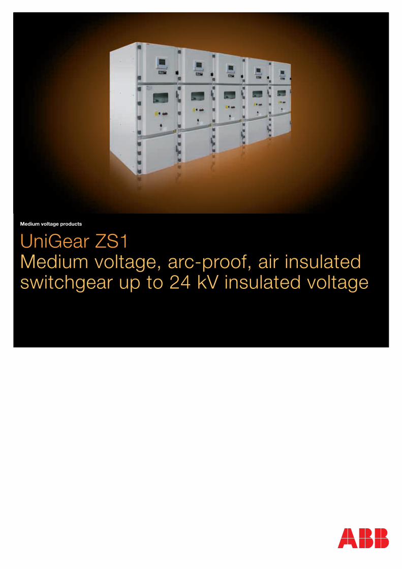
Medium voltage products
UniGear ZS1 Medium voltage, arc-proof, air insulated switchgear up to 24 kV insulated voltage

3
Index
1. UniGear ZS1 4 Description 8 IEC Classification 10 Design features 12 Fully type-tested 14 Safety 18 Vacuum circuit-breaker 22 VD4G – Vacuum circuit-breaker for generator switching applications 24 Gas circuit-breaker 26 Vacuum contactor 28 Switch-disconnector 30 Service trucks 32 Ultra fast earthing switch 34 Is-limiter fault-current limitation 36 Instrument transformers 38 Current and voltage sensors 42 Cable terminations 44 Distribution automation 70 Automatic transfer system 72 UniGear ZS1 Digital 74 Typical units 76 Technical data
2. UniGear ZS1 - Double Busbar System 80 Description 82 Characteristics 84 Typical units 86 Technical data
3. Marine Applications 90 Description 92 Characteristics 94 Typical units 96 Technical data
UniGear ZS1 - Double Level 98 Description 100 Characteristics 102 Typical units 104 Technical data
4
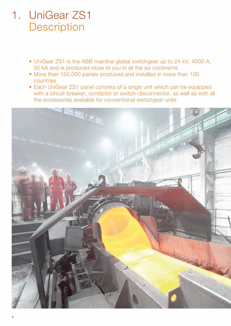
• UniGear ZS1 is the ABB mainline global switchgear up to 24 kV, 4000 A, 50 kA and is produced close to you in all the six continents
• More than 150,000 panels produced and installed in more than 100 countries
• Each UniGear ZS1 panel consists of a single unit which can be equipped with a circuit-breaker, contactor or switch-disconnector, as well as with all the accessories available for conventional switchgear units
1. UniGear ZS1 Description
5
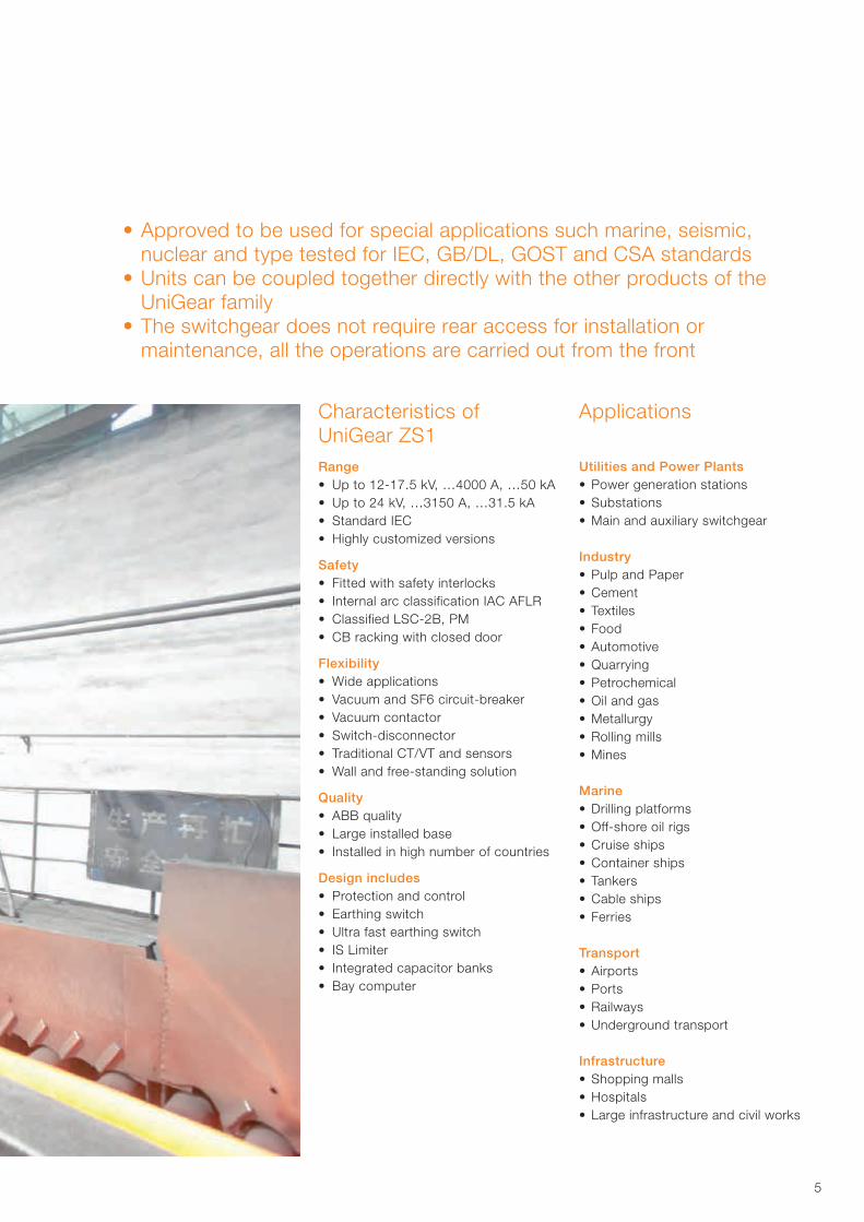
Range• Up to 12-17.5 kV, …4000 A, …50 kA• Up to 24 kV, …3150 A, …31.5 kA• Standard IEC• Highly customized versions
Safety• Fitted with safety interlocks• Internal arc classification IAC AFLR• Classified LSC-2B, PM• CB racking with closed door
Flexibility• Wide applications• Vacuum and SF6 circuit-breaker• Vacuum contactor• Switch-disconnector• Traditional CT/VT and sensors• Wall and free-standing solution
Quality• ABB quality• Large installed base• Installed in high number of countries
Design includes• Protection and control• Earthing switch• Ultra fast earthing switch• IS Limiter• Integrated capacitor banks• Bay computer
Utilities and Power Plants• Power generation stations• Substations• Main and auxiliary switchgear
Industry• Pulp and Paper• Cement• Textiles• Food• Automotive• Quarrying• Petrochemical• Oil and gas• Metallurgy• Rolling mills• Mines
Marine• Drilling platforms• Off-shore oil rigs• Cruise ships• Container ships• Tankers• Cable ships• Ferries
Transport• Airports• Ports• Railways• Underground transport
Infrastructure• Shopping malls• Hospitals• Large infrastructure and civil works
Characteristics of UniGear ZS1
Applications
• Approved to be used for special applications such marine, seismic, nuclear and type tested for IEC, GB/DL, GOST and CSA standards
• Units can be coupled together directly with the other products of the UniGear family
• The switchgear does not require rear access for installation or maintenance, all the operations are carried out from the front
6
1. UniGear ZS1 Description
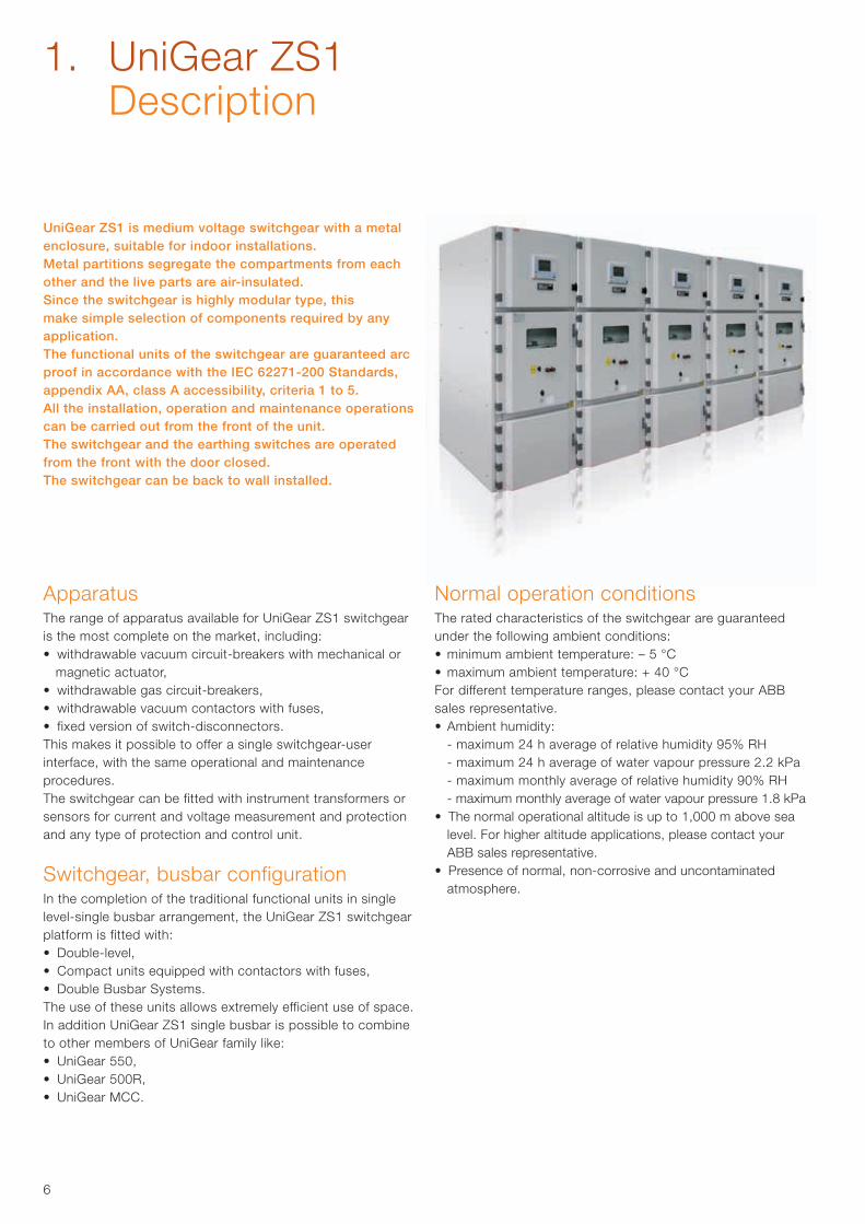
UniGear ZS1 is medium voltage switchgear with a metal enclosure, suitable for indoor installations.Metal partitions segregate the compartments from each other and the live parts are air-insulated.Since the switchgear is highly modular type, this make simple selection of components required by any application.The functional units of the switchgear are guaranteed arc proof in accordance with the IEC 62271-200 Standards, appendix AA, class A accessibility, criteria 1 to 5.All the installation, operation and maintenance operations can be carried out from the front of the unit.The switchgear and the earthing switches are operated from the front with the door closed.The switchgear can be back to wall installed.
ApparatusThe range of apparatus available for UniGear ZS1 switchgear is the most complete on the market, including:• withdrawable vacuum circuit-breakers with mechanical or
magnetic actuator,• withdrawable gas circuit-breakers,• withdrawable vacuum contactors with fuses,• fixed version of switch-disconnectors.This makes it possible to offer a single switchgear-user interface, with the same operational and maintenance procedures.The switchgear can be fitted with instrument transformers or sensors for current and voltage measurement and protection and any type of protection and control unit.
Switchgear, busbar configurationIn the completion of the traditional functional units in single level-single busbar arrangement, the UniGear ZS1 switchgear platform is fitted with:• Double-level,• Compact units equipped with contactors with fuses,• Double Busbar Systems. The use of these units allows extremely efficient use of space. In addition UniGear ZS1 single busbar is possible to combine to other members of UniGear family like:• UniGear 550,• UniGear 500R,• UniGear MCC.
Normal operation conditionsThe rated characteristics of the switchgear are guaranteed under the following ambient conditions:• minimum ambient temperature: – 5 °C• maximum ambient temperature: + 40 °CFor different temperature ranges, please contact your ABB sales representative.• Ambient humidity: - maximum 24 h average of relative humidity 95% RH - maximum 24 h average of water vapour pressure 2.2 kPa - maximum monthly average of relative humidity 90% RH - maximum monthly average of water vapour pressure 1.8 kPa• The normal operational altitude is up to 1,000 m above sea
level. For higher altitude applications, please contact your ABB sales representative.
• Presence of normal, non-corrosive and uncontaminated atmosphere.
7
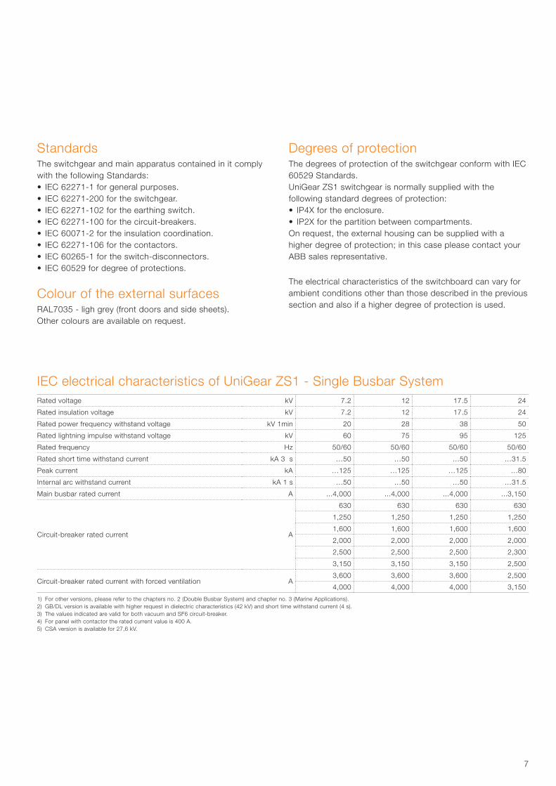
IEC electrical characteristics of UniGear ZS1 - Single Busbar SystemRated voltage kV 7.2 12 17.5 24
Rated insulation voltage kV 7.2 12 17.5 24
Rated power frequency withstand voltage kV 1min 20 28 38 50
Rated lightning impulse withstand voltage kV 60 75 95 125
Rated frequency Hz 50/60 50/60 50/60 50/60
Rated short time withstand current kA 3 s …50 …50 …50 …31.5
Peak current kA …125 …125 …125 …80
Internal arc withstand current kA 1 s …50 …50 …50 …31.5
Main busbar rated current A ...4,000 ...4,000 ...4,000 ...3,150
Circuit-breaker rated current A
630 630 630 630
1,250 1,250 1,250 1,250
1,600 1,600 1,600 1,600
2,000 2,000 2,000 2,000
2,500 2,500 2,500 2,300
3,150 3,150 3,150 2,500
Circuit-breaker rated current with forced ventilation A3,600 3,600 3,600 2,500
4,000 4,000 4,000 3,150
1) For other versions, please refer to the chapters no. 2 (Double Busbar System) and chapter no. 3 (Marine Applications).2) GB/DL version is available with higher request in dielectric characteristics (42 kV) and short time withstand current (4 s).3) The values indicated are valid for both vacuum and SF6 circuit-breaker.4) For panel with contactor the rated current value is 400 A.5) CSA version is available for 27,6 kV.
StandardsThe switchgear and main apparatus contained in it complywith the following Standards:• IEC 62271-1 for general purposes.• IEC 62271-200 for the switchgear.• IEC 62271-102 for the earthing switch.• IEC 62271-100 for the circuit-breakers.• IEC 60071-2 for the insulation coordination.• IEC 62271-106 for the contactors.• IEC 60265-1 for the switch-disconnectors.• IEC 60529 for degree of protections.
Colour of the external surfacesRAL7035 - ligh grey (front doors and side sheets).Other colours are available on request.
Degrees of protectionThe degrees of protection of the switchgear conform with IEC 60529 Standards.UniGear ZS1 switchgear is normally supplied with the following standard degrees of protection:• IP4X for the enclosure.• IP2X for the partition between compartments.On request, the external housing can be supplied with a higher degree of protection; in this case please contact your ABB sales representative.
The electrical characteristics of the switchboard can vary for ambient conditions other than those described in the previous section and also if a higher degree of protection is used.
8
With the release of the IEC 62271-200 standard, new definitions and classifications of Medium Voltage switchgear have been introduced.One of the most significant changes is that classification of switchgear into metal-enclosed, compartmented and cubicle types has been abandoned.The revision of switchgear classification rules has been based on the user’s point of view, in particular on aspects like service and maintenance of the switchgear, according to the requirements and expectations for proper management, from installation to dismantling.In this context, Loss of Service Continuity (LSC) has been selected as a fundamental parameter for the user.According to the IEC 62271-200, UniGear ZS1 switchgear can be defined as follows.
Loss of service continuity - LSC-2BThe various LSC categories describe the possibility of keeping other compartments and/or panels energized while a compartment in the main circuit is opened. The defined categories are:• LSC-1: The whole switchgear shall be put out of service for
opening a main circuit compartment for normal operation and/ornormal maintenance or for gaining access to any switchgear components.
• LSC-2A: The same as LSC-1 with the exception that the main busbars and the functional units adjacent to the one under maintenance can remain energized.
• LSC-2B: The same as LSC-2A with the exception that the cable compartment can remain energized.
UniGear ZS1 is classified as LSC-2B because the busbar, circuit-breaker and cable compartments are physically and electrically segregated.This is the category that defines the possibility of accessing the circuit-breaker compartment with the busbars and cables energized. In case of using the fixed version of the switch-disconnector, the panel is defined LSC-2A because the cable and apparatus compartments are not phisically segregated.
Partition Metallic - PMWith regard to the type of partitions or shutters between live parts and an open compartment, a distinction is made between two partition classes:• Class PM (Partition made of Metal);• Class PI (Partition made of Insulating material).UniGear ZS1 is defined with PM partition class having the segregation between compartments made of metallic sheets/shutters.
Interlock-controlled accessible compartmentThe front side of UniGear ZS1 is classified interlock-controlled because the access of the compartments containing high-voltage parts, intended to be opened for normal operation and/or normal maintenance, is controlled by the integral design of the switchgear.
Tool-based accessible compartmentThe rear part of the UniGear ZS1 is classified tool-based because it is possible to open the compartment containing high-voltage parts, that may be opened, but not for normal operation and maintenance, only using a tool. Special procedures are required.
Internal arc classification – IAC AFLRUniGear ZS1 switchgear is classified IAC AFLR.When the switchgear is specified and installed, some fundamental points must be taken into consideration:• Level of the fault current (16...50 kA).• Duration of the fault (0.1...1s).• Escape routes for the hot and toxic gases produced by
combustion of materials.• Dimensions of the room, with special attention to the height.Please consult your ABB representatives for detailedinformation.
1. UniGear ZS1 IEC Classification
9

10
CompartmentsEach switchgear unit consists of three power compartments: circuit-breaker [A], busbars [B] and cables [C]; please refer to figure.Each unit is fitted with a low voltage compartment [D], where all the auxiliary instruments are housed.Arc-proof switchgear is normally provided with a duct [E] for evacuation of the gases produced by an arc; different types of gas ducts are available.All the compartments are accessible from the front and maintenance operations can correctly carried out with the switchgear installed up against a wall.The compartments are segregated from each other by metallic partitions.
Main busbarsThe busbar compartment contains the main busbar system connected to the upper isolating contacts of the circuit-breaker by means of branch connections.The main busbars are made of electrolytic copper.For ratings up to 2500 A, the busbars are flat bars; while for currents between 3150 A and 4000 A, a special D-shape busbar is used.The busbars are covered with insulating material.There is a single busbar compartment along the whole length of the switchgear up to 31,5 kA, which optionally can be divided into compartments. For 40/50 kA these bushings are a standard feature.
Cable connectionsThe cable compartment contains the branch system for connection of the power cables to the lower contacts of the circuit-breaker.The feeder connections are made of electrolytic copper and they are flat busbars for the whole range of currents. For 17.5 and 24 kV they are covered with insulating material.
Earthing switchCable compartment can be fitted with an earthing switch for cable earthing.The same device can also be used to earth the busbar system (measurements and bus-tie units).It can also be installed directly on the main busbar system in a dedicated compartment (busbar applications).The earthing switch has short-circuit making capacity. Control of the earthing switch is from the front of the switchgear with manual operation, and optionally, can also be motor operated.The position of the earthing switch can be seen from the front of the switchgear by means of a mechanical coupled indicator.
Earthing busbarThe earthing busbar is made of electrolytic copper and it runslongitudinally throughout the switchgear, thereby guaranteeing maximum personnel and installation safety.
Insulating bushings and shuttersThe insulating bushings in the circuit-breaker compartmentcontain the contacts for connection of the circuit-breaker withthe busbar compartment and cable compartment respectively.The insulating bushings are of single-pole type and are madeof epoxy resin. The shutters are metallic and are activatedautomatically during movement of the circuit-breaker from theracked-out position to the operation position and vice versa.
CablesSingle and three-core cables up to a maximum of twelve per phase can be used depending on the rated voltage, the unit dimensions and the cable cross section (please refer to page 42).The switchgear can be back to wall installed as the cables are easily accessible from the front.
1. UniGear ZS1 Design features
11
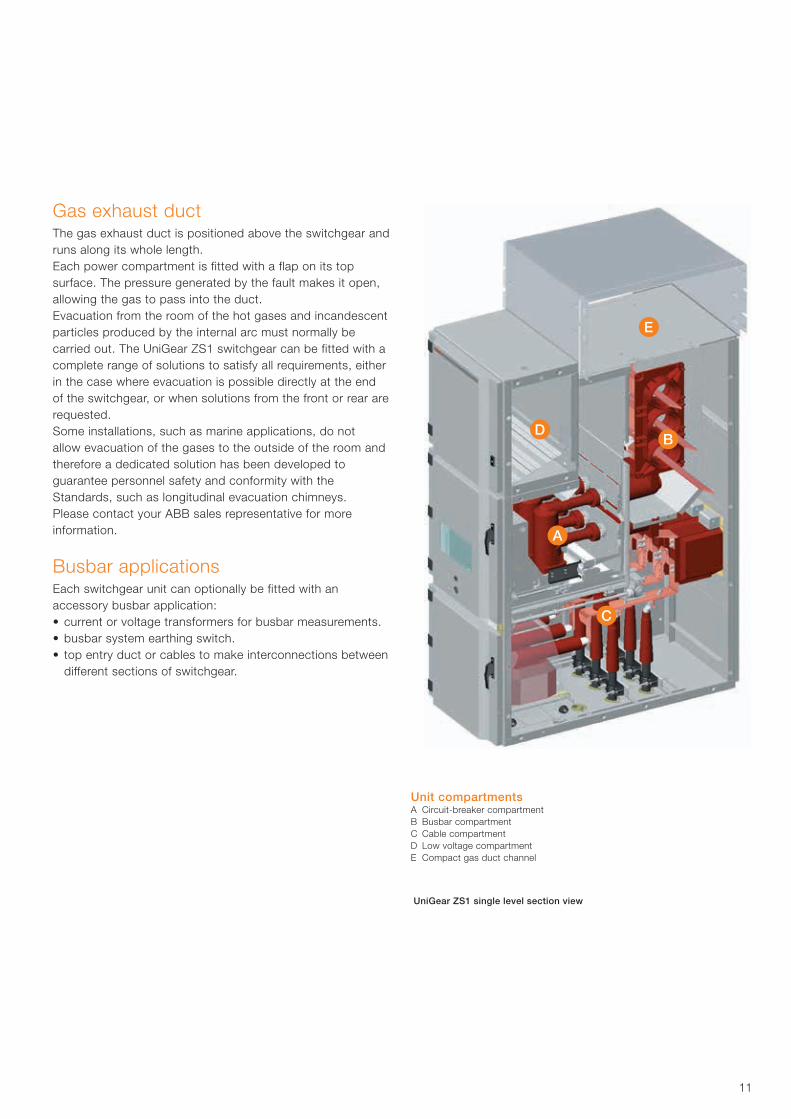
Gas exhaust ductThe gas exhaust duct is positioned above the switchgear andruns along its whole length.Each power compartment is fitted with a flap on its topsurface. The pressure generated by the fault makes it open,allowing the gas to pass into the duct.Evacuation from the room of the hot gases and incandescentparticles produced by the internal arc must normally becarried out. The UniGear ZS1 switchgear can be fitted with acomplete range of solutions to satisfy all requirements, eitherin the case where evacuation is possible directly at the endof the switchgear, or when solutions from the front or rear arerequested.Some installations, such as marine applications, do notallow evacuation of the gases to the outside of the room andtherefore a dedicated solution has been developed toguarantee personnel safety and conformity with theStandards, such as longitudinal evacuation chimneys.Please contact your ABB sales representative for moreinformation.
Busbar applicationsEach switchgear unit can optionally be fitted with anaccessory busbar application:• current or voltage transformers for busbar measurements.• busbar system earthing switch.• top entry duct or cables to make interconnections between
different sections of switchgear.
Unit compartmentsA Circuit-breaker compartmentB Busbar compartmentC Cable compartmentD Low voltage compartmentE Compact gas duct channel
UniGear ZS1 single level section view
12
The UniGear ZS1 switchgear has undergone all the testsrequired by the international (IEC) Standards and localStandards organizations (for example, the Chinese GB/DL and Russian GOST standards).In addition, the tests required by the main shippingregisters (LR, DNV, RINA, BV and GL) have been carried out for use of the switchgear in marine installations.As indicated in these standards, the tests were carried out on the switchgear units considered most sensitive to the effects of the tests and therefore the results were extended across the whole range.Each switchgear unit is subjected to routine tests in the factory before delivery.These tests are intended to provide a functional check of the switchgear based on the specific characteristics of each installation.
IEC type tests • Short-time and peak withstand current• Temperature rise• Internal arc capability• Dielectric test• Making and breaking capacity of circuit-breaker and
contactors• Earthing switch making capacity• Mechanical operations of circuit-breaker and earthing
switch• IP protectiondegree
IEC routine factory tests • Visual inspection and check• Mechanical sequence operations• Cabling check• Electrical sequence operations• Power frequency withstand voltage• Measurement of the resistance of the main circuits• Secondary insulation test
Special type tests required by shipping registers for marine application • High ambient temperatures (+ 45 °C)• Inclination• Vibration
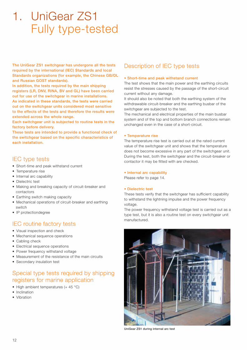
UniGear ZS1 during internal arc test
Description of IEC type tests
• Short-time and peak withstand currentThe test shows that the main power and the earthing circuits resist the stresses caused by the passage of the short-circuit current without any damage.It should also be noted that both the earthing system of the withdrawable circuit-breaker and the earthing busbar of the switchgear are subjected to the test.The mechanical and electrical properties of the main busbar system and of the top and bottom branch connections remain unchanged even in the case of a short-circuit.
• Temperature riseThe temperature rise test is carried out at the rated current value of the switchgear unit and shows that the temperature does not become excessive in any part of the switchgear unit.During the test, both the switchgear and the circuit-breaker or contactor it may be fitted with are checked.
• Internal arc capabilityPlease refer to page 14.
• Dielectric testThese tests verify that the switchgear has sufficient capability to withstand the lightning impulse and the power frequency voltage.The power frequency withstand voltage test is carried out as a type test, but it is also a routine test on every switchgear unit manufactured.
1. UniGear ZS1 Fully type-tested
13
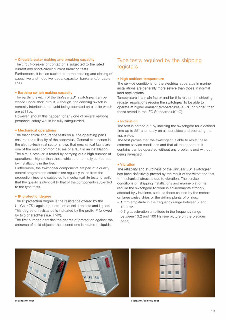
Inclination test Vibration/seismic test
Type tests required by the shipping registers
• High ambient temperatureThe service conditions for the electrical apparatus in marine installations are generally more severe than those in normal land applications.Temperature is a main factor and for this reason the shipping register regulations require the switchgear to be able to operate at higher ambient temperatures (45 °C or higher) than those stated in the IEC Standards (40 °C).
• InclinationThe test is carried out by inclining the switchgear for a defined time up to 25° alternately on all four sides and operating the apparatus.The test proves that the switchgear is able to resist these extreme service conditions and that all the apparatus it contains can be operated without any problems and without being damaged.
• VibrationThe reliability and sturdiness of the UniGear ZS1 switchgear has been definitively proved by the result of the withstand test to mechanical stresses due to vibration. The serviceconditions on shipping installations and marine platforms require the switchgear to work in environments strongly affected by vibrations, such as those caused by the motors on large cruise ships or the drilling plants of oil rigs.– 1 mm amplitude in the frequency range between 2 and
13.2 Hz.– 0.7 g acceleration amplitude in the frequency range
between 13.2 and 100 Hz (see picture on the previous page).
• Circuit-breaker making and breaking capacityThe circuit-breaker or contactor is subjected to the rated current and short-circuit current breaking tests.Furthermore, it is also subjected to the opening and closing of capacitive and inductive loads, capacitor banks and/or cable lines. • Earthing switch making capacityThe earthing switch of the UniGear ZS1 switchgear can be closed under short-circuit. Although, the earthing switch is normally interlocked to avoid being operated on circuits which are still live.However, should this happen for any one of several reasons, personnel safety would be fully safeguarded.
• Mechanical operationsThe mechanical endurance tests on all the operating parts ensures the reliability of the apparatus. General experience in the electro-technical sector shows that mechanical faults are one of the most common causes of a fault in an installation.The circuit-breaker is tested by carrying out a high number of operations - higher than those which are normally carried out by installations in the filed.Furthermore, the switchgear components are part of a qualitycontrol program and samples are regularly taken from the production lines and subjected to mechanical life tests to verify that the quality is identical to that of the components subjected to the type tests.
• IP protectiondegreeThe IP protection degree is the resistance offered by the UniGear ZS1 against penetration of solid objects and liquids.This degree of resistance is indicated by the prefix IP followed by two charachters (i.e. IP4X).The first number identifies the degree of protection against theentrance of solid objects, the second one is related to liquids.
14
When developing modern medium voltage switchgear, personnel safety must necessarily take priority. This is why the UniGear ZS1 switchgear has been designed and tested to withstand an internal arc due to a short-circuit current of the same current level as the maximum short-time withstand level.The tests show that the metal housing of UniGear ZS1 switchgear is able to protect personnel near the switchgear in the case of a fault which evolves as far as striking an internal arc.
An internal arc is a highly unlikely fault, although it can theoretically be caused by various factors, such as:• Insulation defects due to quality deterioration of the
components. The reasons can be adverse environmental conditions and a highly polluted atmosphere.
• Overvoltages of atmospheric origin or generated by the operation of a component.
• Inadequate training of the personnel in charge of the installation.
• Breakage or tampering of the safety interlocks.• Overheating of the contact area, due to the presence
of corrosive agents or when the connections are not sufficiently tightened.
• Entry of small animals into the switchgear (i.e. through cable entrance).
• Material left behind inside the switchgear during maintenance activities.
The characteristics of the UniGear ZS1 switchgear notably reduce the incidence of these causes for faults, but some of them may not be eliminated completely.The energy produced by the internal arc causes the following phenomena:• Increase in the internal pressure.• Increase in temperature.• Visual and acoustic effects.• Mechanical stresses on the switchgear structure.• Melting, decomposition and evaporation of materials.
Unless suitably protected, these phenomena have very serious consequences for the personnel, such as wounds (due to the shock wave, flying parts and the doors opening) and burns (due to emission of hot gases).The internal arc test verifies that the compartment doors remain closed and that no components are ejected from the switchgear even when subjected to very high pressures, and that no flames or incandescent gases penetrate, thereby ensuring safety of the personnel near the switchgear.
The test also ensure that no holes are produced in external accessible parts of the housing, and finally, that all the connections to the earthing circuit remain intact, hence guaranteeing the safety of personnel who may access the switchgear after the fault.The IEC 62271-200 Standard describes the methods to be used for carrying out the test and the criteria which the switchgear must conform to.The UniGear ZS1 switchgear fully conforms to all the five criteria indicated by the IEC standards.
The IAC classification is proved by the test according to the following designations:• General: classification IAC (Internal Arc Classified)• Accessibility: A, B or C (switchgear accessible to authorized
personnel only (A), to all (B), not accessible due to installation (C)
• F, L, R: access from the front (F – Front), from the sides (L – Lateral) and from the rear (R – rear).
• Test values: test current in kiloamperes (kA), and duration in seconds (s).
The parameters of each specific plant mean that evacuation of the hot gases and incandescent particles must be checked very carefully in order to ensure and maintain personnel safety.
Fault limiting systemsThe structure of the UniGear ZS1 switchgear offers complete passive type protection against the effects of a fault due to an internal arc for a time of 1 second up to 50 kA.ABB has also developed excellent active protection systemswhich allow very important objectives to be achieved:• Detection and extinction of the fault, normally in less than
100 ms, which improves network stability.• Limitation of damage on the apparatus.• Limitation of outage time for the switchgear unit.For active protection against an internal arc, devices consisting of various types of sensors can be installed in the various compartments, which detect the immediate outburst of the fault and carry out selective tripping of the circuit-breakers.The fault limiting systems are based on sensors which use the pressure or light generated by the arc fault as trigger for fault disconnection.
1. UniGear ZS1 Safety
15
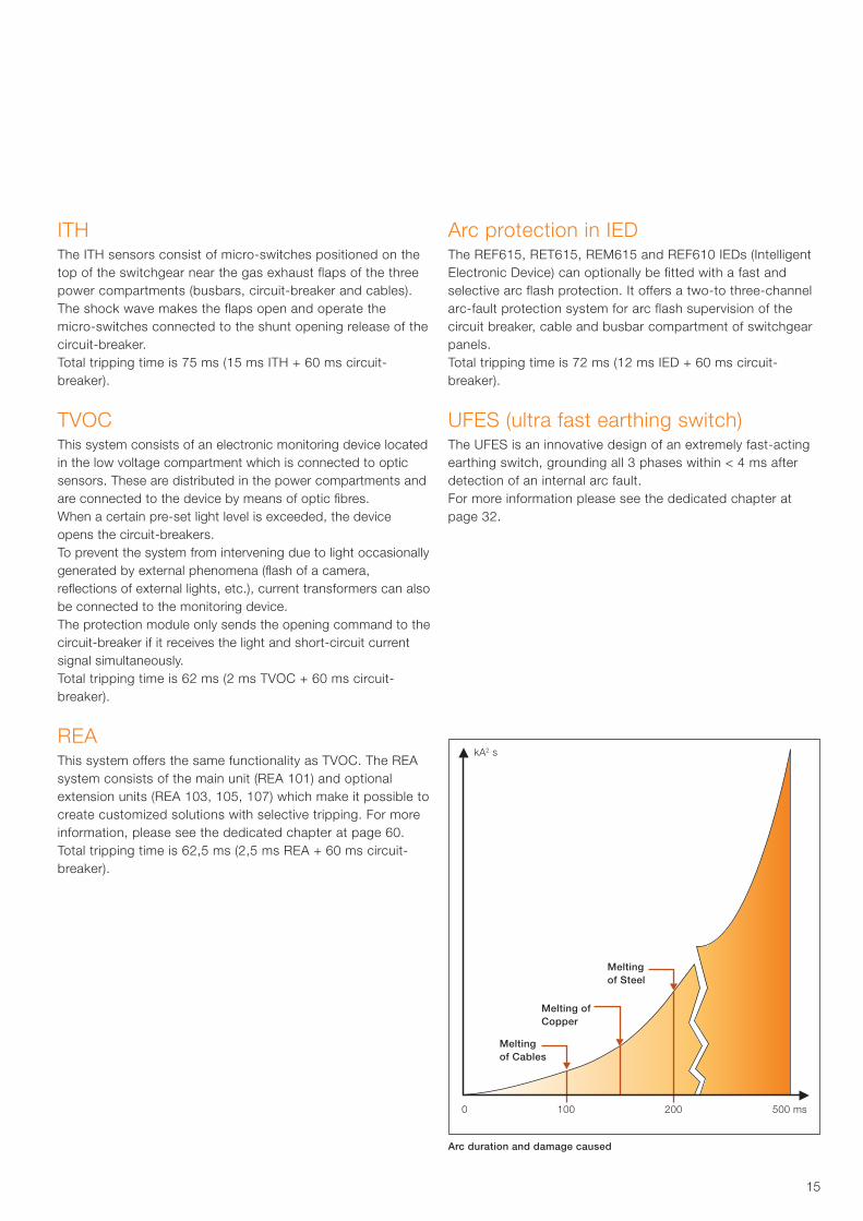
Melting of Steel
Melting of Copper
Melting of Cables
0 100 200 500 ms
kA2 s
ITHThe ITH sensors consist of micro-switches positioned on thetop of the switchgear near the gas exhaust flaps of the threepower compartments (busbars, circuit-breaker and cables).The shock wave makes the flaps open and operate the micro-switches connected to the shunt opening release of the circuit-breaker.Total tripping time is 75 ms (15 ms ITH + 60 ms circuit-breaker).
TVOCThis system consists of an electronic monitoring device located in the low voltage compartment which is connected to optic sensors. These are distributed in the power compartments and are connected to the device by means of optic fibres.When a certain pre-set light level is exceeded, the device opens the circuit-breakers.To prevent the system from intervening due to light occasionally generated by external phenomena (flash of a camera, reflections of external lights, etc.), current transformers can also be connected to the monitoring device.The protection module only sends the opening command to the circuit-breaker if it receives the light and short-circuit current signal simultaneously.Total tripping time is 62 ms (2 ms TVOC + 60 ms circuit-breaker).
REA This system offers the same functionality as TVOC. The REA system consists of the main unit (REA 101) and optional extension units (REA 103, 105, 107) which make it possible to create customized solutions with selective tripping. For more information, please see the dedicated chapter at page 60.Total tripping time is 62,5 ms (2,5 ms REA + 60 ms circuit-breaker).
Arc duration and damage caused
Arc protection in IEDThe REF615, RET615, REM615 and REF610 IEDs (Intelligent Electronic Device) can optionally be fitted with a fast and selective arc flash protection. It offers a two-to three-channel arc-fault protection system for arc flash supervision of the circuit breaker, cable and busbar compartment of switchgear panels.Total tripping time is 72 ms (12 ms IED + 60 ms circuit-breaker).
UFES (ultra fast earthing switch)The UFES is an innovative design of an extremely fast-acting earthing switch, grounding all 3 phases within < 4 ms after detection of an internal arc fault.For more information please see the dedicated chapter at page 32.
16
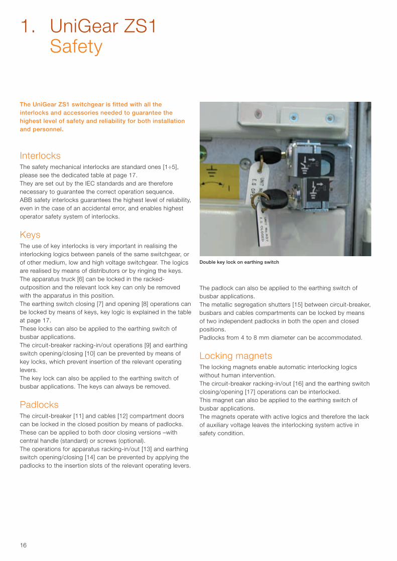
Double key lock on earthing switch
The UniGear ZS1 switchgear is fitted with all the interlocks and accessories needed to guarantee the highest level of safety and reliability for both installation and personnel.
InterlocksThe safety mechanical interlocks are standard ones [1÷5], please see the dedicated table at page 17.They are set out by the IEC standards and are therefore necessary to guarantee the correct operation sequence.ABB safety interlocks guarantees the highest level of reliability, even in the case of an accidental error, and enables highest operator safety system of interlocks.
KeysThe use of key interlocks is very important in realising the interlocking logics between panels of the same switchgear, or of other medium, low and high voltage switchgear. The logics are realised by means of distributors or by ringing the keys.The apparatus truck [6] can be locked in the racked-outposition and the relevant lock key can only be removed with the apparatus in this position.The earthing switch closing [7] and opening [8] operations can be locked by means of keys, key logic is explained in the table at page 17.These locks can also be applied to the earthing switch of busbar applications.The circuit-breaker racking-in/out operations [9] and earthing switch opening/closing [10] can be prevented by means of key locks, which prevent insertion of the relevant operating levers.The key lock can also be applied to the earthing switch of busbar applications. The keys can always be removed.
PadlocksThe circuit-breaker [11] and cables [12] compartment doors can be locked in the closed position by means of padlocks.These can be applied to both door closing versions –with central handle (standard) or screws (optional).The operations for apparatus racking-in/out [13] and earthing switch opening/closing [14] can be prevented by applying the padlocks to the insertion slots of the relevant operating levers.
The padlock can also be applied to the earthing switch of busbar applications.The metallic segregation shutters [15] between circuit-breaker, busbars and cables compartments can be locked by means of two independent padlocks in both the open and closed positions.Padlocks from 4 to 8 mm diameter can be accommodated.
Locking magnetsThe locking magnets enable automatic interlocking logics without human intervention.The circuit-breaker racking-in/out [16] and the earthing switch closing/opening [17] operations can be interlocked. This magnet can also be applied to the earthing switch of busbar applications.The magnets operate with active logics and therefore the lack of auxiliary voltage leaves the interlocking system active in safety condition.
1. UniGear ZS1 Safety
17
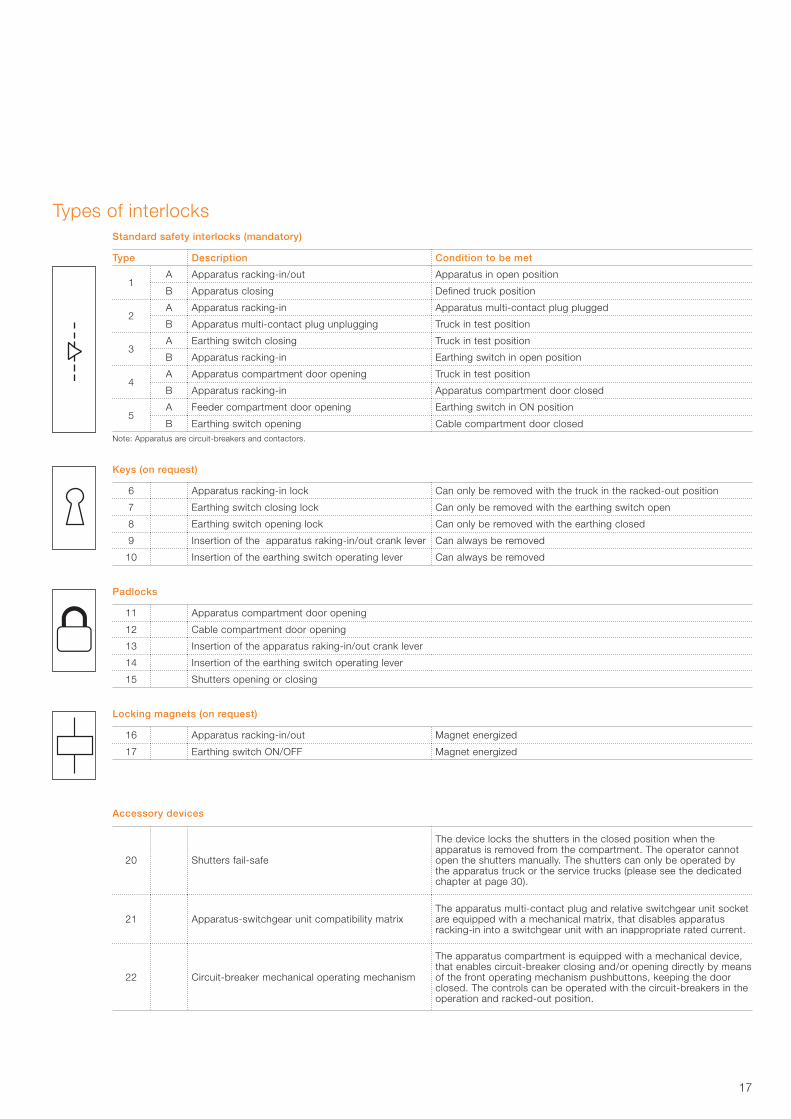
Standard safety interlocks (mandatory)
Type Description Condition to be met
1A Apparatus racking-in/out Apparatus in open position
B Apparatus closing Defined truck position
2A Apparatus racking-in Apparatus multi-contact plug plugged
B Apparatus multi-contact plug unplugging Truck in test position
3A Earthing switch closing Truck in test position
B Apparatus racking-in Earthing switch in open position
4A Apparatus compartment door opening Truck in test position
B Apparatus racking-in Apparatus compartment door closed
5A Feeder compartment door opening Earthing switch in ON position
B Earthing switch opening Cable compartment door closedNote: Apparatus are circuit-breakers and contactors.
Keys (on request)
6 Apparatus racking-in lock Can only be removed with the truck in the racked-out position
7 Earthing switch closing lock Can only be removed with the earthing switch open
8 Earthing switch opening lock Can only be removed with the earthing closed
9 Insertion of the apparatus raking-in/out crank lever Can always be removed
10 Insertion of the earthing switch operating lever Can always be removed
Padlocks
11 Apparatus compartment door opening
12 Cable compartment door opening
13 Insertion of the apparatus raking-in/out crank lever
14 Insertion of the earthing switch operating lever
15 Shutters opening or closing
Locking magnets (on request)
16 Apparatus racking-in/out Magnet energized
17 Earthing switch ON/OFF Magnet energized
Accessory devices
20 Shutters fail-safe
The device locks the shutters in the closed position when the apparatus is removed from the compartment. The operator cannot open the shutters manually. The shutters can only be operated by the apparatus truck or the service trucks (please see the dedicated chapter at page 30).
21 Apparatus-switchgear unit compatibility matrixThe apparatus multi-contact plug and relative switchgear unit socket are equipped with a mechanical matrix, that disables apparatus racking-in into a switchgear unit with an inappropriate rated current.
22 Circuit-breaker mechanical operating mechanism
The apparatus compartment is equipped with a mechanical device, that enables circuit-breaker closing and/or opening directly by means of the front operating mechanism pushbuttons, keeping the door closed. The controls can be operated with the circuit-breakers in the operation and racked-out position.
Types of interlocks
18
1. UniGear ZS1 Vacuum circuit-breaker
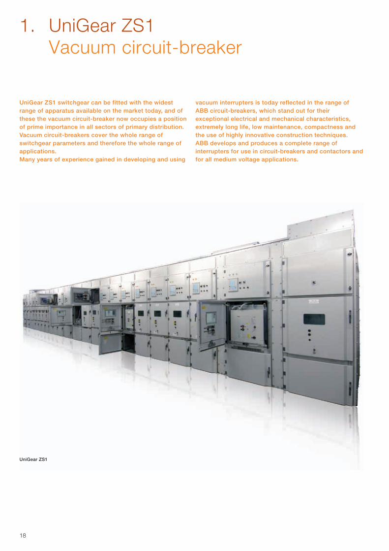
UniGear ZS1 switchgear can be fitted with the widest range of apparatus available on the market today, and of these the vacuum circuit-breaker now occupies a position of prime importance in all sectors of primary distribution.Vacuum circuit-breakers cover the whole range of switchgear parameters and therefore the whole range of applications.Many years of experience gained in developing and using
vacuum interrupters is today reflected in the range ofABB circuit-breakers, which stand out for their exceptional electrical and mechanical characteristics, extremely long life, low maintenance, compactness and the use of highly innovative construction techniques.ABB develops and produces a complete range of interrupters for use in circuit-breakers and contactors and for all medium voltage applications.
UniGear ZS1
19
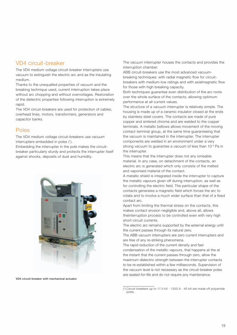
VD4 circuit-breakerThe VD4 medium voltage circuit-breaker interrupters use vacuum to extinguish the electric arc and as the insulating medium.Thanks to the unequalled properties of vacuum and the breaking technique used, current interruption takes place without arc chopping and without overvoltages. Restoration of the dielectric properties following interruption is extremely rapid.The VD4 circuit-breakers are used for protection of cables, overhead lines, motors, transformers, generators and capacitor banks.
PolesThe VD4 medium voltage circuit-breakers use vacuum interrupters embedded in poles (1).Embedding the interrupter in the pole makes the circuit-breaker particularly sturdy and protects the interrupter itself against shocks, deposits of dust and humidity.
The vacuum interrupter houses the contacts and provides theinterruption chamber.ABB circuit-breakers use the most advanced vacuum-breaking techniques: with radial magnetic flow for circuit-breakers with medium-low ratings and with axialmagnetic flow for those with high breaking capacity.Both techniques guarantee even distribution of the arc roots over the whole surface of the contacts, allowing optimum performance at all current values.The structure of a vacuum interrupter is relatively simple. The housing is made up of a ceramic insulator closed at the ends by stainless steel covers. The contacts are made of pure copper and sintered chrome and are welded to the copper terminals. A metallic bellows allows movement of the moving contact-terminal group, at the same time guaranteeing that the vacuum is maintained in the interrupter. The interrupter components are welded in an environment under a very strong vacuum to guarantee a vacuum of less than 10-5 Pa in the interrupter. This means that the interrupter does not any ionisable material. In any case, on detachment of the contacts, an electric arc is generated which only consists of the melted and vaporised material of the contact.A metallic shield is integrated inside the interrupter to capture the metallic vapours given off during interruption, as well as for controlling the electric field. The particular shape of the contacts generates a magnetic field which forces the arc to rotate and to involve a much wider surface than that of a fixed contact arc.Apart from limiting the thermal stress on the contacts, this makes contact erosion negligible and, above all, allows theinterruption process to be controlled even with very high short-circuit currents. The electric arc remains supported by the external energy until the current passes through its natural zero.The ABB vacuum interrupters are zero current interrupters and are free of any re-striking phenomena.The rapid reduction of the current density and fastcondensation of the metallic vapours, that happens at the at the instant that the current passes through zero, allow the maximum dielectric strength between the interrupter contacts to be re-established within a few milliseconds. Supervision of the vacuum level is not necessary as the circuit-breaker poles are sealed-for-life and do not require any maintenance.
(1) Circuit-breakers up to 17.5 kV - 1250 A - 40 kA are made off polyamide poles.
VD4 circuit-breaker with mechanical actuator
20
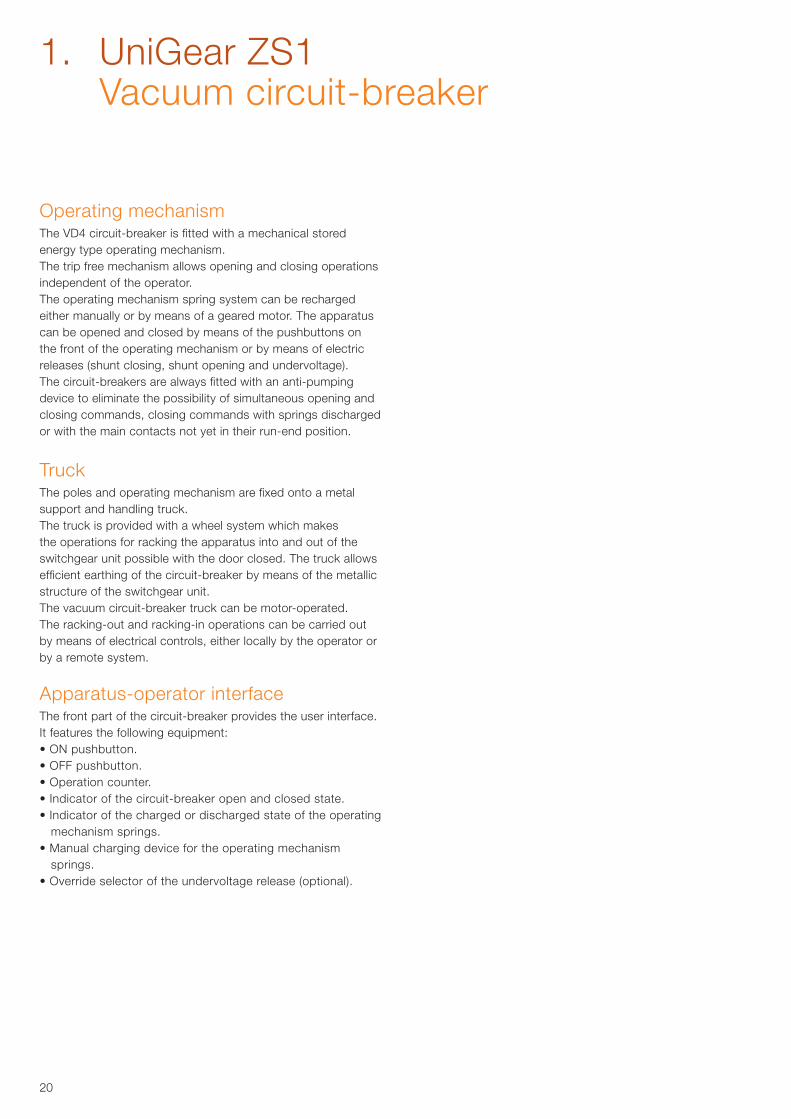
Operating mechanismThe VD4 circuit-breaker is fitted with a mechanical stored energy type operating mechanism.The trip free mechanism allows opening and closing operations independent of the operator.The operating mechanism spring system can be recharged either manually or by means of a geared motor. The apparatus can be opened and closed by means of the pushbuttons on the front of the operating mechanism or by means of electric releases (shunt closing, shunt opening and undervoltage).The circuit-breakers are always fitted with an anti-pumping device to eliminate the possibility of simultaneous opening and closing commands, closing commands with springs discharged or with the main contacts not yet in their run-end position.
TruckThe poles and operating mechanism are fixed onto a metal support and handling truck.The truck is provided with a wheel system which makes the operations for racking the apparatus into and out of the switchgear unit possible with the door closed. The truck allows efficient earthing of the circuit-breaker by means of the metallic structure of the switchgear unit.The vacuum circuit-breaker truck can be motor-operated.The racking-out and racking-in operations can be carried out by means of electrical controls, either locally by the operator or by a remote system.
Apparatus-operator interfaceThe front part of the circuit-breaker provides the user interface.It features the following equipment:• ON pushbutton.• OFF pushbutton.• Operation counter.• Indicator of the circuit-breaker open and closed state.• Indicator of the charged or discharged state of the operating
mechanism springs.• Manual charging device for the operating mechanism
springs.• Override selector of the undervoltage release (optional).
1. UniGear ZS1 Vacuum circuit-breaker
21
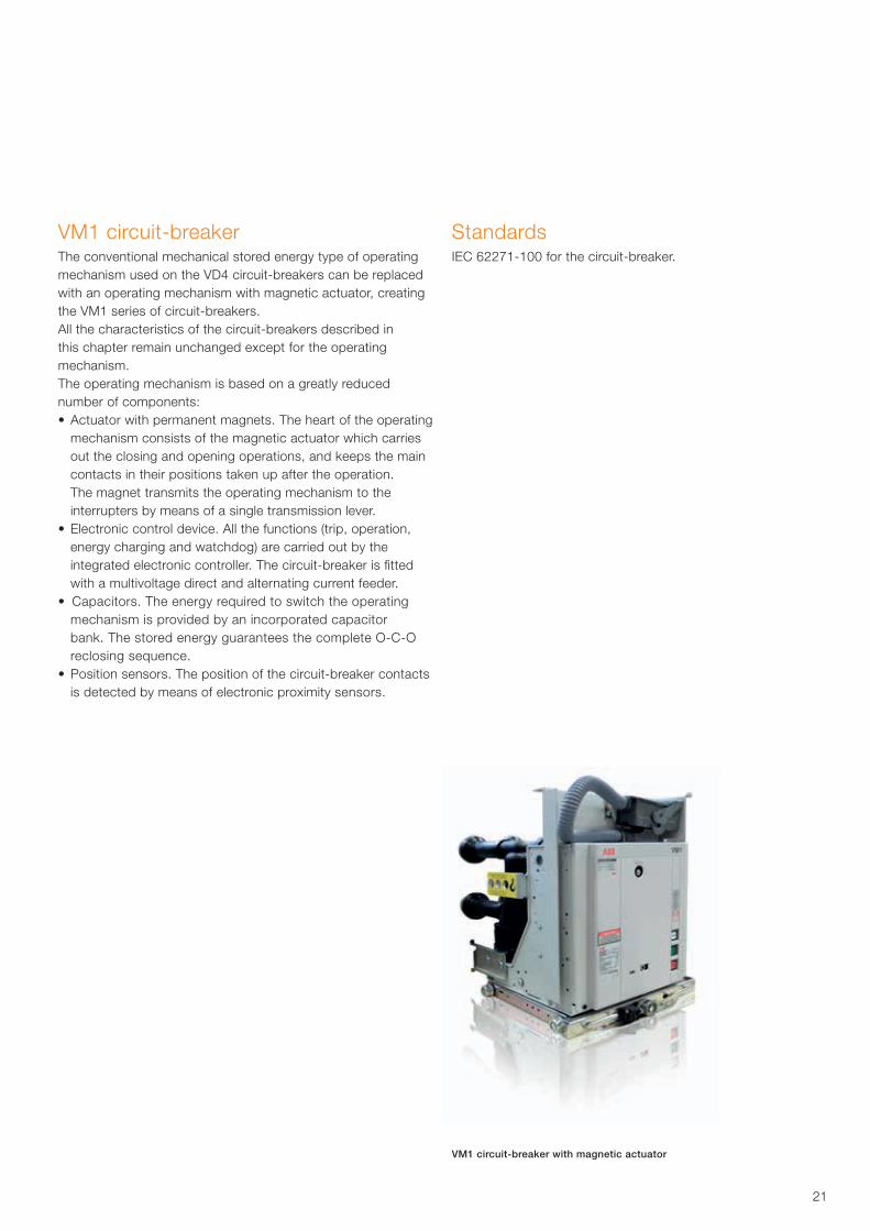
VM1 circuit-breaker The conventional mechanical stored energy type of operatingmechanism used on the VD4 circuit-breakers can be replaced with an operating mechanism with magnetic actuator, creating the VM1 series of circuit-breakers.All the characteristics of the circuit-breakers described in this chapter remain unchanged except for the operating mechanism.The operating mechanism is based on a greatly reduced number of components:• Actuator with permanent magnets. The heart of the operating
mechanism consists of the magnetic actuator which carries out the closing and opening operations, and keeps the main contacts in their positions taken up after the operation. The magnet transmits the operating mechanism to the interrupters by means of a single transmission lever.
• Electronic control device. All the functions (trip, operation, energy charging and watchdog) are carried out by the integrated electronic controller. The circuit-breaker is fitted with a multivoltage direct and alternating current feeder.
• Capacitors. The energy required to switch the operating mechanism is provided by an incorporated capacitor bank. The stored energy guarantees the complete O-C-O reclosing sequence.
• Position sensors. The position of the circuit-breaker contacts is detected by means of electronic proximity sensors.
Standards IEC 62271-100 for the circuit-breaker.
VM1 circuit-breaker with magnetic actuator
22
1. UniGear ZS1 VD4G – Vacuum circuit-breaker for
generator switching applications
The worldwide increasing energy demand is covered more and more by decentralized power plants and renewable resources of small unit size. As the generated energy is fed into the grid by step-up transformers and MV distribution boards, VD4G offers a reliable and economical solution to protect the power plants assets.
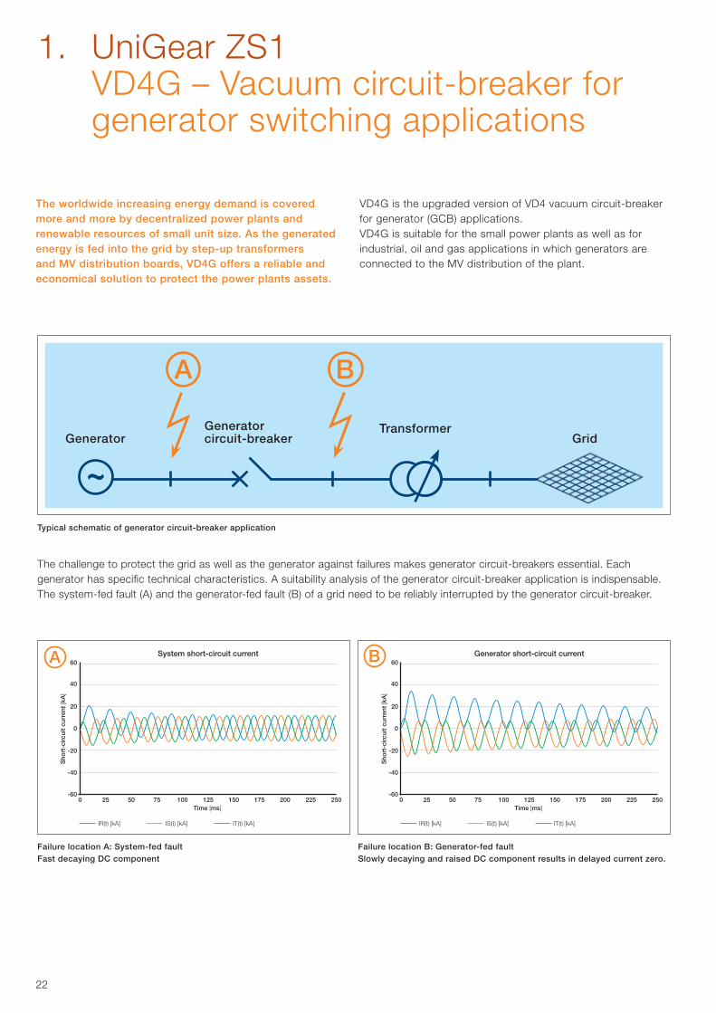
The challenge to protect the grid as well as the generator against failures makes generator circuit-breakers essential. Each generator has specific technical characteristics. A suitability analysis of the generator circuit-breaker application is indispensable. The system-fed fault (A) and the generator-fed fault (B) of a grid need to be reliably interrupted by the generator circuit-breaker.
Typical schematic of generator circuit-breaker application
Transformer
VD4G is the upgraded version of VD4 vacuum circuit-breaker for generator (GCB) applications. VD4G is suitable for the small power plants as well as for industrial, oil and gas applications in which generators are connected to the MV distribution of the plant.
System short-circuit current
Time [ms]
Sho
rt-c
ircui
t cu
rren
t [k
A]
0 25 50 75 100 125 150 175 200 225 250
-20
0
20
40
60
-40
-60
IR(t) [kA] IS(t) [kA] IT(t) [kA]
Generator short-circuit current
Time [ms]0 25 50 75 100 125 150 175 200 225 250
-20
0
20
40
60
-40
-60
IR(t) [kA] IS(t) [kA] IT(t) [kA]
Sho
rt-c
ircui
t cu
rren
t [k
A]
Failure location A: System-fed faultFast decaying DC component
Failure location B: Generator-fed faultSlowly decaying and raised DC component results in delayed current zero.
23
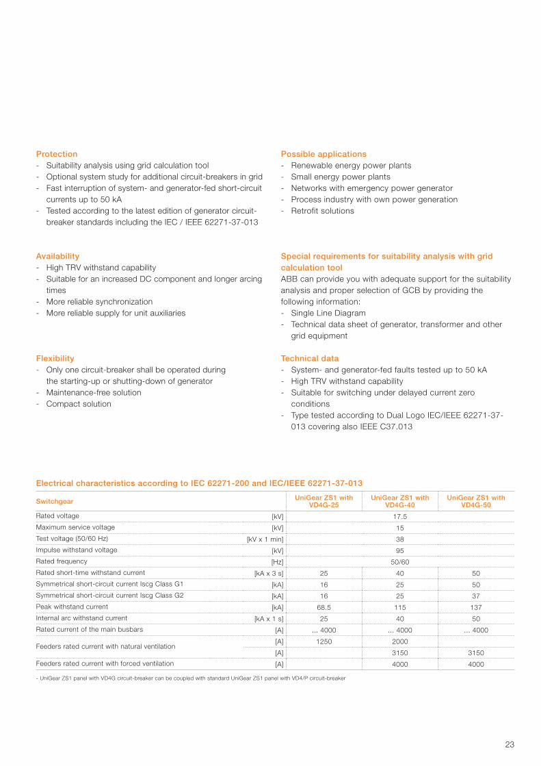
Electrical characteristics according to IEC 62271-200 and IEC/IEEE 62271-37-013
Switchgear UniGear ZS1 with VD4G-25
UniGear ZS1 with VD4G-40
UniGear ZS1 with VD4G-50
Rated voltage [kV] 17.5
Maximum service voltage [kV] 15
Test voltage (50/60 Hz) [kV x 1 min] 38
Impulse withstand voltage [kV] 95
Rated frequency [Hz] 50/60
Rated short-time withstand current [kA x 3 s] 25 40 50
Symmetrical short-circuit current Iscg Class G1 [kA] 16 25 50
Symmetrical short-circuit current Iscg Class G2 [kA] 16 25 37
Peak withstand current [kA] 68.5 115 137
Internal arc withstand current [kA x 1 s] 25 40 50
Rated current of the main busbars [A] ... 4000 ... 4000 ... 4000
Feeders rated current with natural ventilation[A] 1250 2000
[A] 3150 3150
Feeders rated current with forced ventilation [A] 4000 4000
- UniGear ZS1 panel with VD4G circuit-breaker can be coupled with standard UniGear ZS1 panel with VD4/P circuit-breaker
Protection - Suitability analysis using grid calculation tool - Optional system study for additional circuit-breakers in grid - Fast interruption of system- and generator-fed short-circuit
currents up to 50 kA - Tested according to the latest edition of generator circuit-
breaker standards including the IEC / IEEE 62271-37-013
Availability - High TRV withstand capability - Suitable for an increased DC component and longer arcing
times - More reliable synchronization - More reliable supply for unit auxiliaries
Flexibility - Only one circuit-breaker shall be operated during
the starting-up or shutting-down of generator - Maintenance-free solution - Compact solution
Possible applications - Renewable energy power plants - Small energy power plants - Networks with emergency power generator - Process industry with own power generation - Retrofit solutions
Special requirements for suitability analysis with grid calculation toolABB can provide you with adequate support for the suitability analysis and proper selection of GCB by providing the following information: - Single Line Diagram - Technical data sheet of generator, transformer and other
grid equipment
Technical data - System- and generator-fed faults tested up to 50 kA - High TRV withstand capability - Suitable for switching under delayed current zero
conditions - Type tested according to Dual Logo IEC/IEEE 62271-37-
013 covering also IEEE C37.013
24
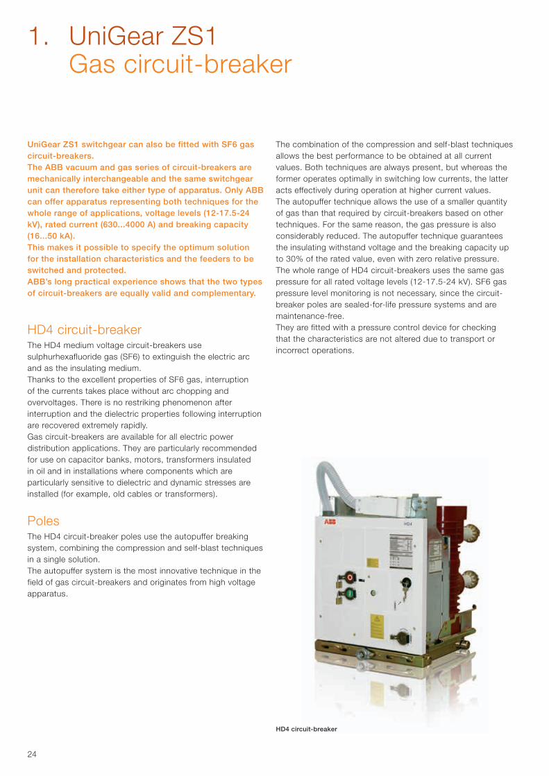
HD4 circuit-breaker
UniGear ZS1 switchgear can also be fitted with SF6 gas circuit-breakers.The ABB vacuum and gas series of circuit-breakers are mechanically interchangeable and the same switchgear unit can therefore take either type of apparatus. Only ABB can offer apparatus representing both techniques for the whole range of applications, voltage levels (12-17.5-24 kV), rated current (630...4000 A) and breaking capacity (16...50 kA).This makes it possible to specify the optimum solution for the installation characteristics and the feeders to be switched and protected.ABB’s long practical experience shows that the two types of circuit-breakers are equally valid and complementary.
HD4 circuit-breakerThe HD4 medium voltage circuit-breakers use sulphurhexafluoride gas (SF6) to extinguish the electric arc and as the insulating medium.Thanks to the excellent properties of SF6 gas, interruption of the currents takes place without arc chopping and overvoltages. There is no restriking phenomenon after interruption and the dielectric properties following interruption are recovered extremely rapidly.Gas circuit-breakers are available for all electric power distribution applications. They are particularly recommended for use on capacitor banks, motors, transformers insulated in oil and in installations where components which are particularly sensitive to dielectric and dynamic stresses are installed (for example, old cables or transformers).
PolesThe HD4 circuit-breaker poles use the autopuffer breaking system, combining the compression and self-blast techniques in a single solution.The autopuffer system is the most innovative technique in the field of gas circuit-breakers and originates from high voltage apparatus.
The combination of the compression and self-blast techniques allows the best performance to be obtained at all current values. Both techniques are always present, but whereas the former operates optimally in switching low currents, the latter acts effectively during operation at higher current values.The autopuffer technique allows the use of a smaller quantity of gas than that required by circuit-breakers based on other techniques. For the same reason, the gas pressure is also considerably reduced. The autopuffer technique guarantees the insulating withstand voltage and the breaking capacity up to 30% of the rated value, even with zero relative pressure.The whole range of HD4 circuit-breakers uses the same gas pressure for all rated voltage levels (12-17.5-24 kV). SF6 gas pressure level monitoring is not necessary, since the circuit-breaker poles are sealed-for-life pressure systems and are maintenance-free.They are fitted with a pressure control device for checking that the characteristics are not altered due to transport or incorrect operations.
1. UniGear ZS1 Gas circuit-breaker
25
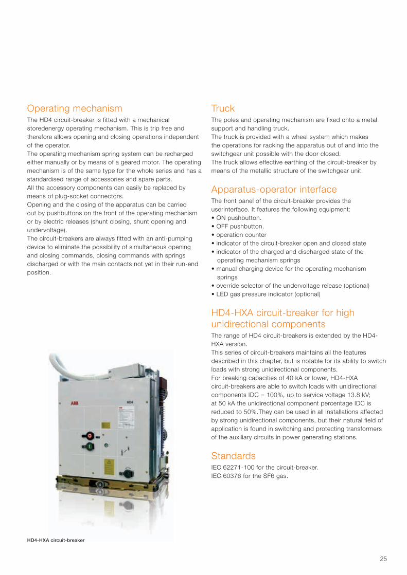
HD4-HXA circuit-breaker
Operating mechanismThe HD4 circuit-breaker is fitted with a mechanical storedenergy operating mechanism. This is trip free and therefore allows opening and closing operations independent of the operator.The operating mechanism spring system can be recharged either manually or by means of a geared motor. The operating mechanism is of the same type for the whole series and has a standardised range of accessories and spare parts.All the accessory components can easily be replaced by means of plug-socket connectors.Opening and the closing of the apparatus can be carried out by pushbuttons on the front of the operating mechanism or by electric releases (shunt closing, shunt opening and undervoltage).The circuit-breakers are always fitted with an anti-pumping device to eliminate the possibility of simultaneous opening and closing commands, closing commands with springs discharged or with the main contacts not yet in their run-end position.
TruckThe poles and operating mechanism are fixed onto a metal support and handling truck.The truck is provided with a wheel system which makes the operations for racking the apparatus out of and into the switchgear unit possible with the door closed.The truck allows effective earthing of the circuit-breaker by means of the metallic structure of the switchgear unit.
Apparatus-operator interfaceThe front panel of the circuit-breaker provides the userinterface. It features the following equipment:• ON pushbutton.• OFF pushbutton.• operation counter• indicator of the circuit-breaker open and closed state• indicator of the charged and discharged state of the
operating mechanism springs• manual charging device for the operating mechanism
springs• override selector of the undervoltage release (optional)• LED gas pressure indicator (optional)
HD4-HXA circuit-breaker for high unidirectional componentsThe range of HD4 circuit-breakers is extended by the HD4-HXA version.This series of circuit-breakers maintains all the featuresdescribed in this chapter, but is notable for its ability to switch loads with strong unidirectional components.For breaking capacities of 40 kA or lower, HD4-HXA circuit-breakers are able to switch loads with unidirectional components IDC = 100%, up to service voltage 13.8 kV; at 50 kA the unidirectional component percentage IDC is reduced to 50%.They can be used in all installations affected by strong unidirectional components, but their natural field of application is found in switching and protecting transformers of the auxiliary circuits in power generating stations.
StandardsIEC 62271-100 for the circuit-breaker.IEC 60376 for the SF6 gas.
26
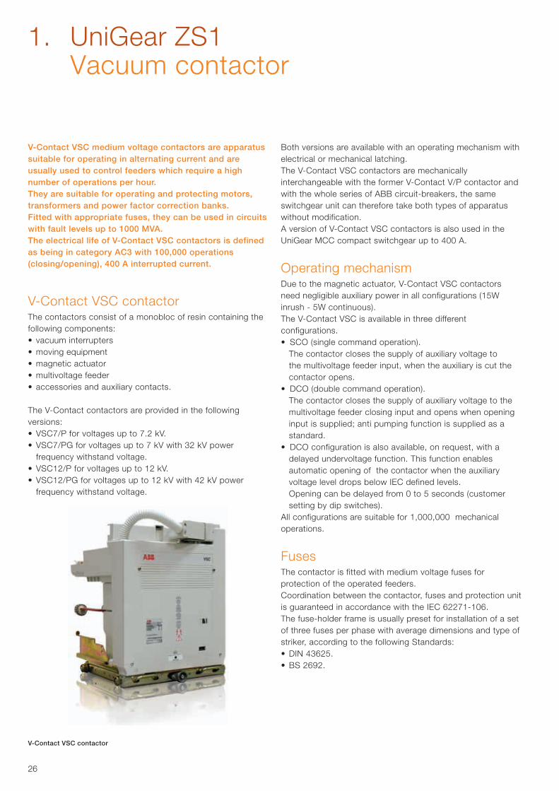
V-Contact VSC medium voltage contactors are apparatus suitable for operating in alternating current and are usually used to control feeders which require a high number of operations per hour.They are suitable for operating and protecting motors, transformers and power factor correction banks. Fitted with appropriate fuses, they can be used in circuits with fault levels up to 1000 MVA.The electrical life of V-Contact VSC contactors is defined as being in category AC3 with 100,000 operations (closing/opening), 400 A interrupted current.
V-Contact VSC contactor The contactors consist of a monobloc of resin containing the following components:• vacuum interrupters• moving equipment• magnetic actuator• multivoltage feeder• accessories and auxiliary contacts.
The V-Contact contactors are provided in the following versions:• VSC7/P for voltages up to 7.2 kV.• VSC7/PG for voltages up to 7 kV with 32 kV power
frequency withstand voltage.• VSC12/P for voltages up to 12 kV.• VSC12/PG for voltages up to 12 kV with 42 kV power
frequency withstand voltage.
Both versions are available with an operating mechanism withelectrical or mechanical latching.The V-Contact VSC contactors are mechanically interchangeable with the former V-Contact V/P contactor andwith the whole series of ABB circuit-breakers, the sameswitchgear unit can therefore take both types of apparatuswithout modification.A version of V-Contact VSC contactors is also used in the UniGear MCC compact switchgear up to 400 A.
Operating mechanismDue to the magnetic actuator, V-Contact VSC contactors need negligible auxiliary power in all configurations (15W inrush - 5W continuous).The V-Contact VSC is available in three different configurations.• SCO (single command operation). The contactor closes the supply of auxiliary voltage to
the multivoltage feeder input, when the auxiliary is cut the contactor opens.
• DCO (double command operation). The contactor closes the supply of auxiliary voltage to the
multivoltage feeder closing input and opens when opening input is supplied; anti pumping function is supplied as a standard.
• DCO configuration is also available, on request, with a delayed undervoltage function. This function enables automatic opening of the contactor when the auxiliary voltage level drops below IEC defined levels.
Opening can be delayed from 0 to 5 seconds (customer setting by dip switches).
All configurations are suitable for 1,000,000 mechanicaloperations.
FusesThe contactor is fitted with medium voltage fuses for protection of the operated feeders.Coordination between the contactor, fuses and protection unit is guaranteed in accordance with the IEC 62271-106. The fuse-holder frame is usually preset for installation of a set of three fuses per phase with average dimensions and type of striker, according to the following Standards:• DIN 43625.• BS 2692.
V-Contact VSC contactor
1. UniGear ZS1 Vacuum contactor
27
Maximum load currents of the fuses
Feeder Transformers Motors Capacitors
Rated voltage Fuse Maximum load Fuse Maximum load Fuse Maximum load
3.6 kV 200A 160A 315A 250A 450A 360A
7.2 kV 200A 160A 315A 250A 355A 285A
12 kV 200A 160A 200A 160A 200A 160A
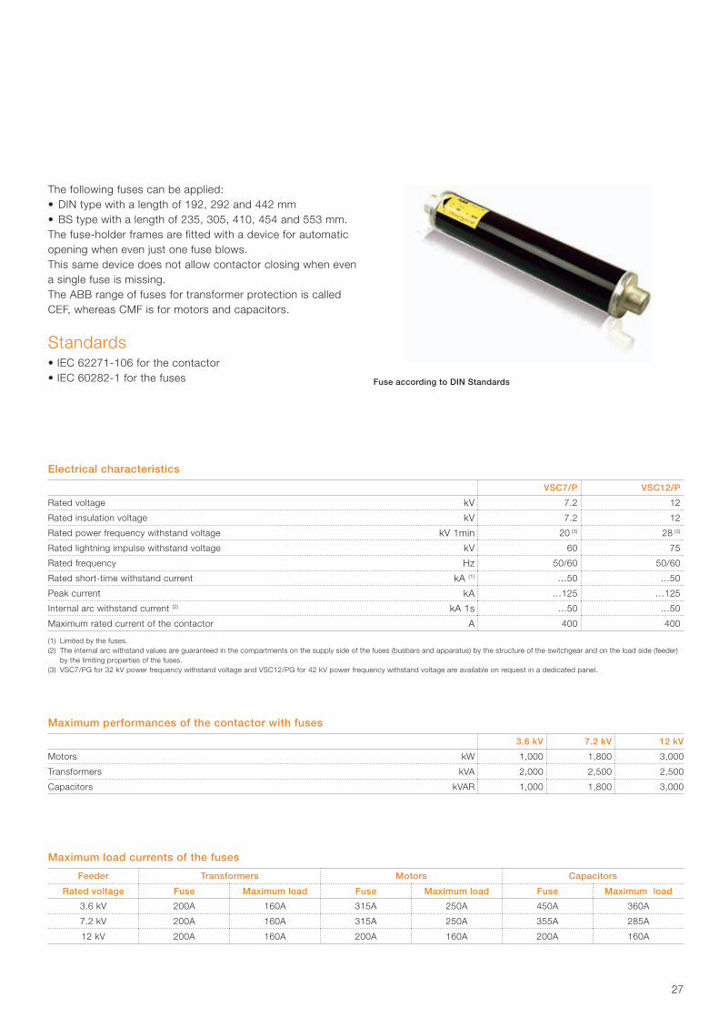
Fuse according to DIN Standards
Electrical characteristics
VSC7/P VSC12/P
Rated voltage kV 7.2 12
Rated insulation voltage kV 7.2 12
Rated power frequency withstand voltage kV 1min 20 (3) 28 (3)
Rated lightning impulse withstand voltage kV 60 75
Rated frequency Hz 50/60 50/60
Rated short-time withstand current kA (1) …50 …50
Peak current kA …125 …125
Internal arc withstand current (2) kA 1s …50 …50
Maximum rated current of the contactor A 400 400
(1) Limited by the fuses.(2) The internal arc withstand values are guaranteed in the compartments on the supply side of the fuses (busbars and apparatus) by the structure of the switchgear and on the load side (feeder) by the limiting properties of the fuses.(3) VSC7/PG for 32 kV power frequency withstand voltage and VSC12/PG for 42 kV power frequency withstand voltage are available on request in a dedicated panel.
Maximum performances of the contactor with fuses
3.6 kV 7.2 kV 12 kV
Motors kW 1,000 1,800 3,000
Transformers kVA 2,000 2,500 2,500
Capacitors kVAR 1,000 1,800 3,000
The following fuses can be applied:• DIN type with a length of 192, 292 and 442 mm• BS type with a length of 235, 305, 410, 454 and 553 mm.The fuse-holder frames are fitted with a device for automatic opening when even just one fuse blows. This same device does not allow contactor closing when even a single fuse is missing.The ABB range of fuses for transformer protection is called CEF, whereas CMF is for motors and capacitors.
Standards• IEC 62271-106 for the contactor• IEC 60282-1 for the fuses
28
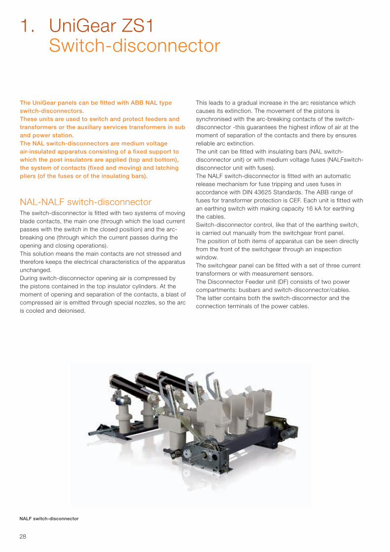
The UniGear panels can be fitted with ABB NAL type switch-disconnectors.These units are used to switch and protect feeders andtransformers or the auxiliary services transformers in sub and power station.The NAL switch-disconnectors are medium voltage air-insulated apparatus consisting of a fixed support to which the post insulators are applied (top and bottom), the system of contacts (fixed and moving) and latching pliers (of the fuses or of the insulating bars).
NAL-NALF switch-disconnectorThe switch-disconnector is fitted with two systems of movingblade contacts, the main one (through which the load current passes with the switch in the closed position) and the arc-breaking one (through which the current passes during the opening and closing operations).This solution means the main contacts are not stressed and therefore keeps the electrical characteristics of the apparatus unchanged.During switch-disconnector opening air is compressed by the pistons contained in the top insulator cylinders. At the moment of opening and separation of the contacts, a blast of compressed air is emitted through special nozzles, so the arc is cooled and deionised.
This leads to a gradual increase in the arc resistance whichcauses its extinction. The movement of the pistons issynchronised with the arc-breaking contacts of the switch-disconnector -this guarantees the highest inflow of air at themoment of separation of the contacts and there by ensuresreliable arc extinction.The unit can be fitted with insulating bars (NAL switch-disconnector unit) or with medium voltage fuses (NALFswitch-disconnector unit with fuses).The NALF switch-disconnector is fitted with an automatic release mechanism for fuse tripping and uses fuses in accordance with DIN 43625 Standards. The ABB range of fuses for transformer protection is CEF. Each unit is fitted with an earthing switch with making capacity 16 kA for earthing the cables.Switch-disconnector control, like that of the earthing switch, is carried out manually from the switchgear front panel.The position of both items of apparatus can be seen directly from the front of the switchgear through an inspection window.The switchgear panel can be fitted with a set of three current transformers or with measurement sensors.The Disconnector Feeder unit (DF) consists of two power compartments: busbars and switch-disconnector/cables.The latter contains both the switch-disconnector and the connection terminals of the power cables.
NALF switch-disconnector
1. UniGear ZS1 Switch-disconnector
29
Segregation between the power compartments takes place automatically with earthing switch closure. An insulating shutter creates complete separation between the fixed contacts of the switch-disconnector, making the top ones inaccessible to the operators. This makes maintenance operations on the cables and fuses possible, keeping the remainder of the switchgear in operation.UniGear ZS1 panel with fixed switch-disconnector is classified LSC-2A because the cable and apparatus compartments are not phisically segregated. The switch-disconnector, earthing switch and access door to the cables compartment are interlocked with each other
to guarantee maximum safety for the personnel and correct operation.Each switchgear panel is fitted with an auxiliary compartment, where the instruments and auxiliary cabling are housed.All the switchgear panels are accessible from the front and maintenance and service operations can therefore be carried out even when the switchgear is wall-mounted.
Standards• IEC 60265-1 for the switch-disconnector• IEC 60282-1 for the fuses
Electrical characteristics
Rated voltage kV 12 17.5 24
Rated insulation voltage kV 12 17.5 24
Rated power frequency withstand voltage (1) kV 1 min 28 38 50
Rated lightning impulse withstand voltage kV 75 95 125
Rated frequency Hz 50/60 50/60 50/60
(1) Limited by the fuses.(2) The internal arc withstand values are guaranteed in the compartment on the supply side of the fuses (busbars) by the structure of the switchgear and on the load side (cables) by the limiting properties of the fuses.
NALF switch-disconnector unit with fuses
Rated short-time withstand current of switch-disconnector 1s (1) kA ...25 ...25 ...25
Peak current kA ...100 ...100 ...63
Maximum rated current of the fuses A 100 63 63
Internal arc withstand current (2) kA 1 s ...40 ...40 ...31.5
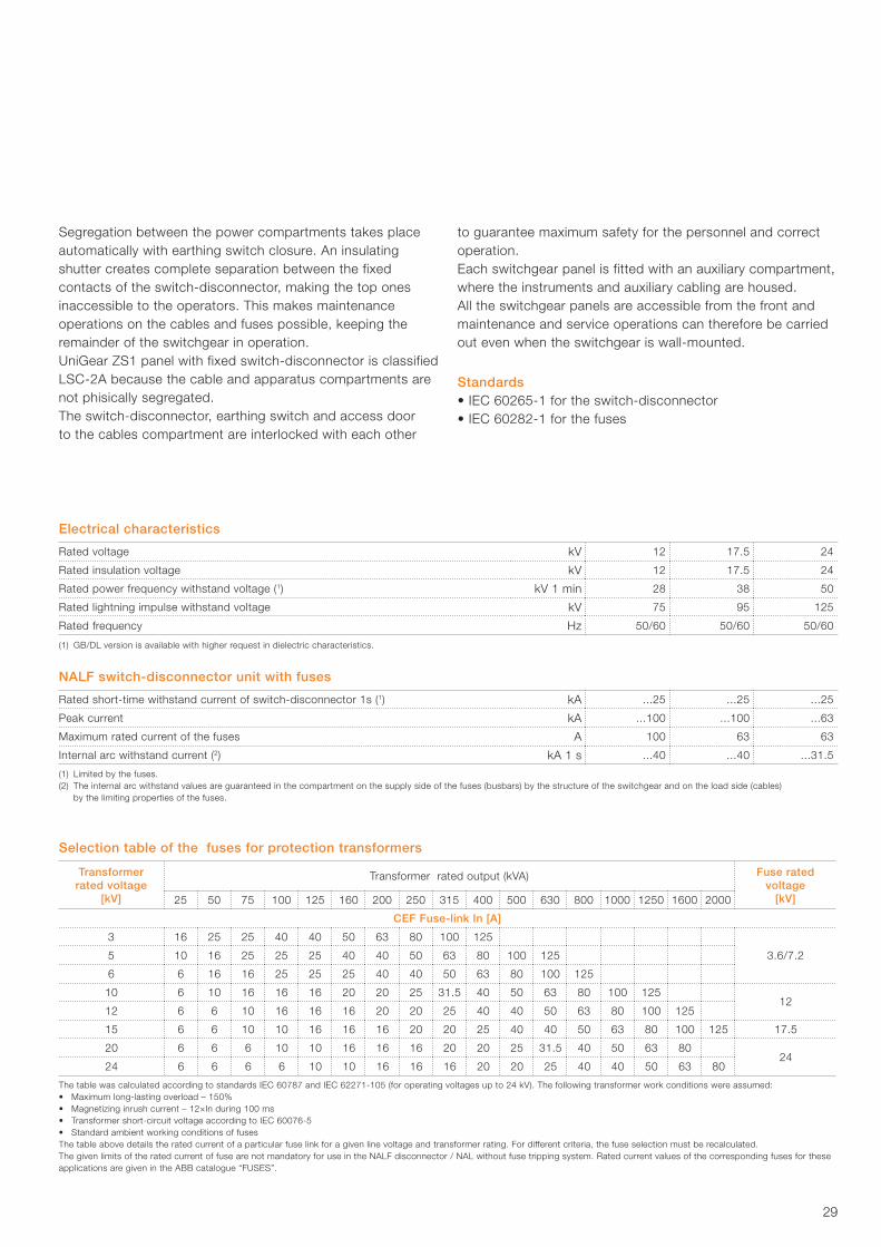
Selection table of the fuses for protection transformers
Transformer rated voltage
[kV]
Transformer rated output (kVA) Fuse rated voltage
[kV]25 50 75 100 125 160 200 250 315 400 500 630 800 1000 1250 1600 2000
CEF Fuse-link In [A]
3 16 25 25 40 40 50 63 80 100 125
3.6/7.25 10 16 25 25 25 40 40 50 63 80 100 125
6 6 16 16 25 25 25 40 40 50 63 80 100 125
10 6 10 16 16 16 20 20 25 31.5 40 50 63 80 100 12512
12 6 6 10 16 16 16 20 20 25 40 40 50 63 80 100 125
15 6 6 10 10 16 16 16 20 20 25 40 40 50 63 80 100 125 17.5
20 6 6 6 10 10 16 16 16 20 20 25 31.5 40 50 63 8024
24 6 6 6 6 10 10 16 16 16 20 20 25 40 40 50 63 80
The table was calculated according to standards IEC 60787 and IEC 62271-105 (for operating voltages up to 24 kV). The following transformer work conditions were assumed:• Maximum long-lasting overload – 150%• Magnetizing inrush current – 12×In during 100 ms• Transformer short-circuit voltage according to IEC 60076-5• Standard ambient working conditions of fusesThe table above details the rated current of a particular fuse link for a given line voltage and transformer rating. For different criteria, the fuse selection must be recalculated.The given limits of the rated current of fuse are not mandatory for use in the NALF disconnector / NAL without fuse tripping system. Rated current values of the corresponding fuses for these applications are given in the ABB catalogue “FUSES”.
(1) GB/DL version is available with higher request in dielectric characteristics.
30
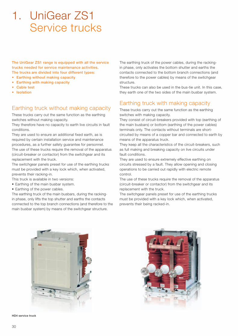
The UniGear ZS1 range is equipped with all the service trucks needed for service maintenance activities.The trucks are divided into four different types:• Earthing without making capacity• Earthing with making capacity• Cable test• Isolation
Earthing truck without making capacity These trucks carry out the same function as the earthing switches without making capacity.They therefore have no capacity to earth live circuits in fault conditions.They are used to ensure an additional fixed earth, as is required by certain installation service and maintenance procedures, as a further safety guarantee for personnel.The use of these trucks require the removal of the apparatus(circuit-breaker or contactor) from the switchgear and its replacement with the truck.The switchgear panels preset for use of the earthing trucks must be provided with a key lock which, when activated, prevents their racking-in.This truck is available in two versions:• Earthing of the main busbar system.• Earthing of the power cables. The earthing truck of the main busbars, during the racking-in phase, only lifts the top shutter and earths the contacts connected to the top branch connections (and therefore to the main busbar system) by means of the switchgear structure.
The earthing truck of the power cables, during the racking-in phase, only activates the bottom shutter and earths the contacts connected to the bottom branch connections (and therefore to the power cables) by means of the switchgearstructure.These trucks can also be used in the bus-tie unit. In this case, they earth one of the two sides of the main busbar system.
Earthing truck with making capacity These trucks carry out the same function as the earthing switches with making capacity.They consist of circuit-breakers provided with top (earthing of the main busbars) or bottom (earthing of the power cables) terminals only. The contacts without terminals are short-circuited by means of a copper bar and connected to earth bymeans of the apparatus truck.They keep all the characteristics of the circuit-breakers, such as full making and breaking capacity on live circuits under fault conditions.They are used to ensure extremely effective earthing on circuits stressed by a fault. They allow opening and closing operations to be carried out rapidly with electric remote control.The use of these trucks require the removal of the apparatus(circuit-breaker or contactor) from the switchgear and itsreplacement with the truck.The switchgear panels preset for use of the earthing trucks must be provided with a key lock which, when activated, prevents their being racked-in.
HD4 service truck
1. UniGear ZS1 Service trucks
31
This truck is available in two versions:• Earthing of the main busbar system.• Earthing of the power cables.The earthing truck of the main busbars, during the racking-in phase, only lifts the top shutter and presets the contacts connected to the top branch connections (and therefore to the main busbar system) for closing to earth by means of operating mechanism.
The earthing truck of the power cables, during the racking-in phase, only activates the bottom shutter and presets the contacts connected to the bottom branch connections (and therefore to the power cables) for closing to earth by means of operating mechanism.These trucks can also be used in the bus-tie unit. In this case, they earth one of the two sides of the main busbar system.
Power cable test truckThese trucks allow the insulation tests on the power cables to be carried out without accessing the feeder compartment or disconnecting the cables from the switchgear.The use of these trucks require the removal of the apparatus(circuit-breaker or contactor) from the switchgear and itsreplacement with the truck.
The truck, during the racking-in phase, only activates the bottom shutter and, by means of the connectors it is fitted with, allows connection of the test apparatus cables.This truck can only be used in the incoming/outgoing feeders with the door open.
Isolating truck The isolating truck allows the top switchgear contacts to be connected directly to the bottom ones. Connection is made extremely safe by using the poles of the circuit-breakers to insulate the connection busbars from the external environment. In the incoming/outgoing feeder units it connects the main busbar system to the power cables, whereas in the bus-tie, to the two sides of the busbar system.This truck has its application in UniGear switchgear for making incoming/outgoing feeders without a circuit-breaker in radial networks, for making cable connections between two items of switchgear placed in front of each other, in making interconnection units and in creating the bus-tie riser configuration with double insulation (in this case, both the units are made up of bus-ties, the former fitted with a circuit-breaker and the latter with an isolating truck).The switchgear panels preset for use of the isolating trucks must be fitted with a key lock which, when activated, prevents their being racked-in.
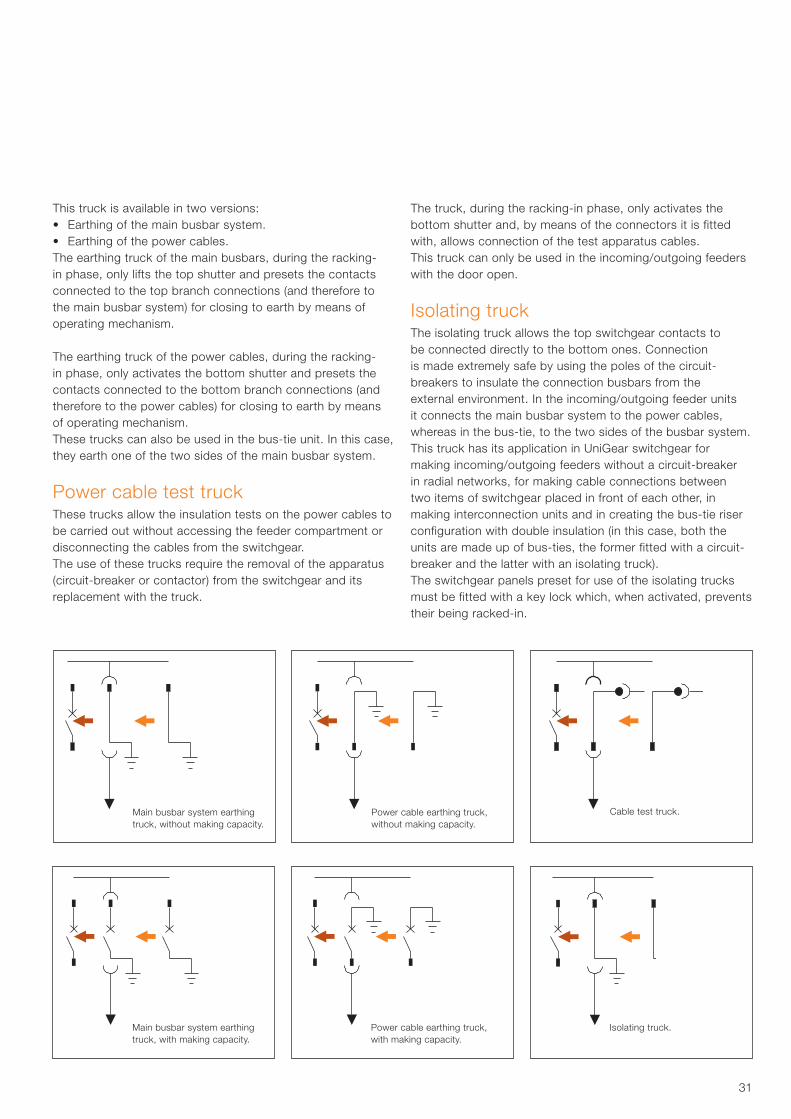
Main busbar system earthingtruck, without making capacity.
Power cable earthing truck,without making capacity.
Cable test truck.
Main busbar system earthingtruck, with making capacity.
Power cable earthing truck,with making capacity.
Isolating truck.

32
The Ultra-Fast Earthing Switch (UFES) is an innovative design of an active arc protection device which effectively mitigates the severe mechanical and thermal impacts caused by internal arc faults.
The UFES is a combination of devices consisting of an electronic unit and the corresponding primary switching elements which initiate a three-phase earthing in the event of an arc fault. With operating times of less than 4 ms after detection UFES clears an internal arc fault almost immediately after it arises. Thus arc impacts are reduced to an absolute minimum and safety standards raised to a whole new level.
UFES kit Primary switching element installed in the cable compartment
Electrical maximum characteristics in UniGear ZS1 IEC
Rated insulation voltage (rms) (1) kV 12 17.5 24
Rated power frequency withstand voltage (rms) kV 28 38 50
Rated lightning impulse withstand voltage (peak) kV 75 95 125
Rated frequency Hz 50/60 50/60 50/60
Rated short-time withstand current (rms) (1) kA 50 50 31.5
Rated short-circuit making current kA 125 125 80
Rated duration of short-circuit s 3 3 3
(1) GB/DL version is available with higher request in dielectric characteristics (42 kV) and short-time withstand current (4 s).
The UFES is available to fulfil a variety of applications in the UniGear ZS1 switchgear e.g.:• Busbar installation with top-housing box• Cable compartment installation
Unbeatable advantages in case of an arc fault event
• Drastic reduction of repair costs: no damages on the switchgear equipment to be expected. No exchange of the faulty panel.
• Greatly increased system availability: after inspection and elimination of the fault reason the switchgear can be taken into service again within shortest possible time.
• Greatly increased operator safety for human mal-operation under maintenance conditions
• Minimized secondary effects like light/sound emission or the release of toxic gases
• Solution for pressure sensitive environment with limited pressure relief options
1. UniGear ZS1 Ultra Fast Earthing Switch
33
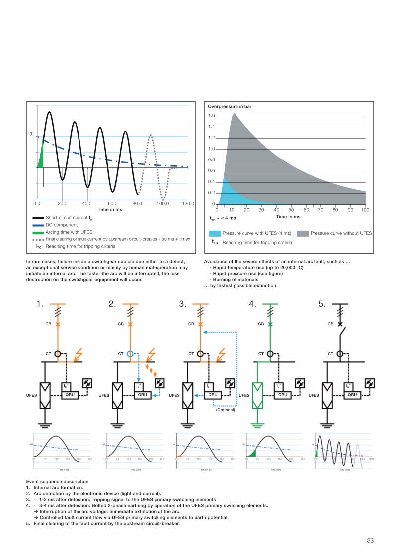
0.0 20.0 40.0 60.0 80.0 100.0 120.0
I(t)
Time in ms
Short-circuit current In
DC component
Arcing time with UFES
Final clearing of fault current by upstream circuit-breaker - 80 ms + timex
Reaching time for tripping criteria
0 10 20 30 40 50 60 70 80 90 100
1.6
1.4
1.2
1.0
0.8
0.6
0.4
0.2
0
Time in ms
Overpressure in bar
Pressure curve with UFES (4 ms) Pressure curve without UFES
Reaching time for tripping criteria
0.0 5.0 10.0 15.0 20.0 25.0
I(t)
Time in ms
0.0 5.0 10.0 15.0 20.0 25.0
I(t)
Time in ms
0.0 5.0 10.0 15.0 20.0 25.0
I(t)
Time in ms
0.0 5.0 10.0 15.0 20.0 25.0
I(t)
Time in ms
0.0 20.0 40.0 60.0 80.0 100.0 120.0
I(t)
Time in ms
UFES
CT
CB
1.
QRU
Ik“
UFES
CT
CB
2.
QRU
Ik“
UFES
CT
CB
3.
QRU
Ik“
UFES
CT
CB
4.
QRU
Ik“
UFES
CT
CB
5.
QRU
Ik“
(Optional)
tTC + < 4 ms
tTC
tTC
In rare cases, failure inside a switchgear cubicle due either to a defect, an exceptional service condition or mainly by human mal-operation may initiate an internal arc. The faster the arc will be interrupted, the less destruction on the switchgear equipment will occur.
Avoidance of the severe effects of an internal arc fault, such as … - Rapid temperature rise (up to 20,000 °C) - Rapid pressure rise (see figure) - Burning of materials… by fastest possible extinction.
Event sequence description1. Internal arc formation.2. Arc detection by the electronic device (light and current).3. ~ 1-2 ms after detection: Tripping signal to the UFES primary switching elements 4. ~ 3-4 ms after detection: Bolted 3-phase earthing by operation of the UFES primary switching elements. à Interruption of the arc voltage: Immediate extinction of the arc. à Controlled fault current flow via UFES primary switching elements to earth potential. 5. Final clearing of the fault current by the upstream circuit-breaker.
34
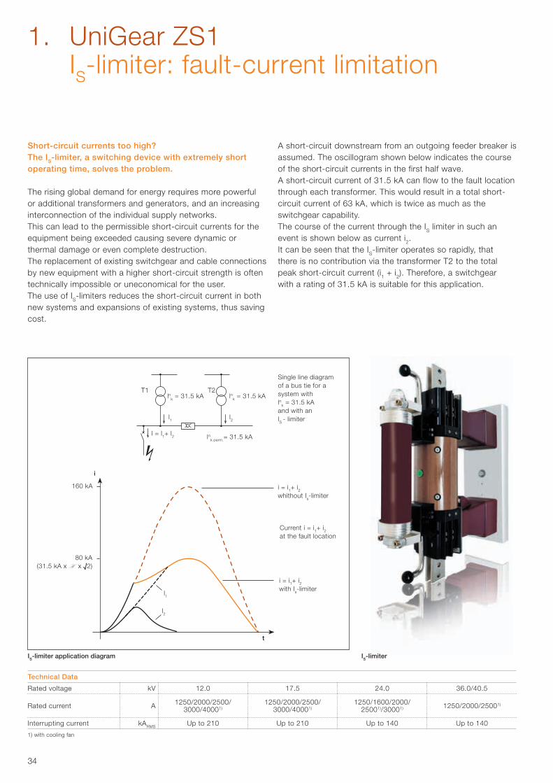
i
t
160 kA
80 kA(31.5 kA x H x √2)
lnk perm.= 31.5 kA
lnk = 31.5 kA lnk = 31.5 kA T1 T2
l = l1+ l2
l1 l2
l1
l2
Short-circuit currents too high?The IS-limiter, a switching device with extremely short operating time, solves the problem.
The rising global demand for energy requires more powerful or additional transformers and generators, and an increasing interconnection of the individual supply networks.This can lead to the permissible short-circuit currents for theequipment being exceeded causing severe dynamic or thermal damage or even complete destruction.The replacement of existing switchgear and cable connectionsby new equipment with a higher short-circuit strength is oftentechnically impossible or uneconomical for the user. The use of IS-limiters reduces the short-circuit current in both new systems and expansions of existing systems, thus saving cost.
A short-circuit downstream from an outgoing feeder breaker isassumed. The oscillogram shown below indicates the courseof the short-circuit currents in the first half wave.A short-circuit current of 31.5 kA can flow to the fault locationthrough each transformer. This would result in a total short-circuit current of 63 kA, which is twice as much as the switchgear capability.The course of the current through the IS limiter in such anevent is shown below as current i2.It can be seen that the IS-limiter operates so rapidly, thatthere is no contribution via the transformer T2 to the totalpeak short-circuit current (i1 + i2). Therefore, a switchgearwith a rating of 31.5 kA is suitable for this application.
i = i1+ i2whithout Is-limiter
Current i = i1+ i2at the fault location
i = i1+ i2with Is-limiter
Single line diagram of a bus tie for a system with lnk = 31.5 kA and with an lS - limiter
Technical Data
Rated voltage kV 12.0 17.5 24.0 36.0/40.5
Rated current A 1250/2000/2500/ 3000/40001)
1250/2000/2500/ 3000/40001)
1250/1600/2000/ 25001)/30001) 1250/2000/25001)
Interrupting current kARMS Up to 210 Up to 210 Up to 140 Up to 140
1) with cooling fan
1. UniGear ZS1 IS-limiter: fault-current limitation
IS-limiter application diagram IS-limiter
35
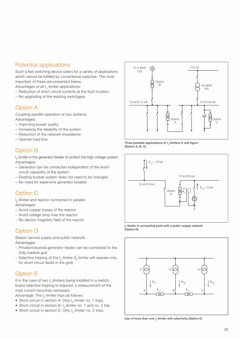
110 kV
40 MVA8%
10 kV/31.5 kA 10 kV/40 kA
Option A
Option C
Option B
10 kV/16 kA
10 kV/25 kA
IııkT = 15 kA
IııkG = 3 kA
T1
A B CIS-1
IT1
T2
IS-2
IT2
T3
IT3
Option D
31.5 MVA12%
Potential applications Such a fast switching device caters for a variety of applications which cannot be fulfilled by conventional switches. The most important of these are presented below.Advantages of all IS-limiter applications:– Reduction of short-circuit currents at the fault location– No upgrading of the existing switchgear.
Option A Coupling-parallel operation of two systems. Advantages:– Improving power quality– Increasing the reliability of the system– Reduction of the network-impedance– Optimal load flow
Option BIS-limiter in the generator feeder to protect the high voltage system. Advantages:– Generator can be connected independent of the short-
circuit capability of the system– Existing busbar system does not need to be changed– No need for expensive generator breaker
Option CIS-limiter and reactor connected in parallel.Advantages:– Avoid copper losses of the reactor– Avoid voltage drop over the reactor– No electro-magnetic field of the reactor
Option D Station service supply and public network. Advantages:– Private/industrial generator feeder can be connected to the
(fully loaded) grid– Selective tripping of the IS-limiter (IS-limiter will operate only
for short-circuit faults in the grid)
Option EIf in the case of two IS-limiters being installed in a switch-board selective tripping is required, a measurement of the total current becomes necessary.Advantage: The IS-limiter trips as follows:• Short-circuit in section A: Only IS-limiter no. 1 trips.• Short-circuit in section B: IS-limiter no. 1 and no. 2 trip.• Short-circuit in section C: Only IS-limiter no. 2 trips.
Three possible applications of IS-limiters in one figure (Option A, B, C)
Use of more than one Is-limiter with selectivity (Option E)
Is-limiter in connecting point with a public supply network (Option D)
36
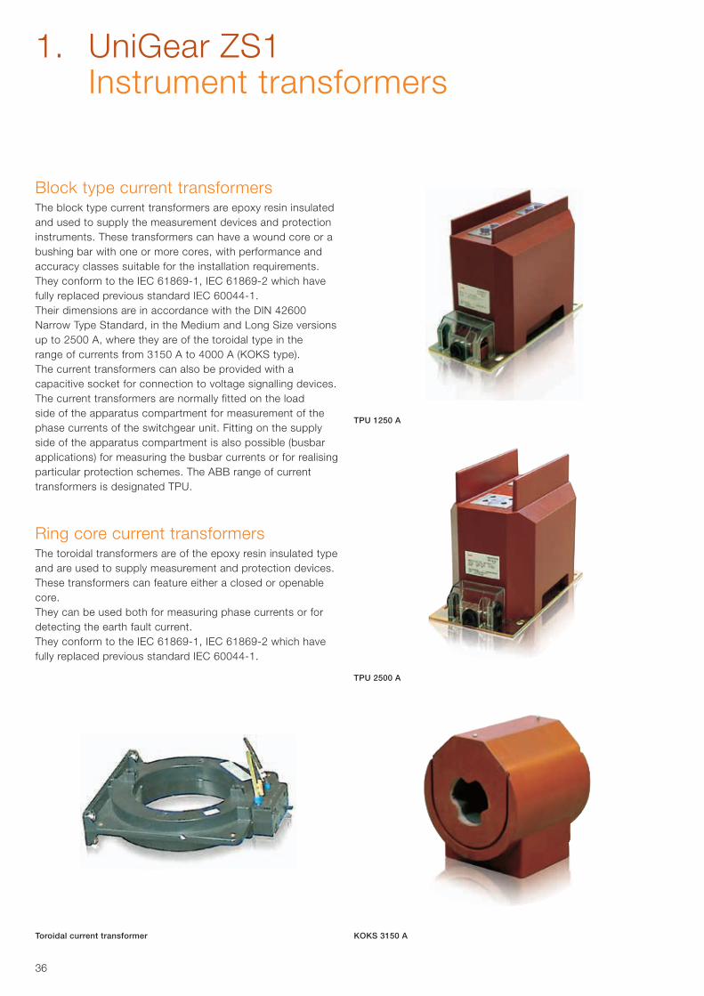
Block type current transformersThe block type current transformers are epoxy resin insulated and used to supply the measurement devices and protectioninstruments. These transformers can have a wound core or abushing bar with one or more cores, with performance andaccuracy classes suitable for the installation requirements.They conform to the IEC 61869-1, IEC 61869-2 which have fully replaced previous standard IEC 60044-1.Their dimensions are in accordance with the DIN 42600Narrow Type Standard, in the Medium and Long Size versionsup to 2500 A, where they are of the toroidal type in therange of currents from 3150 A to 4000 A (KOKS type).The current transformers can also be provided with acapacitive socket for connection to voltage signalling devices.The current transformers are normally fitted on the loadside of the apparatus compartment for measurement of thephase currents of the switchgear unit. Fitting on the supplyside of the apparatus compartment is also possible (busbarapplications) for measuring the busbar currents or for realisingparticular protection schemes. The ABB range of currenttransformers is designated TPU.
Ring core current transformersThe toroidal transformers are of the epoxy resin insulated type and are used to supply measurement and protection devices.These transformers can feature either a closed or openablecore.They can be used both for measuring phase currents or fordetecting the earth fault current.They conform to the IEC 61869-1, IEC 61869-2 which have fully replaced previous standard IEC 60044-1.
TPU 1250 A
TPU 2500 A
Toroidal current transformer KOKS 3150 A
1. UniGear ZS1 Instrument transformers
37
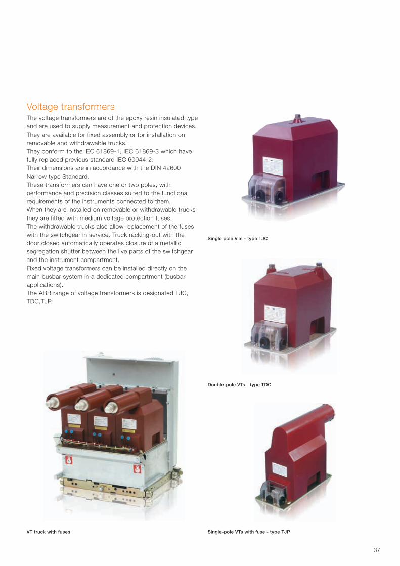
Voltage transformersThe voltage transformers are of the epoxy resin insulated typeand are used to supply measurement and protection devices.They are available for fixed assembly or for installation onremovable and withdrawable trucks.They conform to the IEC 61869-1, IEC 61869-3 which have fully replaced previous standard IEC 60044-2.Their dimensions are in accordance with the DIN 42600Narrow type Standard.These transformers can have one or two poles, withperformance and precision classes suited to the functionalrequirements of the instruments connected to them.When they are installed on removable or withdrawable trucksthey are fitted with medium voltage protection fuses.The withdrawable trucks also allow replacement of the fuseswith the switchgear in service. Truck racking-out with thedoor closed automatically operates closure of a metallicsegregation shutter between the live parts of the switchgearand the instrument compartment.Fixed voltage transformers can be installed directly on themain busbar system in a dedicated compartment (busbarapplications).The ABB range of voltage transformers is designated TJC,TDC,TJP.
VT truck with fuses
Single pole VTs - type TJC
Double-pole VTs - type TDC
Single-pole VTs with fuse - type TJP
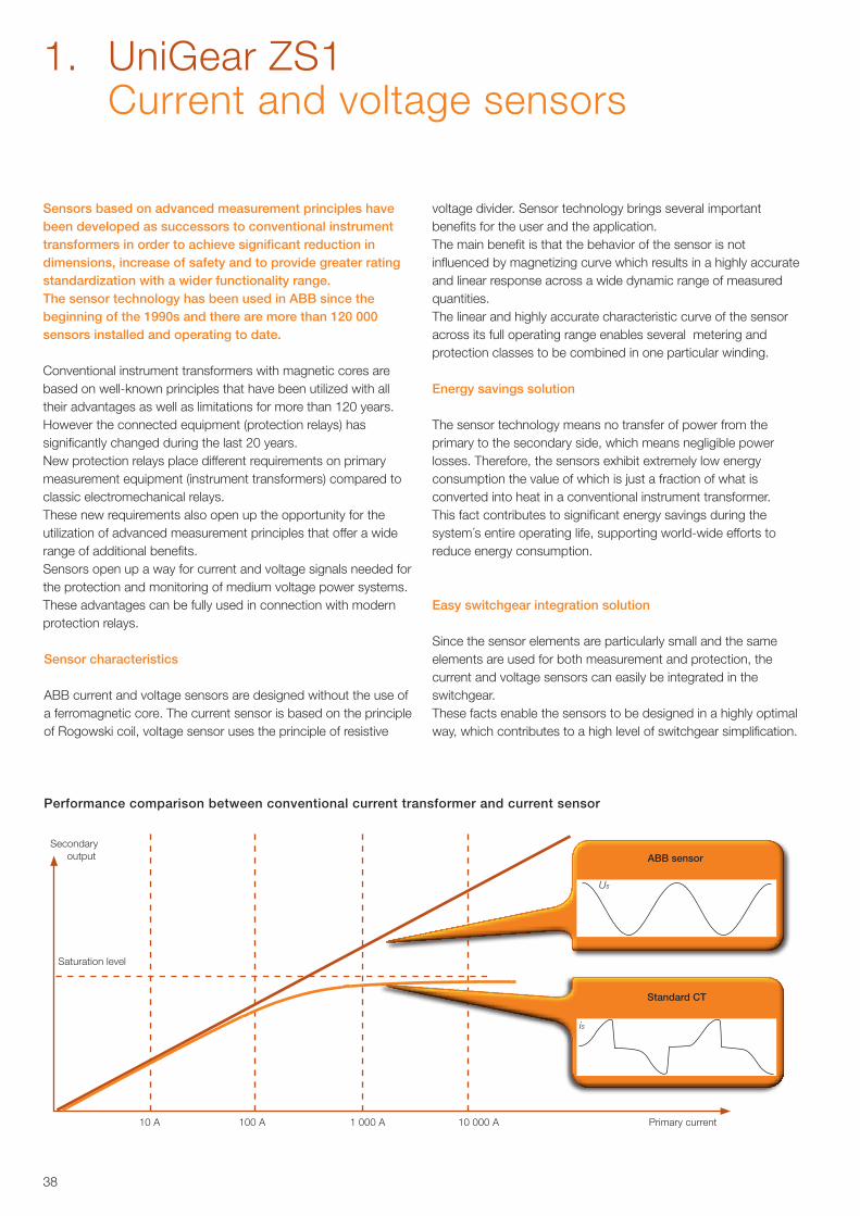
38
1. UniGear ZS1 Current and voltage sensors
Sensors based on advanced measurement principles have been developed as successors to conventional instrument transformers in order to achieve significant reduction in dimensions, increase of safety and to provide greater rating standardization with a wider functionality range. The sensor technology has been used in ABB since the beginning of the 1990s and there are more than 120 000 sensors installed and operating to date.
Conventional instrument transformers with magnetic cores are based on well-known principles that have been utilized with all their advantages as well as limitations for more than 120 years. However the connected equipment (protection relays) has significantly changed during the last 20 years. New protection relays place different requirements on primary measurement equipment (instrument transformers) compared to classic electromechanical relays. These new requirements also open up the opportunity for the utilization of advanced measurement principles that offer a wide range of additional benefits.Sensors open up a way for current and voltage signals needed for the protection and monitoring of medium voltage power systems. These advantages can be fully used in connection with modern protection relays.
Sensor characteristics
ABB current and voltage sensors are designed without the use of a ferromagnetic core. The current sensor is based on the principle of Rogowski coil, voltage sensor uses the principle of resistive
Energy savings solution
The sensor technology means no transfer of power from the primary to the secondary side, which means negligible power losses. Therefore, the sensors exhibit extremely low energy consumption the value of which is just a fraction of what is converted into heat in a conventional instrument transformer. This fact contributes to significant energy savings during the system´s entire operating life, supporting world-wide efforts to reduce energy consumption.
Easy switchgear integration solution
Since the sensor elements are particularly small and the same elements are used for both measurement and protection, the current and voltage sensors can easily be integrated in the switchgear. These facts enable the sensors to be designed in a highly optimal way, which contributes to a high level of switchgear simplification.
Performance comparison between conventional current transformer and current sensor
is
Us
Secondaryoutput
Saturation level
10 A 100 A 1 000 A 10 000 A Primary current
ABB sensor
Standard CT
voltage divider. Sensor technology brings several important benefits for the user and the application.The main benefit is that the behavior of the sensor is not influenced by magnetizing curve which results in a highly accurate and linear response across a wide dynamic range of measured quantities. The linear and highly accurate characteristic curve of the sensor across its full operating range enables several metering and protection classes to be combined in one particular winding.
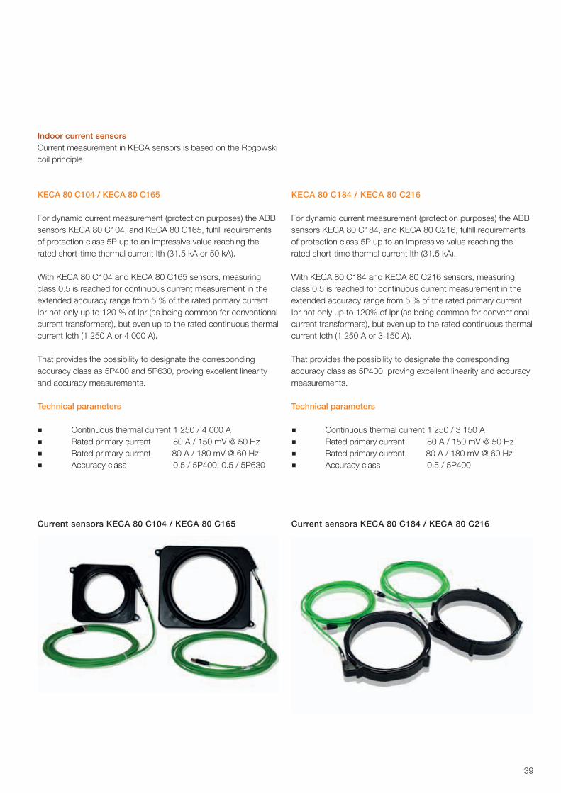
39
Current sensors KECA 80 C104 / KECA 80 C165
Indoor current sensorsCurrent measurement in KECA sensors is based on the Rogowski coil principle.
KECA 80 C104 / KECA 80 C165
For dynamic current measurement (protection purposes) the ABB sensors KECA 80 C104, and KECA 80 C165, fulfill requirements of protection class 5P up to an impressive value reaching the rated short-time thermal current Ith (31.5 kA or 50 kA).
With KECA 80 C104 and KECA 80 C165 sensors, measuring class 0.5 is reached for continuous current measurement in the extended accuracy range from 5 % of the rated primary current Ipr not only up to 120 % of Ipr (as being common for conventional current transformers), but even up to the rated continuous thermal current Icth (1 250 A or 4 000 A).
That provides the possibility to designate the corresponding accuracy class as 5P400 and 5P630, proving excellent linearity and accuracy measurements.
Technical parameters
■ Continuous thermal current 1 250 / 4 000 A■ Rated primary current 80 A / 150 mV @ 50 Hz■ Rated primary current 80 A / 180 mV @ 60 Hz■ Accuracy class 0.5 / 5P400; 0.5 / 5P630
KECA 80 C184 / KECA 80 C216
For dynamic current measurement (protection purposes) the ABB sensors KECA 80 C184, and KECA 80 C216, fulfill requirements of protection class 5P up to an impressive value reaching the rated short-time thermal current Ith (31.5 kA).
With KECA 80 C184 and KECA 80 C216 sensors, measuring class 0.5 is reached for continuous current measurement in the extended accuracy range from 5 % of the rated primary current Ipr not only up to 120% of Ipr (as being common for conventional current transformers), but even up to the rated continuous thermal current Icth (1 250 A or 3 150 A).
That provides the possibility to designate the corresponding accuracy class as 5P400, proving excellent linearity and accuracy measurements.
Technical parameters
■ Continuous thermal current 1 250 / 3 150 A■ Rated primary current 80 A / 150 mV @ 50 Hz■ Rated primary current 80 A / 180 mV @ 60 Hz■ Accuracy class 0.5 / 5P400
Current sensors KECA 80 C184 / KECA 80 C216
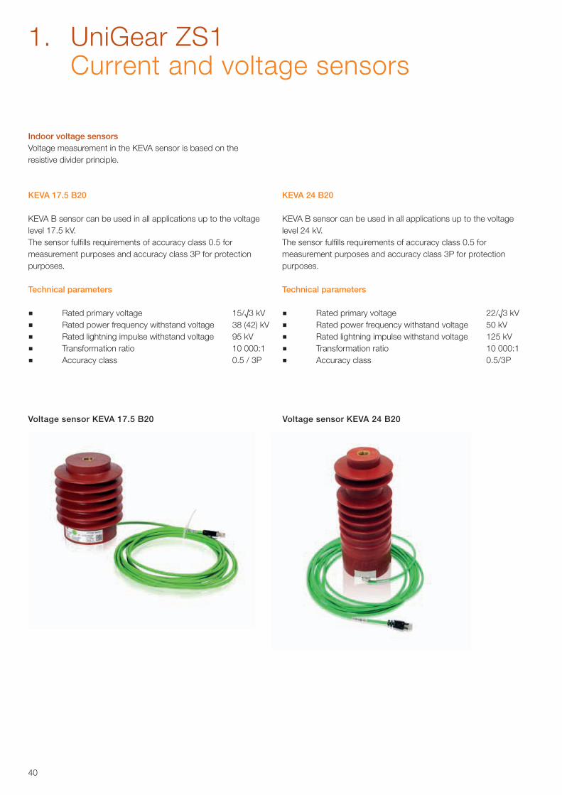
40
1. UniGear ZS1 Current and voltage sensors
Voltage sensor KEVA 17.5 B20
Indoor voltage sensorsVoltage measurement in the KEVA sensor is based on the resistive divider principle.
KEVA 17.5 B20
KEVA B sensor can be used in all applications up to the voltage level 17.5 kV.The sensor fulfills requirements of accuracy class 0.5 for measurement purposes and accuracy class 3P for protection purposes.
Technical parameters
■ Rated primary voltage 15/√3 kV ■ Rated power frequency withstand voltage 38 (42) kV■ Rated lightning impulse withstand voltage 95 kV■ Transformation ratio 10 000:1■ Accuracy class 0.5 / 3P
Voltage sensor KEVA 24 B20
KEVA 24 B20
KEVA B sensor can be used in all applications up to the voltage level 24 kV.The sensor fulfills requirements of accuracy class 0.5 for measurement purposes and accuracy class 3P for protection purposes.
Technical parameters
■ Rated primary voltage 22/√3 kV ■ Rated power frequency withstand voltage 50 kV■ Rated lightning impulse withstand voltage 125 kV■ Transformation ratio 10 000:1■ Accuracy class 0.5/3P
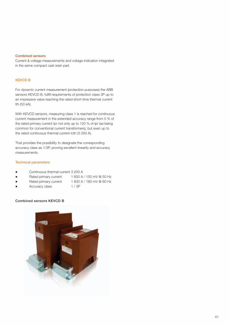
41
Combined sensorsCurrent & voltage measurements and voltage indication integrated in the same compact cast resin part.
KEVCD B
For dynamic current measurement (protection purposes) the ABBsensors KEVCD B, fulfill requirements of protection class 3P up toan impressive value reaching the rated short-time thermal currentIth (50 kA).
With KEVCD sensors, measuring class 1 is reached for continuouscurrent measurement in the extended accuracy range from 5 % ofthe rated primary current Ipr not only up to 120 % of Ipr (as beingcommon for conventional current transformers), but even up tothe rated continuous thermal current Icth (3 200 A).
That provides the possibility to designate the correspondingaccuracy class as 1/3P, proving excellent linearity and accuracymeasurements.
Technical parameters
■ Continuous thermal current 3 200 A ■ Rated primary current 1 600 A / 150 mV @ 50 Hz■ Rated primary current 1 600 A / 180 mV @ 60 Hz■ Accuracy class 1 / 3P
Combined sensors KEVCD B
42
1. UniGear ZS1 Cable terminations
Terminations for polymer insulated cables 1 – 24 kVIt is crucial that power cables connecting the switchgear are terminated properly, and for this purpose, ABB has developed an excellent range of easy-to-use products for preparation and termination of cables.MV power cables are normally designed with a conductor of aluminium or copper, an insulation of polymer material, an extruded insulation screen, a metallic screen, armouring (optional) and a polymeric outer jacket.To enable safe and reliable current carrying properties, it is necessary to achieve sufficient mechanical connection between the cable conductor and the bus bar. ABB offers mechanical cable lugs designed to fit the cable conductor by bolting. It is also essential to guide the electrical field of the cable correctly, and ABB offers Cold Applied terminations, made of rubber, that create an active pressure around the cable. Furthermore, if the cable is designed with another type of metallic screen than copper wires, special earthing kits must be used to achieve proper handling of possible fault currents. The armouring of the cable must have the same earth potential as the cable screen, so it might be necessary to use additional connection accessories that are also available. Detailed information can be found in separate technical information for cable accessories.
Applications and featuresDepending on the cable design, it is necessary to use the correct type of cable accessory. When single core cables are designed with copper wire screen only, it is sufficient to use just a cable lug and a termination that fits the actual size of the cable.The benefit of Cold Applied accessories is that no heat or open flame is necessary for installation (except for branch seals on 3-core cables). After the cable is prepared, the termination is simply slid on without any tools. If a three core cable is used, or a cable with copper tape screen, or aluminium foil screen, or a cable with armouring; then additional material is required.Another very important factor is correct cable preparation, and ABB also offers excellent cable preparation tools.
Recommended cable termination productsThe pre-moulded cable termination type Kabeldon SOT can be used on any polymer cable irrespective of design or conductor size. Type SOT 10 is designed for 7.2 kV cables, while type SOT 24 covers 12, 17.5 and 24 kV. A few variants of terminations fit a wide range of cable sizes. Extra material such as earthing kits, crutch seals for 3-core cables and screen potential material for cable armouring is also covered by the ABB range of products. Please contact your ABB SalesRepresentative for more information.
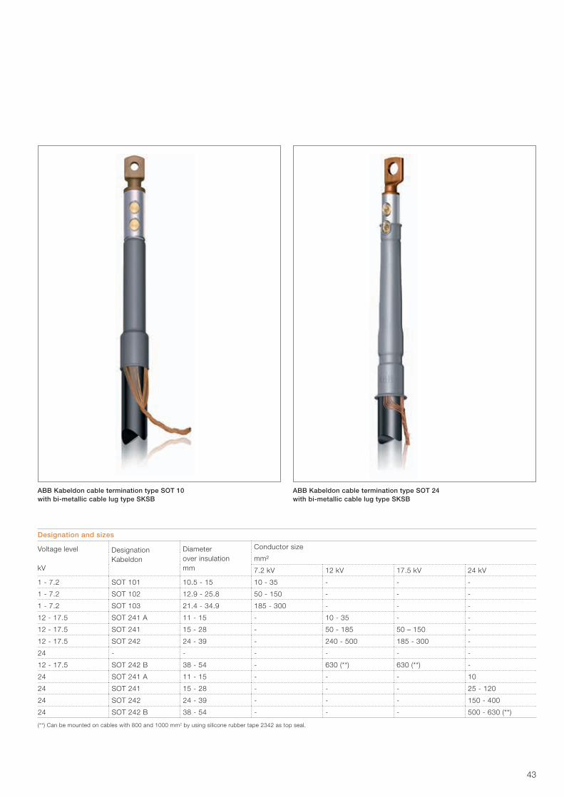
43
ABB Kabeldon cable termination type SOT 10 with bi-metallic cable lug type SKSB
ABB Kabeldon cable termination type SOT 24 with bi-metallic cable lug type SKSB
Designation and sizes
Voltage level
kV
Designation Kabeldon
Diameter over insulationmm
Conductor size
mm²
7.2 kV 12 kV 17.5 kV 24 kV
1 - 7.2 SOT 101 10.5 - 15 10 - 35 - - -
1 - 7.2 SOT 102 12.9 - 25.8 50 - 150 - - -
1 - 7.2 SOT 103 21.4 - 34.9 185 - 300 - - -
12 - 17.5 SOT 241 A 11 - 15 - 10 - 35 - -
12 - 17.5 SOT 241 15 - 28 - 50 - 185 50 – 150 -
12 - 17.5 SOT 242 24 - 39 - 240 - 500 185 - 300 -
24 - - - - - -
12 - 17.5 SOT 242 B 38 - 54 - 630 (**) 630 (**) -
24 SOT 241 A 11 - 15 - - - 10
24 SOT 241 15 - 28 - - - 25 - 120
24 SOT 242 24 - 39 - - - 150 - 400
24 SOT 242 B 38 - 54 - - - 500 - 630 (**)
(**) Can be mounted on cables with 800 and 1000 mm2 by using silicone rubber tape 2342 as top seal.
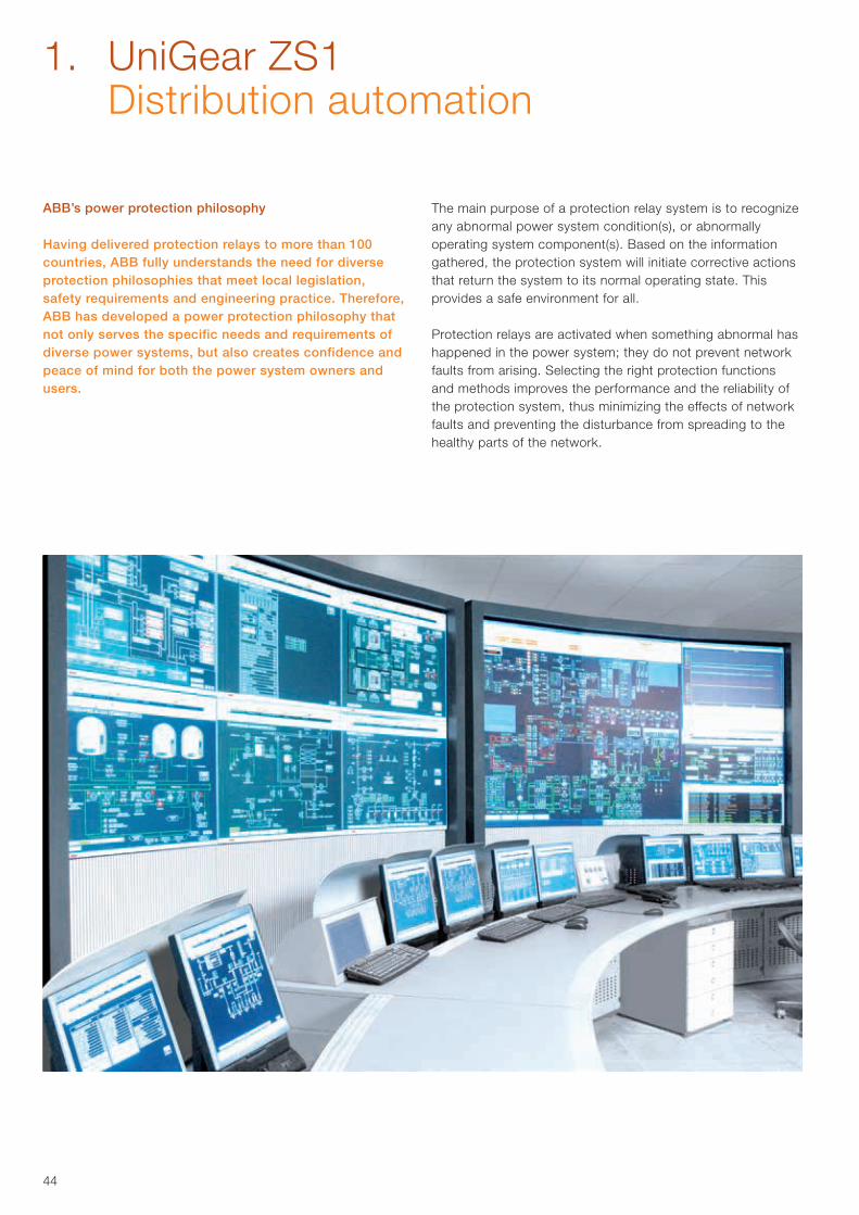
44
ABB’s power protection philosophy
Having delivered protection relays to more than 100 countries, ABB fully understands the need for diverse protection philosophies that meet local legislation, safety requirements and engineering practice. Therefore, ABB has developed a power protection philosophy that not only serves the specific needs and requirements of diverse power systems, but also creates confidence and peace of mind for both the power system owners and users.
The main purpose of a protection relay system is to recognize any abnormal power system condition(s), or abnormally operating system component(s). Based on the information gathered, the protection system will initiate corrective actions that return the system to its normal operating state. This provides a safe environment for all.
Protection relays are activated when something abnormal has happened in the power system; they do not prevent network faults from arising. Selecting the right protection functions and methods improves the performance and the reliability of the protection system, thus minimizing the effects of network faults and preventing the disturbance from spreading to the healthy parts of the network.
1. UniGear ZS1 Distribution automation
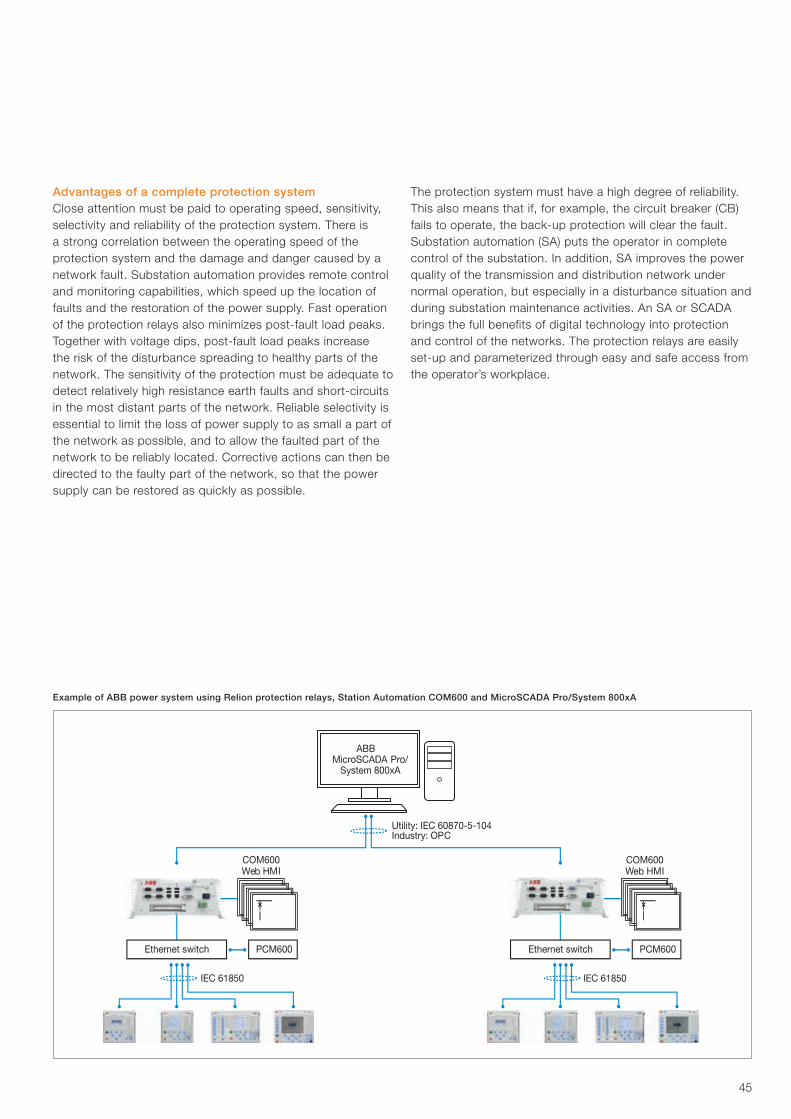
45
PCM600Ethernet switch
Utility: IEC 60870-5-104Industry: OPC
COM600Web HMI
IEC 61850
PCM600Ethernet switch
COM600Web HMI
IEC 61850
ABBMicroSCADA Pro/
System 800xA
Example of ABB power system using Relion protection relays, Station Automation COM600 and MicroSCADA Pro/System 800xA
The protection system must have a high degree of reliability. This also means that if, for example, the circuit breaker (CB) fails to operate, the back-up protection will clear the fault. Substation automation (SA) puts the operator in complete control of the substation. In addition, SA improves the power quality of the transmission and distribution network under normal operation, but especially in a disturbance situation and during substation maintenance activities. An SA or SCADA brings the full benefits of digital technology into protection and control of the networks. The protection relays are easily set-up and parameterized through easy and safe access from the operator’s workplace.
Advantages of a complete protection systemClose attention must be paid to operating speed, sensitivity, selectivity and reliability of the protection system. There is a strong correlation between the operating speed of the protection system and the damage and danger caused by a network fault. Substation automation provides remote control and monitoring capabilities, which speed up the location of faults and the restoration of the power supply. Fast operation of the protection relays also minimizes post-fault load peaks. Together with voltage dips, post-fault load peaks increase the risk of the disturbance spreading to healthy parts of the network. The sensitivity of the protection must be adequate to detect relatively high resistance earth faults and short-circuits in the most distant parts of the network. Reliable selectivity is essential to limit the loss of power supply to as small a part of the network as possible, and to allow the faulted part of the network to be reliably located. Corrective actions can then be directed to the faulty part of the network, so that the power supply can be restored as quickly as possible.
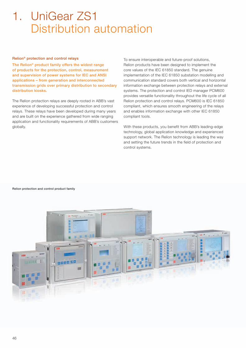
46
Relion® protection and control relays
The Relion® product family offers the widest range of products for the protection, control, measurement and supervision of power systems for IEC and ANSI applications – from generation and interconnected transmission grids over primary distribution to secondary distribution kiosks.
The Relion protection relays are deeply rooted in ABB’s vast experience of developing successful protection and control relays. These relays have been developed during many years and are built on the experience gathered from wide ranging application and functionality requirements of ABB’s customers globally.
To ensure interoperable and future-proof solutions, Relion products have been designed to implement the core values of the IEC 61850 standard. The genuine implementation of the IEC 61850 substation modelling and communication standard covers both vertical and horizontal information exchange between protection relays and external systems. The protection and control IED manager PCM600 provides versatile functionality throughout the life cycle of all Relion protection and control relays. PCM600 is IEC 61850 compliant, which ensures smooth engineering of the relays and enables information exchange with other IEC 61850 compliant tools.
With these products, you benefit from ABB’s leading-edge technology, global application knowledge and experienced support network. The Relion technology is leading the way and setting the future trends in the field of protection and control systems.
Relion protection and control product family
1. UniGear ZS1 Distribution automation
47
Relion 605 seriesThe Relion 605 series protection relays feature basic devices that fulfill the essential protection needs in medium-voltage networks. The series is best suited for secondary distribution applications. These relays are well-known for their straight forward approach to protection.
Relion 610 seriesThe Relion 610 series provides dedicated protection for utility distribution and industrial applications. The 610 series protection relays offer protection and supervision of the medium-voltage power systems in a compact design. The 610 series is popular for its easy parametrization, thus short time-to-operation.
Relion 611 seriesThe Relion 611 series protection relays are powerful and very easy-to-use protection devices in a compact design. The 611 series relays are delivered with a pre-configured application, which can be adapted, to a limited extent, to application-specific needs. The series offers pre-configured solutions, which are ideally suited for utility distribution and industrial applications.
Relion 615 seriesThe Relion 615 series protection relays can be defined as a compact and versatile solution for power distribution in utility and industrial applications. The 615 series provides standard configurations, which allows you to easily adapt and set-up your applications, still allowing you to adapt the configuration according to application-specific needs. The 615 series combines compactness and powerful features in one smart package.
Relion 620 seriesThe Relion 620 series protection relays increase flexibility in demanding utility and industrial applications for power distribution. They are delivered with example configurations to ease adaptation into your specific applications. The series offers customization possibilities, which supports higher levels of standardization in the applications. The 620 series extends the hardware possibilities further compared to the 615 series.
Relion 630 seriesThe pre-configured Relion 630 series protection relays feature flexible and scalable functionality to adapt to different needs in power distribution networks and industrial applications. The 630 series protection relays contain pre-configured ap-plication configurations, which can be freely tailored to meet specific requirements for distribution applications.
Relion 650 seriesThe Relion 650 series offers ease of use from ready-to-use solutions. The 650 series protection relays provide optimum ‘off-the-shelf’ solutions. These relays are equipped and configured with complete protection functionality and default parameters to meet the needs of a wide range of applications within generation, transmission and sub-transmission.
Relion 670 seriesThe Relion 670 series protection and control relays provide versatile functionality, as well as maximum flexibility and performance to meet the highest requirements of any application in generation, transmission and sub-transmission protection systems. The 670 series relays are available as pre-configured and fully customized relays.
Relion Interactive Selection GuideThe Relion Interactive Selection Guide (ISG) helps you select the protection relay type that is the most suitable for your application. It also provides links to relevant documentation online. The Relion ISG is available at: http://abb.relionisg.com
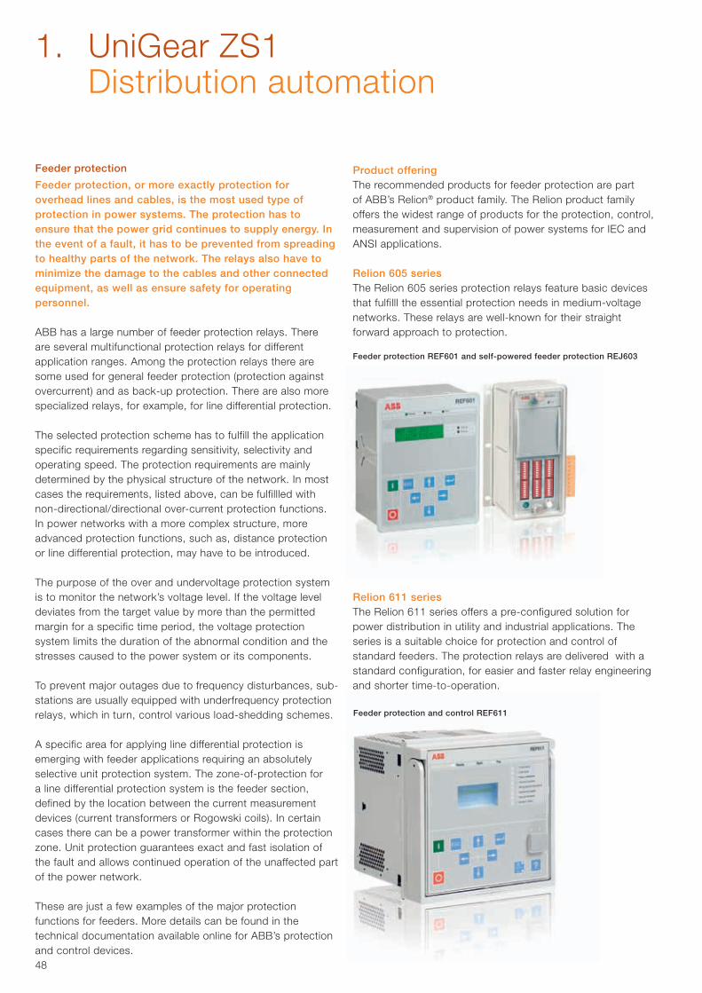
48
Feeder protection
Feeder protection, or more exactly protection for overhead lines and cables, is the most used type of protection in power systems. The protection has to ensure that the power grid continues to supply energy. In the event of a fault, it has to be prevented from spreading to healthy parts of the network. The relays also have to minimize the damage to the cables and other connected equipment, as well as ensure safety for operating personnel.
ABB has a large number of feeder protection relays. There are several multifunctional protection relays for different application ranges. Among the protection relays there are some used for general feeder protection (protection against overcurrent) and as back-up protection. There are also more specialized relays, for example, for line differential protection.
The selected protection scheme has to fulfill the application specific requirements regarding sensitivity, selectivity and operating speed. The protection requirements are mainly determined by the physical structure of the network. In most cases the requirements, listed above, can be fulfillled with non-directional/directional over-current protection functions.In power networks with a more complex structure, more advanced protection functions, such as, distance protection or line differential protection, may have to be introduced.
The purpose of the over and undervoltage protection system is to monitor the network’s voltage level. If the voltage level deviates from the target value by more than the permitted margin for a specific time period, the voltage protection system limits the duration of the abnormal condition and the stresses caused to the power system or its components.
To prevent major outages due to frequency disturbances, sub-stations are usually equipped with underfrequency protection relays, which in turn, control various load-shedding schemes.
A specific area for applying line differential protection is emerging with feeder applications requiring an absolutely selective unit protection system. The zone-of-protection for a line differential protection system is the feeder section, defined by the location between the current measurement devices (current transformers or Rogowski coils). In certain cases there can be a power transformer within the protection zone. Unit protection guarantees exact and fast isolation of the fault and allows continued operation of the unaffected part of the power network.
These are just a few examples of the major protection functions for feeders. More details can be found in the technical documentation available online for ABB’s protection and control devices.
Feeder protection REF601 and self-powered feeder protection REJ603
Feeder protection and control REF611
Product offeringThe recommended products for feeder protection are part of ABB’s Relion® product family. The Relion product family offers the widest range of products for the protection, control, measurement and supervision of power systems for IEC and ANSI applications.
Relion 605 seriesThe Relion 605 series protection relays feature basic devices that fulfilll the essential protection needs in medium-voltage networks. These relays are well-known for their straight forward approach to protection.
Relion 611 seriesThe Relion 611 series offers a pre-configured solution for power distribution in utility and industrial applications. The series is a suitable choice for protection and control of standard feeders. The protection relays are delivered with a standard configuration, for easier and faster relay engineering and shorter time-to-operation.
1. UniGear ZS1 Distribution automation
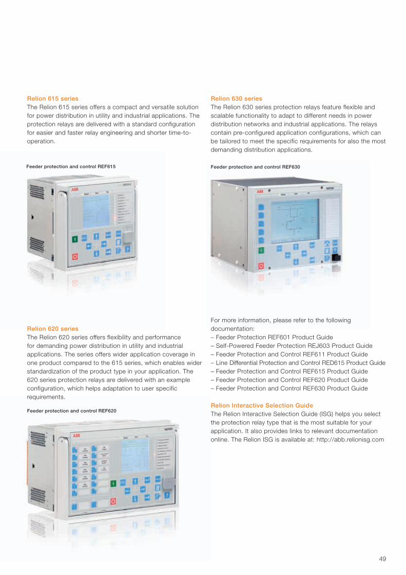
49
Relion 615 seriesThe Relion 615 series offers a compact and versatile solution for power distribution in utility and industrial applications. The protection relays are delivered with a standard configuration for easier and faster relay engineering and shorter time-to-operation.
Feeder protection and control REF615
Feeder protection and control REF620
Feeder protection and control REF630
Relion 630 seriesThe Relion 630 series protection relays feature flexible and scalable functionality to adapt to different needs in power distribution networks and industrial applications. The relays contain pre-configured application configurations, which can be tailored to meet the specific requirements for also the most demanding distribution applications.
For more information, please refer to the following documentation:– Feeder Protection REF601 Product Guide– Self-Powered Feeder Protection REJ603 Product Guide– Feeder Protection and Control REF611 Product Guide– Line Differential Protection and Control RED615 Product Guide– Feeder Protection and Control REF615 Product Guide– Feeder Protection and Control REF620 Product Guide– Feeder Protection and Control REF630 Product Guide
Relion Interactive Selection GuideThe Relion Interactive Selection Guide (ISG) helps you select the protection relay type that is the most suitable for your application. It also provides links to relevant documentation online. The Relion ISG is available at: http://abb.relionisg.com
Relion 620 seriesThe Relion 620 series offers flexibility and performance for demanding power distribution in utility and industrial applications. The series offers wider application coverage in one product compared to the 615 series, which enables wider standardization of the product type in your application. The 620 series protection relays are delivered with an example configuration, which helps adaptation to user specific requirements.
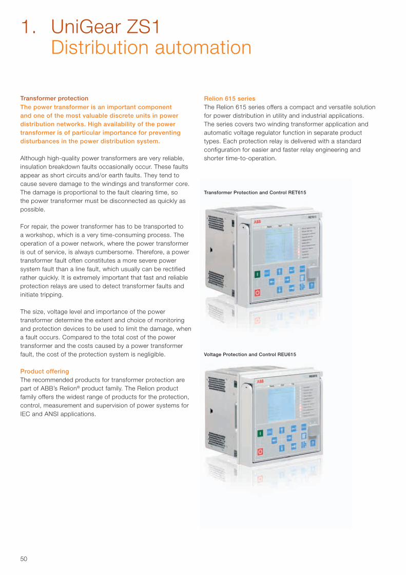
50
Transformer protectionThe power transformer is an important component and one of the most valuable discrete units in power distribution networks. High availability of the power transformer is of particular importance for preventing disturbances in the power distribution system.
Although high-quality power transformers are very reliable, insulation breakdown faults occasionally occur. These faults appear as short circuits and/or earth faults. They tend to cause severe damage to the windings and transformer core. The damage is proportional to the fault clearing time, so the power transformer must be disconnected as quickly as possible.
For repair, the power transformer has to be transported to a workshop, which is a very time-consuming process. The operation of a power network, where the power transformer is out of service, is always cumbersome. Therefore, a power transformer fault often constitutes a more severe power system fault than a line fault, which usually can be rectified rather quickly. It is extremely important that fast and reliable protection relays are used to detect transformer faults and initiate tripping.
The size, voltage level and importance of the power transformer determine the extent and choice of monitoring and protection devices to be used to limit the damage, when a fault occurs. Compared to the total cost of the power transformer and the costs caused by a power transformer fault, the cost of the protection system is negligible.
Product offeringThe recommended products for transformer protection are part of ABB’s Relion® product family. The Relion product family offers the widest range of products for the protection, control, measurement and supervision of power systems for IEC and ANSI applications.
Relion 615 seriesThe Relion 615 series offers a compact and versatile solution for power distribution in utility and industrial applications. The series covers two winding transformer application and automatic voltage regulator function in separate product types. Each protection relay is delivered with a standard configuration for easier and faster relay engineering and shorter time-to-operation.
Transformer Protection and Control RET615
Voltage Protection and Control REU615
1. UniGear ZS1 Distribution automation
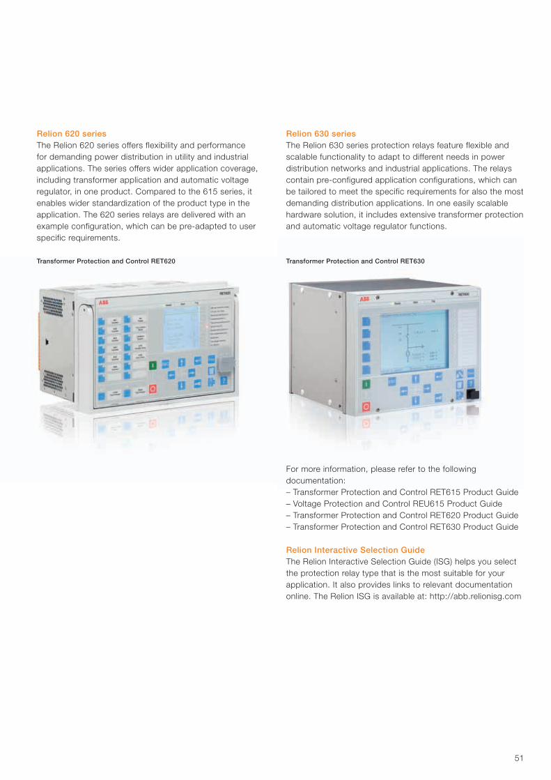
51
Relion 620 seriesThe Relion 620 series offers flexibility and performance for demanding power distribution in utility and industrial applications. The series offers wider application coverage, including transformer application and automatic voltage regulator, in one product. Compared to the 615 series, it enables wider standardization of the product type in the application. The 620 series relays are delivered with an example configuration, which can be pre-adapted to user specific requirements.
Transformer Protection and Control RET620 Transformer Protection and Control RET630
Relion 630 seriesThe Relion 630 series protection relays feature flexible and scalable functionality to adapt to different needs in power distribution networks and industrial applications. The relays contain pre-configured application configurations, which can be tailored to meet the specific requirements for also the most demanding distribution applications. In one easily scalable hardware solution, it includes extensive transformer protection and automatic voltage regulator functions.
For more information, please refer to the following documentation:– Transformer Protection and Control RET615 Product Guide– Voltage Protection and Control REU615 Product Guide– Transformer Protection and Control RET620 Product Guide– Transformer Protection and Control RET630 Product Guide
Relion Interactive Selection GuideThe Relion Interactive Selection Guide (ISG) helps you select the protection relay type that is the most suitable for your application. It also provides links to relevant documentation online. The Relion ISG is available at: http://abb.relionisg.com
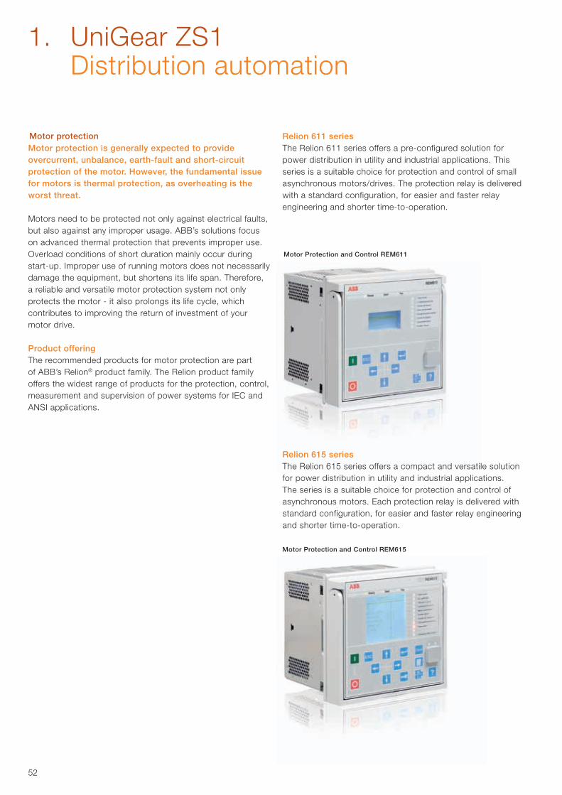
52
Motor Protection and Control REM615
Motor protectionMotor protection is generally expected to provide overcurrent, unbalance, earth-fault and short-circuit protection of the motor. However, the fundamental issue for motors is thermal protection, as overheating is the worst threat.
Motors need to be protected not only against electrical faults, but also against any improper usage. ABB’s solutions focus on advanced thermal protection that prevents improper use. Overload conditions of short duration mainly occur during start-up. Improper use of running motors does not necessarily damage the equipment, but shortens its life span. Therefore, a reliable and versatile motor protection system not only protects the motor - it also prolongs its life cycle, which contributes to improving the return of investment of your motor drive.
Product offeringThe recommended products for motor protection are part of ABB’s Relion® product family. The Relion product family offers the widest range of products for the protection, control, measurement and supervision of power systems for IEC and ANSI applications.
Motor Protection and Control REM611
Relion 611 seriesThe Relion 611 series offers a pre-configured solution for power distribution in utility and industrial applications. This series is a suitable choice for protection and control of small asynchronous motors/drives. The protection relay is delivered with a standard configuration, for easier and faster relay engineering and shorter time-to-operation.
Relion 615 seriesThe Relion 615 series offers a compact and versatile solution for power distribution in utility and industrial applications. The series is a suitable choice for protection and control of asynchronous motors. Each protection relay is delivered with standard configuration, for easier and faster relay engineering and shorter time-to-operation.
1. UniGear ZS1 Distribution automation
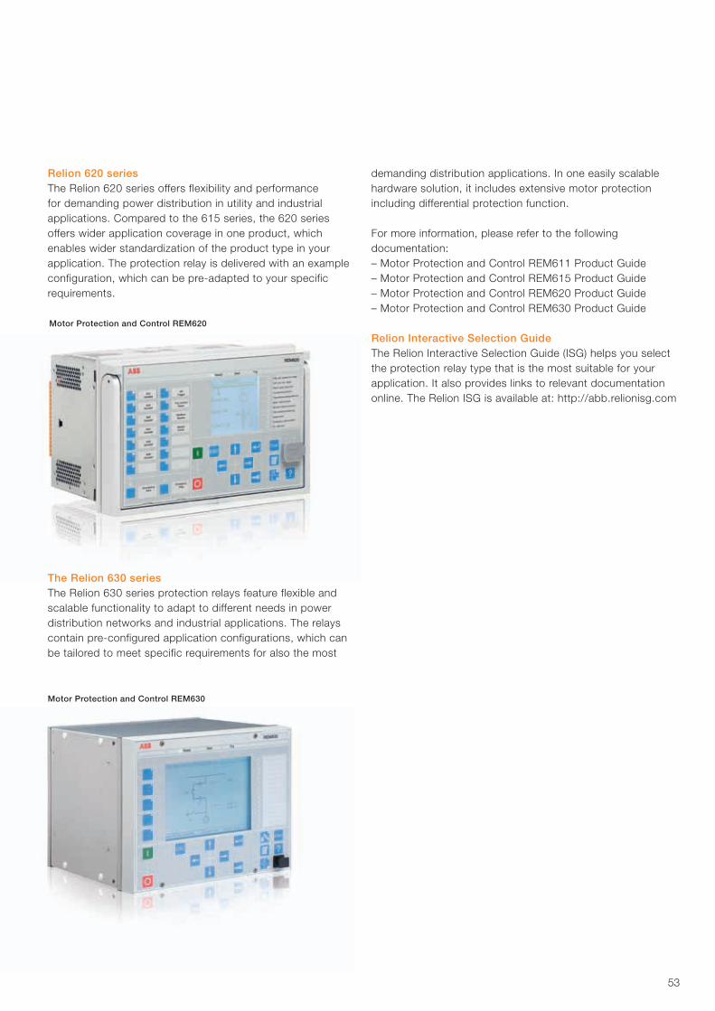
53
Relion 620 seriesThe Relion 620 series offers flexibility and performance for demanding power distribution in utility and industrial applications. Compared to the 615 series, the 620 series offers wider application coverage in one product, which enables wider standardization of the product type in your application. The protection relay is delivered with an example configuration, which can be pre-adapted to your specific requirements.
The Relion 630 seriesThe Relion 630 series protection relays feature flexible and scalable functionality to adapt to different needs in power distribution networks and industrial applications. The relays contain pre-configured application configurations, which can be tailored to meet specific requirements for also the most
demanding distribution applications. In one easily scalable hardware solution, it includes extensive motor protection including differential protection function.
For more information, please refer to the following documentation:– Motor Protection and Control REM611 Product Guide– Motor Protection and Control REM615 Product Guide– Motor Protection and Control REM620 Product Guide– Motor Protection and Control REM630 Product Guide
Relion Interactive Selection GuideThe Relion Interactive Selection Guide (ISG) helps you select the protection relay type that is the most suitable for your application. It also provides links to relevant documentation online. The Relion ISG is available at: http://abb.relionisg.com
Motor Protection and Control REM620
Motor Protection and Control REM630
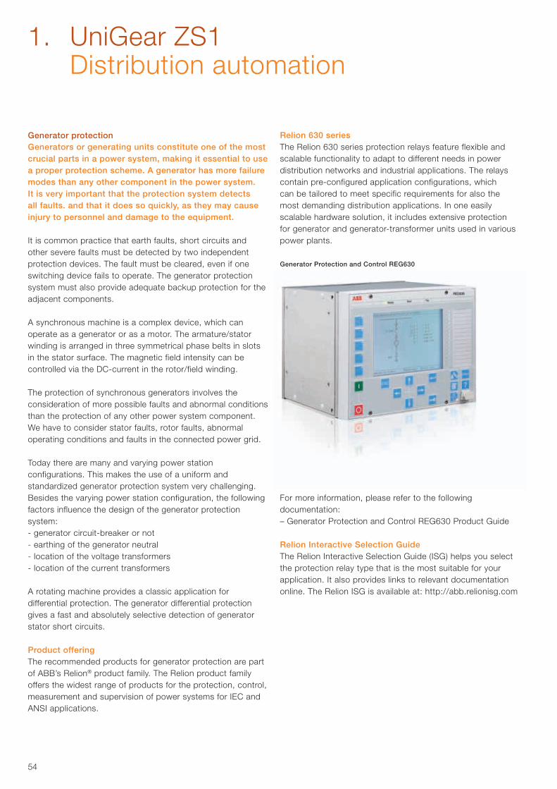
54
Generator protectionGenerators or generating units constitute one of the most crucial parts in a power system, making it essential to use a proper protection scheme. A generator has more failure modes than any other component in the power system. It is very important that the protection system detects all faults. and that it does so quickly, as they may cause injury to personnel and damage to the equipment.
It is common practice that earth faults, short circuits and other severe faults must be detected by two independent protection devices. The fault must be cleared, even if one switching device fails to operate. The generator protection system must also provide adequate backup protection for the adjacent components.
A synchronous machine is a complex device, which can operate as a generator or as a motor. The armature/stator winding is arranged in three symmetrical phase belts in slots in the stator surface. The magnetic field intensity can be controlled via the DC-current in the rotor/field winding.
The protection of synchronous generators involves the consideration of more possible faults and abnormal conditions than the protection of any other power system component. We have to consider stator faults, rotor faults, abnormal operating conditions and faults in the connected power grid.
Today there are many and varying power station configurations. This makes the use of a uniform and standardized generator protection system very challenging. Besides the varying power station configuration, the following factors influence the design of the generator protection system:- generator circuit-breaker or not- earthing of the generator neutral- location of the voltage transformers- location of the current transformers
A rotating machine provides a classic application for differential protection. The generator differential protection gives a fast and absolutely selective detection of generator stator short circuits.
Product offeringThe recommended products for generator protection are part of ABB’s Relion® product family. The Relion product family offers the widest range of products for the protection, control, measurement and supervision of power systems for IEC and ANSI applications.
Generator Protection and Control REG630
Relion 630 seriesThe Relion 630 series protection relays feature flexible and scalable functionality to adapt to different needs in power distribution networks and industrial applications. The relays contain pre-configured application configurations, which can be tailored to meet specific requirements for also the most demanding distribution applications. In one easily scalable hardware solution, it includes extensive protection for generator and generator-transformer units used in various power plants.
For more information, please refer to the following documentation:– Generator Protection and Control REG630 Product Guide
Relion Interactive Selection GuideThe Relion Interactive Selection Guide (ISG) helps you select the protection relay type that is the most suitable for your application. It also provides links to relevant documentation online. The Relion ISG is available at: http://abb.relionisg.com
1. UniGear ZS1 Distribution automation
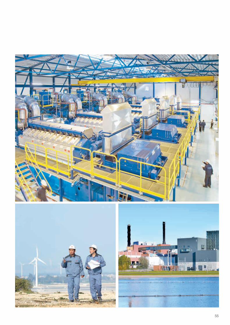
55
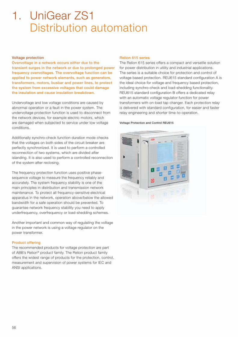
56
Voltage protectionOvervoltage in a network occurs either due to the transient surges in the network or due to prolonged power frequency overvoltages. The overvoltage function can be applied to power network elements, such as generators, transformers, motors, busbar and power lines, to protect the system from excessive voltages that could damage the insulation and cause insulation breakdown.
Undervoltage and low voltage conditions are caused by abnormal operation or a fault in the power system. The undervoltage protection function is used to disconnect from the network devices, for example electric motors, which are damaged when subjected to service under low voltage conditions.
Additionally synchro-check function duration mode checks that the voltages on both sides of the circuit breaker are perfectly synchronized. It is used to perform a controlled reconnection of two systems, which are divided after islanding. It is also used to perform a controlled reconnection of the system after reclosing.
The frequency protection function uses positive phase- sequence voltage to measure the frequency reliably and accurately. The system frequency stability is one of the main principles in distribution and transmission network maintenance. To protect all frequency-sensitive electrical apparatus in the network, operation above/below the allowed bandwidth for a safe operation should be prevented. To guarantee network frequency stability you need to apply underfrequency, overfrequency or load-shedding schemes.
Another important and common way of regulating the voltage in the power network is using a voltage regulator on the power transformer.
Product offeringThe recommended products for voltage protection are part of ABB’s Relion® product family. The Relion product family offers the widest range of products for the protection, control, measurement and supervision of power systems for IEC and ANSI applications.
Relion 615 seriesThe Relion 615 series offers a compact and versatile solution for power distribution in utility and industrial applications.The series is a suitable choice for protection and control of voltage based protection. REU615 standard configuration A is the ideal choice for voltage and frequency based protection, including synchro-check and load-shedding functionality. REU615 standard configuration B offers a dedicated relay with an automatic voltage regulator function for power transformers with on-load tap changer. Each protection relay is delivered with standard configuration, for easier and faster relay engineering and shorter time-to-operation.
Voltage Protection and Control REU615
1. UniGear ZS1 Distribution automation
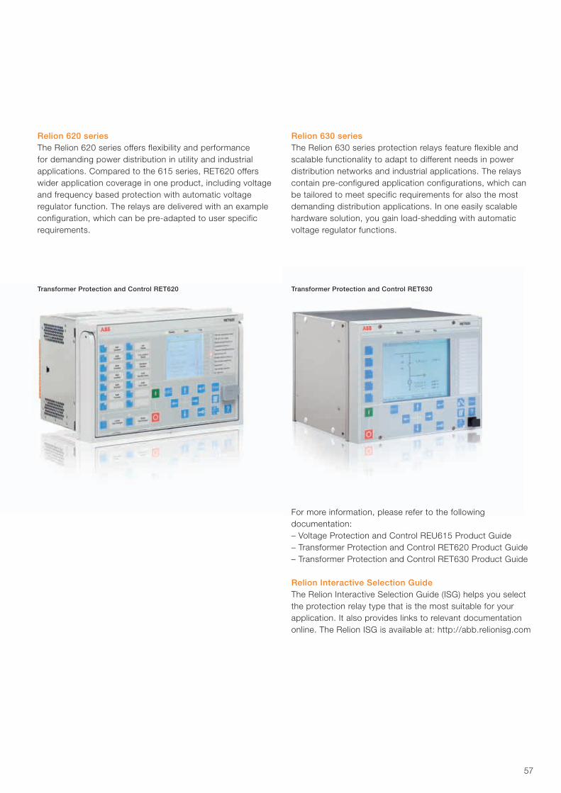
57
Relion 620 seriesThe Relion 620 series offers flexibility and performance for demanding power distribution in utility and industrial applications. Compared to the 615 series, RET620 offers wider application coverage in one product, including voltage and frequency based protection with automatic voltage regulator function. The relays are delivered with an example configuration, which can be pre-adapted to user specific requirements.
Transformer Protection and Control RET620 Transformer Protection and Control RET630
Relion 630 seriesThe Relion 630 series protection relays feature flexible and scalable functionality to adapt to different needs in power distribution networks and industrial applications. The relays contain pre-configured application configurations, which can be tailored to meet specific requirements for also the most demanding distribution applications. In one easily scalable hardware solution, you gain load-shedding with automatic voltage regulator functions.
For more information, please refer to the following documentation:– Voltage Protection and Control REU615 Product Guide– Transformer Protection and Control RET620 Product Guide– Transformer Protection and Control RET630 Product Guide
Relion Interactive Selection GuideThe Relion Interactive Selection Guide (ISG) helps you select the protection relay type that is the most suitable for your application. It also provides links to relevant documentation online. The Relion ISG is available at: http://abb.relionisg.com
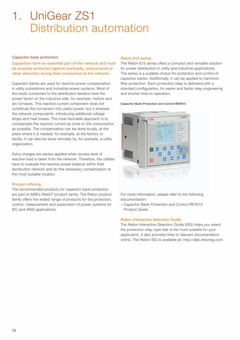
58
Capacitor bank protection
Capacitors form an essential part of the network and must be properly protected against overloads, overcurrents or other distortion during their connection to the network.
Capacitor banks are used for reactive power compensation in utility substations and industrial power systems. Most of the loads connected to the distribution feeders have the power factor on the inductive side, for example, motors and arc furnaces. This reactive current component does not contribute the conversion into useful power, but it stresses the network components, introducing additional voltage drops and heat losses. The most favorable approach is to compensate the reactive current as close to the consumption as possible. The compensation can be done locally, at the place where it is needed, for example, at the factory or facility. It can also be done remotely by, for example, a utility organization.
Extra charges are always applied when excess level of reactive load is taken from the network. Therefore, the utilities have to evaluate the reactive power balance within their distribution network and do the necessary compensation at the most suitable location.
Product offeringThe recommended products for capacitor bank protection are part of ABB’s Relion® product family. The Relion product family offers the widest range of products for the protection, control, measurement and supervision of power systems forIEC and ANSI applications.
Capacitor Bank Protection and Control REV615
Relion 615 seriesThe Relion 615 series offers a compact and versatile solution for power distribution in utility and industrial applications. The series is a suitable choice for protection and control of capacitor banks. Additionally, it can be applied to harmonic filter protection. Each protection relay is delivered with a standard configuration, for easier and faster relay engineering and shorter time-to-operation.
For more information, please refer to the following documentation:– Capacitor Bank Protection and Control REV615
Product Guide
Relion Interactive Selection GuideThe Relion Interactive Selection Guide (ISG) helps you select the protection relay type that is the most suitable for your application. It also provides links to relevant documentation online. The Relion ISG is available at: http://abb.relionisg.com
1. UniGear ZS1 Distribution automation
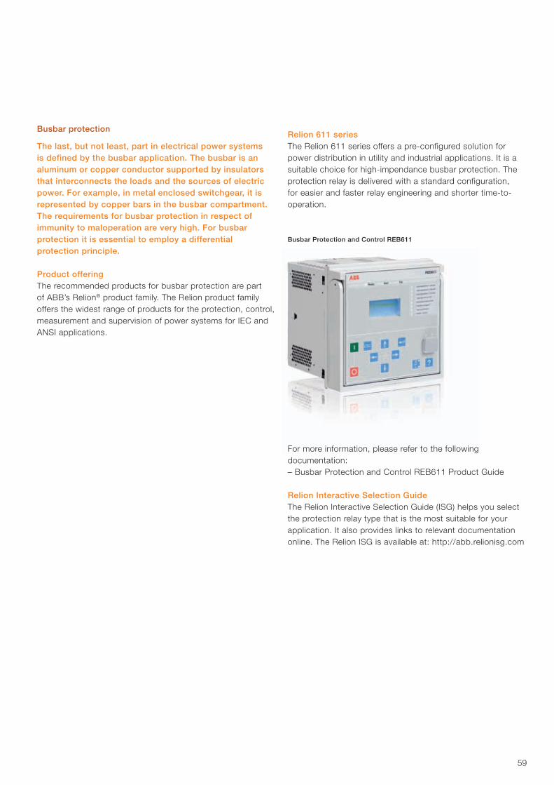
59
Busbar protection
The last, but not least, part in electrical power systems is defined by the busbar application. The busbar is an aluminum or copper conductor supported by insulators that interconnects the loads and the sources of electric power. For example, in metal enclosed switchgear, it is represented by copper bars in the busbar compartment. The requirements for busbar protection in respect of immunity to maloperation are very high. For busbar protection it is essential to employ a differential protection principle.
Product offeringThe recommended products for busbar protection are part of ABB’s Relion® product family. The Relion product family offers the widest range of products for the protection, control, measurement and supervision of power systems for IEC and ANSI applications.
Busbar Protection and Control REB611
Relion 611 seriesThe Relion 611 series offers a pre-configured solution for power distribution in utility and industrial applications. It is a suitable choice for high-impendance busbar protection. The protection relay is delivered with a standard configuration, for easier and faster relay engineering and shorter time-to-operation.
For more information, please refer to the following documentation:– Busbar Protection and Control REB611 Product Guide
Relion Interactive Selection GuideThe Relion Interactive Selection Guide (ISG) helps you select the protection relay type that is the most suitable for your application. It also provides links to relevant documentation online. The Relion ISG is available at: http://abb.relionisg.com
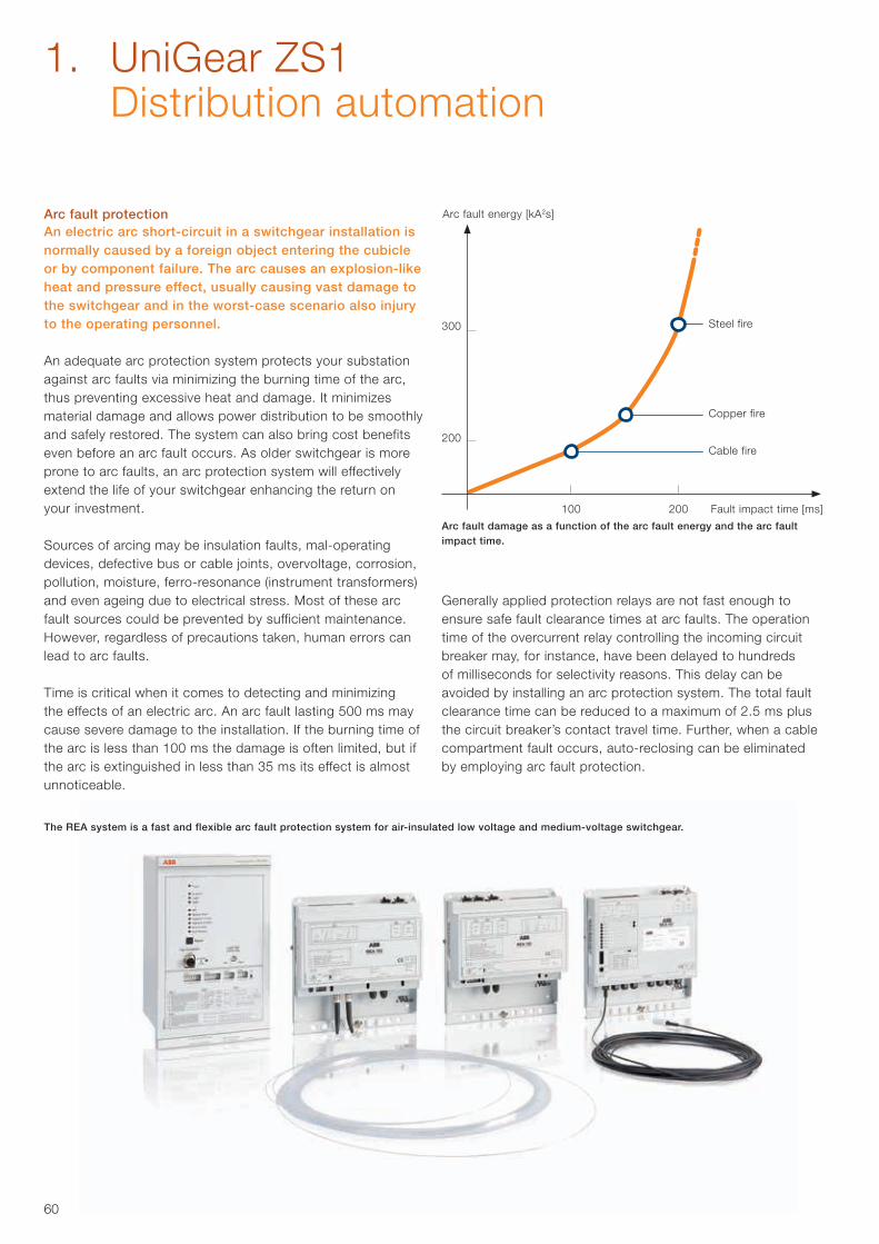
60
Arc fault protectionAn electric arc short-circuit in a switchgear installation is normally caused by a foreign object entering the cubicle or by component failure. The arc causes an explosion-like heat and pressure effect, usually causing vast damage to the switchgear and in the worst-case scenario also injury to the operating personnel.
An adequate arc protection system protects your substation against arc faults via minimizing the burning time of the arc, thus preventing excessive heat and damage. It minimizes material damage and allows power distribution to be smoothly and safely restored. The system can also bring cost benefits even before an arc fault occurs. As older switchgear is more prone to arc faults, an arc protection system will effectively extend the life of your switchgear enhancing the return on your investment.
Sources of arcing may be insulation faults, mal-operating devices, defective bus or cable joints, overvoltage, corrosion, pollution, moisture, ferro-resonance (instrument transformers) and even ageing due to electrical stress. Most of these arc fault sources could be prevented by sufficient maintenance. However, regardless of precautions taken, human errors can lead to arc faults.
Time is critical when it comes to detecting and minimizing the effects of an electric arc. An arc fault lasting 500 ms may cause severe damage to the installation. If the burning time of the arc is less than 100 ms the damage is often limited, but if the arc is extinguished in less than 35 ms its effect is almost unnoticeable.
Generally applied protection relays are not fast enough to ensure safe fault clearance times at arc faults. The operation time of the overcurrent relay controlling the incoming circuit breaker may, for instance, have been delayed to hundreds of milliseconds for selectivity reasons. This delay can be avoided by installing an arc protection system. The total fault clearance time can be reduced to a maximum of 2.5 ms plus the circuit breaker’s contact travel time. Further, when a cable compartment fault occurs, auto-reclosing can be eliminated by employing arc fault protection.
Steel fire
Copper fire
Cable fire
100 200
Arc fault energy [kA2s]
200
300
Fault impact time [ms]
Arc fault damage as a function of the arc fault energy and the arc fault impact time.
The REA system is a fast and flexible arc fault protection system for air-insulated low voltage and medium-voltage switchgear.
1. UniGear ZS1 Distribution automation
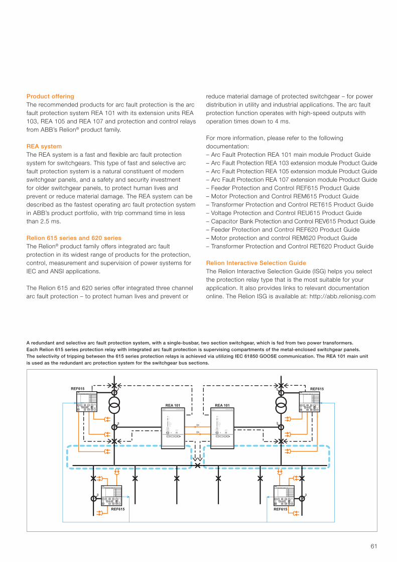
61
Product offeringThe recommended products for arc fault protection is the arc fault protection system REA 101 with its extension units REA103, REA 105 and REA 107 and protection and control relays from ABB’s Relion® product family.
REA systemThe REA system is a fast and flexible arc fault protection system for switchgears. This type of fast and selective arc fault protection system is a natural constituent of modern switchgear panels, and a safety and security investment for older switchgear panels, to protect human lives and prevent or reduce material damage. The REA system can be described as the fastest operating arc fault protection system in ABB’s product portfolio, with trip command time in less than 2.5 ms.
Relion 615 series and 620 seriesThe Relion® product family offers integrated arc fault protection in its widest range of products for the protection, control, measurement and supervision of power systems for IEC and ANSI applications.
The Relion 615 and 620 series offer integrated three channelarc fault protection – to protect human lives and prevent or
reduce material damage of protected switchgear – for power distribution in utility and industrial applications. The arc fault protection function operates with high-speed outputs with operation times down to 4 ms.
For more information, please refer to the following documentation:– Arc Fault Protection REA 101 main module Product Guide– Arc Fault Protection REA 103 extension module Product Guide– Arc Fault Protection REA 105 extension module Product Guide– Arc Fault Protection REA 107 extension module Product Guide– Feeder Protection and Control REF615 Product Guide– Motor Protection and Control REM615 Product Guide– Transformer Protection and Control RET615 Product Guide– Voltage Protection and Control REU615 Product Guide– Capacitor Bank Protection and Control REV615 Product Guide– Feeder Protection and Control REF620 Product Guide– Motor protection and control REM620 Product Guide– Transformer Protection and Control RET620 Product Guide
Relion Interactive Selection GuideThe Relion Interactive Selection Guide (ISG) helps you select the protection relay type that is the most suitable for your application. It also provides links to relevant documentation online. The Relion ISG is available at: http://abb.relionisg.com
Ready Start Trip
ESC Clear
RL ?
Ready Start Trip
ESC Clear
RL ?
REF615Ready Start Trip
ESC Clear
RL ?
REF615
REF615REF615
REA 101 REA 101
Ready Start Trip
ESC Clear
RL ?
A redundant and selective arc fault protection system, with a single-busbar, two section switchgear, which is fed from two power transformers. Each Relion 615 series protection relay with integrated arc fault protection is supervising compartments of the metal-enclosed switchgear panels. The selectivity of tripping between the 615 series protection relays is achieved via utilizing IEC 61850 GOOSE communication. The REA 101 main unit is used as the redundant arc protection system for the switchgear bus sections.
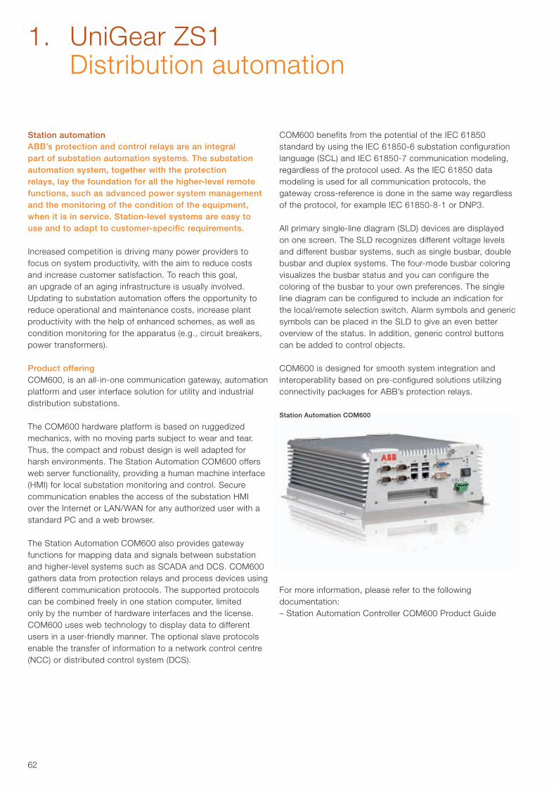
62
Station automationABB’s protection and control relays are an integral part of substation automation systems. The substation automation system, together with the protection relays, lay the foundation for all the higher-level remote functions, such as advanced power system management and the monitoring of the condition of the equipment, when it is in service. Station-level systems are easy to use and to adapt to customer-specific requirements.
Increased competition is driving many power providers to focus on system productivity, with the aim to reduce costs and increase customer satisfaction. To reach this goal, an upgrade of an aging infrastructure is usually involved. Updating to substation automation offers the opportunity to reduce operational and maintenance costs, increase plant productivity with the help of enhanced schemes, as well as condition monitoring for the apparatus (e.g., circuit breakers, power transformers).
Product offeringCOM600, is an all-in-one communication gateway, automation platform and user interface solution for utility and industrial distribution substations.
The COM600 hardware platform is based on ruggedized mechanics, with no moving parts subject to wear and tear.Thus, the compact and robust design is well adapted for harsh environments. The Station Automation COM600 offers web server functionality, providing a human machine interface(HMI) for local substation monitoring and control. Secure communication enables the access of the substation HMI over the Internet or LAN/WAN for any authorized user with a standard PC and a web browser.
The Station Automation COM600 also provides gateway functions for mapping data and signals between substation and higher-level systems such as SCADA and DCS. COM600 gathers data from protection relays and process devices using different communication protocols. The supported protocols can be combined freely in one station computer, limited only by the number of hardware interfaces and the license. COM600 uses web technology to display data to different users in a user-friendly manner. The optional slave protocols enable the transfer of information to a network control centre (NCC) or distributed control system (DCS).
COM600 benefits from the potential of the IEC 61850 standard by using the IEC 61850-6 substation configuration language (SCL) and IEC 61850-7 communication modeling, regardless of the protocol used. As the IEC 61850 data modeling is used for all communication protocols, the gateway cross-reference is done in the same way regardless of the protocol, for example IEC 61850-8-1 or DNP3.
All primary single-line diagram (SLD) devices are displayed on one screen. The SLD recognizes different voltage levels and different busbar systems, such as single busbar, double busbar and duplex systems. The four-mode busbar coloring visualizes the busbar status and you can configure the coloring of the busbar to your own preferences. The single line diagram can be configured to include an indication for the local/remote selection switch. Alarm symbols and generic symbols can be placed in the SLD to give an even better overview of the status. In addition, generic control buttons can be added to control objects.
COM600 is designed for smooth system integration and interoperability based on pre-configured solutions utilizing connectivity packages for ABB’s protection relays.
For more information, please refer to the following documentation:– Station Automation Controller COM600 Product Guide
Station Automation COM600
1. UniGear ZS1 Distribution automation
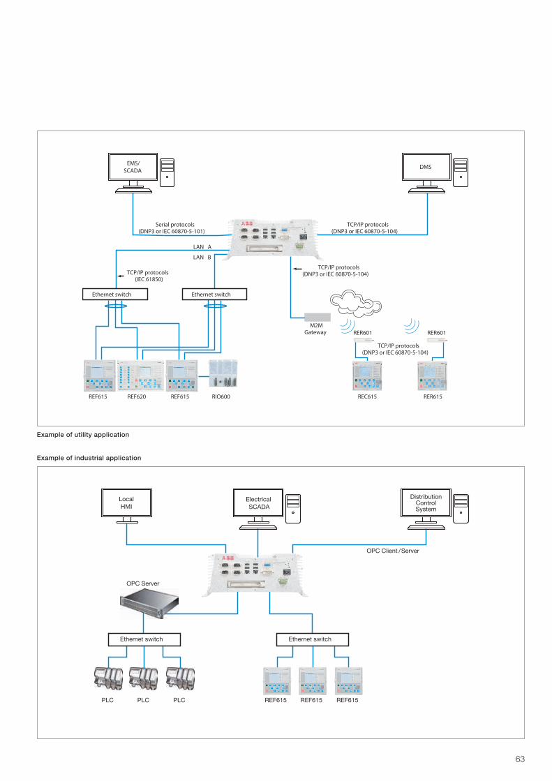
63
Ethernet switch Ethernet switch
M2MGateway
TCP/IP protocols(DNP3 or IEC 60870-5-104)
TCP/IP protocols(DNP3 or IEC 60870-5-104)
TCP/IP protocols(IEC 61850)
TCP/IP protocols(DNP3 or IEC 60870-5-104)
Serial protocols(DNP3 or IEC 60870-5-101)
LAN A
LAN B
REF615 RIO600REF620 REC615 RER615
RER601 RER601
REF615
EMS/SCADA
DMS
REF615 REF615REF615PLC PLCPLC
Ethernet switchEthernet switch
OPC Server
OPC Client / Server
LocalHMI
ElectricalSCADA
DistributionControlSystem
Example of utility application
Example of industrial application
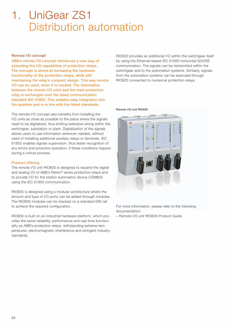
64
Remote I/O concept
ABB’s remote I/O concept introduces a new way of extending the I/O capabilities of protection relays. The concept is aimed at increasing the hardware functionality of the protection relays, while still maintaining the relay’s compact design. This way remote I/O can be used, when it is needed. The information between the remote I/O units and the main protection relay is exchanged over the latest communication standard IEC 61850. This enables easy integration into the systems and is in line with the latest standards.
The remote I/O concept also benefits from installing the I/O units as close as possible to the place where the signals need to be digitalized, thus limiting extensive wiring within the switchgear, substation or plant. Digitalization of the signals allows users to use information wherever needed, without need of installing additional auxiliary relays or terminals. IEC 61850 enables signals supervision, thus faster recognition of any errors and proactive operation, if these conditions happen during a critical process.
Product offeringThe remote I/O unit RIO600 is designed to expand the digital and analog I/O of ABB’s Relion® series protection relays and to provide I/O for the station automation device COM600 using the IEC 61850 communication.
RIO600 is designed using a modular architecture where the amount and type of I/O ports can be added through modules. The RIO600 modules can be stacked on a standard DIN rail to achieve the required configuration.
RIO600 is built on an industrial hardware platform, which pro-vides the same reliability, performance and real-time function-ality as ABB’s protection relays, withstanding extreme tem-peratures, electromagnetic interference and stringent industry standards.
RIO600 provides an additional I/O within the switchgear itself by using the Ethernet-based IEC 61850 horizontal GOOSE communication. The signals can be transmitted within the switchgear and to the automation systems. Similarly, signals from the automation systems can be executed through RIO600 connected to numerical protection relays.
For more information, please refer to the following documentation:– Remote I/O unit RIO600 Product Guide
Remote I/O unit RIO600
1. UniGear ZS1 Distribution automation

65
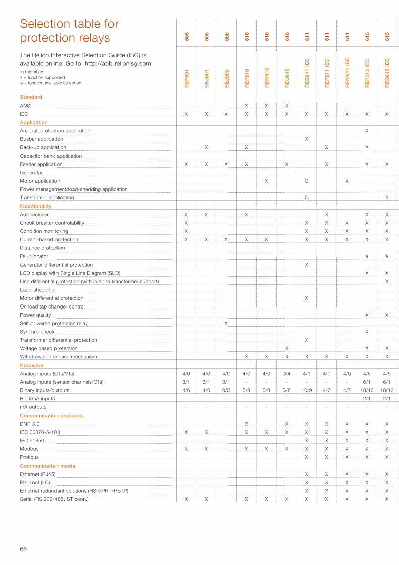
66
Standard
ANSI
IEC
Application
Arc fault protection application
Busbar application
Back-up application
Capacitor bank application
Feeder application
Generator
Motor application
Power management/load-shedding application
Transformer application
Functionality
Autorecloser
Circuit breaker controlability
Condition monitoring
Current-based protection
Distance protection
Fault locator
Generator differential protection
LCD display with Single Line Diagram (SLD)
Line differential protection (with in-zone transformer support)
Load-shedding
Motor differential protection
On load tap changer control
Power quality
Self-powered protection relay
Synchro-check
Transformer differential protection
Voltage based protection
Withdrawable release mechanism
Hardware
Analog inputs (CTs/VTs)
Analog inputs (sensor channels/CTs)
Binary inputs/outputs
RTD/mA inputs
mA outputs
Communication protocols
DNP 3.0
IEC 60870-5-103
IEC 61850
Modbus
Profibus
Communication media
Ethernet (RJ45)
Ethernet (LC)
Ethernet redundant solutions (HSR/PRP/RSTP)
Serial (RS 232/485, ST conn.)
X
X
X
X
X
X
4/0
-
4/7
-
-
X
X
X
X
X
X
X
X
X
X
X
X
X
X
X
X
X
X
X
X
X
X
X
4/5
6/1
18/13
2/1
-
X
X
X
X
X
X
X
X
X
X
X
X
X
X
0/4
-
5/8
-
-
X
X
X
X
X
X
O
O
X
X
X
X
X
X
X
4/1
-
10/9
-
-
X
X
X
X
X
X
X
X
X
X
X
X
X
X
X
X
4/0
-
5/8
-
-
X
X
X
X
X
X
X
X
X
X
4/0
3/1
4/6
-
-
X
X
X
Selection table for protection relays
RE
F60
1
RE
J601
RE
J603
RE
F61
0
RE
M61
0
RE
U61
0
RE
B61
1 IE
C
RE
F61
1 IE
C
RE
M61
1 IE
C
RE
F61
5 IE
C
RE
D61
5 IE
C
RE
M61
5 IE
C
RE
T61
5 IE
C
RE
U61
5 IE
C
RE
V61
5 IE
C
RE
F61
5 A
NS
I
RE
F61
5R A
NS
I
RE
M61
5 A
NS
I
RE
T61
5 A
NS
I
RE
F62
0 IE
C
RE
M62
0 IE
C
RE
T62
0 IE
C
RE
F62
0 A
NS
I
RE
M62
0 A
NS
I
RE
T62
0 A
NS
I
RE
F63
0 IE
C
RE
M63
0 IE
C
RE
T63
0 IE
C
RE
G63
0 IE
C
605
605
605
610
610
610
611
611
611
615
615
615
615
615
615
615
615
615
615
620
620
620
620
620
620
630
630
630
630
X
X
X
X
X
4/0
3/1
4/6
-
-
X
X
X
X
X
X
X
4/0
3/1
0/2
-
-
X
X
X
X
X
4/0
-
5/8
-
-
X
X
X
The Relion Interactive Selection Guide (ISG) is available online. Go to: http://abb.relionisg.comIn the table:x = function supportedo = function available as option
X
X
X
X
X
X
X
X
4/0
-
4/7
-
-
X
X
X
X
X
X
X
X
X
X
X
X
X
X
X
X
X
X
X
X
X
X
4/5
6/1
18/13
2/1
-
X
X
X
X
X
X
X
X
X
X
X
X
X
X
X
X
X
X
4/5
6/1
16/12
6/2
-
X
X
X
X
X
X
X
X
X
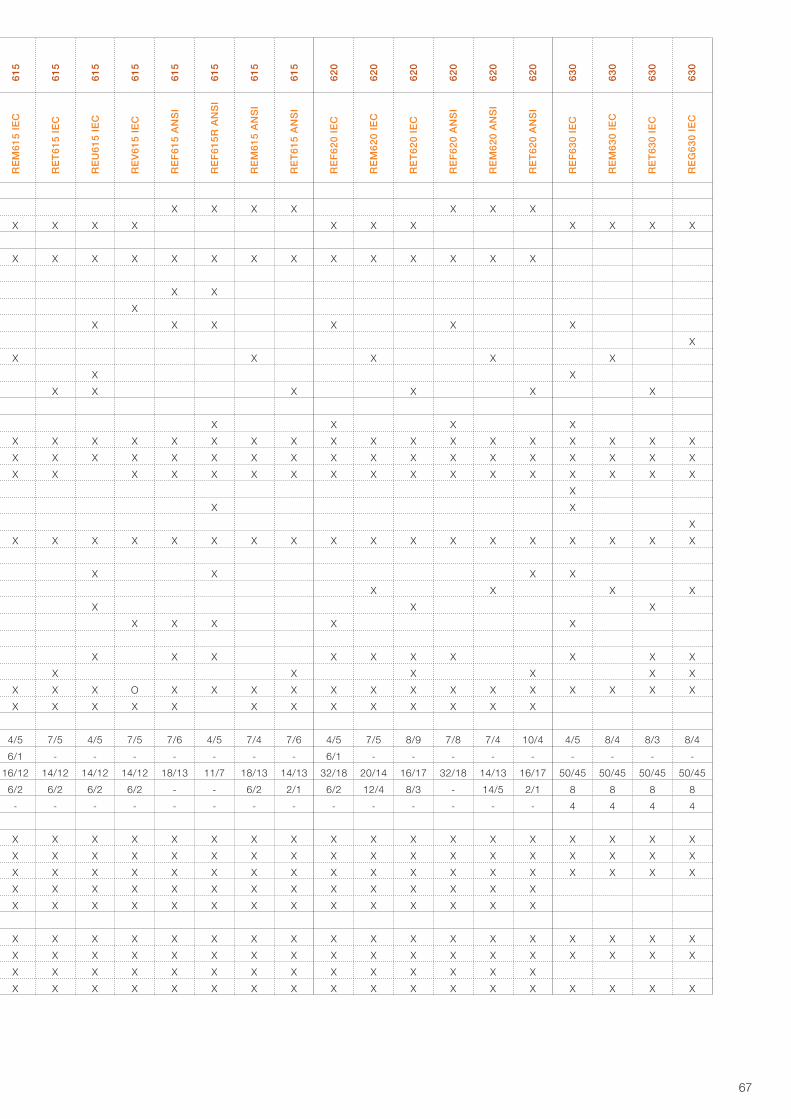
67
Standard
ANSI
IEC
Application
Arc fault protection application
Busbar application
Back-up application
Capacitor bank application
Feeder application
Generator
Motor application
Power management/load-shedding application
Transformer application
Functionality
Autorecloser
Circuit breaker controlability
Condition monitoring
Current-based protection
Distance protection
Fault locator
Generator differential protection
LCD display with Single Line Diagram (SLD)
Line differential protection (with in-zone transformer support)
Load-shedding
Motor differential protection
On load tap changer control
Power quality
Self-powered protection relay
Synchro-check
Transformer differential protection
Voltage based protection
Withdrawable release mechanism
Hardware
Analog inputs (CTs/VTs)
Analog inputs (sensor channels/CTs)
Binary inputs/outputs
RTD/mA inputs
mA outputs
Communication protocols
DNP 3.0
IEC 60870-5-103
IEC 61850
Modbus
Profibus
Communication media
Ethernet (RJ45)
Ethernet (LC)
Ethernet redundant solutions (HSR/PRP/RSTP)
Serial (RS 232/485, ST conn.)
RE
F60
1
RE
J601
RE
J603
RE
F61
0
RE
M61
0
RE
U61
0
RE
B61
1 IE
C
RE
F61
1 IE
C
RE
M61
1 IE
C
RE
F61
5 IE
C
RE
D61
5 IE
C
RE
M61
5 IE
C
RE
T61
5 IE
C
RE
U61
5 IE
C
RE
V61
5 IE
C
RE
F61
5 A
NS
I
RE
F61
5R A
NS
I
RE
M61
5 A
NS
I
RE
T61
5 A
NS
I
RE
F62
0 IE
C
RE
M62
0 IE
C
RE
T62
0 IE
C
RE
F62
0 A
NS
I
RE
M62
0 A
NS
I
RE
T62
0 A
NS
I
RE
F63
0 IE
C
RE
M63
0 IE
C
RE
T63
0 IE
C
RE
G63
0 IE
C
605
605
605
610
610
610
611
611
611
615
615
615
615
615
615
615
615
615
615
620
620
620
620
620
620
630
630
630
630
X
X
X
X
X
X
X
X
X
4/5
6/1
16/12
6/2
-
X
X
X
X
X
X
X
X
X
X
X
X
X
X
X
X
X
X
X
7/5
-
14/12
6/2
-
X
X
X
X
X
X
X
X
X
X
X
X
X
X
X
X
X
X
X
X
X
X
4/5
-
14/12
6/2
-
X
X
X
X
X
X
X
X
X
X
X
X
X
X
X
X
X
O
X
7/5
-
14/12
6/2
-
X
X
X
X
X
X
X
X
X
X
X
X
X
X
X
X
X
X
X
X
X
7/6
-
18/13
-
-
X
X
X
X
X
X
X
X
X
X
X
X
X
X
X
X
X
X
X
X
X
X
X
4/5
-
11/7
-
-
X
X
X
X
X
X
X
X
X
X
X
X
X
X
X
X
X
X
7/4
-
18/13
6/2
-
X
X
X
X
X
X
X
X
X
X
X
X
X
X
X
X
X
X
X
7/6
-
14/13
2/1
-
X
X
X
X
X
X
X
X
X
X
X
X
X
X
X
X
X
X
X
X
X
4/5
6/1
32/18
6/2
-
X
X
X
X
X
X
X
X
X
X
X
X
X
X
X
X
X
X
X
X
7/5
-
20/14
12/4
-
X
X
X
X
X
X
X
X
X
X
X
X
X
X
X
X
X
X
X
X
X
8/9
-
16/17
8/3
-
X
X
X
X
X
X
X
X
X
X
X
X
X
X
X
X
X
X
X
X
7/8
-
32/18
-
-
X
X
X
X
X
X
X
X
X
X
X
X
X
X
X
X
X
X
X
7/4
-
14/13
14/5
-
X
X
X
X
X
X
X
X
X
X
X
X
X
X
X
X
X
X
X
X
10/4
-
16/17
2/1
-
X
X
X
X
X
X
X
X
X
X
X
X
X
X
X
X
X
X
X
X
X
X
X
4/5
-
50/45
8
4
X
X
X
X
X
X
X
X
X
X
X
X
X
X
8/4
-
50/45
8
4
X
X
X
X
X
X
X
X
X
X
X
X
X
X
X
X
8/3
-
50/45
8
4
X
X
X
X
X
X
X
X
X
X
X
X
X
X
X
X
X
8/4
-
50/45
8
4
X
X
X
X
X
X
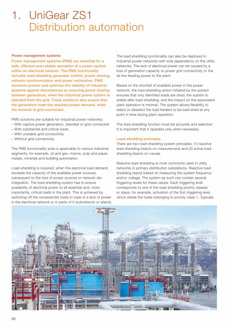
68
Power management systems
Power management systems (PMS) are essential for a safe, efficient and reliable operation of a power system within an electrical network. The PMS functionality includes load-shedding generator control, power sharing, network synchronization and power restoration. PMS solutions protect and optimize the stability of industrial systems against disturbances by ensuring power sharing between generators, when the industrial power system is islanded from the grid. These solutions also ensure that the generators meet the required power demand, when the network is grid-connected.
PMS solutions are suitable for industrial power networks:– With captive power generation, islanded or grid-connected– With substantial and critical loads– With unstable grid connectivity– Without grid connectivity
The PMS functionality suite is applicable to various industrial segments, for example, oil and gas, marine, pulp and paper, metals, minerals and building automation.
Load-shedding is required, when the electrical load demand exceeds the capacity of the available power sources, subsequent to the loss of power sources or network dis-integration. The load-shedding system has to ensure availability of electrical power to all essential and, most importantly, critical loads in the plant. This is achieved by switching off the nonessential loads in case of a lack of power in the electrical network or in parts of it (subnetwork or island).
The load-shedding functionality can also be deployed in industrial power networks with sole dependency on the utility networks. The lack of electrical power can be caused by a loss of generation capacity or power grid connectivity or the tie line feeding power to the plant.
Based on the shortfall of available power in the power network, the load-shedding action initiated by the system ensures that only identified loads are shed, the system is stable after load-shedding, and the impact on the associated plant operation is minimal. The system allows flexibility to select or deselect the load feeders to be load-shed at any point in time during plant operation.
The load-shedding function must be accurate and selective. It is important that it operates only when necessary.
Load-shedding principlesThere are two load-shedding system principles: (1) reactive load-shedding (reacts on measurement) and (2) active load-shedding (reacts on cause).
Reactive load-shedding is most commonly used in utility networks in primary distribution substations. Reactive load-shedding reacts based on measuring the system frequency and/or voltage. The system as such can contain several triggering levels for these values. Each triggering level corresponds to one of the load-shedding priority classes or steps, for example, activation of the first triggering level, which sheds the loads belonging to priority class 1. Typically
1. UniGear ZS1 Distribution automation
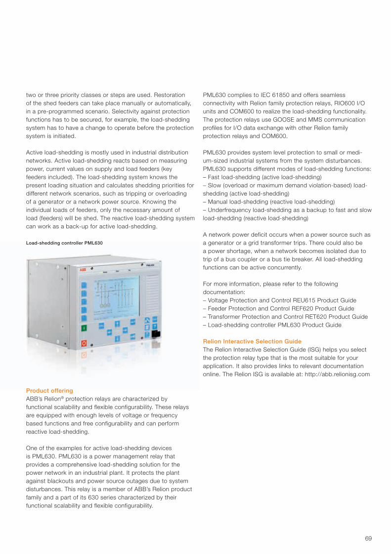
69
two or three priority classes or steps are used. Restoration of the shed feeders can take place manually or automatically, in a pre-programmed scenario. Selectivity against protection functions has to be secured, for example, the load-shedding system has to have a change to operate before the protection system is initiated.
Active load-shedding is mostly used in industrial distribution networks. Active load-shedding reacts based on measuring power, current values on supply and load feeders (key feeders included). The load-shedding system knows the present loading situation and calculates shedding priorities for different network scenarios, such as tripping or overloading of a generator or a network power source. Knowing the individual loads of feeders, only the necessary amount of load (feeders) will be shed. The reactive load-shedding system can work as a back-up for active load-shedding.
Product offeringABB’s Relion® protection relays are characterized by functional scalability and flexible configurability. These relays are equipped with enough levels of voltage or frequency based functions and free configurability and can perform reactive load-shedding.
One of the examples for active load-shedding devices is PML630. PML630 is a power management relay that provides a comprehensive load-shedding solution for the power network in an industrial plant. It protects the plant against blackouts and power source outages due to system disturbances. This relay is a member of ABB’s Relion product family and a part of its 630 series characterized by their functional scalability and flexible configurability.
PML630 complies to IEC 61850 and offers seamless connectivity with Relion family protection relays, RIO600 I/O units and COM600 to realize the load-shedding functionality.The protection relays use GOOSE and MMS communication profiles for I/O data exchange with other Relion family protection relays and COM600.
PML630 provides system level protection to small or medi-um-sized industrial systems from the system disturbances. PML630 supports different modes of load-shedding functions:– Fast load-shedding (active load-shedding) – Slow (overload or maximum demand violation-based) load-shedding (active load-shedding)– Manual load-shedding (reactive load-shedding)– Underfrequency load-shedding as a backup to fast and slow load-shedding (reactive load-shedding)
A network power deficit occurs when a power source such as a generator or a grid transformer trips. There could also be a power shortage, when a network becomes isolated due to trip of a bus coupler or a bus tie breaker. All load-shedding functions can be active concurrently.
For more information, please refer to the following documentation:– Voltage Protection and Control REU615 Product Guide– Feeder Protection and Control REF620 Product Guide– Transformer Protection and Control RET620 Product Guide– Load-shedding controller PML630 Product Guide
Relion Interactive Selection GuideThe Relion Interactive Selection Guide (ISG) helps you select the protection relay type that is the most suitable for your application. It also provides links to relevant documentation online. The Relion ISG is available at: http://abb.relionisg.com
Load-shedding controller PML630
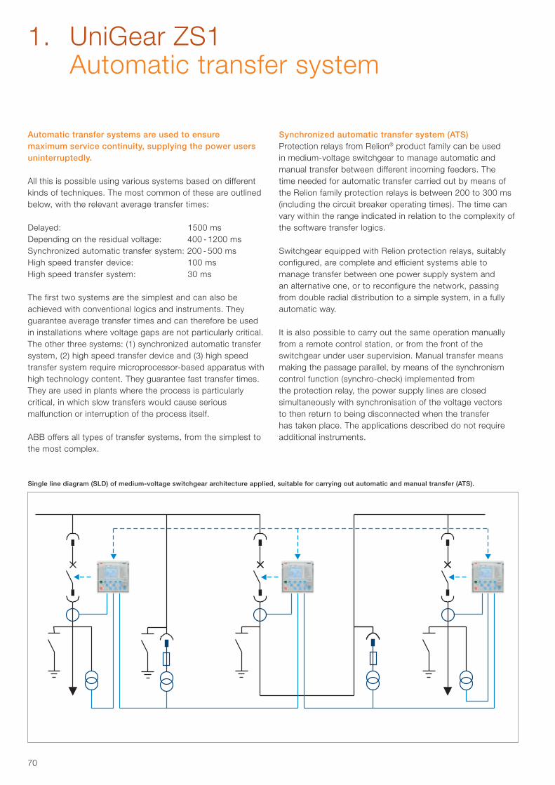
70
Automatic transfer systems are used to ensure maximum service continuity, supplying the power users uninterruptedly.
All this is possible using various systems based on different kinds of techniques. The most common of these are outlined below, with the relevant average transfer times:
Delayed: 1500 msDepending on the residual voltage: 400 - 1200 msSynchronized automatic transfer system: 200 - 500 msHigh speed transfer device: 100 msHigh speed transfer system: 30 ms
The first two systems are the simplest and can also be achieved with conventional logics and instruments. They guarantee average transfer times and can therefore be used in installations where voltage gaps are not particularly critical. The other three systems: (1) synchronized automatic transfer system, (2) high speed transfer device and (3) high speed transfer system require microprocessor-based apparatus with high technology content. They guarantee fast transfer times. They are used in plants where the process is particularly critical, in which slow transfers would cause serious malfunction or interruption of the process itself.
ABB offers all types of transfer systems, from the simplest to the most complex.
Synchronized automatic transfer system (ATS)Protection relays from Relion® product family can be used in medium-voltage switchgear to manage automatic and manual transfer between different incoming feeders. The time needed for automatic transfer carried out by means of the Relion family protection relays is between 200 to 300 ms (including the circuit breaker operating times). The time can vary within the range indicated in relation to the complexity of the software transfer logics.
Switchgear equipped with Relion protection relays, suitably configured, are complete and efficient systems able to manage transfer between one power supply system and an alternative one, or to reconfigure the network, passing from double radial distribution to a simple system, in a fully automatic way.
It is also possible to carry out the same operation manually from a remote control station, or from the front of the switchgear under user supervision. Manual transfer means making the passage parallel, by means of the synchronism control function (synchro-check) implemented from the protection relay, the power supply lines are closed simultaneously with synchronisation of the voltage vectors to then return to being disconnected when the transfer has taken place. The applications described do not require additional instruments.
Single line diagram (SLD) of medium-voltage switchgear architecture applied, suitable for carrying out automatic and manual transfer (ATS).
1. UniGear ZS1 Automatic transfer system
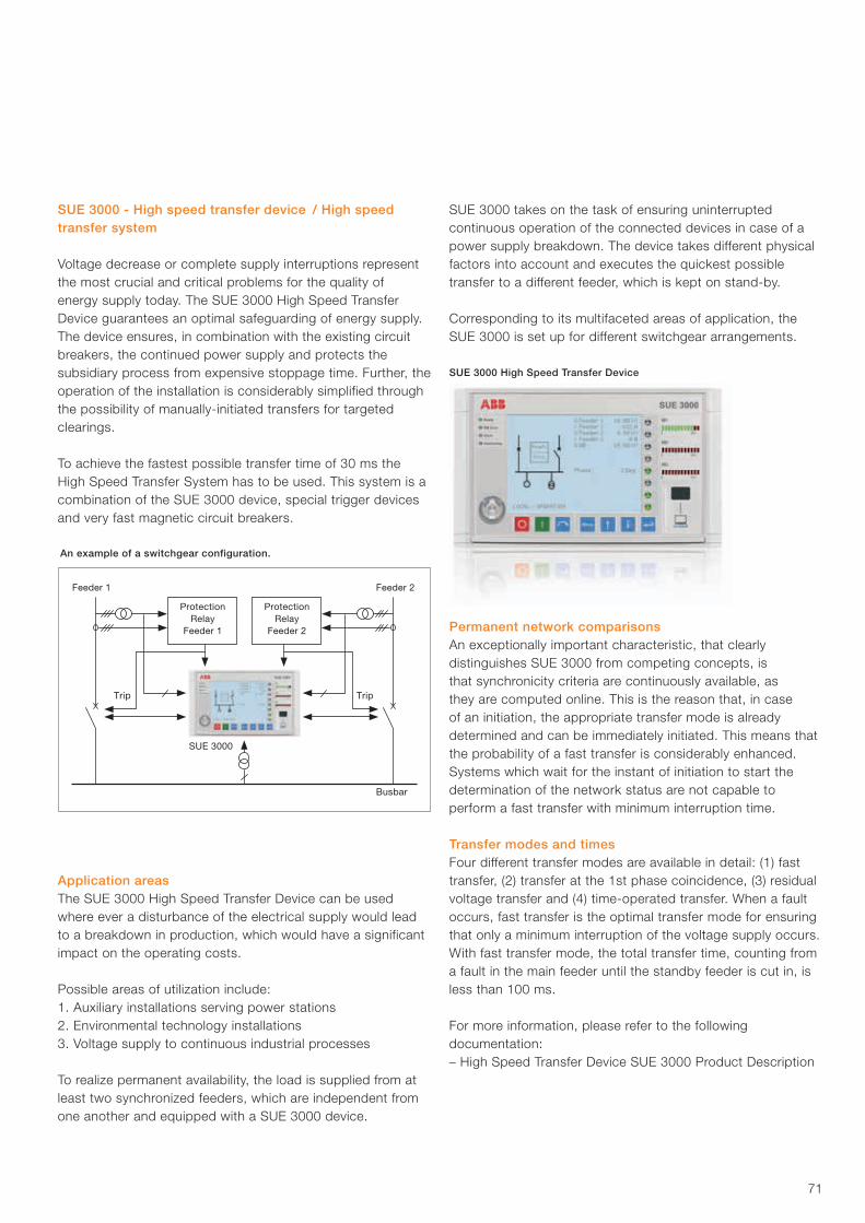
71
SUE 3000 - High speed transfer device / High speed transfer system
Voltage decrease or complete supply interruptions represent the most crucial and critical problems for the quality of energy supply today. The SUE 3000 High Speed Transfer Device guarantees an optimal safeguarding of energy supply. The device ensures, in combination with the existing circuit breakers, the continued power supply and protects the subsidiary process from expensive stoppage time. Further, the operation of the installation is considerably simplified through the possibility of manually-initiated transfers for targeted clearings.
To achieve the fastest possible transfer time of 30 ms theHigh Speed Transfer System has to be used. This system is a combination of the SUE 3000 device, special trigger devices and very fast magnetic circuit breakers.
Application areasThe SUE 3000 High Speed Transfer Device can be used where ever a disturbance of the electrical supply would lead to a breakdown in production, which would have a significant impact on the operating costs.
Possible areas of utilization include:1. Auxiliary installations serving power stations2. Environmental technology installations3. Voltage supply to continuous industrial processes
To realize permanent availability, the load is supplied from at least two synchronized feeders, which are independent from one another and equipped with a SUE 3000 device.
SUE 3000 takes on the task of ensuring uninterrupted continuous operation of the connected devices in case of a power supply breakdown. The device takes different physical factors into account and executes the quickest possible transfer to a different feeder, which is kept on stand-by.
Corresponding to its multifaceted areas of application, theSUE 3000 is set up for different switchgear arrangements.
Permanent network comparisonsAn exceptionally important characteristic, that clearly distinguishes SUE 3000 from competing concepts, is that synchronicity criteria are continuously available, as they are computed online. This is the reason that, in case of an initiation, the appropriate transfer mode is already determined and can be immediately initiated. This means that the probability of a fast transfer is considerably enhanced. Systems which wait for the instant of initiation to start the determination of the network status are not capable to perform a fast transfer with minimum interruption time.
Transfer modes and timesFour different transfer modes are available in detail: (1) fast transfer, (2) transfer at the 1st phase coincidence, (3) residual voltage transfer and (4) time-operated transfer. When a fault occurs, fast transfer is the optimal transfer mode for ensuring that only a minimum interruption of the voltage supply occurs. With fast transfer mode, the total transfer time, counting from a fault in the main feeder until the standby feeder is cut in, is less than 100 ms.
For more information, please refer to the following documentation:– High Speed Transfer Device SUE 3000 Product Description
ProtectionRelay
Feeder 1
ProtectionRelay
Feeder 2
Feeder 1 Feeder 2
SUE 3000
Trip Trip
Busbar
An example of a switchgear configuration.
SUE 3000 High Speed Transfer Device
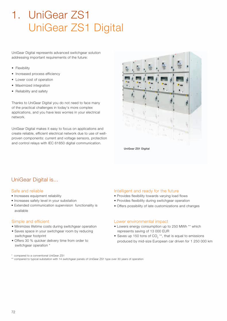
72
1. UniGear ZS1 UniGear ZS1 Digital
UniGear Digital represents advanced switchgear solution addressing important requirements of the future:
• Flexibility
• Increased process efficiency
• Lower cost of operation
• Maximized integration
• Reliability and safety
Thanks to UniGear Digital you do not need to face many of the practical challenges in today‘s more complex applications, and you have less worries in your electrical network.
UniGear Digital makes it easy to focus on applications and create reliable, efficient electrical network due to use of well-proven components: current and voltage sensors, protection and control relays with IEC 61850 digital communication.
Safe and reliable• Increases equipment reliability• Increases safety level in your substation• Extended communication supervision functionality is
available
Intelligent and ready for the future • Provides flexibility towards varying load flows• Provides flexibility during switchgear operation
• Offers possibility of late customizations and changes
* compared to a conventional UniGear ZS1** compared to typical substation with 14 switchgear panels of UniGear ZS1 type over 30 years of operation
Simple and efficient• Minimizes lifetime costs during switchgear operation• Saves space in your switchgear room by reducing
switchgear footprint• Offers 30 % quicker delivery time from order to
switchgear operation *
Lower environmental impact• Lowers energy consumption up to 250 MWh ** which
represents saving of 13 000 EUR• Saves up 150 tons of CO2 **, that is equal to emissions
produced by mid-size European car driven for 1 250 000 km
UniGear Digital is...
UniGear ZS1 Digital
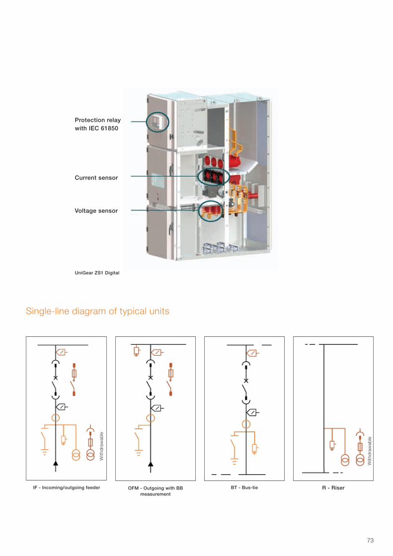
73
Protection relay with IEC 61850
Current sensor
Voltage sensor
With
dra
wab
le
With
dra
wab
le
IF - Incoming/outgoing feeder R - RiserOFM - Outgoing with BB measurement
BT - Bus-tie
Single-line diagram of typical units
UniGear ZS1 Digital
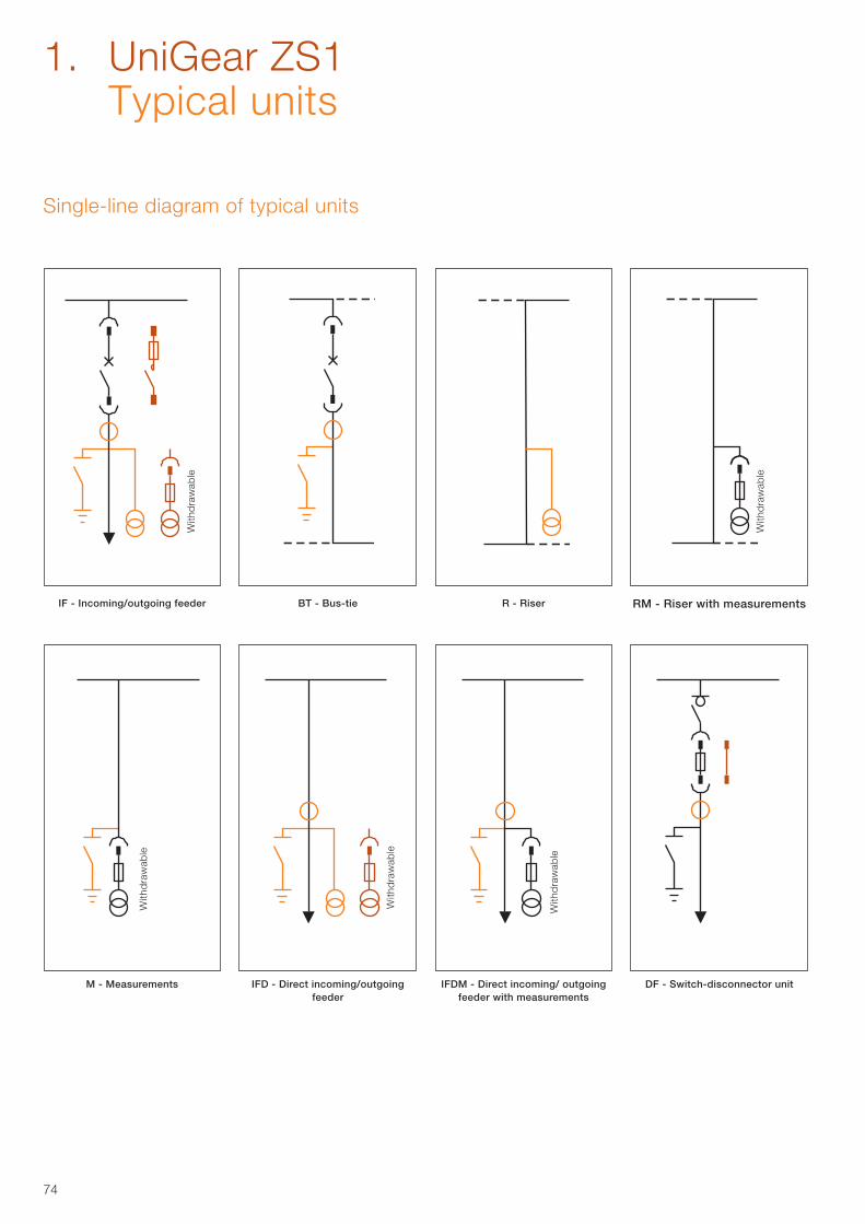
74
With
dra
wab
le
With
dra
wab
le
With
dra
wab
le
With
dra
wab
le
With
dra
wab
le
DF - Switch-disconnector unitM - Measurements IFD - Direct incoming/outgoing feeder
IFDM - Direct incoming/ outgoing feeder with measurements
IF - Incoming/outgoing feeder RM - Riser with measurementsBT - Bus-tie R - Riser
Single-line diagram of typical units
1. UniGear ZS1 Typical units
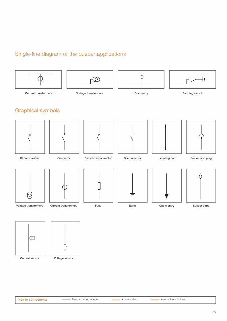
75
Single-line diagram of the busbar applications
Duct entry Current transformers Voltage transformers Earthing switch
Graphical symbols
Switch-disconnectorCircuit-breaker Contactor Socket and plugDisconnector Isolating bar
Fuse Voltage transformers Current transformers Busbar entryEarth Cable entry
Standard components Accessories Alternative solutions Key to components
Current sensor Voltage sensor
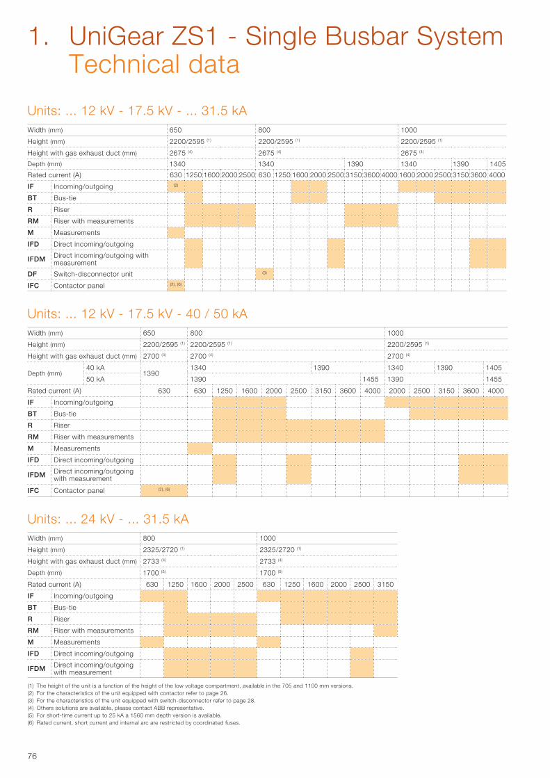
76
Units: ... 12 kV - 17.5 kV - ... 31.5 kAWidth (mm) 650 800 1000
Height (mm) 2200/2595 (1) 2200/2595 (1) 2200/2595 (1)
Height with gas exhaust duct (mm) 2675 (4) 2675 (4) 2675 (4)
Depth (mm) 1340 1340 1390 1340 1390 1405
Rated current (A) 630 1250 1600 2000 2500 630 1250 1600 2000 2500 3150 3600 4000 1600 2000 2500 3150 3600 4000
IF Incoming/outgoing (2)
BT Bus-tie
R Riser
RM Riser with measurements
M Measurements
IFD Direct incoming/outgoing
IFDM Direct incoming/outgoing with measurement
DF Switch-disconnector unit (3)
IFC Contactor panel (2), (6)
Units: ... 12 kV - 17.5 kV - 40 / 50 kAWidth (mm) 650 800 1000
Height (mm) 2200/2595 (1) 2200/2595 (1) 2200/2595 (1)
Height with gas exhaust duct (mm) 2700 (4) 2700 (4) 2700 (4)
Depth (mm) 40 kA
1390 1340 1390 1340 1390 1405
50 kA 1390 1455 1390 1455
Rated current (A) 630 630 1250 1600 2000 2500 3150 3600 4000 2000 2500 3150 3600 4000
IF Incoming/outgoing
BT Bus-tie
R Riser
RM Riser with measurements
M Measurements
IFD Direct incoming/outgoing
IFDM Direct incoming/outgoing with measurement
IFC Contactor panel (2), (6)
Units: ... 24 kV - ... 31.5 kAWidth (mm) 800 1000
Height (mm) 2325/2720 (1) 2325/2720 (1)
Height with gas exhaust duct (mm) 2733 (4) 2733 (4)
Depth (mm) 1700 (5) 1700 (5)
Rated current (A) 630 1250 1600 2000 2500 630 1250 1600 2000 2500 3150
IF Incoming/outgoing
BT Bus-tie
R Riser
RM Riser with measurements
M Measurements
IFD Direct incoming/outgoing
IFDM Direct incoming/outgoing with measurement
(1) The height of the unit is a function of the height of the low voltage compartment, available in the 705 and 1100 mm versions.(2) For the characteristics of the unit equipped with contactor refer to page 26.(3) For the characteristics of the unit equipped with switch-disconnector refer to page 28. (4) Others solutions are available, please contact ABB representative.(5) For short-time current up to 25 kA a 1560 mm depth version is available. (6) Rated current, short current and internal arc are restricted by coordinated fuses.
1. UniGear ZS1 - Single Busbar System Technical data
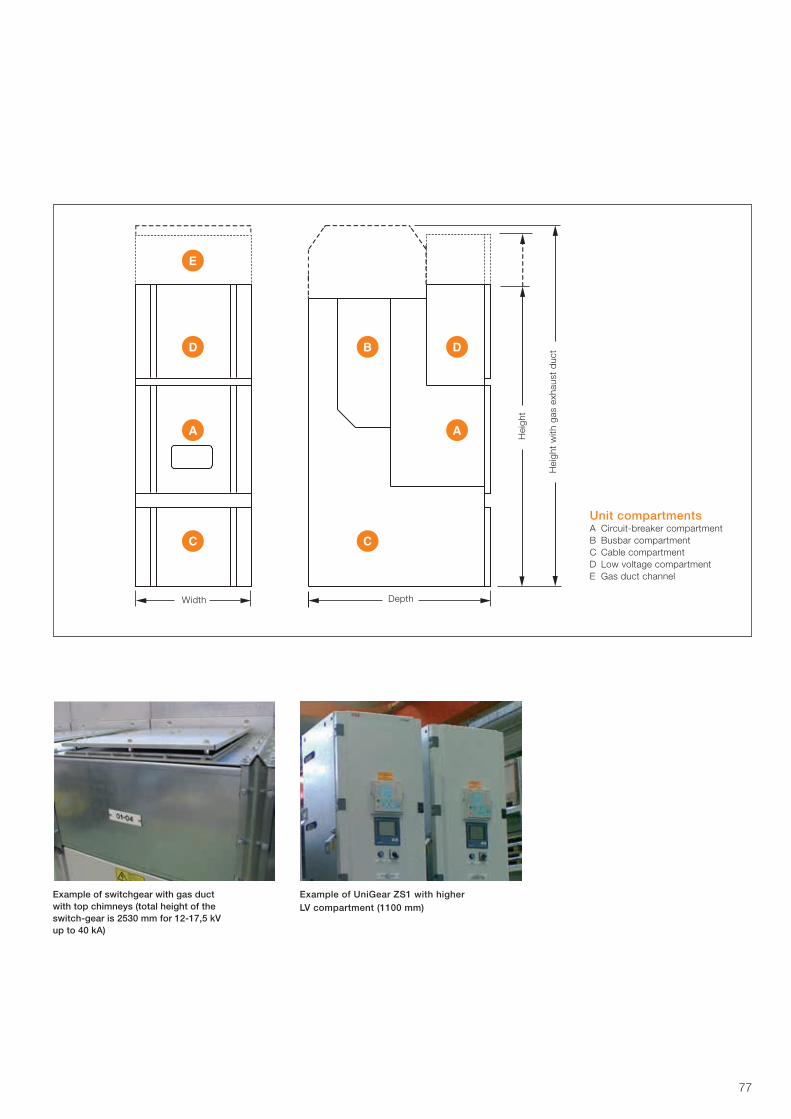
77
Unit compartmentsA Circuit-breaker compartmentB Busbar compartmentC Cable compartmentD Low voltage compartmentE Gas duct channel
Width Depth
Hei
ght
Hei
ght
with
gas
exh
aust
duc
t
Example of switchgear with gas duct with top chimneys (total height of the switch-gear is 2530 mm for 12-17,5 kV up to 40 kA)
Example of UniGear ZS1 with higher LV compartment (1100 mm)
78
79
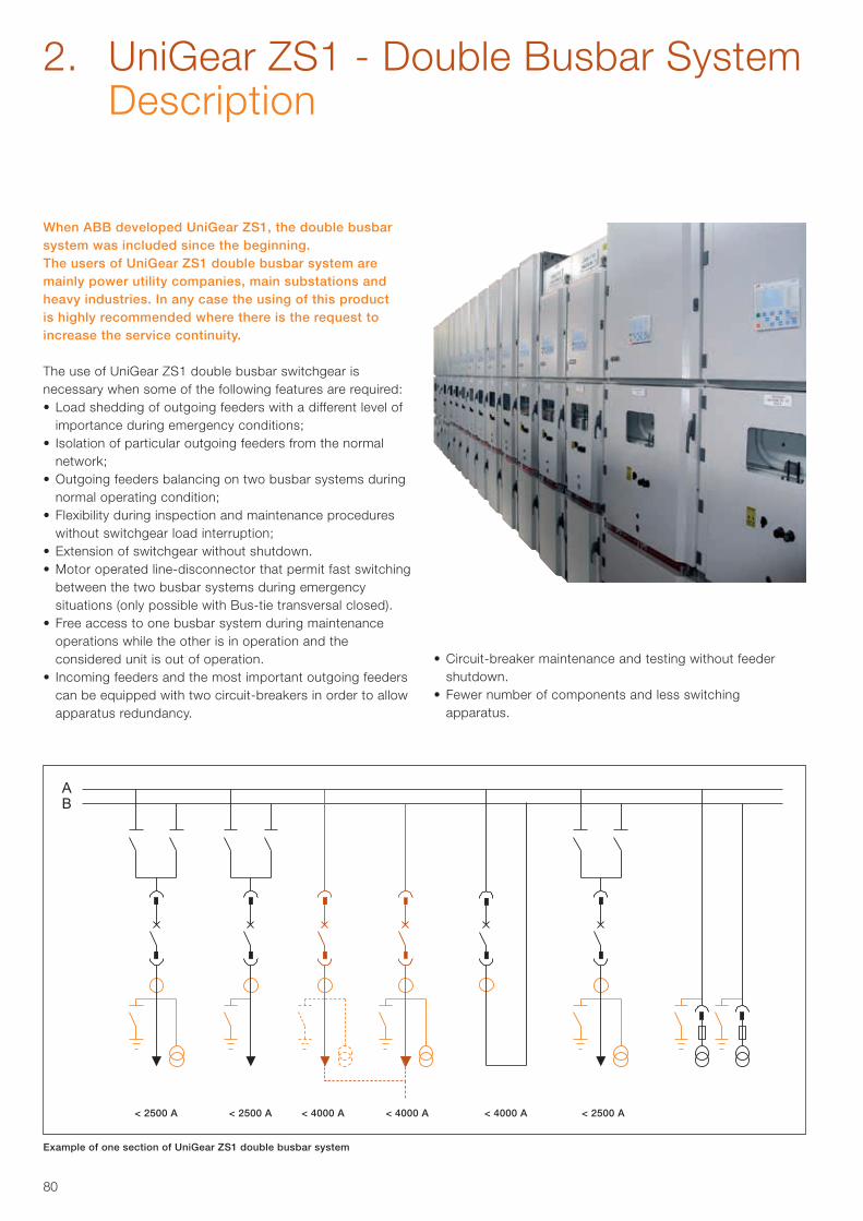
80
< 2500 A < 2500 A < 4000 A < 4000 A < 4000 A < 2500 A
Example of one section of UniGear ZS1 double busbar system
2. UniGear ZS1 - Double Busbar System Description
When ABB developed UniGear ZS1, the double busbar system was included since the beginning.The users of UniGear ZS1 double busbar system are mainly power utility companies, main substations and heavy industries. In any case the using of this product is highly recommended where there is the request to increase the service continuity.
The use of UniGear ZS1 double busbar switchgear is necessary when some of the following features are required:• Load shedding of outgoing feeders with a different level of
importance during emergency conditions;• Isolation of particular outgoing feeders from the normal
network;• Outgoing feeders balancing on two busbar systems during
normal operating condition;• Flexibility during inspection and maintenance procedures
without switchgear load interruption;• Extension of switchgear without shutdown.• Motor operated line-disconnector that permit fast switching
between the two busbar systems during emergency situations (only possible with Bus-tie transversal closed).
• Free access to one busbar system during maintenance operations while the other is in operation and the considered unit is out of operation.
• Incoming feeders and the most important outgoing feeders can be equipped with two circuit-breakers in order to allow apparatus redundancy.
• Circuit-breaker maintenance and testing without feeder shutdown.
• Fewer number of components and less switching apparatus.
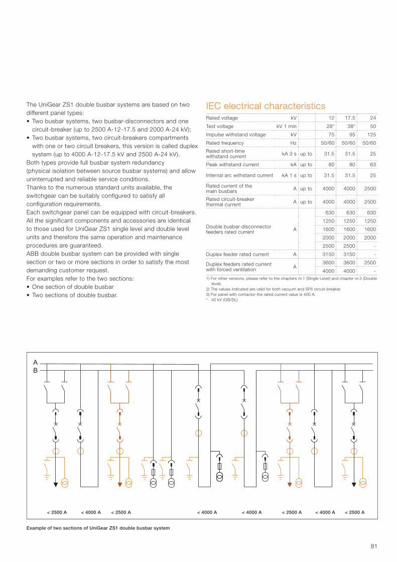
81
< 2500 A < 4000 A < 2500 A < 4000 A < 4000 A < 2500 A < 4000 A < 2500 A
The UniGear ZS1 double busbar systems are based on two different panel types:• Two busbar systems, two busbar-disconnectors and one
circuit-breaker (up to 2500 A-12-17.5 and 2000 A-24 kV);• Two busbar systems, two circuit-breakers compartments
with one or two circuit breakers, this version is called duplex system (up to 4000 A-12-17.5 kV and 2500 A-24 kV).
Both types provide full busbar system redundancy(physical isolation between source busbar systems) and allow uninterrupted and reliable service conditions.Thanks to the numerous standard units available, theswitchgear can be suitably configured to satisfy all configuration requirements.Each switchgear panel can be equipped with circuit-breakers.All the significant components and accessories are identical to those used for UniGear ZS1 single level and double level units and therefore the same operation and maintenance procedures are guaranteed.ABB double busbar system can be provided with single section or two or more sections in order to satisfy the most demanding customer request.For examples refer to the two sections:• One section of double busbar • Two sections of double busbar.
Example of two sections of UniGear ZS1 double busbar system
IEC electrical characteristics Rated voltage kV 12 17.5 24
Test voltage kV 1 min 28* 38* 50
Impulse withstand voltage kV 75 95 125
Rated frequency Hz 50/60 50/60 50/60
Rated short-time withstand current kA 3 s up to 31.5 31.5 25
Peak withstand current kA up to 80 80 63
Internal arc withstand current kA 1 s up to 31.5 31.5 25
Rated current of the main busbars A up to 4000 4000 2500
Rated circuit-breaker thermal current A up to 4000 4000 2500
Double busbar-disconnector feeders rated current A
630 630 630
1250 1250 1250
1600 1600 1600
2000 2000 2000
2500 2500 -
Duplex feeder rated current A 3150 3150 -
Duplex feeders rated currentwith forced ventilation A
3600 3600 2500
4000 4000 -1) For other versions, please refer to the chapters nr.1 (Single Level) and chapter nr.3 (Double
level).2) The values indicated are valid for both vacuum and SF6 circuit-breaker.3) For panel with contactor the rated current value is 400 A. * 42 kV (GB/DL)
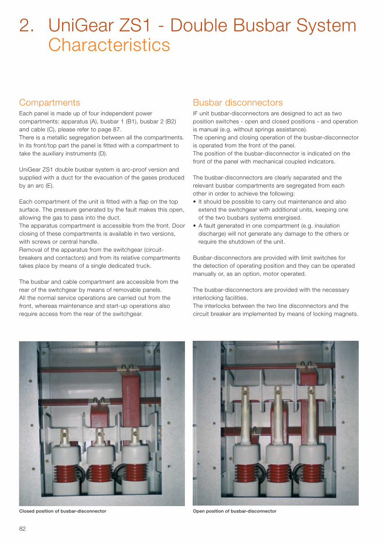
82
CompartmentsEach panel is made up of four independent powercompartments: apparatus (A), busbar 1 (B1), busbar 2 (B2)and cable (C), please refer to page 87.There is a metallic segregation between all the compartments. In its front/top part the panel is fitted with a compartment to take the auxiliary instruments (D).
UniGear ZS1 double busbar system is arc-proof version and supplied with a duct for the evacuation of the gases produced by an arc (E).
Each compartment of the unit is fitted with a flap on the topsurface. The pressure generated by the fault makes this open, allowing the gas to pass into the duct.The apparatus compartment is accessible from the front. Door closing of these compartments is available in two versions, with screws or central handle.Removal of the apparatus from the switchgear (circuit-breakers and contactors) and from its relative compartments takes place by means of a single dedicated truck.
The busbar and cable compartment are accessible from therear of the switchgear by means of removable panels.All the normal service operations are carried out from thefront, whereas maintenance and start-up operations alsorequire access from the rear of the switchgear.
Busbar disconnectorsIF unit busbar-disconnectors are designed to act as two position switches - open and closed positions - and operation is manual (e.g. without springs assistance).The opening and closing operation of the busbar-disconnector is operated from the front of the panel.The position of the busbar-disconnector is indicated on the front of the panel with mechanical coupled indicators.
The busbar-disconnectors are clearly separated and the relevant busbar compartments are segregated from each other in order to achieve the following:• It should be possible to carry out maintenance and also
extend the switchgear with additional units, keeping one of the two busbars systems energised.
• A fault generated in one compartment (e.g. insulation discharge) will not generate any damage to the others or require the shutdown of the unit.
Busbar-disconnectors are provided with limit switches for the detection of operating position and they can be operated manually or, as an option, motor operated.
The busbar-disconnectors are provided with the necessary interlocking facilities.The interlocks between the two line disconnectors and thecircuit breaker are implemented by means of locking magnets.
Closed position of busbar-disconnector Open position of busbar-disconnector
2. UniGear ZS1 - Double Busbar System Characteristics
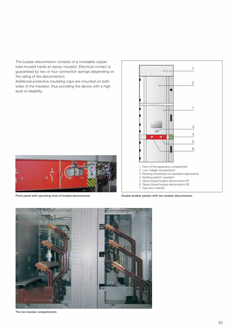
83
7
3
5
6
2
4
1
1 Door of the apparatus compartment2 Low voltage compartment3 Racking-in/racking-out operation (apparatus)4 Earthing switch operation5 Open/closed busbar-disconnector B16 Open/closed busbar-disconnector B27 Gas duct channel
The two busbar compartments
Front panel with operating slots of busbar-disconnector
The busbar-disconnector consists of a moveable copper tube housed inside an epoxy insulator. Electrical contact is guaranteed by two or four connection springs (depending on the rating of the disconnector).Additional protective insulating caps are mounted on both sides of the insulator, thus providing the device with a high level of reliability.
Double busbar system with two busbar-disconnector
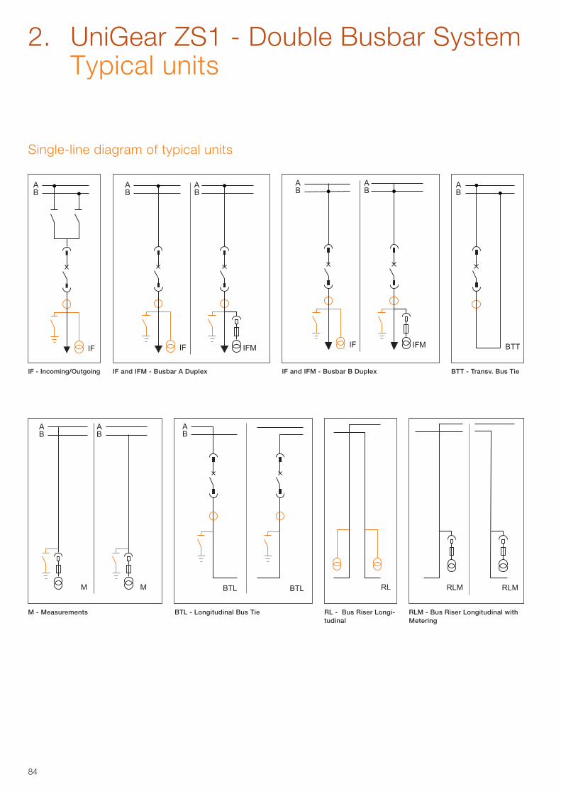
84
IF - Incoming/Outgoing IF and IFM - Busbar A Duplex IF and IFM - Busbar B Duplex BTT - Transv. Bus Tie
2. UniGear ZS1 - Double Busbar System Typical units
Single-line diagram of typical units
M - Measurements BTL - Longitudinal Bus Tie RL - Bus Riser Longi-tudinal
RLM - Bus Riser Longitudinal with Metering
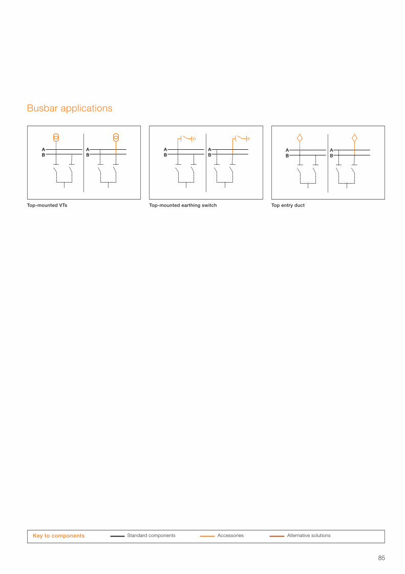
85
Busbar applications
Top-mounted VTs Top-mounted earthing switch Top entry duct
Standard components Accessories Alternative solutions Key to components
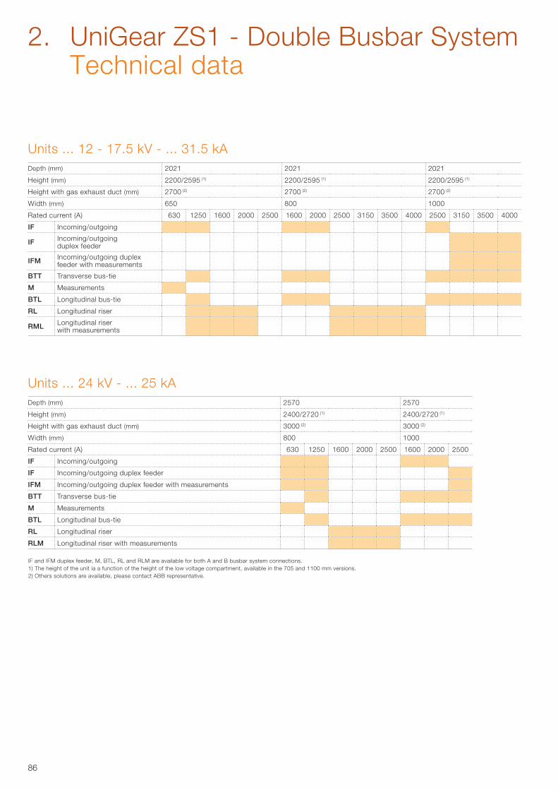
86
IF and IFM duplex feeder, M, BTL, RL and RLM are available for both A and B busbar system connections. 1) The height of the unit ia a function of the height of the low voltage compartment, available in the 705 and 1100 mm versions.2) Others solutions are available, please contact ABB representative.
Units ... 12 - 17.5 kV - ... 31.5 kADepth (mm) 2021 2021 2021
Height (mm) 2200/2595 (1) 2200/2595 (1) 2200/2595 (1)
Height with gas exhaust duct (mm) 2700 (2) 2700 (2) 2700 (2)
Width (mm) 650 800 1000
Rated current (A) 630 1250 1600 2000 2500 1600 2000 2500 3150 3500 4000 2500 3150 3500 4000
IF Incoming/outgoing
IF Incoming/outgoing duplex feeder
IFM Incoming/outgoing duplex feeder with measurements
BTT Transverse bus-tie
M Measurements
BTL Longitudinal bus-tie
RL Longitudinal riser
RML Longitudinal riser with measurements
Units ... 24 kV - ... 25 kADepth (mm) 2570 2570
Height (mm) 2400/2720 (1) 2400/2720 (1)
Height with gas exhaust duct (mm) 3000 (2) 3000 (2)
Width (mm) 800 1000
Rated current (A) 630 1250 1600 2000 2500 1600 2000 2500
IF Incoming/outgoing
IF Incoming/outgoing duplex feeder
IFM Incoming/outgoing duplex feeder with measurements
BTT Transverse bus-tie
M Measurements
BTL Longitudinal bus-tie
RL Longitudinal riser
RLM Longitudinal riser with measurements
2. UniGear ZS1 - Double Busbar System Technical data
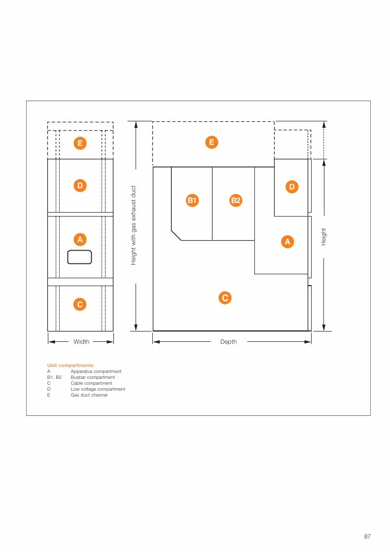
87
Unit compartmentsA Apparatus compartmentB1, B2 Busbar compartmentC Cable compartmentD Low voltage compartmentE Gas duct channel
Hei
ght
Hei
ght
with
gas
exh
aust
duc
t
Width Depth
88
89
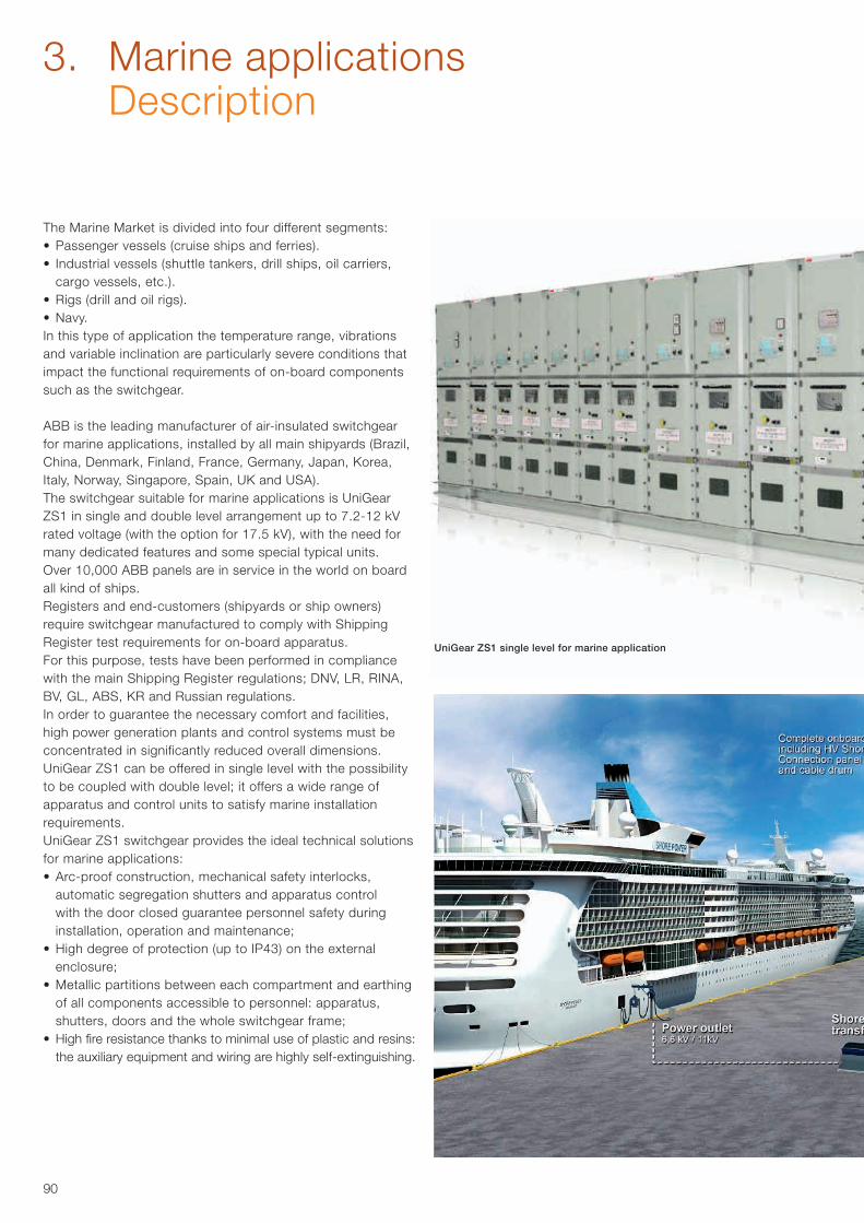
90
3. Marine applications Description
The Marine Market is divided into four different segments:• Passenger vessels (cruise ships and ferries).• Industrial vessels (shuttle tankers, drill ships, oil carriers,
cargo vessels, etc.).• Rigs (drill and oil rigs).• Navy.In this type of application the temperature range, vibrations and variable inclination are particularly severe conditions that impact the functional requirements of on-board components such as the switchgear.
ABB is the leading manufacturer of air-insulated switchgearfor marine applications, installed by all main shipyards (Brazil, China, Denmark, Finland, France, Germany, Japan, Korea, Italy, Norway, Singapore, Spain, UK and USA).The switchgear suitable for marine applications is UniGear ZS1 in single and double level arrangement up to 7.2-12 kV rated voltage (with the option for 17.5 kV), with the need for many dedicated features and some special typical units.Over 10,000 ABB panels are in service in the world on board all kind of ships. Registers and end-customers (shipyards or ship owners) require switchgear manufactured to comply with Shipping Register test requirements for on-board apparatus.For this purpose, tests have been performed in compliance with the main Shipping Register regulations; DNV, LR, RINA, BV, GL, ABS, KR and Russian regulations.In order to guarantee the necessary comfort and facilities, high power generation plants and control systems must be concentrated in significantly reduced overall dimensions.UniGear ZS1 can be offered in single level with the possibility to be coupled with double level; it offers a wide range of apparatus and control units to satisfy marine installation requirements.UniGear ZS1 switchgear provides the ideal technical solutions for marine applications:• Arc-proof construction, mechanical safety interlocks,
automatic segregation shutters and apparatus control with the door closed guarantee personnel safety during installation, operation and maintenance;
• High degree of protection (up to IP43) on the external enclosure;
• Metallic partitions between each compartment and earthing of all components accessible to personnel: apparatus, shutters, doors and the whole switchgear frame;
• High fire resistance thanks to minimal use of plastic and resins: the auxiliary equipment and wiring are highly self-extinguishing.
UniGear ZS1 single level for marine application
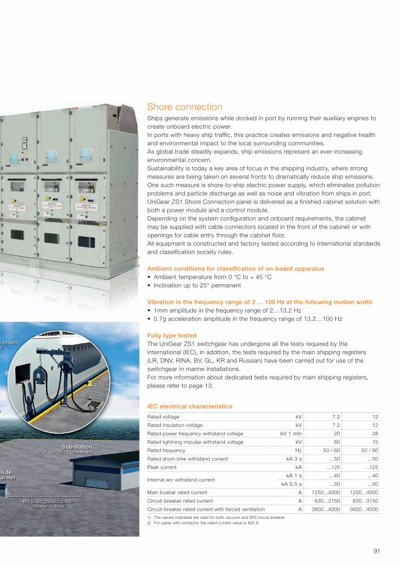
91
IEC electrical characteristics
Rated voltage kV 7.2 12
Rated insulation voltage kV 7.2 12
Rated power frequency withstand voltage kV 1 min 20 28
Rated lightning impulse withstand voltage kV 60 75
Rated frequency Hz 50 / 60 50 / 60
Rated short-time withstand current kA 3 s ...50 ...50
Peak current kA ...125 ...125
Internal arc withstand current kA 1 s ...40 ...40
kA 0.5 s ...50 ...50
Main busbar rated current A 1250...4000 1250...4000
Circuit-breaker rated current A 630...3150 630...3150
Circuit-breaker rated current with forced ventilation A 3600...4000 3600...4000
1) The values indicated are valid for both vacuum and SF6 circuit-breaker.2) For panel with contactor the rated current value is 400 A.
Shore connectionShips generate emissions while docked in port by running their auxiliary engines to create onboard electric power.In ports with heavy ship traffic, this practice creates emissions and negative health and environmental impact to the local surrounding communities.As global trade steadily expands, ship emissions represent an ever-increasing environmental concern. Sustainability is today a key area of focus in the shipping industry, where strong measures are being taken on several fronts to dramatically reduce ship emissions.One such measure is shore-to-ship electric power supply, which eliminates pollution problems and particle discharge as well as noise and vibration from ships in port.UniGear ZS1 Shore Connection panel is delivered as a finished cabinet solution with both a power module and a control module.Depending on the system configuration and onboard requirements, the cabinet may be supplied with cable connectors located in the front of the cabinet or with openings for cable entry through the cabinet floor.All equipment is constructed and factory tested according to international standards and classification society rules.
Ambient conditions for classification of on-board apparatus• Ambient temperature from 0 °C to + 45 °C• Inclination up to 25° permanent
Vibration in the frequency range of 2 … 100 Hz at the following motion width• 1mm amplitude in the frequency range of 2…13.2 Hz• 0.7g acceleration amplitude in the frequency range of 13.2…100 Hz
Fully type testedThe UniGear ZS1 switchgear has undergone all the tests required by the international (IEC), in addition, the tests required by the main shipping registers (LR, DNV, RINA, BV, GL, KR and Russian) have been carried out for use of the switchgear in marine installations.For more information about dedicated tests required by main shipping registers, please refer to page 13.
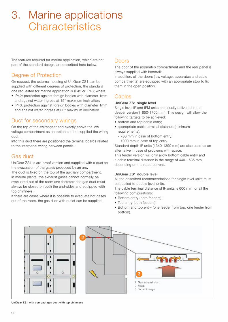
92
1 Gas exhaust duct2 Flaps3 Top chimneys
UniGear ZS1 with compact gas duct with top chimneys
3. Marine applications Characteristics
The features required for marine application, which are not part of the standard design, are described here below.
Degree of ProtectionOn request, the external housing of UniGear ZS1 can be supplied with different degrees of protection, the standard one requested for marine application is IP42 or IP43; where:• IP42: protection against foreign bodies with diameter 1mm
and against water ingress at 15° maximum inclination;• IP43: protection against foreign bodies with diameter 1mm
and against water ingress at 60° maximum inclination.
Duct for secondary wiringsOn the top of the switchgear and exactly above the low voltage compartment as an option can be supplied the wiring duct.Into this duct there are positioned the terminal boards related to the interpanel wiring between panels.
Gas ductUniGear ZS1 is arc-proof version and supplied with a duct for the evacuation of the gases produced by an arc.The duct is fixed on the top of the auxiliary compartment.In marine plants, the exhaust gases cannot normally be evacuated out of the room and therefore the gas duct must always be closed on both the end-sides and equipped with top chimneys.If there are cases where it is possible to evacuate hot gases out of the room, the gas duct with outlet can be supplied.
DoorsThe door of the apparatus compartment and the rear panel is always supplied with handrails.In addition, all the doors (low voltage, apparatus and cablecompartments) are equipped with an appropriate stop to fixthem in the open position.
CablesUniGear ZS1 single levelSingle level IF and IFM units are usually delivered in the deeper version (1650-1700 mm). This design will allow the following targets to be achieved:• bottom and top cable entry;• appropriate cable terminal distance (minimum
requirements): - 700 mm in case of bottom entry; - 1000 mm in case of top entry.Standard depth IF units (1340-1390 mm) are also used as analternative in case of problems with space.This feeder version will only allow bottom cable entry anda cable terminal distance in the range of 440…535 mm,depending on the rated current.
UniGear ZS1 double levelAll the described recommendations for single level units must be applied to double level units.The cable terminal distance of IF units is 600 mm for all thefollowing configurations:• Bottom entry (both feeders);• Top entry (both feeders);• Bottom and top entry (one feeder from top, one feeder from
bottom).
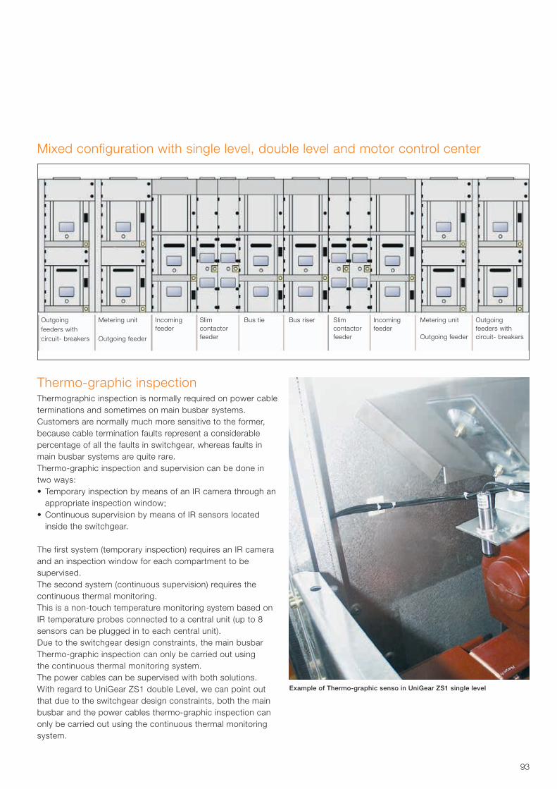
93
Thermo-graphic inspectionThermographic inspection is normally required on power cable terminations and sometimes on main busbar systems.Customers are normally much more sensitive to the former,because cable termination faults represent a considerablepercentage of all the faults in switchgear, whereas faults inmain busbar systems are quite rare.Thermo-graphic inspection and supervision can be done intwo ways:• Temporary inspection by means of an IR camera through an
appropriate inspection window;• Continuous supervision by means of IR sensors located
inside the switchgear.
The first system (temporary inspection) requires an IR camera and an inspection window for each compartment to be supervised.The second system (continuous supervision) requires thecontinuous thermal monitoring.This is a non-touch temperature monitoring system based on IR temperature probes connected to a central unit (up to 8 sensors can be plugged in to each central unit).Due to the switchgear design constraints, the main busbarThermo-graphic inspection can only be carried out usingthe continuous thermal monitoring system.The power cables can be supervised with both solutions.With regard to UniGear ZS1 double Level, we can point out that due to the switchgear design constraints, both the mainbusbar and the power cables thermo-graphic inspection canonly be carried out using the continuous thermal monitoring system.
Mixed configuration with single level, double level and motor control center
Outgoing feeders with circuit- breakers
Metering unit
Outgoing feeder
Incoming feeder
Slim contactor feeder
Slim contactor feeder
Incoming feeder
Bus tie Bus riser Metering unit
Outgoing feeder
Outgoing feeders with circuit- breakers
Example of Thermo-graphic senso in UniGear ZS1 single level
94
For the typical units used in marine application please refer to page 95 for UniGear ZS1 single level and page 102/103 for UniGear ZS1 double level.The required units, which are not part of the standard design, are described here below.
Earthing transformer unitsFrom the electrical point of view, marine plants are based on isolated networks (isolated neutral point).The main consequences are as follows:• the network can be operated with single-phase earth fault;• earth fault detection is very difficult, due to the very low
earth fault current.
In order to increase this and therefore allow releases to operate on single-phase earth faults, two solutions can be used:• connecting the secondary winding of the generator to
ground by means of a resistor;• installing an earthing transformer in the network.
For this reason, the UniGear ZS1 range must be enhanced with two addition typical units:• ME: Busbar metering unit with earthing transformer feeder;• RE: Rise with earthing transformer feeder.In the case of switchgear with a single busbar section, ME can be used for this purpose; in the case of switchgear equipped with two busbar sections, both ME and RE units must be used, in order to cover all the schemes.
Additional features of Measurement and Riser unitsOut of choice, M and R units should be equipped with fixed Voltage Transformers instead of withdrawable VT’s with fuses.In this configuration the “apparatus compartment”, where is placed the VT’s truck, will be used as an additional auxiliary compartment. It is fully segregated from the power compartments with metallic partitions and designed as a low voltage compartment with respect to the safety rules.The inside rear and side walls of the compartment is fitted with the grid plate for fixing the auxiliary equipment.This will be equipped with the relevant left-hand side duct for wiring entry from the bottom and exit to the top-mounted Low voltage compartment.
3. Marine Applications Typical units
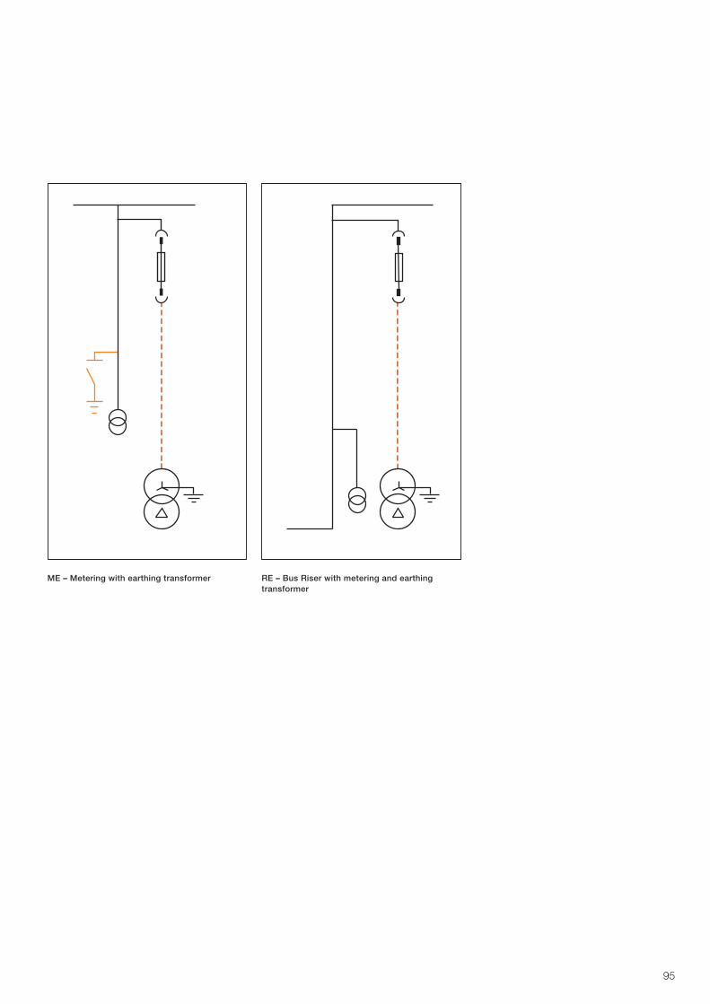
95
ME – Metering with earthing transformer RE – Bus Riser with metering and earthing transformer
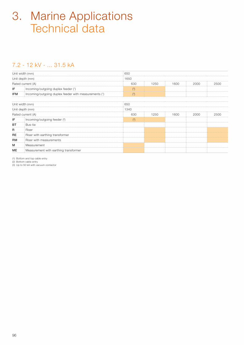
96
7.2 - 12 kV - ... 31.5 kAUnit width (mm) 650
Unit depth (mm) 1650
Rated current (A) 630 1250 1600 2000 2500
IF Incoming/outgoing duplex feeder (1) (3)
IFM Incoming/outgoing duplex feeder with measurements (1) (3)
Unit width (mm) 650
Unit depth (mm) 1340
Rated current (A) 630 1250 1600 2000 2500
IF Incoming/outgoing feeder (2) (3)
BT Bus-tie
R Riser
RE Riser with earthing transformer
RM Riser with measurements
M Measurement
ME Measurement with earthing transformer
(1) Bottom and top cable entry(2) Bottom cable entry(3) Up to 50 kA with vacuum contactor
3. Marine Applications Technical data
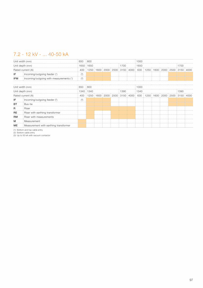
97
(1) Bottom and top cable entry(2) Bottom cable entry(3) Up to 50 kA with vacuum contactor
7.2 - 12 kV - ... 40-50 kAUnit width (mm) 650 800 1000
Unit depth (mm) 1650 1650 1700 1650 1700
Rated current (A) 400 1250 1600 2000 2500 3150 4000 630 1250 1600 2000 2500 3150 4000
IF Incoming/outgoing feeder (1) (3)
IFM Incoming/outgoing with measurements (1) (3)
Unit width (mm) 650 800 1000
Unit depth (mm) 1340 1340 1390 1340 1390
Rated current (A) 400 1250 1600 2000 2500 3150 4000 630 1250 1600 2000 2500 3150 4000
IF Incoming/outgoing feeder (2) (3)
BT Bus-tie
R Riser
RE Riser with earthing transformer
RM Riser with measurements
M Measurement
ME Measurement with earthing transformer
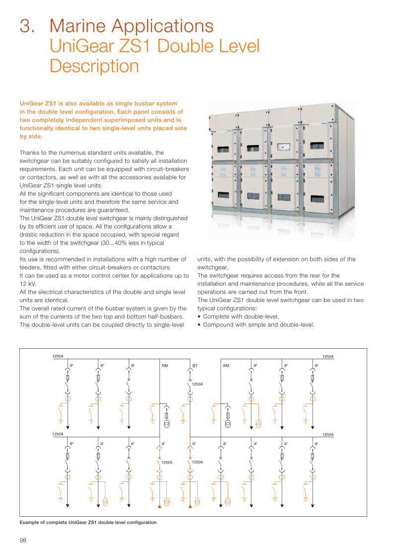
98
3. Marine Applications UniGear ZS1 Double Level Description
Example of complete UniGear ZS1 double level configuration
UniGear ZS1 is also available as single busbar system in the double level configuration. Each panel consists of two completely independent superimposed units and is functionally identical to two single-level units placed side by side.
Thanks to the numerous standard units available, the switchgear can be suitably configured to satisfy all installation requirements. Each unit can be equipped with circuit-breakers or contactors, as well as with all the accessories available for UniGear ZS1 single level units.All the significant components are identical to those used for the single-level units and therefore the same service and maintenance procedures are guaranteed.The UniGear ZS1 double level switchgear is mainly distinguished by its efficient use of space. All the configurations allow a drastic reduction in the space occupied, with special regard to the width of the switchgear (30...40% less in typical configurations).Its use is recommended in installations with a high number of feeders, fitted with either circuit-breakers or contactors.It can be used as a motor control center for applications up to 12 kV.All the electrical characteristics of the double and single level units are identical.The overall rated current of the busbar system is given by the sum of the currents of the two top and bottom half-busbars. The double-level units can be coupled directly to single-level
units, with the possibility of extension on both sides of the switchgear.The switchgear requires access from the rear for theinstallation and maintenance procedures, while all the service operations are carried out from the front.The UniGear ZS1 double level switchgear can be used in two typical configurations:• Complete with double-level.• Compound with simple and double-level.
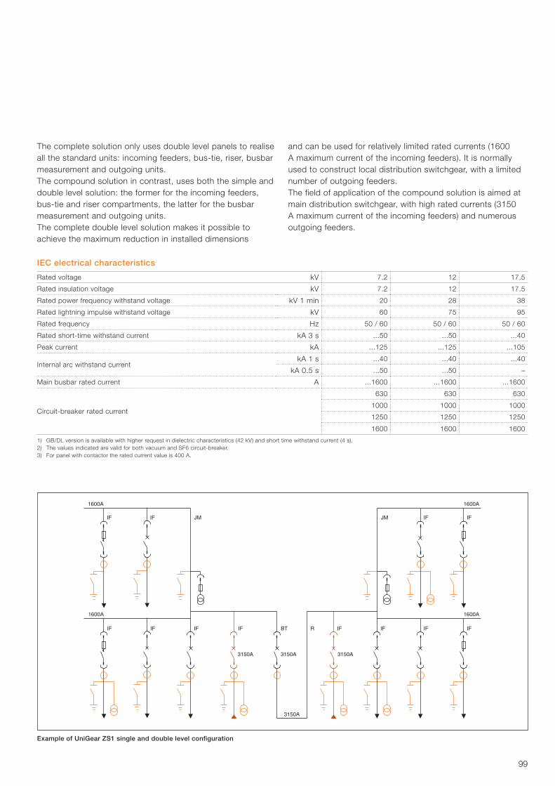
99
Example of UniGear ZS1 single and double level configuration
The complete solution only uses double level panels to realise all the standard units: incoming feeders, bus-tie, riser, busbar measurement and outgoing units.The compound solution in contrast, uses both the simple and double level solution: the former for the incoming feeders, bus-tie and riser compartments, the latter for the busbar measurement and outgoing units.The complete double level solution makes it possible to achieve the maximum reduction in installed dimensions
and can be used for relatively limited rated currents (1600 A maximum current of the incoming feeders). It is normally used to construct local distribution switchgear, with a limited number of outgoing feeders.The field of application of the compound solution is aimed at main distribution switchgear, with high rated currents (3150 A maximum current of the incoming feeders) and numerous outgoing feeders.
IEC electrical characteristics
Rated voltage kV 7.2 12 17.5
Rated insulation voltage kV 7.2 12 17.5
Rated power frequency withstand voltage kV 1 min 20 28 38
Rated lightning impulse withstand voltage kV 60 75 95
Rated frequency Hz 50 / 60 50 / 60 50 / 60
Rated short-time withstand current kA 3 s ...50 ...50 ...40
Peak current kA ...125 ...125 ...105
Internal arc withstand current kA 1 s ...40 ...40 ...40
kA 0.5 s ...50 ...50 –
Main busbar rated current A ...1600 ...1600 ...1600
Circuit-breaker rated current
630 630 630
1000 1000 1000
1250 1250 1250
1600 1600 1600
1) GB/DL version is available with higher request in dielectric characteristics (42 kV) and short time withstand current (4 s).2) The values indicated are valid for both vacuum and SF6 circuit-breaker.3) For panel with contactor the rated current value is 400 A.
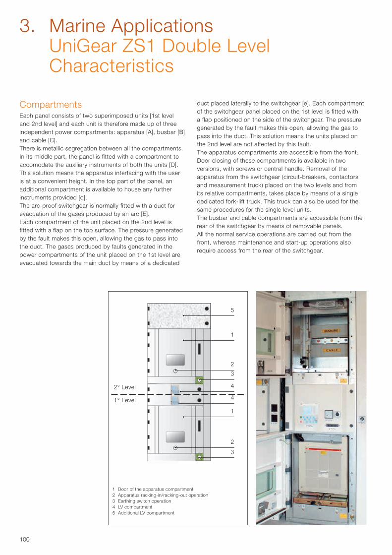
100
5
2
3
4
4
1
2
3
1
2° Level
1° Level
1 Door of the apparatus compartment2 Apparatus racking-in/racking-out operation3 Earthing switch operation4 LV compartment5 Additional LV compartment
CompartmentsEach panel consists of two superimposed units [1st level and 2nd level] and each unit is therefore made up of three independent power compartments: apparatus [A], busbar [B] and cable [C].There is metallic segregation between all the compartments.In its middle part, the panel is fitted with a compartment to accomodate the auxiliary instruments of both the units [D].This solution means the apparatus interfacing with the user is at a convenient height. In the top part of the panel, an additional compartment is available to house any further instruments provided [d].The arc-proof switchgear is normally fitted with a duct for evacuation of the gases produced by an arc [E].Each compartment of the unit placed on the 2nd level is fitted with a flap on the top surface. The pressure generated by the fault makes this open, allowing the gas to pass into the duct. The gases produced by faults generated in the power compartments of the unit placed on the 1st level are evacuated towards the main duct by means of a dedicated
duct placed laterally to the switchgear [e]. Each compartment of the switchgear panel placed on the 1st level is fitted with a flap positioned on the side of the switchgear. The pressure generated by the fault makes this open, allowing the gas to pass into the duct. This solution means the units placed on the 2nd level are not affected by this fault.The apparatus compartments are accessible from the front.Door closing of these compartments is available in two versions, with screws or central handle. Removal of the apparatus from the switchgear (circuit-breakers, contactors and measurement truck) placed on the two levels and from its relative compartments, takes place by means of a single dedicated fork-lift truck. This truck can also be used for the same procedures for the single level units.The busbar and cable compartments are accessible from the rear of the switchgear by means of removable panels.All the normal service operations are carried out from the front, whereas maintenance and start-up operations also require access from the rear of the switchgear.
3. Marine Applications UniGear ZS1 Double Level Characteristics
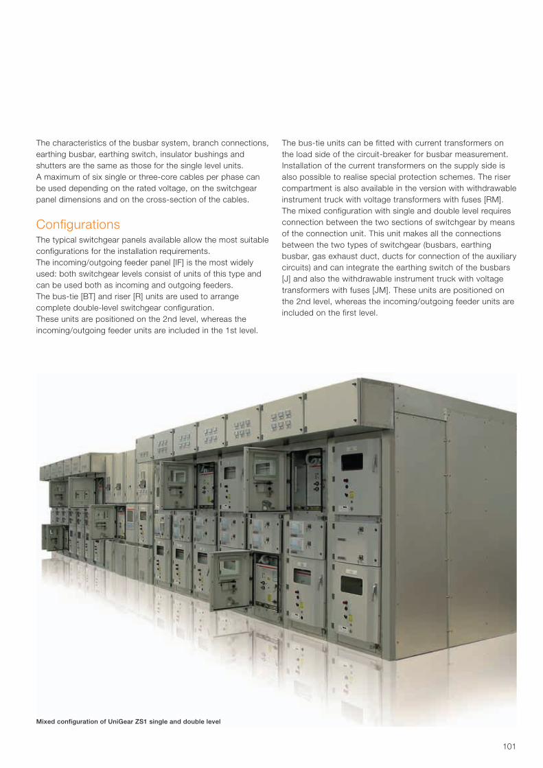
101
Mixed configuration of UniGear ZS1 single and double level
The characteristics of the busbar system, branch connections, earthing busbar, earthing switch, insulator bushings and shutters are the same as those for the single level units.A maximum of six single or three-core cables per phase can be used depending on the rated voltage, on the switchgear panel dimensions and on the cross-section of the cables.
ConfigurationsThe typical switchgear panels available allow the most suitable configurations for the installation requirements.The incoming/outgoing feeder panel [IF] is the most widely used: both switchgear levels consist of units of this type and can be used both as incoming and outgoing feeders.The bus-tie [BT] and riser [R] units are used to arrange complete double-level switchgear configuration.These units are positioned on the 2nd level, whereas the incoming/outgoing feeder units are included in the 1st level.
The bus-tie units can be fitted with current transformers on the load side of the circuit-breaker for busbar measurement.Installation of the current transformers on the supply side is also possible to realise special protection schemes. The riser compartment is also available in the version with withdrawable instrument truck with voltage transformers with fuses [RM].The mixed configuration with single and double level requires connection between the two sections of switchgear by means of the connection unit. This unit makes all the connections between the two types of switchgear (busbars, earthing busbar, gas exhaust duct, ducts for connection of the auxiliary circuits) and can integrate the earthing switch of the busbars [J] and also the withdrawable instrument truck with voltage transformers with fuses [JM]. These units are positioned on the 2nd level, whereas the incoming/outgoing feeder units are included on the first level.
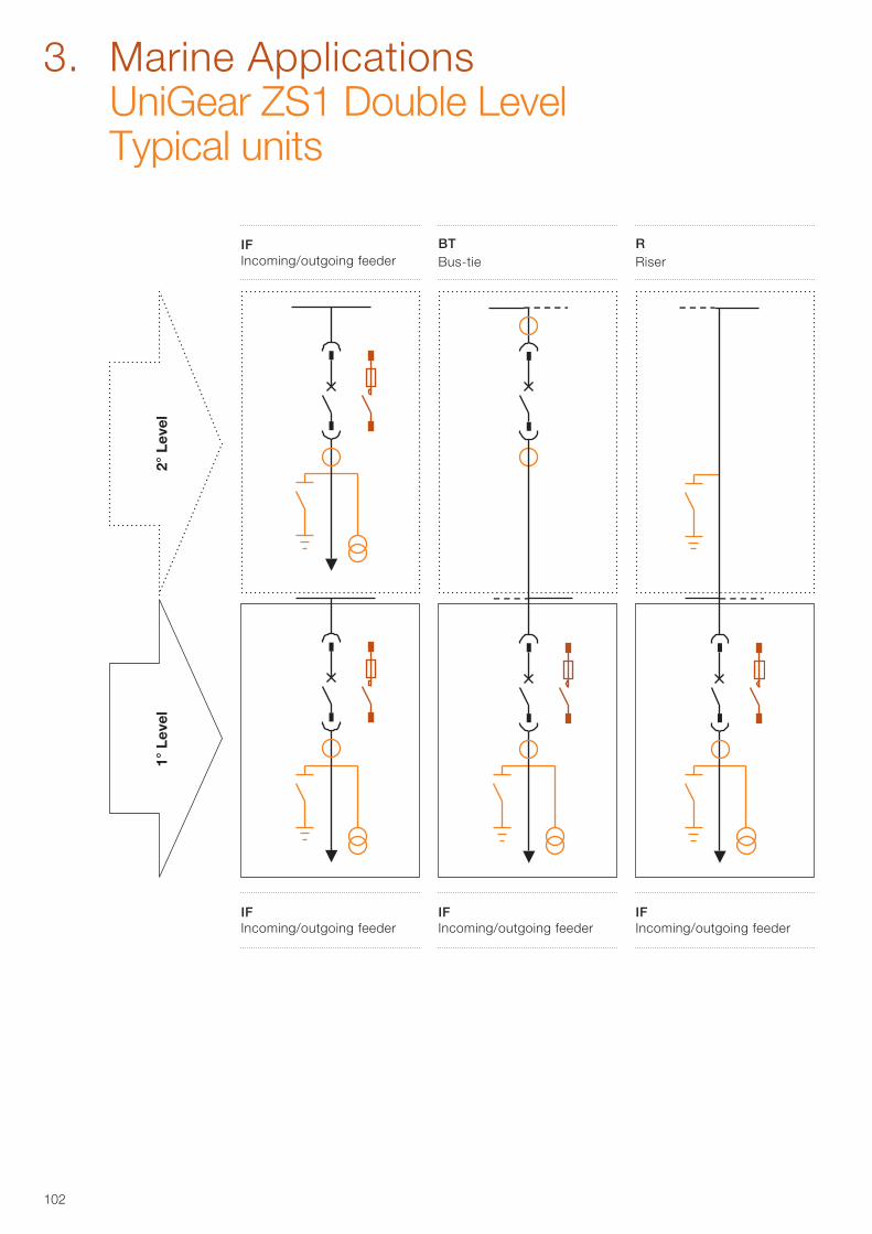
102
2° L
evel
1° L
evel
IF Incoming/outgoing feeder
3. Marine Applications UniGear ZS1 Double Level Typical units
R Riser
BT Bus-tie
IF Incoming/outgoing feeder
IF Incoming/outgoing feeder
IF Incoming/outgoing feeder
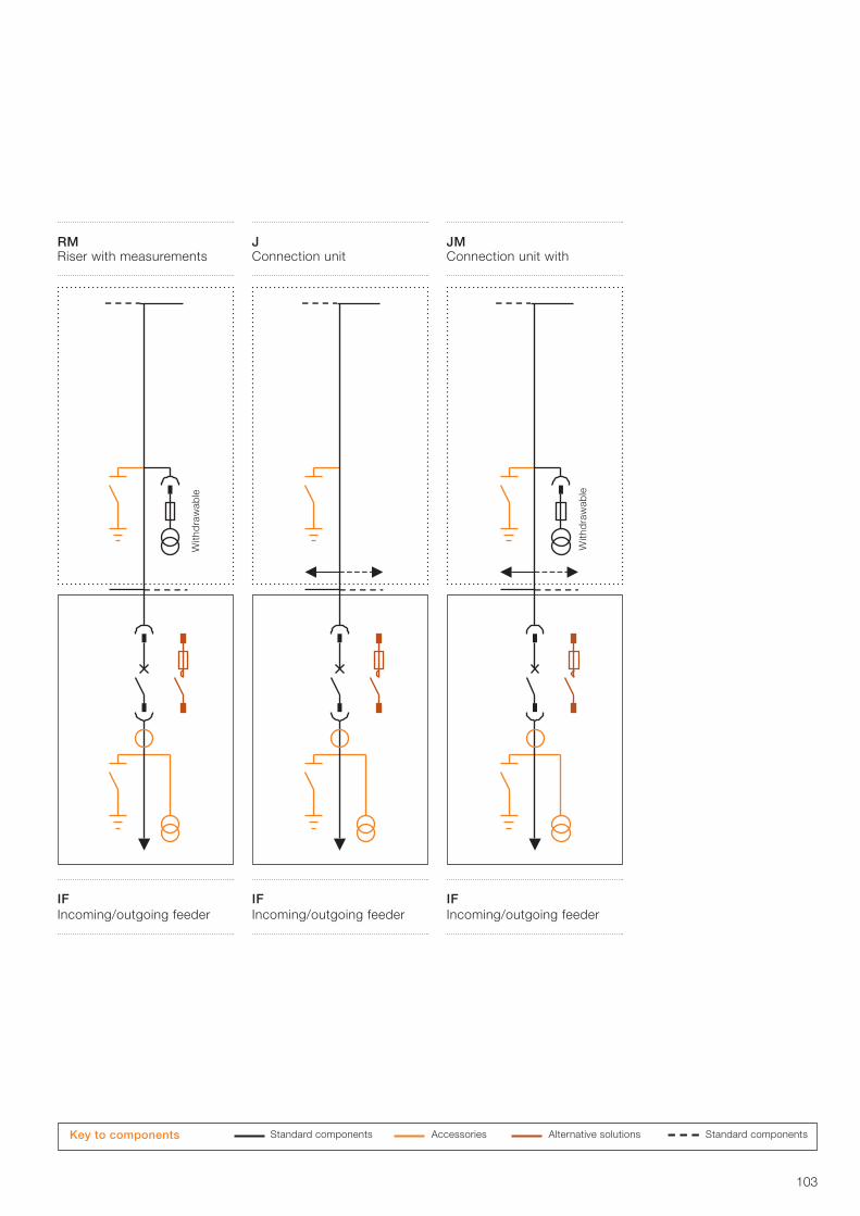
103
IF Incoming/outgoing feeder
With
dra
wab
le
JM Connection unit with
Standard components Accessories Alternative solutions Standard components Key to components
J Connection unit
RM Riser with measurements
IF Incoming/outgoing feeder
IF Incoming/outgoing feeder
With
dra
wab
le
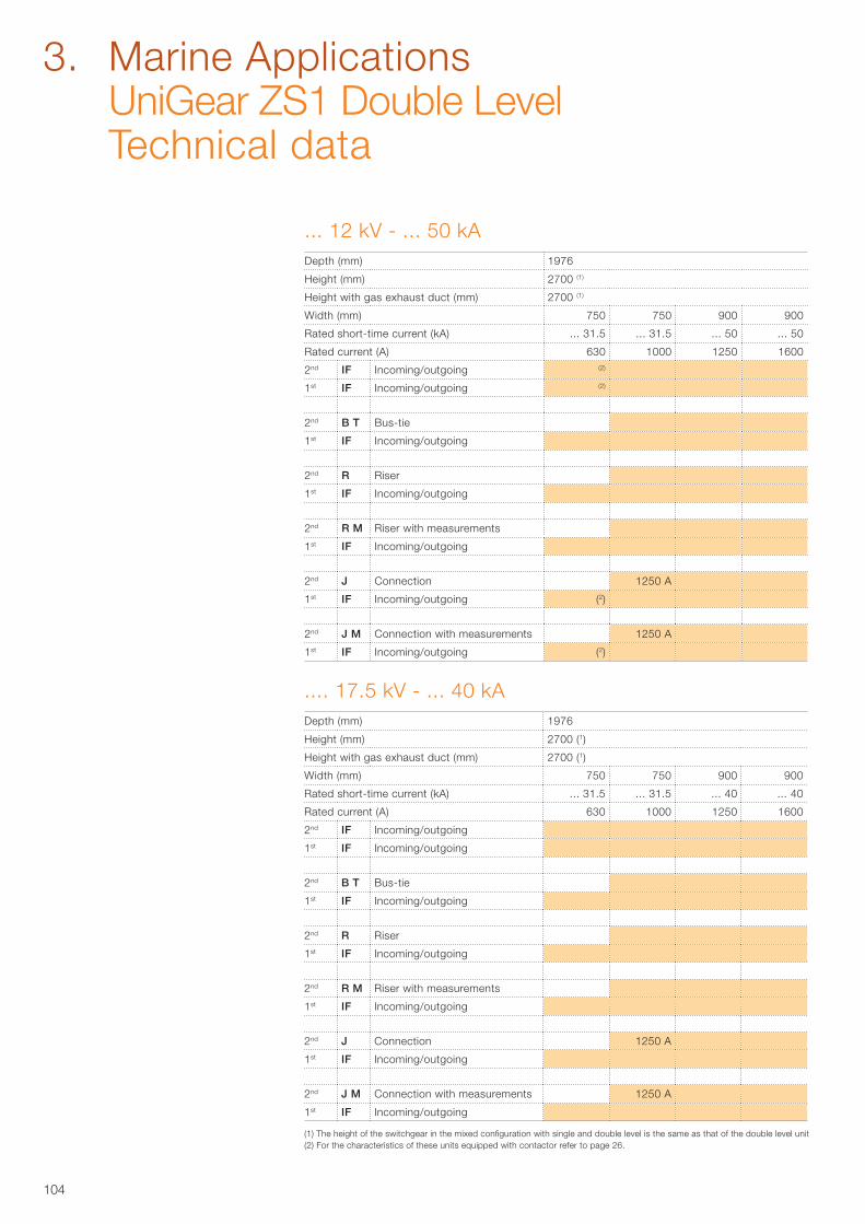
104
... 12 kV - ... 50 kADepth (mm) 1976
Height (mm) 2700 (1)
Height with gas exhaust duct (mm) 2700 (1)
Width (mm) 750 750 900 900
Rated short-time current (kA) ... 31.5 ... 31.5 ... 50 ... 50
Rated current (A) 630 1000 1250 1600
2nd IF Incoming/outgoing (2)
1st IF Incoming/outgoing (2)
2nd B T Bus-tie
1st IF Incoming/outgoing
2nd R Riser
1st IF Incoming/outgoing
2nd R M Riser with measurements
1st IF Incoming/outgoing
2nd J Connection 1250 A
1st IF Incoming/outgoing (2)
2nd J M Connection with measurements 1250 A
1st IF Incoming/outgoing (2)
(1) The height of the switchgear in the mixed configuration with single and double level is the same as that of the double level unit(2) For the characteristics of these units equipped with contactor refer to page 26.
.... 17.5 kV - ... 40 kADepth (mm) 1976
Height (mm) 2700 (1)
Height with gas exhaust duct (mm) 2700 (1)
Width (mm) 750 750 900 900
Rated short-time current (kA) ... 31.5 ... 31.5 ... 40 ... 40
Rated current (A) 630 1000 1250 1600
2nd IF Incoming/outgoing
1st IF Incoming/outgoing
2nd B T Bus-tie
1st IF Incoming/outgoing
2nd R Riser
1st IF Incoming/outgoing
2nd R M Riser with measurements
1st IF Incoming/outgoing
2nd J Connection 1250 A
1st IF Incoming/outgoing
2nd J M Connection with measurements 1250 A
1st IF Incoming/outgoing
3. Marine Applications UniGear ZS1 Double Level Technical data
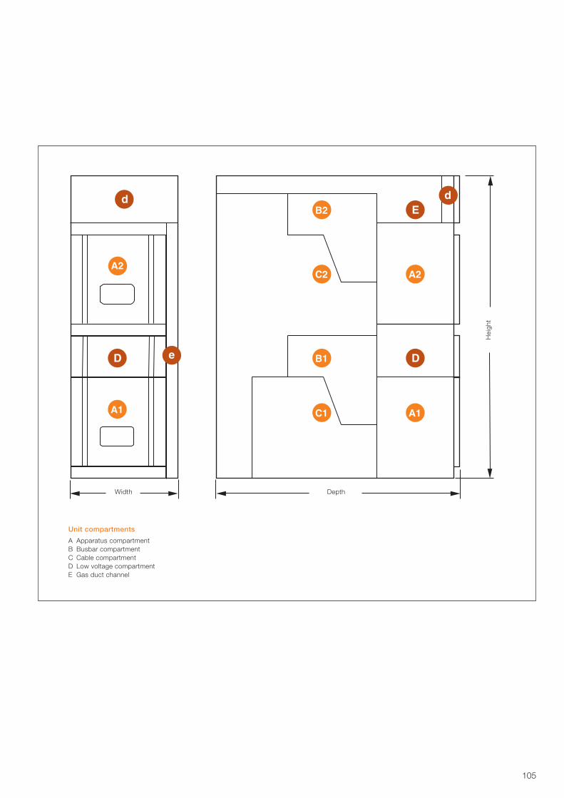
105
Unit compartments
A Apparatus compartmentB Busbar compartmentC Cable compartmentD Low voltage compartmentE Gas duct channel
Width DepthH
eigh
t

106
Notes

Contact us
More product information: www.abb.com/productguide
The data and illustrations are not binding. We reserve the right to make changes without notice in the course of technical development of the product.
© Copyright 2017 ABB.All rights reserved.
1VC
P00
0138
- R
ev.
H,
en -
Tec
hnic
al c
atal
ogue
- 2
017.
09 -
(Uni
Gea
r Z
S1)
(gs)
Your sales contact: www.abb.com/contacts